WO2011122360A1 - 画像読取装置、画像検査装置および印刷装置、並びに、カメラ位置調整方法 - Google Patents
画像読取装置、画像検査装置および印刷装置、並びに、カメラ位置調整方法 Download PDFInfo
- Publication number
- WO2011122360A1 WO2011122360A1 PCT/JP2011/056453 JP2011056453W WO2011122360A1 WO 2011122360 A1 WO2011122360 A1 WO 2011122360A1 JP 2011056453 W JP2011056453 W JP 2011056453W WO 2011122360 A1 WO2011122360 A1 WO 2011122360A1
- Authority
- WO
- WIPO (PCT)
- Prior art keywords
- image
- printing
- imaging
- unit
- cameras
- Prior art date
- Legal status (The legal status is an assumption and is not a legal conclusion. Google has not performed a legal analysis and makes no representation as to the accuracy of the status listed.)
- Ceased
Links
Images




Classifications
-
- H—ELECTRICITY
- H04—ELECTRIC COMMUNICATION TECHNIQUE
- H04N—PICTORIAL COMMUNICATION, e.g. TELEVISION
- H04N1/00—Scanning, transmission or reproduction of documents or the like, e.g. facsimile transmission; Details thereof
- H04N1/00127—Connection or combination of a still picture apparatus with another apparatus, e.g. for storage, processing or transmission of still picture signals or of information associated with a still picture
- H04N1/00326—Connection or combination of a still picture apparatus with another apparatus, e.g. for storage, processing or transmission of still picture signals or of information associated with a still picture with a data reading, recognizing or recording apparatus, e.g. with a bar-code apparatus
-
- G—PHYSICS
- G01—MEASURING; TESTING
- G01N—INVESTIGATING OR ANALYSING MATERIALS BY DETERMINING THEIR CHEMICAL OR PHYSICAL PROPERTIES
- G01N21/00—Investigating or analysing materials by the use of optical means, i.e. using sub-millimetre waves, infrared, visible or ultraviolet light
- G01N21/84—Systems specially adapted for particular applications
- G01N21/88—Investigating the presence of flaws or contamination
- G01N21/89—Investigating the presence of flaws or contamination in moving material, e.g. running paper or textiles
- G01N21/8901—Optical details; Scanning details
- G01N21/8903—Optical details; Scanning details using a multiple detector array
-
- H—ELECTRICITY
- H04—ELECTRIC COMMUNICATION TECHNIQUE
- H04N—PICTORIAL COMMUNICATION, e.g. TELEVISION
- H04N1/00—Scanning, transmission or reproduction of documents or the like, e.g. facsimile transmission; Details thereof
- H04N1/00127—Connection or combination of a still picture apparatus with another apparatus, e.g. for storage, processing or transmission of still picture signals or of information associated with a still picture
- H04N1/00326—Connection or combination of a still picture apparatus with another apparatus, e.g. for storage, processing or transmission of still picture signals or of information associated with a still picture with a data reading, recognizing or recording apparatus, e.g. with a bar-code apparatus
- H04N1/00328—Connection or combination of a still picture apparatus with another apparatus, e.g. for storage, processing or transmission of still picture signals or of information associated with a still picture with a data reading, recognizing or recording apparatus, e.g. with a bar-code apparatus with an apparatus processing optically-read information
- H04N1/00334—Connection or combination of a still picture apparatus with another apparatus, e.g. for storage, processing or transmission of still picture signals or of information associated with a still picture with a data reading, recognizing or recording apparatus, e.g. with a bar-code apparatus with an apparatus processing optically-read information with an apparatus processing barcodes or the like
-
- H—ELECTRICITY
- H04—ELECTRIC COMMUNICATION TECHNIQUE
- H04N—PICTORIAL COMMUNICATION, e.g. TELEVISION
- H04N1/00—Scanning, transmission or reproduction of documents or the like, e.g. facsimile transmission; Details thereof
- H04N1/04—Scanning arrangements, i.e. arrangements for the displacement of active reading or reproducing elements relative to the original or reproducing medium, or vice versa
- H04N1/19—Scanning arrangements, i.e. arrangements for the displacement of active reading or reproducing elements relative to the original or reproducing medium, or vice versa using multi-element arrays
- H04N1/191—Scanning arrangements, i.e. arrangements for the displacement of active reading or reproducing elements relative to the original or reproducing medium, or vice versa using multi-element arrays the array comprising a one-dimensional [1D] array
- H04N1/192—Simultaneously or substantially simultaneously scanning picture elements on one main scanning line
- H04N1/193—Simultaneously or substantially simultaneously scanning picture elements on one main scanning line using electrically scanned linear arrays, e.g. linear CCD arrays
-
- H—ELECTRICITY
- H04—ELECTRIC COMMUNICATION TECHNIQUE
- H04N—PICTORIAL COMMUNICATION, e.g. TELEVISION
- H04N1/00—Scanning, transmission or reproduction of documents or the like, e.g. facsimile transmission; Details thereof
- H04N1/04—Scanning arrangements, i.e. arrangements for the displacement of active reading or reproducing elements relative to the original or reproducing medium, or vice versa
- H04N1/19—Scanning arrangements, i.e. arrangements for the displacement of active reading or reproducing elements relative to the original or reproducing medium, or vice versa using multi-element arrays
- H04N1/191—Scanning arrangements, i.e. arrangements for the displacement of active reading or reproducing elements relative to the original or reproducing medium, or vice versa using multi-element arrays the array comprising a one-dimensional [1D] array
- H04N1/192—Simultaneously or substantially simultaneously scanning picture elements on one main scanning line
- H04N1/193—Simultaneously or substantially simultaneously scanning picture elements on one main scanning line using electrically scanned linear arrays, e.g. linear CCD arrays
- H04N1/1932—Simultaneously or substantially simultaneously scanning picture elements on one main scanning line using electrically scanned linear arrays, e.g. linear CCD arrays using an array of elements displaced from one another in the sub scan direction, e.g. a diagonally arranged array
Definitions
- the present invention relates to an image reading apparatus that reads an image printed on a print medium.
- variable information is printed on a portion corresponding to each page of printing paper that is roll paper.
- printed image an image printed by an inkjet printing apparatus
- the head of the printing apparatus may rub against the print medium, causing ink dripping, or ink loss due to nozzle clogging.
- an inspection device that detects such a defect is mounted on the printing apparatus.
- the inspection apparatus captures a print image using a color line camera, and detects a defect based on the captured image.
- Japanese Patent Application Laid-Open No. 2006-79571 discloses a method of performing pass / fail determination by recognizing and decoding a print character printed on paper, converting it to a character code, and comparing and comparing it with a character code to be printed.
- image recognition apparatus disclosed in Japanese Patent Application Laid-Open No. 2001-277676, three verification fields on a sheet on which a telephone number or the like is printed are imaged by three OCR (optcal character reader) cameras, and quality of print quality is judged. Is done.
- the present invention is directed to an image reading apparatus that reads an image printed on a relatively moving print medium, and an object thereof is to downsize the image reading apparatus.
- An image reading apparatus is an image reading apparatus that reads an image printed on a relatively moving print medium, and has a linear shape that extends in a direction intersecting the relative movement direction of the print medium on the print medium.
- a line illumination unit that emits light toward the imaging region and a monochrome line camera that images the imaging region, or an imaging range of each camera is aligned in the longitudinal direction of the imaging range to capture the imaging region
- a plurality of monochrome line cameras, and a plurality of color line cameras that image the imaging region by arranging the imaging ranges of the cameras in the longitudinal direction.
- the number of the plurality of color line cameras is larger than the number of the one or more monochrome line cameras, and the number of pixels of the color line camera is smaller than the number of pixels of the monochrome line camera. Thereby, the image reading apparatus can be reduced in size.
- the optical axis of the one or more monochrome line cameras and the optical axis of the plurality of color line cameras are parallel, and an optical system between the one or more monochrome line cameras and the print medium;
- the optical system between the plurality of color line cameras and the print medium shares at least one optical element.
- the present invention is also directed to an image inspection apparatus for inspecting an image printed on a relatively moving print medium.
- An image inspection apparatus is an information element that is a part of an information element that is at least one character, number, symbol, or barcode pattern from images acquired by the image reading apparatus and the one or more monochrome line cameras
- An information image extraction unit that extracts an image; an information acquisition unit that acquires target information that is character information or numerical information indicated by the information element from the information element image; a storage unit that stores the target information;
- An image comparison unit that compares an image acquired by a color line camera with an image indicated by data used for printing.
- the one or more monochrome line cameras are one monochrome line camera.
- the one or more monochrome line cameras are one monochrome line camera.
- the present invention is also directed to a printing apparatus provided with an image inspection apparatus.
- the printing apparatus further includes a transport mechanism that transports the print medium and a print mechanism that performs printing on the print medium.
- the present invention is also directed to a camera position adjustment method for adjusting the positions of a plurality of cameras in an image reading apparatus that reads an image printed on a relatively moving print medium.
- the image reading device irradiates light toward a linear imaging area extending in a direction intersecting the relative movement direction of the printing medium on the printing medium, and one monochrome line for imaging the imaging area A camera and a plurality of color line cameras that capture the imaging region by arranging the imaging ranges of the cameras in the longitudinal direction.
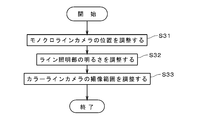
- the camera position adjustment method includes the steps of adjusting the position of the monochrome line camera, adjusting the brightness of the illumination by the line illumination unit while referring to the output from the monochrome line camera, the monochrome line camera, and Imaging a reference pattern with the plurality of color line cameras, adjusting an imaging range of the plurality of color line cameras with reference to an output from the monochrome line camera and an output from the plurality of color line cameras; Is provided.
- the connection part of the imaging range of a color line camera can be adjusted easily.
- FIG. 1 is a diagram illustrating a printing apparatus according to a first embodiment. It is a figure which shows the discharge part of a printing mechanism. It is a figure which shows an image reading apparatus. It is a figure which shows arrangement
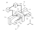
- FIG. 1 is a perspective view showing an appearance of a printing apparatus 10 according to the first embodiment of the present invention.
- the printing apparatus 10 includes a printing mechanism 11 that performs printing on printing paper 9 that is a web, a conveyance mechanism 12 that conveys the printing paper 9, an image inspection apparatus 13 that inspects an image, and a control unit 14 that controls these.
- the printing apparatus 10 performs printing of an image including variable information, so-called variable printing, and automatically inspects an image on the printing paper 9 (hereinafter referred to as “printed image”).
- the control unit 14 rasterizes data of an image to be printed (hereinafter referred to as “original image”), thereby generating data used for printing (hereinafter referred to as “original image data”).
- original image data data used for printing
- the control unit 14 also serves as an image data generation unit.
- the transport mechanism 12 transports the printing paper 9 relative to the printing mechanism 11 in the ( ⁇ Y) direction in FIG.
- the X direction, the Y direction, and the Z direction in FIG. 1 are perpendicular to each other, and the Z direction corresponds to the vertical direction.
- a plurality of rollers 121 that are each long in the X direction in FIG. 1 are arranged in the Y direction.
- a supply unit 122 that holds a roll of the printing paper 9 before printing and feeds the printing paper 9 from the roll toward the printing mechanism 11 is provided.
- a winding unit 123 that winds and holds a portion on which the printing paper 9 has been printed in a roll shape is provided.
- the printing paper 9 when the printing paper 9 is simply referred to, it means the printing paper 9 being transported (that is, the printing paper 9 on the plurality of rollers 121).
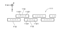
- FIG. 2 is a bottom view of one ejection unit 111 of the printing mechanism 11.
- the moving direction of the printing paper 9 with respect to the ejection unit 111 (that is, the ( ⁇ Y) direction) is shown upward.
- the printing mechanism 11 is provided with a plurality of ejection units that eject inks of cyan (C), magenta (M), yellow (Y), and black (K), respectively. Arranged in the Y direction.
- a plurality of heads 112 in the discharge unit 111 are perpendicular to the moving direction of the printing paper 9 and parallel to the printing surface of the printing paper 9 (the X direction in FIGS. 1 and 2), corresponding to the width of the printing paper 9. (Hereinafter, referred to as “width direction”), and a plurality of discharge ports 1121 are arranged on the bottom surface of each head 112 at a constant pitch in the width direction.
- the head 112 is provided with a piezoelectric element corresponding to each discharge port 1121, and a minute droplet of ink is discharged toward the printing paper 9 from each discharge port 1121 by driving the piezoelectric element.
- the distance between the two heads 112 adjacent to each other in the width direction is accurately adjusted, and all the discharge ports 1121 included in the discharge unit 111 are constant over the entire width of the print area on the printing paper 9 in the width direction. Are lined up at the pitch.
- printing is performed at high speed only when the printing paper 9 passes below the ejection unit 111 once (so-called one-pass).
- FIG. 2 only five ejection ports 1121 are shown in each head 112, but actually a large number of ejection ports 1121 are arranged.
- the head 112 may be of a type that ejects fine droplets by heating ink.
- the control unit 14 ejects ink from the heads 112 of each color according to the original image data to be printed. By performing the control, a color print image for one page is formed on a portion of the print paper 9 corresponding to one page of the printed matter.
- the image inspection device 13 is an image reading device 131 that reads a printed image of the printed paper 9 after printing (that is, a portion where printing of the printing paper 9 is completed), and an image that inspects the printed image based on the read image.
- An inspection unit 132 is provided.
- the image reading device 131 is located on the downstream side of the printing mechanism 11.
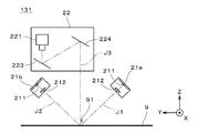
- FIG. 3 is a view of the image reading device 131 as viewed from the width direction of the printing paper 9, and shows a simplified internal configuration of the image reading device 131.
- the image reading device 131 includes a first line illumination unit 21a, a second line illumination unit 21b located on the (+ Y) side of the first line illumination unit 21a, and the first line illumination unit 21a and the second line illumination unit 21b.
- An imaging unit 22 located above is provided.
- the first line illumination unit 21a includes a plurality of light emitting diodes 211 and a lens unit 212 arranged in the X direction. Light from the plurality of light emitting diodes 211 is made uniform in the X direction, and is printed along the optical axis J1. 9 is irradiated linearly.
- the second line illumination unit 21b includes a plurality of light emitting diodes 211 and a lens unit 212, and the light from the plurality of light emitting diodes 211 is made uniform in the X direction, and the first line illumination unit along the optical axis J2.
- the same position as the position irradiated by 21a is irradiated linearly.
- the imaging unit 22 images a linear region included in the region irradiated with light by the first line illumination unit 21a and the second line illumination unit 21b.
- the entire area captured by the imaging unit 22 is referred to as an “imaging area 91”.
- the imaging area 91 includes a range in which an image is printed in the width direction.
- FIG. 4 is a diagram illustrating an arrangement of a plurality of cameras of the imaging unit 22 when viewed from the Y direction of FIG. However, the optical axis J3 in FIG. 3 is shown in a developed state.
- the imaging unit 22 includes two color line cameras 221a and 221b, one monochrome line camera 222 (shown only in FIG. 4) positioned between the color line cameras 221a and 221b, and a first mirror 223 and a second mirror 224. (Shown only in FIG. 3).
- color line cameras 221a and 221b are not distinguished from each other, they are referred to as “color line cameras 221”.
- the first mirror 223 has a strip shape long in the X direction, and is disposed below the color line camera 221 and the monochrome line camera 222.
- the second mirror 224 also has a strip shape that is long in the X direction, and is located on the ( ⁇ Y) side of the color line camera 221 and the monochrome line camera 222.
- the optical axis of the color line camera 221 and the optical axis of the monochrome line camera 222 are bent by the first mirror 223 and the second mirror 224.
- the optical axis of the color line camera 221 and the optical axis of the monochrome line camera 222 are parallel to each other.
- the optical axes of the color line camera 221 and the monochrome line camera 222 are overlapped, and are denoted by reference numeral J3.
- the color line camera 221 and the monochrome line camera 222 are arranged in the X direction, and the monochrome line camera 222 is positioned slightly above the color line camera 221.
- 4096 light receiving elements are arranged in the X direction, and the size of one light receiving element in the X direction is 10 ⁇ m.
- the focal length of the lens unit is 105 mm, and the magnification is 1 / 7.2.
- the line sensor of the monochrome line camera 222 8192 light receiving elements are arranged in the X direction, and the size of one light receiving element in the X direction is 7 ⁇ m.
- the focal length of the lens unit is 85 mm, and the magnification is 1 / 10.28.
- the working distances of the color line camera 221 and the monochrome line camera 222 are approximately the same, and the visual field size per pixel in the X direction is 72 ⁇ m.
- the resolution of the color line camera 221 in the width direction of the printing paper 9 is 1 ⁇ 2 times or less of the resolution in the width direction of the print image, thereby quickly and appropriately detecting defects in the print image. can do.
- the resolution and resolution here are the number of pixels per unit distance.
- the resolution of the monochrome line camera 222 is about the same as that of the color line camera 221.
- the aperture value and the exposure time are determined in synchronization with the change in the moving speed of the printing paper 9, and the resolution is constant even if the moving speed of the printing paper 9 varies.
- the monochrome line camera 222 has a resolution of about 128 ⁇ m in the moving direction of the printing paper 9 in order to acquire information elements described later. Therefore, when the moving speed of the printing paper 9 is 200 m / min, the line rate of the monochrome line camera 222 (number of times of imaging per unit time) is 25 kHz or more.
- the light from the imaging region 91 enters the second mirror 224 along the optical axis J3, is reflected by the second mirror 224, and is guided to the first mirror 223.
- the light reflected by the first mirror 223 enters the color line camera 221 and the monochrome line camera 222.
- the optical system between the color line camera 221 and the imaging area 91 and the optical system between the monochrome line camera 222 and the imaging area 91 share the first mirror 223 and the second mirror 224.
- the right half of the imaging area 91 of the printing paper 9 is imaged by the first color line camera 221a located on the ( ⁇ X) side. Further, the second half of the imaging area 91 is imaged by the second color line camera 221b located on the (+ X) side.
- the entire imaging region 91 is imaged by arranging the imaging range 812 of the second color line camera 221b in the longitudinal direction of the imaging range 811 of the first color line camera 221a (that is, the X direction in FIG. 4).
- the In the monochrome line camera 222, the entire imaging area 91 is an imaging range.
- the color line camera 221 and the monochrome line camera 222 repeat the imaging operation while continuously moving the printing paper 9 in the moving direction by the transport mechanism 12.
- the color image acquired by the color line camera 221 and the monochrome image acquired by the monochrome line camera 222 are output to the image inspection unit 132.
- captured images when a color image and a monochrome image are not distinguished, they are referred to as “captured images”.
- FIG. 5 is a block diagram showing a functional configuration of the image inspection unit 132.
- the image inspection unit 132 is realized by a computer and a dedicated electric circuit, but of course, the whole image inspection unit 132 may be realized by a computer or a dedicated electric circuit.
- the image inspection unit 132 includes an image composition unit 30 that combines the images from the imaging unit 22, an image comparison unit 31 that inspects the presence or absence of defects in the print image, an information reading unit 32 that acquires information elements in the print image, and various types.
- a storage unit 33 for storing information and a result output unit 34 for outputting the inspection result are provided.
- the information elements are letters and symbols such as alphabets, numerals such as Arabic numerals, or code patterns such as barcodes and two-dimensional codes.
- Character information such as customer names, receipt amounts, etc. It represents the numerical information.
- the printed image of each page printed on the printing paper 9 includes at least one information element.
- storage devices such as a semiconductor memory and a hard disk drive in the image inspection unit 132 are collectively shown as the storage unit 33.
- the information reading unit 32 includes an information image extraction unit 321, an information acquisition unit 322, and an encryption unit 323. These functions will be described later.
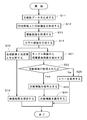
- the original image data to be printed is generated by the control unit 14 shown in FIG. 1 (step S11).
- the original image data is sent to the printing mechanism 11, and the transport mechanism 12 continuously moves the printing paper 9, while the printing mechanism 11 controls the ejection of ink of each color according to the original image data.
- a print image is formed (step S12). Then, the print image immediately after the formation is picked up by the image reading device 131, and the picked-up images are sequentially acquired (step S13). The captured image is output to the image inspection unit 132.
- the outputs from the two color line cameras 221 are synthesized to generate a color image (step S14), and the color image data 411 is stored in the storage unit 33.
- a monochrome image captured by the monochrome line camera 222 is stored in the storage unit 33 as monochrome image data 412.
- the original image data 421 is sent from the control unit 41 to the image inspection unit 132 and stored in the storage unit 33. At this time, the original image data 421 is converted from data in the CMYK color space to data in the RGB color space.
- the image comparison unit 31 compares the color image data 411 with the original image data 421 (step S15). Thereby, it is inspected whether or not the printed image has defects such as ink dripping or ink missing.
- the comparison result is stored in the storage unit 33 as inspection result data 431 (step S16). Further, it is output to the operator via a result output unit 34 such as a display unit. Note that the inspection for a color image may be performed every several lines instead of in units of pages. In the above description, for easy understanding, it is assumed that the color image data 411 and the original image data 421 are stored in the storage unit 33 and then compared by the image comparison unit 31. The comparison may be performed by directly inputting to the image comparison unit 31 in units of images.
- the information image extraction unit 321 of the information reading unit 32 extracts the part of the information element in the monochrome image as an information element image (step S21).
- Area data 422 indicating an area (range) where information elements in the original image are arranged is input to the image inspection unit 132 in advance by the operator and stored in the storage unit 33.
- the type of information element that is, whether or not it is an information element for OCR (Optical Character Recognition) or the type of code pattern
- the control unit 14 and the image inspection unit 132 may automatically generate area data 422 and data indicating the type of information element from the original image data before rasterization.
- the information acquisition unit 322 when the information element is a character, number, or symbol, character information or numerical information indicated by the information element is read from the information element image by OCR, and when the information element is a code pattern, The information element is decoded and read as character information or numerical information (step S22).
- the code pattern may be other than a barcode or a two-dimensional code.
- target information the character information or numerical information acquired from the information element image
- the target information is information expressed in a text format or markup language including personal information
- it is encrypted by the encryption unit 323 (step S23).
- the encrypted target information 432 is stored in the storage unit 33 (step S24).
- step S22 if the target information cannot be read in step S22, a number indicating the corresponding area is stored in the storage unit 33, and an error is displayed in the result output unit 34 to notify the operator (step). S25).
- a print image for a large number of pages is continuously formed on the printing paper 9, and defect inspection and acquisition of target information in the print image of each page is formed by the image inspection apparatus 13. Immediately after it is performed.
- the monochrome line camera 222 is positioned approximately at the center in the width direction of the printing paper 9, and the first color line camera 221a and the second color line camera 221b are respectively disposed on both sides of the monochrome line camera 222 in the width direction of the printing paper 9. Position. Further, a reference pattern for reference is arranged at a position to be imaged. The position of the monochrome line camera 222 is finely adjusted with reference to the image captured by the monochrome line camera 222 (step S31). Next, the brightness of the illumination by the first and second line illumination units 21a and 21b shown in FIG. 3 is adjusted with reference to the output from the monochrome line camera 222 (step S32).
- the first color line camera 221a, the second color line camera 221b, and the monochrome line camera 222 capture the reference pattern.
- X of the imaging range of the first color line camera 221a is set so that the image captured by the first color line camera 221a is the same as the right half in FIG. 4 of the pattern image captured by the monochrome line camera 222.
- the position in the direction and the Y direction is adjusted.
- the X direction of the imaging range of the second color line camera 221a and the Y direction so that the boundary between the image captured by the second color line camera 221b and the image captured by the first color line camera 221a coincide with each other.
- the position in the direction is adjusted (step S33).
- the imaging by the monochrome line camera 222 and the imaging by the color line camera 221 are performed on the same imaging area 91, illumination in imaging is performed by the common line illumination unit. be able to.
- downsizing of the image reading device 131 is realized by downsizing the line illumination unit. In-line mounting of the image inspection apparatus 13 on the printing apparatus 10 is also facilitated.
- the first mirror 223 and the second mirror 224 it is possible to reduce the height of the imaging unit 22 in the vertical direction while ensuring a working distance.
- the monochrome line camera 222 and the color line camera 221 share the first mirror 223 and the second mirror 224, the structure of the optical system can be simplified, and the image reading device 131 can be further downsized.
- the line rate of the color line camera is higher than that of the monochrome line camera (that is, the scanning cycle is short).
- the two color line cameras 221 capture an image, thereby shortening the acquisition time of the color image and improving the reading speed of the entire imaging unit 22. Therefore, the image inspection apparatus 13 is particularly suitable for a one-pass high-speed printing apparatus.
- the manufacturing cost of the image reading device 131 can be reduced.
- FIG. 8 is a diagram showing an imaging unit 22 according to another example, and the direction from the bottom to the top in FIG. 8 is the moving direction of the printing paper 9.
- the first and second color line cameras 221a and 221b and the monochrome line camera 222 are arranged in front and rear in the Y direction.
- the first color line camera 221a and the second color line camera 221b are arranged in the X direction.
- the optical axes of the color line camera 221 and the monochrome line camera 222 are shown in a developed state.
- one line illumination unit 21 indicated by a two-dot chain line is provided between the first and second color line cameras 221a and 221b and the monochrome line camera 222.
- the line illumination unit 21 has the same structure as the first line illumination unit 21 a in FIG. 3, and the light from the line illumination unit 21 is irradiated linearly over the entire width direction of the printing paper 9.
- the imaging range of the monochrome line camera 222 matches the entire linear imaging area 91 to be imaged.
- the imaging range of the first color line camera 221a is the right half of the imaging area 91 in FIG. 8, and the imaging range of the second color line camera 221b is the left half of the imaging area 91.
- the image reading device 131 is downsized by performing illumination in the imaging by the monochrome line camera 222 and the imaging by the color line camera 221 by the common line illumination unit 21.
- FIG. 9 is a diagram illustrating the imaging unit 22a of the printing apparatus according to the second embodiment.
- the first and second line illumination units 21 a and 21 b and the printing mechanism 11 are indicated by two-dot chain lines.
- double-sided printing is performed on the printing paper 9.
- a portion of the printing paper 9 whose surface is directed upward (hereinafter referred to as “first printing paper 921”) is conveyed in the ( ⁇ Y) direction on the left side of FIG. 9, and the first printing paper 921 is printed by the printing mechanism 11.
- a surface image is printed on the surface.
- the first printing paper 921 is turned upside down and returned to the (+ Y) side in FIG. 9, that is, the upstream side from the printing mechanism 11.
- second printing paper 922 the portion of the printing paper that has been returned to the upstream side is referred to as “second printing paper 922”.
- the second printing paper 922 is also conveyed in the ( ⁇ Y) direction, and an image for the back side is printed on the second printing paper 922 by the printing mechanism 11.
- the imaging unit 22a has the same configuration as that of the imaging unit 22 shown in FIGS. 3 and 4, and in FIG. 9, the optical axis is developed and simplified.
- the first color line camera 221a, the monochrome line camera 222, and the second color line camera 221b are arranged in the X direction, and the first line illumination unit 21a and the second line illumination unit 21b are arranged on both sides in the Y direction of the imaging unit 22a.
- the linear light extending in the width direction across the first printing paper 921 and the second printing paper 922 is irradiated by the first and second line illumination units 21a and 21b.
- the imaging range of the first color line camera 221a is the entire imaging area 911 extending in the width direction on the first printing paper 921
- the imaging range of the second color line camera 221b is a width on the second printing paper 922. This is the entire imaging region 912 extending in the direction.
- the imaging range of the monochrome line camera 222 includes imaging areas 911 and 912 of the first printing paper 921 and the second printing paper 922.
- the image inspecting unit 132 does not use the image compositing unit 30, and based on the color image acquired by the first color line camera 221a, the surface print image is inspected for defects and acquired by the second color line camera 221b. Based on the obtained color image, the printed image on the back side is inspected for defects (see FIG. 6: steps S13, S15, and S16). Moreover, target information is acquired from the print image printed on the surface based on the portion corresponding to the imaging region 911 on the first print sheet 921 among the monochrome images acquired by the monochrome line camera 222, and the second print sheet The target information is acquired from the print image printed on the back surface based on the portion corresponding to the imaging area 912 of 921 (see steps S21 to S25).
- the color line camera 221 and the monochrome line camera 222 perform imaging using a common line illumination unit, whereby the image reading device 131 is downsized.
- the image reading device 131 is downsized.
- the reading speed of the color line camera 221 can be ensured, and the reading speed of the entire imaging unit 22 is improved.
- the manufacturing cost of the image reading device 131 can be reduced.
- FIG. 10 is a diagram illustrating a part of the image inspection apparatus 13 of the printing apparatus according to the third embodiment.
- An information inspection unit 32a shown in FIG. 10 is provided in the image inspection unit 132 in place of the information reading unit 32 shown in FIG.
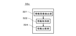
- the encryption unit 323 shown in FIG. 5 is omitted, and an information comparison unit 324 is provided. Further, instead of steps S23 and S24 in FIG. 6, steps S41 and S42 shown in FIG. 11 are executed.
- the other structure of the printing apparatus according to the third embodiment is the same as that of the printing apparatus 10 according to the first embodiment, except that the operation of the printing apparatus 10 is also inspected for target information. This is the same as in the first embodiment.
- the third embodiment first, data indicating an information element image is generated based on the original information by the control unit 14 shown in FIG. 1, and the data is included in the original image data (step S11). Then, in parallel with the printing (step S12), the original image data and the original information are stored in the storage unit 33 in FIG.
- the original information refers to character information such as a customer name and numerical information such as a receipt amount.
- the image inspection unit 132 inspects the color image, and the inspection result is stored in the storage unit 33 (steps S13 to S16).
- An information element image is cut out from the monochrome image by the information image extraction unit 321 (step S21).
- target information indicated by the information element is acquired from the information element image (step S22). If the target information cannot be acquired, an error display is performed (step S25).
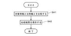
- the information comparison unit 324 compares the target information with the original information used for printing (step S41).
- the comparison result is included in the inspection result data 431 shown in FIG. 5 and stored in the storage unit 33 (step S42).
- the result output unit 34 outputs a result indicating normality to the operator when the target information and the original information completely match, and outputs a result indicating abnormality (defective) when the information does not completely match.
- the information comparison unit 324 is provided, so that the information element can be inspected in real time. Further, as in the first embodiment, the image reading apparatus 131 is downsized while improving the reading speed, and the manufacturing cost is also reduced.
- imaging may be performed by three color line cameras 221 and two monochrome line cameras 222.
- the imaging ranges of the two monochrome line cameras 222 are aligned in the longitudinal direction of the respective imaging ranges and overlap the entire imaging area 91 on the printing paper 9.
- the imaging ranges of the three color line cameras 221 are also arranged in the longitudinal direction of the respective imaging ranges and overlap the entire imaging area 91 on the printing paper 9.
- the imaging unit may be provided with a plurality of monochrome line cameras 222 and a plurality of color line cameras 221, and the number of color line cameras 221 is larger than that of the monochrome line cameras 222.
- the color line camera 221 is inexpensive and has a smaller number of pixels than that of the monochrome line camera 222.
- the total number of pixels of the color line camera 221 is preferably the same as the total number of pixels of all the monochrome line cameras 222. However, the total number of pixels need not be exactly the same.
- a part of the imaging range of the plurality of color line cameras 221 may overlap. The same applies when a plurality of monochrome line cameras are provided.
- the original image data when the defect inspection is performed, is not synthesized with the image captured by the first color line camera 221a and the image captured by the second color line camera 221b. You may compare directly with the corresponding part of. In this case, for example, the original image data is branched or divided according to the number of color line cameras from the control unit 14 and stored in the storage unit 33.
- the image inspection unit 132 may be realized by the control unit 14.
- the information element image and the part other than the information element image may be printed separately (that is, exclusively), and the information element image and the part other than the information element image are printed in an overlapping manner. May be.
- the first and second color line cameras 221a and 221b and the optical system between the print paper 9 and the optical system between the monochrome line camera 222 and the print paper 9 In addition to the two mirrors 223 and 224, other optical elements such as a lens may be shared. By sharing at least one optical element, the structure of the optical system is simplified.
- the imaging region 91 does not need to be set strictly along the width direction of the printing paper 9, and is inclined with respect to the width direction as long as the direction intersects the relative movement direction of the printing paper 9. May be.
- the ejection ports 1121 of the head 112 do not need to be strictly arranged along the width direction of the printing paper 9 and are inclined with respect to the width direction as long as they intersect the relative movement direction of the printing paper 9. May be.
- the image inspection apparatus 13 may be used in other printing apparatuses that perform printing without plate such as an electrophotographic system in addition to the ink jet printing apparatus, and the printing medium in the printing apparatus 10 is a film other than printing paper. Or a plate-like member. Further, the position of the print medium may be fixed, and the printing mechanism 11 and the image reading device 131 may move.
- Printing paper 10 Printing apparatus 11 Printing mechanism 12 Conveyance mechanism 13 Image inspection apparatus 14 Control part 21,21a, 21b Line illumination part 31 Image comparison part 33 Memory
Landscapes
- Engineering & Computer Science (AREA)
- Multimedia (AREA)
- Signal Processing (AREA)
- Analytical Chemistry (AREA)
- Physics & Mathematics (AREA)
- Health & Medical Sciences (AREA)
- Life Sciences & Earth Sciences (AREA)
- Chemical & Material Sciences (AREA)
- Textile Engineering (AREA)
- Biochemistry (AREA)
- General Health & Medical Sciences (AREA)
- General Physics & Mathematics (AREA)
- Immunology (AREA)
- Pathology (AREA)
- Investigating Materials By The Use Of Optical Means Adapted For Particular Applications (AREA)
- Image Input (AREA)
Abstract
画像読取装置(131)は、2つのカラーラインカメラ(221a,221b)、および、1つのモノクロラインカメラ(222)を備え、印刷用紙(9)上の線状の撮像領域(91)を撮像する。撮像領域(91)には、ライン照明部(21,21a,21b)により照明光が照射される。印刷画像が検査される際には、カラーラインカメラ(221a,221b)により撮像されたカラー画像と元画像とが比較される。また、モノクロラインカメラ(222)により撮像されたモノクロ画像中のバーコード等の情報要素画像が切り出され、情報要素が示す対象情報が取得される。画像読取装置(131)では、カラー画像およびモノクロ画像が同一の撮像領域(91)から取得されるため、ライン照明部(21,21a,21b)が小型化され、画像読取装置(131)の小型化が実現される。
Description
本発明は、印刷媒体に印刷された画像を読み取る画像読取装置に関する。
近年、インクジェット方式の印刷装置を用いて、ダイレクトメール等の高速印刷が行われている。このような印刷装置では、ロール紙である印刷用紙の各ページに相当する部位に個別の情報(いわゆる、可変情報)が印刷される。インクジェット方式の印刷装置により印刷された画像(以下、「印刷画像」という。)では、印刷装置のヘッドが印刷媒体に擦れてインク垂れが発生したり、ノズル詰まりによるインク抜けが発生することがある。そこで、印刷装置には、このような欠陥を検出する検査装置が搭載される。検査装置は、例えば、カラー印刷の場合、カラーラインカメラを用いて印刷画像を撮像し、撮像画像に基づいて欠陥を検出する。
また、印刷装置では、文字や数字、バーコードあるいは2次元コード等の情報要素が、文字情報または数値情報を表すものとして印刷されることがあり、印刷された画像中のこれらの情報要素を検査することが提案されている。例えば特開2006-79571号公報では、用紙上に印刷された印刷文字を認識デコードして文字コードに変換し、印刷すべき文字コードと比較照合して良否判定を行う手法が開示されている。特開2001-277676号公報に開示される画像認識装置では、電話番号等が印刷された用紙上の3箇所の検証フィールドを3つのOCR(optcal character reader)カメラにより撮像し、印字品質の良否判断が行われる。
近年、印刷されたカラー画像の検査と印刷された情報の検査とを同時に行うことが要望されている。このような場合に、検査装置にラインレートが低い安価なカラーラインカメラを利用すると、高速に移動する印刷媒体上において1回の撮像動作にて撮像される範囲が広がってしまい、印刷媒体の移動方向に圧縮された状態にて撮像画像が取得される。その結果、例えば、印刷媒体の移動方向にバーが並ぶ1次元バーコードが印刷画像中に存在すると、1次元バーコードは、隣接するバーが1つに重なった状態にて撮像され、デコード処理を行うことができない。この対策として、カラー画像の検査とは別に、照明系を含むデコード処理用の高速なモノクロラインカメラのユニットを設けると、検査装置が大型化してしまい、インライン化が困難となる。
本発明は、相対的に移動する印刷媒体に印刷された画像を読み取る画像読取装置に向けられており、当該画像読取装置を小型化することを目的としている。
本発明に係る画像読取装置は、相対的に移動する印刷媒体に印刷された画像を読み取る画像読取装置であって、印刷媒体上において前記印刷媒体の相対移動方向に交差する方向に伸びる線状の撮像領域に向けて光を照射するライン照明部と、前記撮像領域を撮像する1つのモノクロラインカメラ、または、各カメラの撮像範囲が、前記撮像範囲の長手方向に並ぶことにより前記撮像領域を撮像する複数のモノクロラインカメラと、各カメラの撮像範囲が長手方向に並ぶことにより前記撮像領域を撮像する複数のカラーラインカメラとを備える。前記複数のカラーラインカメラの数が、前記1つまたは複数のモノクロラインカメラの数よりも多く、カラーラインカメラの画素数が、モノクロラインカメラの画素数よりも少ない。これにより、画像読取装置を小型化することができる。
好ましくは、前記1つまたは複数のモノクロラインカメラの光軸および前記複数のカラーラインカメラの光軸が平行であり、前記1つまたは複数のモノクロラインカメラと前記印刷媒体との間の光学系と、前記複数のカラーラインカメラと前記印刷媒体との間の光学系とが、少なくとも1つの光学要素を共有する。これにより、光学系の構造を簡素化することができる。
本発明は、また、相対的に移動する印刷媒体に印刷された画像を検査する画像検査装置にも向けられている。画像検査装置は、前記画像読取装置と、前記1つまたは複数のモノクロラインカメラにて取得された画像から、少なくとも1つの文字、数字もしくは記号またはバーコードパターンである情報要素の部位である情報要素画像を抽出する情報画像抽出部と、前記情報要素画像から前記情報要素が示す文字情報または数値情報である対象情報を取得する情報取得部と、前記対象情報を保存する記憶部と、前記複数のカラーラインカメラにて取得された画像と、印刷に用いられたデータが示す画像とを比較する画像比較部とを備える。
好ましくは、前記1つまたは複数のモノクロラインカメラが、1つのモノクロラインカメラである。これにより、複数のモノクロラインカメラからの画像を合成する必要がなくなり、情報要素画像を容易に取得することができる。
本発明は、また、画像検査装置を備える印刷装置にも向けられている。印刷装置は、印刷媒体を搬送する搬送機構と、前記印刷媒体に印刷を行う印刷機構と、をさらに備える。
本発明は、また、相対的に移動する印刷媒体に印刷された画像を読み取る画像読取装置において、複数のカメラの位置を調整するカメラ位置調整方法にも向けられている。前記画像読取装置が、印刷媒体上において前記印刷媒体の相対移動方向に交差する方向に伸びる線状の撮像領域に向けて光を照射するライン照明部と、前記撮像領域を撮像する1つのモノクロラインカメラと、各カメラの撮像範囲が長手方向に並ぶことにより前記撮像領域を撮像する複数のカラーラインカメラとを備える。
前記カメラ位置調整方法は、前記モノクロラインカメラの位置を調整する工程と、前記モノクロラインカメラからの出力を参照しつつ前記ライン照明部による照明の明るさを調整する工程と、前記モノクロラインカメラおよび前記複数のカラーラインカメラにて参照パターンを撮像し、前記モノクロラインカメラからの出力および前記複数のカラーラインカメラからの出力を参照して、前記複数のカラーラインカメラの撮像範囲を調整する工程とを備える。これにより、カラーラインカメラの撮像範囲のつなぎ部を容易に調整することができる。
上述の目的および他の目的、特徴、態様および利点は、添付した図面を参照して以下に行うこの発明の詳細な説明により明らかにされる。
図1は、本発明の第1の実施の形態に係る印刷装置10の外観を示す斜視図である。以下の説明において、インクジェット方式にて媒体上に画像を形成することを適宜、「印刷」と呼ぶ。印刷装置10は、ウェブである印刷用紙9に印刷を行う印刷機構11、印刷用紙9を搬送する搬送機構12、画像を検査する画像検査装置13、および、これらを制御する制御部14を備える。印刷装置10では、可変情報を含む画像の印刷、いわゆる、バリアブル印刷が行われるとともに、印刷用紙9上の画像(以下、「印刷画像」という。)が自動検査される。制御部14では、印刷対象の画像(以下、「元画像」という。)のデータがラスタライズされることにより、印刷に用いられるデータ(以下、「元画像データ」という。)が生成される。このように、制御部14は、画像データ生成部としての役割を兼ねる。
搬送機構12は、印刷機構11に対して印刷用紙9を図1中の(-Y)方向に相対的に搬送する。なお、図1中のX方向、Y方向およびZ方向は互いに垂直であり、Z方向が上下方向に対応する。搬送機構12では、それぞれが図1中のX方向に長い複数のローラ121がY方向に配列される。複数のローラ121の(+Y)側には、印刷前の印刷用紙9のロールを保持するとともに当該ロールから印刷用紙9を印刷機構11に向けて送り出す供給部122が設けられる。複数のローラ121の(-Y)側には、印刷用紙9の印刷が行われた部位をロール状に巻き取って保持する巻取部123が設けられる。以下の説明では、単に印刷用紙9という場合は搬送途上の印刷用紙9(すなわち、複数のローラ121上の印刷用紙9)を意味するものとする。
印刷機構11は、搬送機構12の上方に配置され、搬送機構12を跨ぐようにして基台15に設けられたフレーム151に固定される。図2は印刷機構11の1つの吐出部111の底面図であり、図2では、印刷用紙9の吐出部111に対する移動方向(すなわち、(-Y)方向)を上向きに示している。実際には、印刷機構11には、シアン(C)、マゼンタ(M)、イエロー(Y)、ブラック(K)の色のインクをそれぞれ吐出する複数の吐出部が設けられ、複数の吐出部はY方向に配列される。吐出部111には複数のヘッド112が印刷用紙9の移動方向に垂直かつ印刷用紙9の印刷面に平行な方向(図1および図2中のX方向であり、印刷用紙9の幅に対応する方向であるため、以下、「幅方向」という。)に千鳥状に配列されており、各ヘッド112の底面には、複数の吐出口1121が幅方向に一定のピッチにて配列形成される。
ヘッド112には各吐出口1121に対応して圧電素子が設けられており、圧電素子を駆動することにより各吐出口1121からインクの微小液滴が印刷用紙9に向けて吐出される。幅方向に関して互いに隣接する2つのヘッド112間の距離は精度よく調整されており、吐出部111に含まれる全ての吐出口1121は幅方向に関して印刷用紙9上の印刷領域の幅全体に亘って一定のピッチにて並んでいる。印刷装置10では、印刷用紙9が吐出部111の下方を1回通過するのみにて(いわゆる、ワンパスにて)高速に印刷が行われる。図2では、各ヘッド112に5個の吐出口1121のみが示されているが、実際には多数の吐出口1121が配列される。ヘッド112はインクの加熱により微小液滴を吐出するタイプのものであってもよい。
図1の印刷装置10では、搬送機構12による印刷用紙9の(-Y)方向への移動に並行して、制御部14が印刷対象の元画像データに従って、各色のヘッド112からのインクの吐出制御を行うことにより、印刷物の1ページ分に相当する印刷用紙9上の部位に1ページ分のカラーの印刷画像が形成される。
画像検査装置13は、印刷後の印刷用紙9(すなわち、印刷用紙9の印刷が終了した部位)の印刷画像を読み取る画像読取装置131、および、読み取られた画像に基づいて印刷画像を検査する画像検査部132を備える。画像読取装置131は、印刷機構11よりも下流側に位置する。
図3は、画像読取装置131を印刷用紙9の幅方向から見た図であり、画像読取装置131の内部構成を簡略化して示している。画像読取装置131は、第1ライン照明部21a、第1ライン照明部21aの(+Y)側に位置する第2ライン照明部21b、並びに、第1ライン照明部21aおよび第2ライン照明部21bの上方に位置する撮像部22を備える。第1ライン照明部21aは、X方向に配列された複数の発光ダイオード211およびレンズユニット212を備え、複数の発光ダイオード211からの光はX方向に関して均一化され、光軸J1に沿って印刷用紙9上に線状に照射される。同様に、第2ライン照明部21bは、複数の発光ダイオード211およびレンズユニット212を備え、複数の発光ダイオード211からの光はX方向に関して均一化され、光軸J2に沿って第1ライン照明部21aにより照射される位置と同じ位置に線状に照射される。撮像部22では、第1ライン照明部21aおよび第2ライン照明部21bにより光が照射される領域に含まれる線状の領域を撮像する。以下、撮像部22が撮像する領域全体を「撮像領域91」と呼ぶ。撮像領域91は、幅方向において、画像が印刷される範囲を含む。
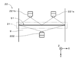
図4は、図3のY方向から見た場合の撮像部22の複数のカメラの配置を示す図である。ただし、図3の光軸J3を展開した状態にて示している。撮像部22は、2つのカラーラインカメラ221a,221b、カラーラインカメラ221a,221bの間に位置する1つのモノクロラインカメラ222(図4のみに図示)、並びに、第1ミラー223および第2ミラー224(図3のみに図示)を備える。以下の説明では、カラーラインカメラ221a,221bを区別しない場合は、「カラーラインカメラ221」といい、区別する場合は、「第1カラーラインカメラ221a」、「第2カラーラインカメラ221b」という。
第1ミラー223はX方向に長い帯状であり、カラーラインカメラ221およびモノクロラインカメラ222の下方に配置される。第2ミラー224もX方向に長い帯状であり、カラーラインカメラ221およびモノクロラインカメラ222の(-Y)側に位置する。図3に示すように、撮像部22では、カラーラインカメラ221の光軸、および、モノクロラインカメラ222の光軸は、第1ミラー223および第2ミラー224により折り曲げられた状態となっている。また、カラーラインカメラ221の光軸、および、モノクロラインカメラ222の光軸は、互いに平行である。図3では、カラーラインカメラ221およびモノクロラインカメラ222の光軸は重なっており、符号J3を付している。
図4に示すように、カラーラインカメラ221およびモノクロラインカメラ222はX方向に配列され、モノクロラインカメラ222は、カラーラインカメラ221よりも僅かに上側に位置する。カラーラインカメラ221のラインセンサには、4096個の受光素子がX方向に配列され、1つの受光素子のX方向の大きさは10μmである。また、レンズユニットの焦点距離は105mmであり、倍率は1/7.2である。
モノクロラインカメラ222のラインセンサには、8192個の受光素子がX方向に配列され、1つの受光素子のX方向の大きさは7μmである。レンズユニットの焦点距離は85mmであり、倍率は1/10.28である。カラーラインカメラ221およびモノクロラインカメラ222のワーキングディスタンスは同程度であり、X方向におけるそれぞれの1画素当たりの視野サイズは72μmである。撮像部22では、印刷用紙9の幅方向におけるカラーラインカメラ221の分解能が、印刷画像の幅方向における解像度の1/2倍以下であり、これにより、印刷画像中の欠陥を迅速かつ適切に検出することができる。なお、ここでの分解能および解像度は、単位距離当たりの画素数である。モノクロラインカメラ222の分解能は、カラーラインカメラ221と同程度である。
カラーラインカメラ221では、印刷用紙9の移動速度の変化に同期して絞り値および露出時間が決定され、印刷用紙9の移動速度が変動しても分解能が一定とされる。モノクロラインカメラ222においても同様である。モノクロラインカメラ222としては、後述の情報要素の取得のために、印刷用紙9の移動方向における分解能は128μm程度とされる。したがって、印刷用紙9の移動速度が200m/minである場合、モノクロラインカメラ222のラインレート(単位時間当たりの撮像回数)は25kHz以上となる。
撮像領域91からの光は、光軸J3に沿って第2ミラー224へと入射し、第2ミラー224にて反射されて第1ミラー223へと導かれる。第1ミラー223にて反射された光は、カラーラインカメラ221およびモノクロラインカメラ222に入射する。このように、カラーラインカメラ221と撮像領域91との間の光学系と、モノクロラインカメラ222と撮像領域91との間の光学系とは、第1ミラー223および第2ミラー224を共有する。
図4に示すように、(-X)側に位置する第1カラーラインカメラ221aにより、印刷用紙9の撮像領域91の右半分が撮像される。また、(+X)側に位置する第2カラーラインカメラ221bにより、撮像領域91の左半分が撮像される。撮像部22では、第1カラーラインカメラ221aの撮像範囲811の長手方向(すなわち、図4におけるX方向)に第2カラーラインカメラ221bの撮像範囲812が並ぶことにより、撮像領域91全体が撮像される。モノクロラインカメラ222では、撮像領域91全体が撮像範囲となる。
図1に示す印刷装置10では、搬送機構12により印刷用紙9を移動方向に連続的に移動しつつカラーラインカメラ221およびモノクロラインカメラ222が撮像動作を繰り返す。カラーラインカメラ221により取得されたカラー画像およびモノクロラインカメラ222により取得されたモノクロ画像は画像検査部132に出力される。以下の説明では、カラー画像およびモノクロ画像を区別しないときは、「撮像画像」という。
図5は画像検査部132の機能構成を示すブロック図である。本実施の形態では、画像検査部132はコンピュータおよび専用の電気的回路により実現されるが、もちろん、画像検査部132の全部がコンピュータまたは専用の電気的回路により実現されてもよい。画像検査部132は、撮像部22からの画像を合成する画像合成部30、印刷画像中の欠陥の有無を検査する画像比較部31、印刷画像中の情報要素を取得する情報読取部32、各種情報を記憶する記憶部33、並びに、検査結果を出力する結果出力部34を備える。ここで、情報要素とは、アルファベット等の文字や記号、もしくは、アラビア数字等の数字、または、バーコードや2次元コード等のコードパターンであり、顧客の名称等の文字情報や、領収金額等の数値情報を表すものである。印刷用紙9に印刷された各ページの印刷画像には、少なくとも1つの情報要素が含まれる。図5では、画像検査部132内の半導体メモリやハードディスク駆動装置等の記憶装置をまとめて記憶部33として示している。
情報読取部32は、情報画像抽出部321、情報取得部322および暗号化部323を備える。これらの機能については後述する。
次に、印刷装置10が印刷用紙9上に画像を印刷しつつ印刷画像を検査する動作について図6を参照して説明する。まず、図1に示す制御部14にて、印刷対象の元画像データが生成される(ステップS11)。
元画像データは印刷機構11に送られ、搬送機構12が印刷用紙9を連続的に移動しつつ、印刷機構11が元画像データに従って各色のインクの吐出を制御することにより、印刷用紙9上に印刷画像が形成される(ステップS12)。そして、画像読取装置131により形成直後の印刷画像が撮像され、撮像画像が順次取得される(ステップS13)。撮像画像は、画像検査部132へと出力される。
画像検査部132の画像合成部30では、2つのカラーラインカメラ221からの出力が合成されてカラー画像が生成され(ステップS14)、カラー画像データ411が記憶部33に記憶される。モノクロラインカメラ222により撮像されたモノクロ画像は、記憶部33にモノクロ画像データ412として記憶される。一方、印刷動作に並行して、制御部41から元画像データ421が画像検査部132へと送られ、記憶部33に記憶される。このとき、元画像データ421は、CMYK色空間からRGB色空間のデータへと変換される。
次に、画像比較部31にて、カラー画像データ411が元画像データ421と比較される(ステップS15)。これにより、印刷画像がインク垂れやインク抜け等の欠陥を有するか否かが検査される。比較結果は、検査結果データ431として記憶部33に記憶される(ステップS16)。また、表示部等の結果出力部34を介して操作者に向けて出力される。なお、カラー画像に対する検査は、ページ単位ではなく、数ライン分毎に行われてもよい。上記説明では、理解を容易とするために、カラー画像データ411および元画像データ421が記憶部33に記憶されてから画像比較部31にて比較されるものとしているが、これらの画像データはライン画像単位で画像比較部31に直接入力されて比較が行われてもよい。
カラー画像の検査に並行して、情報読取部32の情報画像抽出部321では、モノクロ画像中の情報要素の部位を情報要素画像として抽出する(ステップS21)。画像検査部132には、予め操作者により、元画像中の情報要素が配置される領域(範囲)を示す領域データ422が入力されており、記憶部33に記憶されている。なお、正確には、情報要素の種類(すなわち、OCR(Optical Character Recognition)用の情報要素であるか否か、または、コードパターンの種別)も記憶されている。制御部14や画像検査部132では、ラスタライズ前の元画像のデータから領域データ422や情報要素の種類を示すデータが自動的にて生成されてもよい。
情報取得部322では、情報要素が文字、数字または記号である場合には、情報要素画像からOCRにより情報要素が示す文字情報または数値情報が読み取られ、情報要素がコードパターンである場合には、情報要素がデコードされて文字情報または数値情報として読み取られる(ステップS22)。コードパターンは、バーコードや2次元コード以外であってもよい。
以下、情報要素画像から取得された文字情報または数値情報を「対象情報」と呼ぶ。本実施の形態では、対象情報は個人情報を含むテキスト形式またはマークアップ言語にて表現された情報であるため、暗号化部323により暗号化される(ステップS23)。暗号化された対象情報432は記憶部33に保存される(ステップS24)。
一方、ステップS22にて対象情報が読取不能であった場合、対応する領域を示す番号等が記憶部33に保存され、結果出力部34にエラーが表示されて操作者へと通知される(ステップS25)。
印刷装置10における印刷動作では、印刷用紙9上に多数ページ分の印刷画像が連続的に形成され、画像検査装置13にて、各ページの印刷画像中の欠陥の検査および対象情報の取得が形成直後に連続的に行われる。
次に、撮像部22の組み立てにおけるカラーラインカメラ221およびモノクロラインカメラ222の位置を調整する手法について図7を参照しつつ説明する。まず、モノクロラインカメラ222を印刷用紙9の幅方向におけるおよそ中央に位置させ、第1カラーラインカメラ221aおよび第2カラーラインカメラ221bをそれぞれ、印刷用紙9の幅方向におけるモノクロラインカメラ222の両側に位置させる。さらに、撮像すべき位置に参照用の参照パターンを配置する。モノクロラインカメラ222にて撮像された画像を参照しつつモノクロラインカメラ222の位置が微調整される(ステップS31)。次に、モノクロラインカメラ222からの出力を参照しつつ図3に示す第1および第2ライン照明部21a,21bによる照明の明るさが調整される(ステップS32)。
照明の調整が完了すると、第1カラーラインカメラ221aおよび第2カラーラインカメラ221b並びにモノクロラインカメラ222にて参照パターンを撮像する。そして、第1カラーラインカメラ221aにより撮像された画像が、モノクロラインカメラ222により撮像されたパターンの画像の図4における右半分と同じとなるように、第1カラーラインカメラ221aの撮像範囲のX方向およびY方向における位置が調整される。次に、第2カラーラインカメラ221bにより撮像された画像と第1カラーラインカメラ221aにより撮像された画像との境界が一致するように、第2カラーラインカメラ221aの撮像範囲ののX方向およびY方向における位置が調整される(ステップS33)。
上記手法では、第1および第2カラーラインカメラ221a,221bおよびモノクロラインカメラ222からの出力を参照して、第1および第2カラーラインカメラ221a,221bの2つの撮像範囲を調整することにより、当該2つの撮像範囲のつなぎ部が容易に調整される。
以上に説明したように、印刷装置10では、モノクロラインカメラ222による撮像とカラーラインカメラ221による撮像が同一の撮像領域91に対して行われるため、撮像における照明を共通のライン照明部にて行うことができる。その結果、ライン照明部の小型化により画像読取装置131の小型化が実現される。印刷装置10への画像検査装置13のインライン搭載も容易となる。第1ミラー223および第2ミラー224が設けられることにより、ワーキングディスタンスを確保しつつ撮像部22の上下方向における高さを低くすることができる。また、モノクロラインカメラ222およびカラーラインカメラ221が第1ミラー223および第2ミラー224を共有することにより、光学系の構造を簡素化することができ、画像読取装置131がより小型化される。
通常、同じ画素数の場合、モノクロラインカメラよりもカラーラインカメラの方がラインレートが高い(すなわち、走査周期が短い)。しかし、画像読取装置131では、2つのカラーラインカメラ221にて撮像が行われることにより、カラー画像の取得時間が短縮され、撮像部22全体の読取速度が向上される。したがって、画像検査装置13は、ワンパス方式の高速印刷装置に特に適している。また、画素数の少ない安価なカラーラインカメラ221を用いることにより、画像読取装置131の製造コストが削減される。
複数のラインカメラにて印刷画像中の情報要素に対応する部位を分割して撮像する場合、複数の画像を精度よく位置合わせして合成する必要がある。画像検査部132では、1つのモノクロラインカメラ222にてモノクロ画像が取得されるため、画像の合成処理が不要となる。これにより、情報要素画像を容易に取得することができる。
図8は、他の例に係る撮像部22を示す図であり、図8において下から上に向かう方向が、印刷用紙9の移動方向である。撮像部22では、第1および第2カラーラインカメラ221a,221bとモノクロラインカメラ222とが、Y方向における前後に配置される。また、第1カラーラインカメラ221aおよび第2カラーラインカメラ221bは、X方向に並ぶ。図8では、カラーラインカメラ221およびモノクロラインカメラ222の光軸を展開した状態にて示している。第1および第2カラーラインカメラ221a,221bとモノクロラインカメラ222との間には、二点差線にて示す1つのライン照明部21が設けられる。ライン照明部21は、図3の第1ライン照明部21aと同様の構造であり、ライン照明部21からの光は、印刷用紙9の幅方向全体に亘って線状に照射される。
図4の場合と同様に、モノクロラインカメラ222の撮像範囲は、撮像すべき線状の撮像領域91の全体と一致する。第1カラーラインカメラ221aの撮像範囲は、撮像領域91の図8における右半分であり、第2カラーラインカメラ221bの撮像範囲は、撮像領域91の左半分である。図8に示す撮像部22においても、モノクロラインカメラ222による撮像とカラーラインカメラ221による撮像における照明が、共通のライン照明部21にて行われることにより、画像読取装置131が小型化される。
図9は、第2の実施の形態に係る印刷装置の撮像部22aを示す図である。図9では、第1および第2ライン照明部21a,21b並びに印刷機構11を二点差線にて示している。第2の実施の形態に係る印刷装置では、印刷用紙9に対して両面印刷が行われる。印刷用紙9は、表面を上方に向けた部位(以下、「第1印刷用紙921」という。)が、図9の左側において(-Y)方向に搬送され、印刷機構11により第1印刷用紙921に表面用の画像が印刷される。第1印刷用紙921は、表裏が反転され、図9における(+Y)側、すなわち、印刷機構11よりも上流側に戻される。以下、上流側に戻された後の印刷用紙の部位を「第2印刷用紙922」という。第2印刷用紙922も(-Y)方向に搬送され、第2印刷用紙922には、印刷機構11により裏面用の画像が印刷される。
撮像部22aは、図3および図4に示す撮像部22と同様の構成であり、図9では、光軸を展開して簡略化して示している。第1カラーラインカメラ221a、モノクロラインカメラ222および第2カラーラインカメラ221bはX方向に配置され、撮像部22aのY方向における両側に第1ライン照明部21aおよび第2ライン照明部21bが配置される。撮像部22aでは、モノクロラインカメラ222よりも画素数が少ない第1および第2カラーラインカメラ221a,221bが利用される。
第1および第2ライン照明部21a,21bにより、第1印刷用紙921および第2印刷用紙922を跨いで幅方向に伸びる線状の光が照射される。第1カラーラインカメラ221aの撮像範囲は、第1印刷用紙921上にて幅方向に伸びる撮像領域911全体であり、第2カラーラインカメラ221bの撮像範囲は、第2印刷用紙922上にて幅方向に伸びる撮像領域912全体である。モノクロラインカメラ222の撮像範囲は、第1印刷用紙921および第2印刷用紙922の撮像領域911,912を含む。
画像検査部132では、画像合成部30は利用されず、第1カラーラインカメラ221aにより取得されたカラー画像に基づいて、表面の印刷画像の欠陥が検査され、第2カラーラインカメラ221bにより取得されたカラー画像に基づいて、裏面の印刷画像の欠陥が検査される(図6:ステップS13,S15,S16参照)。また、モノクロラインカメラ222により取得されたモノクロ画像のうち、第1印刷用紙921上の撮像領域911に対応する部分に基づいて表面に印刷された印刷画像から対象情報が取得され、第2印刷用紙921の撮像領域912に対応する部分に基づいて裏面に印刷された印刷画像から対象情報が取得される(ステップS21~S25参照)。
第2の実施の形態においても、カラーラインカメラ221およびモノクロラインカメラ222が、共通のライン照明部を利用して撮像を行うことにより、画像読取装置131が小型化される。2つのカラーラインカメラ221が設けられることにより、カラーラインカメラ221の読取速度を確保することができ、撮像部22全体の読取速度が向上される。画素数の少ない安価なカラーラインカメラ221を用いることにより、画像読取装置131の製造コストが削減される。
図10は、第3の実施の形態に係る印刷装置の画像検査装置13の一部を示す図である。図10に示す情報検査部32aは、図5に示す情報読取部32に代えて画像検査部132に設けられる。情報検査部32aでは、図5に示す暗号化部323が省略され、情報比較部324が設けられる。また、図6のステップS23,S24に代えて、図11に示すステップS41,S42が実行される。第3の実施の形態に係る印刷装置の他の構造は、第1の実施の形態に係る印刷装置10と同様であり、印刷装置10の動作も対象情報の検査が行われるという点を除いて第1の実施の形態と同様である。
第3の実施の形態では、まず、図1に示す制御部14にて、元情報に基づいて情報要素画像を示すデータが生成され、当該データが元画像データに含められる(ステップS11)。そして、印刷(ステップS12)と並行して元画像データおよび元情報が図5の記憶部33に記憶される。ここで、元情報とは、顧客の名称等の文字情報や、領収金額等の数値情報をいう。
画像読取装置131にて印刷画像が撮像されると、画像検査部132では、カラー画像の検査が行われ、検査結果が記憶部33に保存される(ステップS13~S16)。モノクロ画像からは、情報画像抽出部321にて情報要素画像が切り出され(ステップS21)。情報取得部322にて、情報要素画像から、情報要素が示す対象情報が取得される(ステップS22)。対象情報が取得できない場合はエラー表示が行われる(ステップS25)。
対象情報が取得された場合は、情報比較部324において、対象情報が、印刷に用いられた元情報と比較される(ステップS41)。比較結果は、図5に示す検査結果データ431に含められて記憶部33に記憶される(ステップS42)。結果出力部34は、対象情報と元情報とが完全に一致する場合に正常を示す結果を操作者に向けて出力し、完全には一致しない場合に異常(不良)を示す結果を出力する。
第3の実施の形態では、情報比較部324が設けられることにより、情報要素の検査をリアルタイムにて行うことができる。また、第1の実施の形態と同様に、読取速度を向上しつつ画像読取装置131が小型化され、製造コストも削減される。
以上、本発明の実施の形態について説明したが、本発明は、上記実施の形態に限定されるものではなく、様々な変更が可能である。例えば、図12に示すように、3つのカラーラインカメラ221および2つのモノクロラインカメラ222により、撮像が行われてもよい。2つのモノクロラインカメラ222の撮像範囲は、それぞれの撮像範囲の長手方向に並び、印刷用紙9上の撮像領域91全体と重なる。3つのカラーラインカメラ221の撮像範囲も、それぞれの撮像範囲の長手方向に並び、印刷用紙9上の撮像領域91全体と重なる。このように、撮像部では、複数のモノクロラインカメラ222、および、複数のカラーラインカメラ221が設けられてよく、カラーラインカメラ221の数はモノクロラインカメラ222よりも多くされる。また、カラーラインカメラ221は、画素数がモノクロラインカメラ222の画素数よりも少ない安価なものが利用される。
撮像部では、カラーラインカメラ221の総画素数は、好ましくは、全てのモノクロラインカメラ222の総画素数と同じとされる。ただし、総画素数は厳密に同じである必要はない。
上記実施の形態では、複数のカラーラインカメラ221の撮像範囲の一部が重複していてもよい。複数のモノクロラインカメラが設けられる場合も同様である。
上記第1の実施の形態では、欠陥検査が行われる際に、第1カラーラインカメラ221aにて撮像された画像を第2カラーラインカメラ221bにて撮像された画像と合成することなく元画像データの対応する部分と直接比較してもよい。この場合、例えば、制御部14から元画像データがカラーラインカメラの台数に応じて分岐または分割されて記憶部33に保存される。
画像検査部132は、制御部14にて実現されてもよい。上記実施の形態では、情報要素画像と情報要素画像以外の部位とが分離して(すなわち、排他的に)印刷されてもよく、情報要素画像と情報要素画像以外の部位とが重なって印刷されてもよい。
上記実施の形態では、第1および第2カラーラインカメラ221a,221bと印刷用紙9との間の光学系と、モノクロラインカメラ222と印刷用紙9との間の光学系とにおいて、第1および第2ミラー223,224以外にレンズ等の他の光学要素が共有されてもよい。少なくとも1つの光学要素が共有されることにより、光学系の構造が簡素化される。
印刷装置10では、撮像領域91は厳密に印刷用紙9の幅方向に沿って設定される必要はなく、印刷用紙9の相対移動方向に対して交差する方向であれば、幅方向に対して傾斜してもよい。また、ヘッド112の吐出口1121も厳密に印刷用紙9の幅方向に沿って配列される必要はなく、印刷用紙9の相対移動方向に対して交差する方向であれば、幅方向に対して傾斜してもよい。画像検査装置13は、インクジェット方式の印刷装置以外に電子写真方式等の無版にて印刷を行う他の印刷装置に利用されてもよく、印刷装置10における印刷媒体は、印刷用紙以外に、フィルムや板状の部材等であってもよい。さらに、印刷媒体の位置が固定され、印刷機構11および画像読取装置131が移動してもよい。
発明を詳細に描写して説明したが、既述の説明は例示的であって限定的なものではない。したがって、本発明の範囲を逸脱しない限り、多数の変形や態様が可能であるといえる。
9 印刷用紙
10 印刷装置
11 印刷機構
12 搬送機構
13 画像検査装置
14 制御部
21,21a,21b ライン照明部
31 画像比較部
33 記憶部
34 結果出力部
91,911,912 撮像領域
112 ヘッド
122 供給部
123 巻取部
131 画像読取装置
221,221a,221b カラーラインカメラ
222 モノクロラインカメラ
321 情報画像抽出部
322 情報取得部
323 暗号化部
324 情報比較部
1121 吐出口
J1~J3 光軸
10 印刷装置
11 印刷機構
12 搬送機構
13 画像検査装置
14 制御部
21,21a,21b ライン照明部
31 画像比較部
33 記憶部
34 結果出力部
91,911,912 撮像領域
112 ヘッド
122 供給部
123 巻取部
131 画像読取装置
221,221a,221b カラーラインカメラ
222 モノクロラインカメラ
321 情報画像抽出部
322 情報取得部
323 暗号化部
324 情報比較部
1121 吐出口
J1~J3 光軸
Claims (11)
- 相対的に移動する印刷媒体(9)に印刷された画像を読み取る画像読取装置(131)であって、
印刷媒体上において前記印刷媒体の相対移動方向に交差する方向に伸びる線状の撮像領域(91,911,912)に向けて光を照射するライン照明部(21,21a,21b)と、
前記撮像領域を撮像する1つのモノクロラインカメラ(222)、または、各カメラの撮像範囲が、前記撮像範囲の長手方向に並ぶことにより前記撮像領域を撮像する複数のモノクロラインカメラ(222)と、
各カメラの撮像範囲が長手方向に並ぶことにより前記撮像領域を撮像する複数のカラーラインカメラ(221,221a,221b)と、
を備え、
前記複数のカラーラインカメラの数が、前記1つまたは複数のモノクロラインカメラの数よりも多く、カラーラインカメラの画素数が、モノクロラインカメラの画素数よりも少ない。 - 請求項1に記載の画像読取装置であって、
前記1つまたは複数のモノクロラインカメラの光軸および前記複数のカラーラインカメラの光軸(J3)が平行であり、前記1つまたは複数のモノクロラインカメラと前記印刷媒体との間の光学系と、前記複数のカラーラインカメラと前記印刷媒体との間の光学系とが、少なくとも1つの光学要素(223,224)を共有する。 - 相対的に移動する印刷媒体に印刷された画像を検査する画像検査装置(13)であって、
請求項1または2に記載の画像読取装置と、
前記1つまたは複数のモノクロラインカメラにて取得された画像から、少なくとも1つの文字、数字もしくは記号またはバーコードパターンである情報要素の部位である情報要素画像を抽出する情報画像抽出部(321)と、
前記情報要素画像から前記情報要素が示す文字情報または数値情報である対象情報を取得する情報取得部(322)と、
前記対象情報を保存する記憶部(33)と、
前記複数のカラーラインカメラにて取得された画像と、印刷に用いられたデータが示す画像とを比較する画像比較部(31)と、
を備える。 - 請求項3に記載の画像検査装置であって、
前記対象情報を暗号化する暗号化部(323)をさらに備え、
前記対象情報が、テキスト形式またはマークアップ言語にて表現され、前記記憶部に暗号化された前記対象情報が保存される。 - 請求項3または4に記載の画像検査装置であって、
前記対象情報と、前記情報要素画像の印刷に用いられた元情報とを比較する情報比較部(324)をさらに備える。 - 請求項3ないし5のいずれかに記載の画像検査装置であって、
前記1つまたは複数のモノクロラインカメラが、1つのモノクロラインカメラである。 - 印刷装置(10)であって、
印刷媒体(9)を搬送する搬送機構(12)と、
前記印刷媒体に印刷を行う印刷機構(11)と、
請求項3ないし6のいずれかに記載の画像検査装置(13)と、
を備える。 - 印刷装置(10)であって、
印刷媒体(9)を搬送する搬送機構(12)と、
前記印刷媒体に印刷を行う印刷機構(11)と、
元情報から少なくとも1つの文字、数字もしくは記号またはバーコードパターンを示す情報要素画像を生成し、前記情報要素画像を含む印刷画像のデータを生成して前記印刷機構へと送信する画像データ生成部(14)と、
請求項5に記載の画像検査装置(13)と、
を備える。 - 請求項7または8に記載の印刷装置であって、
前記印刷機構が、前記印刷媒体の搬送方向に対して交差する方向にインクの吐出口(1121)が配列されたヘッド(112)を備え、
前記ヘッドがインクの微小液滴を吐出しつつ前記印刷媒体が前記ヘッドを1回通過することにより印刷が行われる。 - 請求項9に記載の印刷装置であって、
前記搬送機構が、
印刷前の前記印刷媒体のロールを保持し、前記ロールから前記印刷媒体を前記印刷機構に向けて送り出す供給部(122)と、
前記印刷媒体の印刷が行われた部位を巻き取る巻取部(123)と、
を備える。 - 相対的に移動する印刷媒体(9)に印刷された画像を読み取る画像読取装置(131)において、複数のカメラの位置を調整するカメラ位置調整方法であって、
前記画像読取装置が、
印刷媒体上において前記印刷媒体の相対移動方向に交差する方向に伸びる線状の撮像領域(91,911,912)に向けて光を照射するライン照明部(21,21a,21b)と、
前記撮像領域を撮像する1つのモノクロラインカメラ(222)と、
各カメラの撮像範囲が長手方向に並ぶことにより前記撮像領域を撮像する複数のカラーラインカメラ(221,221a,221b)と、
を備え、
前記カメラ位置調整方法が、
前記モノクロラインカメラの位置を調整する工程(S31)と、
前記モノクロラインカメラからの出力を参照しつつ前記ライン照明部による照明の明るさを調整する工程(S32)と、
前記モノクロラインカメラおよび前記複数のカラーラインカメラにて参照パターンを撮像し、前記モノクロラインカメラからの出力および前記複数のカラーラインカメラからの出力を参照して、前記複数のカラーラインカメラの撮像範囲を調整する工程(S33)と、
を備える。
Priority Applications (1)
| Application Number | Priority Date | Filing Date | Title |
|---|---|---|---|
| US13/637,236 US8888224B2 (en) | 2010-03-30 | 2011-03-17 | Image reading apparatus, image inspection apparatus, printing apparatus, and camera position adjustment method |
Applications Claiming Priority (2)
| Application Number | Priority Date | Filing Date | Title |
|---|---|---|---|
| JP2010-076759 | 2010-03-30 | ||
| JP2010076759A JP5334902B2 (ja) | 2010-03-30 | 2010-03-30 | 印刷装置およびカメラ位置調整方法 |
Publications (1)
| Publication Number | Publication Date |
|---|---|
| WO2011122360A1 true WO2011122360A1 (ja) | 2011-10-06 |
Family
ID=44712076
Family Applications (1)
| Application Number | Title | Priority Date | Filing Date |
|---|---|---|---|
| PCT/JP2011/056453 Ceased WO2011122360A1 (ja) | 2010-03-30 | 2011-03-17 | 画像読取装置、画像検査装置および印刷装置、並びに、カメラ位置調整方法 |
Country Status (3)
| Country | Link |
|---|---|
| US (1) | US8888224B2 (ja) |
| JP (1) | JP5334902B2 (ja) |
| WO (1) | WO2011122360A1 (ja) |
Cited By (3)
| Publication number | Priority date | Publication date | Assignee | Title |
|---|---|---|---|---|
| JP2012060596A (ja) * | 2010-09-13 | 2012-03-22 | Fujifilm Corp | 画像記録装置及び方法 |
| JP2019072858A (ja) * | 2017-10-12 | 2019-05-16 | 株式会社マースエンジニアリング | 紙葉類処理装置 |
| JP2021519229A (ja) * | 2018-03-29 | 2021-08-10 | エイチビーエム2 リミテッド | 包埋カセットに印刷し包埋カセットを制御する装置及び方法 |
Families Citing this family (17)
| Publication number | Priority date | Publication date | Assignee | Title |
|---|---|---|---|---|
| WO2011118065A1 (ja) * | 2010-03-23 | 2011-09-29 | 富士フイルム株式会社 | 撮影装置及びその制御方法、並びに三次元情報測定装置 |
| JP2013123812A (ja) * | 2011-12-13 | 2013-06-24 | Canon Inc | 検査装置、検査方法、コンピュータプログラム |
| FI124434B (en) * | 2012-10-31 | 2014-08-29 | Metso Automation Oy | Method and apparatus for track monitoring |
| US20140198185A1 (en) * | 2013-01-17 | 2014-07-17 | Cyberoptics Corporation | Multi-camera sensor for three-dimensional imaging of a circuit board |
| US10126252B2 (en) | 2013-04-29 | 2018-11-13 | Cyberoptics Corporation | Enhanced illumination control for three-dimensional imaging |
| US9132665B2 (en) * | 2013-08-22 | 2015-09-15 | Ricoh Company, Ltd. | Substrate defect detection mechanism |
| EP3133387B1 (en) | 2014-04-16 | 2020-05-20 | Glory Ltd. | Method and device for removing background of character in color image, method for adjusting installation of line camera, and chart for adjusting installation |
| US11691413B2 (en) | 2014-06-13 | 2023-07-04 | Electronics For Imaging, Inc. | Integration of a line-scan camera on a single pass inkjet printer |
| US10513110B2 (en) | 2014-06-13 | 2019-12-24 | Electronics For Imaging, Inc. | Integration of a line-scan camera on a single pass inkjet printer |
| JP6362094B2 (ja) * | 2014-06-17 | 2018-07-25 | キヤノン株式会社 | 印刷検品装置、印刷検品方法及びプログラム |
| US20160117537A1 (en) * | 2014-10-22 | 2016-04-28 | NADA Technologies, Inc. | Apparatus for Machine Vision and Recognition and Associated Methods |
| JP2017167130A (ja) * | 2016-03-15 | 2017-09-21 | 株式会社リコー | 被搬送物検出装置、搬送装置及び被搬送物検出方法 |
| US11468554B2 (en) | 2019-10-18 | 2022-10-11 | Electronics For Imaging, Inc. | Assessing printer quality by assigning quality scores to images |
| DE102021111639A1 (de) * | 2021-05-05 | 2022-11-10 | Sick Ag | Kamera und Verfahren zur Erfassung von Bilddaten |
| JP7767814B2 (ja) * | 2021-10-01 | 2025-11-12 | コニカミノルタ株式会社 | 画像形成装置及び画像検査方法 |
| JP7775622B2 (ja) * | 2021-10-08 | 2025-11-26 | 株式会社リコー | 画像読取装置、及び、画像形成装置 |
| JP2023106862A (ja) * | 2022-01-21 | 2023-08-02 | 株式会社リコー | 撮像装置、撮像方法、プログラム、および撮像システム |
Citations (4)
| Publication number | Priority date | Publication date | Assignee | Title |
|---|---|---|---|---|
| JPH02306370A (ja) * | 1989-05-19 | 1990-12-19 | Hitachi Ltd | イメージ読取り装置 |
| JPH04166749A (ja) * | 1990-10-30 | 1992-06-12 | Hiyuutec:Kk | 欠点検査方法 |
| JP2001243458A (ja) * | 2000-03-02 | 2001-09-07 | Nec Corp | 画像入力装置 |
| JP2005209037A (ja) * | 2004-01-23 | 2005-08-04 | Fuji Xerox Co Ltd | 印刷検査装置 |
Family Cites Families (5)
| Publication number | Priority date | Publication date | Assignee | Title |
|---|---|---|---|---|
| JP2001277676A (ja) | 2000-04-04 | 2001-10-09 | Basic:Kk | 印刷物検査装置、印刷物検査システム、印刷物検査方法及び記憶媒体 |
| JP2006079571A (ja) | 2004-09-07 | 2006-03-23 | Soar System Inc | プリンタ印刷照合検査装置 |
| US7648071B2 (en) | 2006-04-07 | 2010-01-19 | Kabushiki Kaisha Toshiba | Apparatus for image reading and method for setting the image reading |
| JP5558687B2 (ja) * | 2008-09-24 | 2014-07-23 | キヤノン株式会社 | 画像読取装置 |
| JP4742153B2 (ja) * | 2009-01-30 | 2011-08-10 | キヤノン株式会社 | 原稿読取装置 |
-
2010
- 2010-03-30 JP JP2010076759A patent/JP5334902B2/ja not_active Expired - Fee Related
-
2011
- 2011-03-17 US US13/637,236 patent/US8888224B2/en not_active Expired - Fee Related
- 2011-03-17 WO PCT/JP2011/056453 patent/WO2011122360A1/ja not_active Ceased
Patent Citations (4)
| Publication number | Priority date | Publication date | Assignee | Title |
|---|---|---|---|---|
| JPH02306370A (ja) * | 1989-05-19 | 1990-12-19 | Hitachi Ltd | イメージ読取り装置 |
| JPH04166749A (ja) * | 1990-10-30 | 1992-06-12 | Hiyuutec:Kk | 欠点検査方法 |
| JP2001243458A (ja) * | 2000-03-02 | 2001-09-07 | Nec Corp | 画像入力装置 |
| JP2005209037A (ja) * | 2004-01-23 | 2005-08-04 | Fuji Xerox Co Ltd | 印刷検査装置 |
Cited By (3)
| Publication number | Priority date | Publication date | Assignee | Title |
|---|---|---|---|---|
| JP2012060596A (ja) * | 2010-09-13 | 2012-03-22 | Fujifilm Corp | 画像記録装置及び方法 |
| JP2019072858A (ja) * | 2017-10-12 | 2019-05-16 | 株式会社マースエンジニアリング | 紙葉類処理装置 |
| JP2021519229A (ja) * | 2018-03-29 | 2021-08-10 | エイチビーエム2 リミテッド | 包埋カセットに印刷し包埋カセットを制御する装置及び方法 |
Also Published As
| Publication number | Publication date |
|---|---|
| JP5334902B2 (ja) | 2013-11-06 |
| JP2011209984A (ja) | 2011-10-20 |
| US8888224B2 (en) | 2014-11-18 |
| US20130016154A1 (en) | 2013-01-17 |
Similar Documents
| Publication | Publication Date | Title |
|---|---|---|
| JP5334902B2 (ja) | 印刷装置およびカメラ位置調整方法 | |
| US9126404B2 (en) | Ink jet recording apparatus and method for detecting faulty discharge in ink jet recording apparatus | |
| JP2011209984A5 (ja) | 印刷装置およびカメラ位置調整方法 | |
| CN102529409B (zh) | 不良记录元件检测设备及检测方法和图像形成设备 | |
| US8376231B2 (en) | Infrared and visible imaging of documents | |
| CN208812764U (zh) | 打印单元的线上数据验证器 | |
| US20080055354A1 (en) | Record defect detection apparatus, record defect detection method and image recording apparatus | |
| JP5420363B2 (ja) | 画像検査装置および画像検査方法、画像記録装置 | |
| US11691413B2 (en) | Integration of a line-scan camera on a single pass inkjet printer | |
| JP2001096872A (ja) | プリンタ装置および印刷物検査装置 | |
| JP5303503B2 (ja) | 画像検査装置および印刷装置、並びに、画像検査方法 | |
| JP2010066822A (ja) | 検査装置 | |
| JP5699051B2 (ja) | 画像検査装置および画像記録装置、並びに、画像検査方法 | |
| JPH09277670A (ja) | プリンタ装置 | |
| US8789913B2 (en) | Printing apparatus | |
| WO2015045453A1 (ja) | バーコード画像検査装置及びその方法並びにそのプログラム | |
| US11765304B2 (en) | Printing apparatus, control method, printing system, and storage medium determining ink color for printing code by excluding ink color satisfying a condition | |
| JP7109320B2 (ja) | 印刷装置及びそのズレ量算出方法 | |
| JP5129539B2 (ja) | 記録不良検出装置、画像記録装置及び記録不良検出方法 | |
| CN105408118B (zh) | 用于确定像素缺失的方法 | |
| WO2010024019A1 (ja) | 印刷装置および印刷の検査方法 | |
| CN115551717B (zh) | 以照相的方式呈现对象的方法和执行该方法的印刷机 | |
| JP5374632B2 (ja) | 印刷装置 |
Legal Events
| Date | Code | Title | Description |
|---|---|---|---|
| 121 | Ep: the epo has been informed by wipo that ep was designated in this application |
Ref document number: 11762596 Country of ref document: EP Kind code of ref document: A1 |
|
| WWE | Wipo information: entry into national phase |
Ref document number: 13637236 Country of ref document: US |
|
| NENP | Non-entry into the national phase |
Ref country code: DE |
|
| 122 | Ep: pct application non-entry in european phase |
Ref document number: 11762596 Country of ref document: EP Kind code of ref document: A1 |