WO2011122147A1 - バランスポペット式電磁弁 - Google Patents
バランスポペット式電磁弁 Download PDFInfo
- Publication number
- WO2011122147A1 WO2011122147A1 PCT/JP2011/053369 JP2011053369W WO2011122147A1 WO 2011122147 A1 WO2011122147 A1 WO 2011122147A1 JP 2011053369 W JP2011053369 W JP 2011053369W WO 2011122147 A1 WO2011122147 A1 WO 2011122147A1
- Authority
- WO
- WIPO (PCT)
- Prior art keywords
- valve
- poppet
- valve seat
- solenoid
- seat forming
- Prior art date
Links
Images


Classifications
-
- F—MECHANICAL ENGINEERING; LIGHTING; HEATING; WEAPONS; BLASTING
- F16—ENGINEERING ELEMENTS AND UNITS; GENERAL MEASURES FOR PRODUCING AND MAINTAINING EFFECTIVE FUNCTIONING OF MACHINES OR INSTALLATIONS; THERMAL INSULATION IN GENERAL
- F16K—VALVES; TAPS; COCKS; ACTUATING-FLOATS; DEVICES FOR VENTING OR AERATING
- F16K11/00—Multiple-way valves, e.g. mixing valves; Pipe fittings incorporating such valves
- F16K11/02—Multiple-way valves, e.g. mixing valves; Pipe fittings incorporating such valves with all movable sealing faces moving as one unit
- F16K11/04—Multiple-way valves, e.g. mixing valves; Pipe fittings incorporating such valves with all movable sealing faces moving as one unit comprising only lift valves
- F16K11/044—Multiple-way valves, e.g. mixing valves; Pipe fittings incorporating such valves with all movable sealing faces moving as one unit comprising only lift valves with movable valve members positioned between valve seats
-
- F—MECHANICAL ENGINEERING; LIGHTING; HEATING; WEAPONS; BLASTING
- F16—ENGINEERING ELEMENTS AND UNITS; GENERAL MEASURES FOR PRODUCING AND MAINTAINING EFFECTIVE FUNCTIONING OF MACHINES OR INSTALLATIONS; THERMAL INSULATION IN GENERAL
- F16K—VALVES; TAPS; COCKS; ACTUATING-FLOATS; DEVICES FOR VENTING OR AERATING
- F16K31/00—Actuating devices; Operating means; Releasing devices
- F16K31/02—Actuating devices; Operating means; Releasing devices electric; magnetic
- F16K31/06—Actuating devices; Operating means; Releasing devices electric; magnetic using a magnet, e.g. diaphragm valves, cutting off by means of a liquid
- F16K31/0603—Multiple-way valves
- F16K31/0624—Lift valves
- F16K31/0627—Lift valves with movable valve member positioned between seats
Definitions
- the present invention relates to a balance poppet type solenoid valve.
- the electromagnetic valve 80 includes a valve portion 81 and a solenoid portion 100 that are connected to each other.
- the valve portion 81 includes a metal valve main body 82, and a valve hole 83 is formed at the center of the valve main body 82.
- a valve chamber 84 having an inner diameter larger than the inner diameter of the valve hole 83 is provided at substantially the center in the longitudinal direction of the valve hole 83.
- the valve body 82 is formed with an inlet port 85, an outlet port 86 and a discharge port 87 communicating with the valve hole 83.
- a first valve seat 88 is provided between the inlet port 85 and the outlet port 86, and a second valve seat 89 is provided between the outlet port 86 and the discharge port 87.
- the poppet valve 90 includes a valve rod 91 that is slidably inserted into the valve hole 83 and fitted therein.
- a valve body 92 is provided in the center of the valve rod 91 in the longitudinal direction so as to be located in the valve chamber 84.
- the lower end of the valve stem 91 is directly supported in a state of being fitted into the lower end small diameter portion 83a of the valve hole 83 without using a seal member.
- a first spring 93 is interposed between the lower end of the valve stem 91 and the lower end of the valve hole 83.
- a large-diameter portion 91 b having an outer diameter larger than the outer diameter of the valve rod 91 is formed at the upper end portion of the valve rod 91.
- a seal member 94 is fitted on the peripheral surface of the large diameter portion 91b. The upper end of the valve stem 91 is fitted and supported in the valve hole 83 through the seal member 94.
- a communication hole 95 is formed in the valve body 82.
- the valve hole 83 communicates with the inlet port 85 through the communication hole 95.
- a communication passage 91 a is formed at the center of the valve stem 91 so as to penetrate the valve stem 91.
- the lower space 83b and the upper space 83c of the valve hole 83 are communicated with each other through the communication passage 91a.
- the solenoid unit 100 includes an electromagnetic coil 101, a core 102, and a plunger 103.
- a second spring 104 is interposed between the core 102 and the plunger 103.
- the fluid pressure at the inlet port 85 acts on the lower surface of the valve body 92, and an upward sliding force is applied to the poppet valve 90.
- the fluid pressure at the inlet port 85 is transmitted from the communication hole 95 to the lower space 83b of the valve hole 83, and from the communication passage 91a in the valve rod 91 to the upper space 83c of the valve hole 83.
- the fluid pressure acts on the upper surface of the seal member 94, and a downward sliding force is applied to the poppet valve 90.
- the sealing performance between the valve rod 91 and the valve hole 83 is ensured by the seal member 94, the fluid in the upper space 83 c is prevented from leaking to the valve chamber 84. Therefore, the poppet valve 90 receives the upward and downward sliding forces at the same time and is maintained in an equilibrium state. Therefore, the sealing performance between the valve body 92 and the first valve seat 88 is ensured only by the spring force difference between the first spring 93 and the second spring 104.
- a hole 105 is formed that extends downward from the inner diameter of the valve chamber 84 and has the same inner diameter as the inner diameter of the valve chamber 84.
- the hole 105 is closed by a lid member 106.
- the poppet valve 90 is inserted and fitted into the hole 104 of the valve main body 82 from the upper end thereof.
- the upper end portion of the valve stem 91 is provided with a large-diameter portion 91b and a seal member 94 for maintaining the poppet valve 90 in an equilibrium state, but the outer diameter of the large-diameter portion 91b and the seal member 94 is
- the inner diameter of the valve hole 83 is set to approximately the same size to ensure sealing performance.
- An object of the present invention is to provide a balanced poppet type electromagnetic valve that can improve the assembling property by improving the assembling property of the poppet valve to the valve portion.
- a balance poppet solenoid valve including a valve portion having a fluid flow path and a solenoid portion connected to the valve portion,
- the valve portion has first and second ends, first and second openings at the first and second ends, respectively, and a cylindrical body having a central axis, and is partitioned in the body
- the poppet valve is formed in the first pressure chamber;
- a pair of valve seats disposed on both sides of the valve body in the axial direction of the body, wherein the poppet valve contacts the valve seat
- the flow path can be switched by separating.
- the valve In the balanced poppet type solenoid valve, the valve is assembled to the body, seals the first opening located at the first end of the body, and forms one of the pair of valve seats.
- a valve seat forming body; and a seal member that is provided in the poppet valve and seals between the first pressure chamber and the flow path, and the seal member includes the valve body and the first end of the body.
- a balance poppet solenoid valve disposed between the two is provided.
- the valve seat forming body has a cylindrical shape, the seal member is disposed inside the valve seat forming body, and the poppet valve is slidable on the valve seat forming body via the seal member. It is preferable to be supported by.
- the valve seat forming body is preferably formed in a cylindrical shape from a synthetic resin material.
- the valve seat forming body is preferably assembled on the opposite side of the body from the solenoid portion.
- the valve seat forming body is preferably assembled to the body by screwing.
- the solenoid part includes a fixed iron core that is assembled to a magnetic cover, and the fixed iron core is assembled to the magnetic cover so that the position thereof can be adjusted.
- the contact part with respect to the said valve seat in the said valve body is formed in flat surface shape.
- the valve seat forming body is provided with a manual shaft for pressing and moving the poppet valve, and the manual shaft is provided with a sealing member for sealing the communication path when the poppet valve is pressed. It is preferable.
- the assembling property can be improved by improving the assembling property of the poppet valve with respect to the valve portion of the electromagnetic valve.
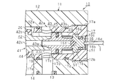
- (A) is sectional drawing which shows the balance poppet type solenoid valve of embodiment
- (b) is a side view which shows a valve seat formation body. Sectional drawing which shows the state which adjusted the position of the 2nd valve seat by the valve seat formation body. Sectional drawing which shows the state which sealed the communicating path with the manual shaft. Sectional drawing which shows the conventional solenoid valve.
- FIGS. 1A to 3 The right side of FIGS. 1A to 3 is defined as a first side, and the left side of FIGS. 1A to 3 is defined as a second side.
- the balance poppet electromagnetic valve 10 includes a valve unit 11 for switching a flow path of positive pressure air as a fluid, and a solenoid unit 31 for driving the valve unit 11. .
- the valve part 11 and the solenoid part 31 are integrated with each other by screwing.
- the valve unit 11 includes a body 12 formed in a cylindrical shape from a nonmagnetic material, for example, a synthetic resin material. Both ends of the body 12 are open.
- a direction extending along the central axis L of the body 12 is defined as an axial direction.
- a female screw 12b is formed on the first side of the body 12 in the axial direction.
- a first valve hole 12a that is continuous with the female screw 12b is formed.
- a second valve hole 12c having an inner diameter smaller than the inner diameter of the first valve hole 12a is formed on the second side in the axial direction of the body 12 so as to be continuous with the first valve hole 12a.
- a step is formed by the difference between the inner diameter of the first valve hole 12a and the inner diameter of the second valve hole 12c.
- a first valve seat 18 projects from the step so as to surround the second valve hole 12c.
- a support portion 12d is formed on the second side of the body 12 in the axial direction so as to protrude from the inner peripheral surface of the second valve hole 12c.
- an accommodation recess 12f having an inner diameter larger than the inner diameter of the second valve hole 12c is formed on the second side in the axial direction of the body 12 with respect to the support portion 12d.
- the body 12 is formed in a cylindrical shape penetrating over the entire axial direction by the female screw 12b, the first valve hole 12a, the second valve hole 12c, the support portion 12d, and the housing recess 12f.
- the body 12 has an axial first side opened by a female screw 12b, and an axial second side opened by an accommodation recess 12f.
- the body 12 is formed with a supply port 13, an output port 14, and a discharge port 15 forming a flow path in this order from the first end to the second end in the axial direction.
- the supply port 13 and the output port 14 are formed to communicate with the first valve hole 12 a in the body 12, and the discharge port 15 is formed to communicate with the second valve hole 12 c in the body 12. Yes.
- a positive pressure supply source (not shown) of positive pressure air is connected to the supply port 13, and a pneumatic device (not shown) such as an air cylinder is connected to the output port 14.
- the exhaust port 15 is connected to an exhaust pipe (not shown).
- the positive pressure air supplied to the supply port 13 is not output to the output port 14 or is output to the output port 14 by the switching operation of the balance poppet solenoid valve 10.
- the valve seat forming body 17 is screwed onto the female screw 12b of the body 12, and the opening at the first end of the body 12 is sealed by the valve seat forming body 17.
- the valve seat forming body 17 is formed in a cylindrical shape from a synthetic resin material.
- a male screw 17a is formed on the outer peripheral surface of the first side.
- the valve seat forming body 17 includes a cylindrical valve accommodating portion 17b on the second side from the male screw 17a.
- the maximum outer diameter of the valve accommodating portion 17b is set slightly smaller than the inner diameter of the first valve hole 12a.
- a first O-ring 17d is mounted in the vicinity of the male screw 17a on the outer peripheral surface of the valve housing portion 17b, and a second O-ring 17e is mounted on the distal end side of the valve housing portion 17b.
- a plurality of communication holes 17c are formed between the first O-ring 17d and the second O-ring 17e to communicate the inside and the outside of the valve housing portion 17b.
- a fitting hole 17 f is formed on the first side of the valve seat forming body 17 so as to open to the end surface on the first side of the valve seat forming body 17.
- the inner diameter of the fitting hole 17f is formed to be large at a portion corresponding to the valve accommodating portion 17b.
- a contact step 17 g is formed on the inner peripheral surface of the valve seat forming body 17.
- the manual shaft 16 is slidably fitted in the fitting hole 17f.
- the manual shaft 16 is formed of a flange portion 16a that can be brought into contact with the contact step 17g and a fitting portion 16b that is fitted into the fitting hole 17f.
- the fitting part 16b has an outer diameter smaller than the outer diameter of the flange part 16a. The contact of the flange portion 16a with the contact step 17g prevents the manual shaft 16 from coming off from the valve seat forming body 17.
- An O-ring 16c is mounted on the outer peripheral surface of the fitting portion 16b, and air leakage from the valve seat forming body 17 (inside the body 12) is prevented by the O-ring 16c.
- An operation recess 16d is formed on the end face of the fitting portion 16b.
- a sealing member 16f made of a rubber material is attached to the end face of the flange portion 16a.
- an end surface exposed to the valve accommodating portion 17b is curved in an arc shape and is formed to be elastically deformable.
- the manual shaft 16 having the above-described configuration is provided to be slidable along the axial direction of the valve seat forming body 17.
- valve seat forming body 17 In the valve seat forming body 17, the valve seat forming body 17 is inserted into the female screw 12 b of the body 12 in a state where the valve housing portion 17 b is inserted into the first valve hole 12 a, so that the valve seat forming body 17 is 12 and the opening on the first side of the body 12 is sealed.
- the supply port 13 and the inside of the valve accommodating portion 17b In a state where the valve seat forming body 17 is assembled to the body 12, the supply port 13 and the inside of the valve accommodating portion 17b (inside the first valve hole 12a) communicate with each other through the communication hole 17c.
- the second O-ring 17 e is in pressure contact with the inner peripheral surface of the body 12 located between the supply port 13 and the output port 14.
- the second O-ring 17e prevents the supply port 13 and the output port 14 from communicating with each other via a boundary between the outer peripheral surface of the valve seat forming body 17 and the inner peripheral surface of the body 12. Further, the positive pressure air supplied to the supply port 13 leaks to the outside of the body 12 through the boundary between the outer peripheral surface of the valve seat forming body 17 and the inner peripheral surface of the body 12 by the first O-ring 17d. It is prevented from coming out.
- the distal end surface of the valve accommodating portion 17b is disposed between the output port 14 and the supply port 13 in the axial direction of the body 12, and the second valve seat 19 is formed by the distal end surface of the valve accommodating portion 17b.
- the position of the second valve seat 19 can be adjusted along the axial direction of the body 12 by the amount of engagement of the male screw 17a with the female screw 12b.
- a valve chamber 20 is formed between the first valve seat 18 and the second valve seat 19 in the first valve hole 12a.
- a poppet valve 41 is accommodated in the body 12 and the valve seat forming body 17 so as to be movable in the axial direction of the body 12.
- the poppet valve 41 is formed of a first valve rod 42 and a second valve rod 43 integrated with the first valve rod 42.
- a first portion of the first valve rod 42 is accommodated in the valve accommodating portion 17b, and a second portion of the first valve rod 42 is inserted into the support portion 12d.
- the second valve rod 43 is accommodated in the valve accommodating portion 17 b of the valve seat forming body 17.
- the first valve rod 42 is formed of a shaft portion 42a and a valve body mounting portion 42b formed at the center in the longitudinal direction of the shaft portion 42a.
- the valve body attaching part 42b has an outer diameter larger than the outer diameter of the shaft part 42a.
- a valve body 44 is provided in the valve body mounting portion 42b.
- the outer diameter of the valve body 44 in the poppet valve 41 is larger than the second valve hole 12c and smaller than the first valve hole 12a.
- the valve body 44 is disposed so as to face the first valve seat 18 and the second valve seat 19. That is, the first valve seat 18 and the second valve seat 19 are disposed at positions that sandwich the valve body 44 in the axial direction of the body 12.
- the first valve rod 42 is formed with a first communication passage 42c that extends over the entire longitudinal direction of the shaft portion 42a.
- a communication groove 42 d for communicating the first communication passage 42 c and the outside of the first valve rod 42 is formed on the end surface of the first valve rod 42 opposite to the second valve rod 43.
- the second valve rod 43 is formed of a shaft portion 43a and a seal mounting portion 43b formed at the center portion in the longitudinal direction of the shaft portion 43a and having an outer diameter larger than the outer diameter of the shaft portion 43a.
- the outer diameter of the seal mounting portion 43b is set slightly smaller than the inner diameter of the valve housing portion 17b.
- a seal member 45 is attached to the outer peripheral surface of the seal attachment portion 43b. The seal member 45 is in sliding contact with the inner peripheral surface of the valve accommodating portion 17b when the poppet valve 41 moves in the body 12.
- the second valve rod 43 is formed with a second communication passage 43c extending over the entire longitudinal direction of the shaft portion 43a.
- the first communication passage 42c of the first valve rod 42 and the second communication passage 43c of the second valve rod 43 communicate with each other to form one communication passage.
- the opening located on the side opposite to the first valve rod 42 is formed in a tapered shape so that the diameter gradually increases from the second communication passage 43c toward the outside.
- a first pressure chamber S ⁇ b> 1 defined by the second valve rod 43 and the valve seat forming body 17 is provided at a position on the first side of the poppet valve 41.
- the 2nd communicating path 43c of the 2nd valve rod 43 is opened toward 1st pressure chamber S1.
- a valve spring 23 is interposed in the first pressure chamber S1.
- the poppet valve 41 is biased in the direction in which the valve body 44 is separated from the second valve seat 19 by the spring force of the valve spring 23, in other words, in the direction in which the valve body 44 is seated on the first valve seat 18.
- the manual shaft 16 is biased in a direction away from the poppet valve 41 by the spring force of the valve spring 23.
- a second pressure chamber S ⁇ b> 2 defined by the solenoid portion 31 and the housing recess 12 f is provided at a position on the second side of the poppet valve 41.
- the first pressure chamber S1 and the second pressure chamber S2 communicate with each other through the communication groove 42d, the first communication passage 42c, and the second communication passage 43c of the poppet valve 41, and have the same pressure.
- the solenoid portion 31 is fixed to the opposite side of the body 12 from the valve seat forming body 17 by screwing, and is integrated with the valve portion 12.
- the solenoid unit 31 includes a magnetic cover 32 formed in a cylindrical shape from a magnetic material.
- a female screw 32 a is formed on the inner peripheral surface of the magnetic cover 32 opposite to the body 12.
- a cylindrical bobbin 33 around which a plurality of coils 33a are wound is disposed inside the magnetic cover 32.
- a guide ring 34 is provided in the magnetic cover 32 at a position closer to the body 12 than the bobbin 33.
- a substantially cylindrical fixed iron core 37 is accommodated in the bobbin 33.
- a male screw 37 a is formed at the tip of the fixed iron core 37.
- the fixed iron core 37 is assembled to the magnetic cover 32 by screwing the male screw 37 a into the female screw 32 a of the magnetic cover 32.
- a movable iron core 35 is inserted into the guide ring 34 and the bobbin 33.
- the end surface on the first side close to the body 12 abuts on the end surface of the poppet valve 41 (first valve rod 42).
- the second side end face close to the fixed iron core 37 is disposed so as to face the fixed iron core 37.
- the first side portion of the movable iron core 35 extends so as to enter the housing recess 12 f of the body 12.
- a flange portion 35a protruding outward in the radial direction is formed.
- An iron core spring 36 is interposed between the guide ring 34 and the flange portion 35a.
- the movable iron core 35 is biased in a direction away from the fixed iron core 37 by the spring force of the iron core spring 36.
- the spring force of the iron core spring 36 is set larger than the spring force of the valve spring 23.
- the poppet valve 41 is in the direction in which the valve body 44 is seated on the second valve seat 19. Is being energized.
- the operation of the balance poppet solenoid valve 10 having the above-described configuration will be described.
- the difference in spring force between the iron core spring 36 and the valve spring 23 is obtained when the coil 33a of the solenoid 31 is not energized.
- the movable iron core 35 is biased toward the body 12 by (biasing force).
- the end surface on the first side of the movable iron core 35 is in contact with the support portion 12d.
- the poppet valve 41 is pressed into the body 12 by the movable iron core 35, and the valve body 44 is seated on the second valve seat 19.
- the pressure of the positive pressure air at the supply port 13 acts on the valve body 44 and the seal mounting portion 43b.
- the pressure receiving areas of the valve body 44 and the seal attachment portion 43b are set to the same size, the pressures acting on the valve body 44 and the seal attachment portion 43b are offset.
- the pressure (atmospheric pressure) at the output port 14 and the discharge port 15 passes between the support portion 12d and the shaft portion 42a of the first valve rod 42 through the second valve hole 12c, and the second pressure from the communication groove 42d. Acts on chamber S2.
- the pressure in the second pressure chamber S2 acts on the first pressure chamber S1 via the first communication passage 42c of the first valve rod 42 and the second communication passage 43c of the second valve rod 43, and the first pressure chamber S1. And the second pressure chamber S2 have the same pressure.
- the sealing member 45 ensures a sealing property between the first pressure chamber S1 and the supply port 13 (flow path), and prevents positive pressure air in the first pressure chamber S1 from leaking to the supply port 13. Therefore, the poppet valve 41 receives the same force simultaneously from both sides thereof and is maintained in an equilibrium state. Therefore, the poppet valve 41 is seated on the second valve seat 19 only by the difference in spring force between the iron core spring 36 and the valve spring 23. Further, the sealing property between the supply port 13 and the output port 14 is ensured, and the positive pressure air supplied to the supply port 13 is not output to the output port 14.
- the pressure of the positive pressure air in the supply port 13 acts on the valve body 44 and the seal mounting portion 43b. Since the pressure receiving areas of the valve body 44 and the seal attachment portion 43b are set to be the same, the pressure acting on the valve body 44 and the seal attachment portion 43b is canceled out.
- the pressure in the discharge port 15 passes between the support portion 12d and the shaft portion 42a of the first valve rod 42 through the second valve hole 12c, and acts on the second pressure chamber S2 through the communication groove 42d.
- the pressure in the second pressure chamber S2 acts on the first pressure chamber S1 via the first communication passage 42c of the first valve rod 42 and the second communication passage 43c of the second valve rod 43, and the first pressure chamber S1. And the second pressure chamber S2 have the same pressure.
- the sealing member 45 ensures a sealing property between the first pressure chamber S1 and the supply port 13, and prevents positive pressure air in the first pressure chamber S1 from leaking to the supply port 13. Therefore, the poppet valve 41 is seated on the first valve seat 18 only by the spring force of the valve spring 23, and the sealing performance between the output port 14 and the discharge port 15 is ensured.
- the poppet valve 41 is assembled by integrating the first valve rod 42, the second valve rod, and the valve body 44.
- the poppet valve 41 is inserted into the body 12 from the first valve rod 42.
- the poppet valve 41 is inserted into the body 12 from the first side of the body 12, that is, the opening formed by the female screw 12b.
- the poppet valve 41 is assembled to the body 12.
- the operator can perform the operation of assembling the poppet valve 41 while visually confirming the inside of the body 12.
- the second side portion of the poppet valve 41 is inserted into the second valve hole 12 c having an inner diameter larger than the outer diameter of the first valve rod 42. Further, the first side portion of the poppet valve 41 is inserted into the first valve hole 12 a and the female screw 12 b having an inner diameter larger than the outer diameter of the valve body 44 and the seal member 45. At this time, the seal member 45 is disposed on the side of the body 12 where the valve seat forming body 17 is assembled with the valve body 44 as a boundary. That is, the seal member 45 is disposed between the valve body 44 and the first end of the body 12 in the poppet valve 41.
- the seal mounting portion 43 b provided with the seal member 45 does not collide with the second valve seat 19. Further, the valve body 44 and the seal member 45 are prevented from coming into contact with the inner peripheral surface of the body 12.
- valve seat forming body 17 assembled with the manual shaft 16 is moved from the valve housing portion 17b to the body 12. Inserted inside. Then, the male screw 17 a of the valve seat forming body 17 is screwed to the female screw 12 b of the body 12. Then, the valve accommodating part 17b is arrange
- the flow rate output from the output port 14 is measured in a state where positive pressure air is supplied to the supply port 13.
- the second valve seat 19 is adjusted by adjusting the screwing amount of the valve seat forming body 17 to the female screw 12b of the body 12, as shown in FIG.
- the flow rate is adjusted by adjusting the position of.
- the operating current in the solenoid unit 31 is adjusted by adjusting the screwing amount of the fixed iron core 37 to the magnetic cover 32 in the solenoid unit 31.
- the flow rate output from the output port 14 may be measured by manually moving the poppet valve 41 without energizing the coil 33a.
- the tip of the tool T is inserted into the operation recess 16 d of the manual shaft 16, and the manual shaft 16 is pushed into the body 12 by the tool T.
- the poppet valve 41 is pressed, the valve body 44 is seated on the first valve seat 18, and the positive pressure air supplied to the supply port 13 can be output to the output port 14.
- the body 12 is formed in a cylindrical shape, and the valve seat forming body 17 is assembled to the first side portion of the body 12.
- a second valve seat 19 is provided in the body 12 by the valve seat forming body 17, and the opening on the first side of the body 12 is sealed by the valve seat forming body 17.
- the poppet valve 41 is assembled to the body 12 so that the seal member 45 for maintaining the equilibrium state of the poppet valve 41 is located on the side of the body 12 where the valve seat forming body 17 is assembled. That is, the seal member 45 is disposed between the valve body 44 of the poppet valve 41 and the first end of the body 12.
- the poppet valve 41 is assembled to the body 12, and then the valve seat forming body 17 is assembled to the body 12 so as to be located outside the seal member 45. Therefore, the part located on the second side of the poppet valve 41 is inserted and assembled into a hole having an inner diameter larger than the outer diameter of the seal member 45. Therefore, the seal member 45 is less likely to contact the inner peripheral surface of the body 12, and the seal attachment portion 43 b to which the seal member 45 is attached does not collide with the second valve seat 19. Therefore, when assembling the poppet valve 41 to the body 12, the assembly work is carefully performed in consideration of the contact of the seal member 45 with the second valve seat 19 and the contact of the seal member 45 with the inner peripheral surface of the body 12. There is no need to do it. As a result, the operation of assembling the poppet valve 41 to the body 12 can be easily performed, and as a result, the assemblability of the balance poppet solenoid valve 10 can be improved.
- the seal member 45 of the poppet valve 41 is not on the side of the body 12 where the solenoid part 31 is provided with the valve body 44 as a boundary, but on the opposite side of the solenoid part 31 with respect to the valve body 44, that is, from the solenoid part 31. It is provided so as to be positioned on a more separated side. For this reason, the seal member 45 can be arranged further away from such a solenoid part 31. Therefore, it is possible to make the seal member 45 less susceptible to temperature rise and wear powder, and the durability of the seal member 45 can be improved.
- a seal member 45 is disposed inside the valve housing portion 17b of the valve seat forming body 17, and the first side portion of the poppet valve 41 is slidably supported by the seal member 45. Therefore, the valve seat forming body 17 also has a function as a bearing for the poppet valve 41 in addition to the function for providing the second valve seat 19 on the body 12. Therefore, the balance poppet type solenoid valve is different from the case where the body 12 is provided with a part for providing the second valve seat 19 and the part for providing the function as a bearing for the poppet valve 41 separately. Ten configurations can be simplified.
- the valve seat forming body 17 is formed in a cylindrical shape from a synthetic resin material. For this reason, the roundness of the valve seat forming body 17 can be increased.
- the seal member 45 of the poppet valve 41 is in sliding contact with the inner peripheral surface of the valve seat forming body 17, but the roundness of the valve seat forming body 17 is increased, whereby the seal member 45.
- the slidability of the poppet valve 41 can be improved.
- the valve seat forming body 17 includes a male screw 17a, and is assembled to the body 12 by screwing the male screw 17a with the female screw 12b of the body 12. And the position of the 2nd valve seat 19 can be adjusted by adjusting the screwing amount of the external thread 17a. Therefore, the flow rate of the balance poppet type electromagnetic valve 10 can be easily adjusted.
- the fixed iron core 37 is provided with a male screw 37a.
- the male screw 37 a By fixing the male screw 37 a to the female screw 32 a of the magnetic cover 32, the fixed iron core 37 is assembled integrally with the magnetic cover 32. Then, by adjusting the screwing amount of the male screw 37a, the position of the fixed iron core 37 can be adjusted, and the stroke amount of the movable iron core 35 can be adjusted. Therefore, it is possible to easily adjust the operating current of the balance poppet solenoid valve 10. Therefore, from the effect described in the above (5), the balance poppet solenoid valve 10 is capable of adjusting the flow rate by adjusting the position of the second valve seat 19 by the valve seat forming body 17 and adjusting the operating current by adjusting the position of the fixed core 37. Two adjustments can be made.
- valve body 44 In the valve body 44, the contact portion with respect to the first valve seat 18 and the second valve seat 19 is formed in a flat surface shape. For this reason, when the valve body 44 is seated on the first valve seat 18 or the second valve seat 19, the space between the valve body 44 and the first valve seat 18 or the second valve seat 19 can be reliably sealed.
- the valve seat forming body 17 is provided with a manual shaft 16, and the poppet valve 41 can be manually moved by operating the manual shaft 16.
- the manual shaft 16 includes a sealing member 16 f that seals the second communication passage 43 c of the poppet valve 41 when the poppet valve 41 is moved by the manual shaft 16.
- the poppet valve 41 is pushed by being inclined with respect to the central axis L by the manual shaft 16, the sealing function by the sealing member 45 is lowered, and the positive pressure air from the supply port 13 leaks into the first pressure chamber S1.
- the end surface of the sealing member 16f provided on the manual shaft 16 is curved in an arc shape. For this reason, when the poppet valve 41 is pressed by the manual shaft 16, the sealing member 16f tends to come into close contact with the shape of the open end of the second communication passage 43c. Therefore, the opening of the second communication passage 43c can be reliably sealed by the sealing member 16f.
- valve seat forming body 17 formed in a cylindrical shape is assembled to the first side portion of the body 12.
- a second valve seat 19 is provided in the body 12 by the valve seat forming body 17.
- a seal member 45 for maintaining an equilibrium state of the poppet valve 41 is disposed on the body 12 on the side where the valve seat forming body 17 is assembled with the valve body 44 as a boundary.
- the seal member 45 moves integrally with the poppet valve 41 and slides on the inner peripheral surface of the valve seat forming body 17. For this reason, the crushing amount (projection amount) of the seal member 45 from the seal mounting portion 43b is set slightly.
- a high roundness is required for the valve seat forming body 17 in close contact with the seal member 45.
- the valve seat forming body 17 is formed in a cylindrical shape from a synthetic resin material, and high roundness can be easily realized. Therefore, the sealing member 45 can be brought into close contact with the inner peripheral surface of the valve seat forming body 17 over the entire circumference so that the sealing function can be sufficiently exerted. Therefore, in this embodiment, in order to maintain the equilibrium state of the poppet valve 41, it is not necessary to bring the seal member 45 into close contact with the inner peripheral surface of the body 12, and the body 12 can be manufactured from a synthetic resin.
- the valve body is made of metal and is a perfect circle in order to bring the seal member for maintaining the equilibrium state of the poppet valve into close contact with the valve hole over the entire circumference. A high degree valve hole is formed by cutting. Compared with the apparatus, in this embodiment, the manufacturing cost of the body 12 can be suppressed, and the manufacturing cost of the balance poppet type solenoid valve 10 can be reduced.
- the position of the seal member 45 may be arbitrarily changed at a position between the valve body 44 and the first side end of the poppet valve 41, that is, the tip.
- the contact part to the 1st valve seat 18 or the 2nd valve seat 19 in the valve body 44 does not need to be formed in flat surface shape.
- the fixed iron core 37 in the solenoid unit 31 may be integrated with the magnetic cover 32 so as not to move.
- the valve seat forming body 17 may be assembled to the body 12 by another means such as press fitting or fitting, instead of being screwed to the body 12.
- the valve seat forming body 17 may be assembled to the opening on the second side of the body 12, that is, the portion adjacent to the solenoid portion 31.
- the valve seat forming body 17 may be formed in a rectangular tube shape instead of the cylindrical shape.
- the valve seat forming body 17 is assembled to the body 12, and the body 12 and the solenoid unit 31 are integrated.
- the above assembling procedure may be changed as follows.
- the valve seat forming body 17 may be assembled to the body 12 after the poppet valve 41 is assembled to the body 12 in a state where the solenoid portion 31 is assembled to the body 12.
- valve part 11 and the solenoid part 31 are integrated by screwing.
- valve portion 11 and the solenoid portion 31 may be integrated by another means such as caulking, welding, or a fixing method using an elastic body.
Abstract
Description
前記弁座形成体は、前記ボディにおいて前記ソレノイド部とは反対側に組付けられていることが好ましい。
前記ソレノイド部は、磁気カバーに組付けられる固定鉄心を備え、前記固定鉄心は前記磁気カバーに対し位置調節可能に組付けられていることが好ましい。
前記弁座形成体には、前記ポペット弁を押圧して移動させる手動軸が設けられるとともに、前記手動軸には前記ポペット弁の押圧時に前記連通路を封止する封止部材が設けられていることが好ましい。
ソレノイド部31は、ボディ12における弁座形成体17とは反対側に螺子止めにより固定されており、弁部12と一体化されている。ソレノイド部31は、磁性材料により筒状に形成された磁気カバー32を備える。磁気カバー32においてボディ12と反対側の内周面には、雌ねじ32aが形成されている。磁気カバー32の内側には、コイル33aが複数巻回された筒状のボビン33が配設されている。また、磁気カバー32の内部であって、ボビン33よりもボディ12に近い位置には、ガイドリング34が設けられている。
さて、図1(a)の拡大図における2点鎖線に示すように、ソレノイド部31のコイル33aへの通電が行われない状態では、鉄心用ばね36と弁用ばね23とのばね力の差(付勢力)により可動鉄心35がボディ12へ向かって付勢されている。可動鉄心35の第1側の端面が支持部12dに当接している。可動鉄心35によりポペット弁41がボディ12内に押圧され、弁体44が第2弁座19に着座している。
まず、第1弁棒42、第2弁棒、及び弁体44を一体化することによりポペット弁41が組み立てられる。ポペット弁41は、第1弁棒42から、ボディ12内に挿入される。詳しくは、ポペット弁41は、ボディ12の第1側、即ち雌ねじ12bによって形成される開口からボディ12内へ挿入される。このように、ボディ12にポペット弁41が組付けられる。このとき、弁座形成体17がボディ12にまだ組み付けられていないため、作業者は、ボディ12内を視認しながらポペット弁41を組付ける作業を行うことができる。そして、ポペット弁41の第2側の部分が、第1弁棒42の外径より大きい内径を有する第2弁孔12c内に挿入される。また、ポペット弁41の第1側の部分が、弁体44及びシール部材45の外径より大きい内径を有する第1弁孔12a及び雌ねじ12b内に挿入される。このとき、シール部材45は、ボディ12における弁体44を境に弁座形成体17の組み付けられる側に配設されている。即ち、シール部材45は、ポペット弁41において弁体44とボディ12の第1端との間に配設されている。このため、ポペット弁41をボディ12内に挿入する際、シール部材45の設けられたシール取付部43bが第2弁座19に衝突することが無くなる。また、弁体44及びシール部材45がボディ12の内周面に接触したりすることが防止される。
(1)ボディ12が筒状に形成され、ボディ12の第1側の部分に弁座形成体17が組み付けられている。弁座形成体17によりボディ12内に第2弁座19が設けられるとともに、その弁座形成体17によりボディ12の第1側の開口が封止されている。また、ポペット弁41の平衡状態を維持するためのシール部材45が、ボディ12において弁座形成体17の組み付けられた側に位置するように、ポペット弁41がボディ12に組付けられている。即ち、シール部材45は、ポペット弁41の弁体44とボディ12の第1端との間に配設されている。そして、バランスポペット式電磁弁10を組立てる際、ボディ12にポペット弁41を組付けた後に、弁座形成体17がシール部材45の外側に位置するようにボディ12に組み付けられる。よって、ポペット弁41の第2側に位置する部位は、シール部材45の外径より大きい内径を有する孔に挿入されて組付けられる。そのため、シール部材45がボディ12の内周面に接触しにくくなるとともに、シール部材45の装着されたシール取付部43bが第2弁座19に衝突することが無くなる。よって、ポペット弁41をボディ12に組付ける際、シール部材45の第2弁座19への接触や、シール部材45のボディ12の内周面への接触を意識して慎重に組付け作業を行う必要がない。その結果として、ポペット弁41をボディ12に組み付ける作業を簡単に行うことができ、結果としてバランスポペット式電磁弁10の組立性を向上させることができる。
○ シール部材45の位置は、弁体44とポペット弁41の第1側の端部、即ち先端との間の位置で任意に変更されてもよい。
○ ソレノイド部31における固定鉄心37は磁気カバー32に対し移動不能に一体化されていてもよい。
○ 弁座形成体17は、ボディ12における第2側の開口部、すなわちソレノイド部31と隣接する部分に組み付けられていてもよい。
○ 上記実施形態では、ボディ12にポペット弁41を収容した後、ボディ12に弁座形成体17が組付けられて、ボディ12とソレノイド部31とが一体化されている。これに代えて、上記組み付け手順は以下のように変更されてもよい。すなわり、ボディ12にソレノイド部31が組付けられた状態で、ボディ12にポペット弁41を組付けた後、ボディ12に弁座形成体17が組付けられてもよい。
Claims (8)
- 流体用の流路を有する弁部と同弁部に接続されたソレノイド部とを含むバランスポペット式電磁弁であって、
前記弁部は、
第1及び第2端を有し、前記第1及び第2端にそれぞれ第1及び第2開口を有するとともに、中心軸線を有する筒状のボディと、
前記ボディ内に区画された第1圧力室及び第2圧力室と、
前記ボディの軸方向に沿って移動可能に前記ボディ内に収容されるとともに、弁体を有するポペット弁と、
前記ポペット弁に形成され、前記第1圧力室と第2圧力室とを互いに連通する連通路と、
前記ボディの前記軸方向において前記弁体の両側に配設された一対の弁座とを備え、
前記ポペット弁が前記弁座に対し接触又は離間することにより前記流路を切り換え可能であるバランスポペット式電磁弁において、
前記ボディに組付けられ、前記ボディの前記第1端に位置する前記第1開口を封止するとともに、前記一対の弁座のうちの一方の弁座が形成される弁座形成体と、
前記ポペット弁に設けられ、前記第1圧力室と前記流路との間をシールするシール部材とを備え、前記シール部材が前記弁体と前記ボディの前記第1端との間に配設されているバランスポペット式電磁弁。 - 前記弁座形成体は筒状をなし、前記シール部材は、前記弁座形成体の内側に配設されるとともに、前記ポペット弁は、前記シール部材を介して前記弁座形成体に摺動可能に支持されている請求項1に記載のバランスポペット式電磁弁。
- 前記弁座形成体は合成樹脂材料により円筒状に形成されている請求項1又は請求項2に記載のバランスポペット式電磁弁。
- 前記弁座形成体は、前記ボディにおいて前記ソレノイド部とは反対側の部位に組付けられている請求項1又は請求項2に記載のバランスポペット式電磁弁。
- 前記弁座形成体は前記ボディに対し螺合により組付けられている請求項1又は請求項2に記載のバランスポペット式電磁弁。
- 前記ソレノイド部は、磁気カバーと同磁気カバーに組付けられる固定鉄心とを備え、前記固定鉄心は前記磁気カバーに対し位置調節可能に組付けられている請求項1又は請求項2に記載のバランスポペット式電磁弁。
- 前記弁体は前記弁座と接触する接触部を有し、前記接触部は平坦面状に形成されている請求項1又は請求項2に記載のバランスポペット式電磁弁。
- 前記弁座形成体には、前記ポペット弁を押圧して移動させる手動軸が設けられるとともに、前記手動軸には前記ポペット弁の押圧時に前記連通路を封止する封止部材が設けられている請求項1又は請求項2に記載のバランスポペット式電磁弁。
Priority Applications (2)
| Application Number | Priority Date | Filing Date | Title |
|---|---|---|---|
| CN201180018135.5A CN102834656B (zh) | 2010-03-31 | 2011-02-17 | 平衡提升型电磁阀 |
| KR1020127023019A KR101429577B1 (ko) | 2010-03-31 | 2011-02-17 | 밸런스 포핏식 전자 밸브 |
Applications Claiming Priority (2)
| Application Number | Priority Date | Filing Date | Title |
|---|---|---|---|
| JP2010-081273 | 2010-03-31 | ||
| JP2010081273A JP5486987B2 (ja) | 2010-03-31 | 2010-03-31 | バランスポペット式電磁弁 |
Publications (1)
| Publication Number | Publication Date |
|---|---|
| WO2011122147A1 true WO2011122147A1 (ja) | 2011-10-06 |
Family
ID=44711882
Family Applications (1)
| Application Number | Title | Priority Date | Filing Date |
|---|---|---|---|
| PCT/JP2011/053369 WO2011122147A1 (ja) | 2010-03-31 | 2011-02-17 | バランスポペット式電磁弁 |
Country Status (4)
| Country | Link |
|---|---|
| JP (1) | JP5486987B2 (ja) |
| KR (1) | KR101429577B1 (ja) |
| CN (1) | CN102834656B (ja) |
| WO (1) | WO2011122147A1 (ja) |
Cited By (1)
| Publication number | Priority date | Publication date | Assignee | Title |
|---|---|---|---|---|
| EP3667140A1 (en) * | 2018-12-14 | 2020-06-17 | Marotta Controls, Inc. | Solenoid valve |
Families Citing this family (12)
| Publication number | Priority date | Publication date | Assignee | Title |
|---|---|---|---|---|
| JP5903845B2 (ja) * | 2011-11-22 | 2016-04-13 | アイシン精機株式会社 | 電磁弁 |
| JP2014026049A (ja) | 2012-07-25 | 2014-02-06 | Sony Corp | クリーニング装置とクリーニング方法および撮像装置 |
| JP5938378B2 (ja) * | 2013-09-18 | 2016-06-22 | Ckd株式会社 | 電磁弁 |
| JP6531126B2 (ja) * | 2016-03-01 | 2019-06-12 | Ckd株式会社 | 電磁弁 |
| JP6698251B2 (ja) * | 2016-05-19 | 2020-05-27 | Smc株式会社 | 電磁弁 |
| JP6732202B2 (ja) * | 2016-05-19 | 2020-07-29 | Smc株式会社 | 電磁弁 |
| JP6507140B2 (ja) * | 2016-11-08 | 2019-04-24 | Ckd株式会社 | 電磁弁 |
| KR101987455B1 (ko) * | 2018-01-26 | 2019-09-30 | (주)모토닉 | 전자식 솔레노이드 밸브의 조립 구조 |
| KR101987456B1 (ko) * | 2018-01-26 | 2019-06-12 | (주)모토닉 | 전자식 솔레노이드 밸브의 슬리브 구조 |
| JP2019219006A (ja) * | 2018-06-20 | 2019-12-26 | アズビルTaco株式会社 | 電磁弁 |
| CN111765252B (zh) * | 2019-04-02 | 2021-12-21 | 浙江三花制冷集团有限公司 | 一种电动阀 |
| KR102473837B1 (ko) * | 2021-04-22 | 2022-12-02 | 박석배 | 엔진 시동용 3웨이 밸브 |
Citations (4)
| Publication number | Priority date | Publication date | Assignee | Title |
|---|---|---|---|---|
| JPH0466472U (ja) * | 1990-10-20 | 1992-06-11 | ||
| JPH0636371Y2 (ja) * | 1988-03-14 | 1994-09-21 | シーケーディ株式会社 | 電磁弁 |
| JP2000018400A (ja) * | 1998-07-02 | 2000-01-18 | Smc Corp | ポペット弁 |
| JP2006046414A (ja) * | 2004-08-02 | 2006-02-16 | Smc Corp | 3ポート電磁弁 |
Family Cites Families (8)
| Publication number | Priority date | Publication date | Assignee | Title |
|---|---|---|---|---|
| JPS6196272A (ja) * | 1984-10-13 | 1986-05-14 | Kuroda Precision Ind Ltd | 方向切換弁 |
| US6129115A (en) * | 1999-07-02 | 2000-10-10 | Mac Valves, Inc. | Self-latching solenoid valve assembly |
| JP3590765B2 (ja) * | 2000-12-21 | 2004-11-17 | Smc株式会社 | 電磁弁 |
| JP3994871B2 (ja) * | 2002-12-19 | 2007-10-24 | いすゞ自動車株式会社 | 圧力比例制御弁 |
| CN2773416Y (zh) * | 2005-01-17 | 2006-04-19 | 哈尔滨志阳汽车电气股份有限公司 | 碳罐电磁阀 |
| JP2006258183A (ja) * | 2005-03-16 | 2006-09-28 | Kuroda Pneumatics Ltd | ポペット式方向制御弁 |
| US8151824B2 (en) * | 2007-04-05 | 2012-04-10 | Mac Valves, Inc. | Balanced solenoid valve |
| JP5249191B2 (ja) * | 2009-12-25 | 2013-07-31 | Ckd株式会社 | 電磁弁 |
-
2010
- 2010-03-31 JP JP2010081273A patent/JP5486987B2/ja active Active
-
2011
- 2011-02-17 KR KR1020127023019A patent/KR101429577B1/ko active IP Right Grant
- 2011-02-17 WO PCT/JP2011/053369 patent/WO2011122147A1/ja active Application Filing
- 2011-02-17 CN CN201180018135.5A patent/CN102834656B/zh active Active
Patent Citations (4)
| Publication number | Priority date | Publication date | Assignee | Title |
|---|---|---|---|---|
| JPH0636371Y2 (ja) * | 1988-03-14 | 1994-09-21 | シーケーディ株式会社 | 電磁弁 |
| JPH0466472U (ja) * | 1990-10-20 | 1992-06-11 | ||
| JP2000018400A (ja) * | 1998-07-02 | 2000-01-18 | Smc Corp | ポペット弁 |
| JP2006046414A (ja) * | 2004-08-02 | 2006-02-16 | Smc Corp | 3ポート電磁弁 |
Cited By (2)
| Publication number | Priority date | Publication date | Assignee | Title |
|---|---|---|---|---|
| EP3667140A1 (en) * | 2018-12-14 | 2020-06-17 | Marotta Controls, Inc. | Solenoid valve |
| US11022231B2 (en) | 2018-12-14 | 2021-06-01 | Marotta Controls, Inc. | Solenoid valve |
Also Published As
| Publication number | Publication date |
|---|---|
| JP5486987B2 (ja) | 2014-05-07 |
| CN102834656B (zh) | 2014-03-12 |
| JP2011214612A (ja) | 2011-10-27 |
| KR20120112858A (ko) | 2012-10-11 |
| CN102834656A (zh) | 2012-12-19 |
| KR101429577B1 (ko) | 2014-08-12 |
Similar Documents
| Publication | Publication Date | Title |
|---|---|---|
| WO2011122147A1 (ja) | バランスポペット式電磁弁 | |
| KR101723128B1 (ko) | 밸브 부재 단부를 밀봉하기 위한 다이어프램을 구비한 압력 평형 밸브 | |
| CA2908256C (en) | Valve device | |
| KR101274735B1 (ko) | 압력 보정 방법 | |
| TWI683071B (zh) | 隔膜閥 | |
| JP2010065780A (ja) | 電磁開閉弁 | |
| KR20150034103A (ko) | 전자 밸브 | |
| EP1564467A1 (en) | Electromagnetic valve | |
| US7562675B2 (en) | Valve device | |
| US6752375B2 (en) | Solenoid-operated valve | |
| JP4492649B2 (ja) | ブリード式バルブ装置 | |
| JP5292231B2 (ja) | 制御弁 | |
| JP4703615B2 (ja) | ブリード式バルブ装置 | |
| JP2008267474A (ja) | ブリード式バルブ装置 | |
| JP5712092B2 (ja) | パイロット機能付き弁 | |
| US20240093790A1 (en) | Pilot valve having diaphragm | |
| JP5722164B2 (ja) | 減圧装置 | |
| WO2021137174A1 (en) | Oil control solenoid valve with dual sealing | |
| CN117098943A (zh) | 阀 | |
| NZ741227A (en) | Diaphragm Valve |
Legal Events
| Date | Code | Title | Description |
|---|---|---|---|
| WWE | Wipo information: entry into national phase |
Ref document number: 201180018135.5 Country of ref document: CN |
|
| 121 | Ep: the epo has been informed by wipo that ep was designated in this application |
Ref document number: 11762388 Country of ref document: EP Kind code of ref document: A1 |
|
| ENP | Entry into the national phase |
Ref document number: 20127023019 Country of ref document: KR Kind code of ref document: A |
|
| NENP | Non-entry into the national phase |
Ref country code: DE |
|
| 122 | Ep: pct application non-entry in european phase |
Ref document number: 11762388 Country of ref document: EP Kind code of ref document: A1 |