WO2011122124A1 - 血圧測定装置 - Google Patents
血圧測定装置 Download PDFInfo
- Publication number
- WO2011122124A1 WO2011122124A1 PCT/JP2011/052763 JP2011052763W WO2011122124A1 WO 2011122124 A1 WO2011122124 A1 WO 2011122124A1 JP 2011052763 W JP2011052763 W JP 2011052763W WO 2011122124 A1 WO2011122124 A1 WO 2011122124A1
- Authority
- WO
- WIPO (PCT)
- Prior art keywords
- cuff
- blood pressure
- fluid
- bag
- winding
- Prior art date
- Legal status (The legal status is an assumption and is not a legal conclusion. Google has not performed a legal analysis and makes no representation as to the accuracy of the status listed.)
- Ceased
Links
Images






Classifications
-
- A—HUMAN NECESSITIES
- A61—MEDICAL OR VETERINARY SCIENCE; HYGIENE
- A61B—DIAGNOSIS; SURGERY; IDENTIFICATION
- A61B5/00—Measuring for diagnostic purposes; Identification of persons
- A61B5/02—Detecting, measuring or recording for evaluating the cardiovascular system, e.g. pulse, heart rate, blood pressure or blood flow
- A61B5/021—Measuring pressure in heart or blood vessels
- A61B5/022—Measuring pressure in heart or blood vessels by applying pressure to close blood vessels, e.g. against the skin; Ophthalmodynamometers
- A61B5/02233—Occluders specially adapted therefor
-
- A—HUMAN NECESSITIES
- A61—MEDICAL OR VETERINARY SCIENCE; HYGIENE
- A61B—DIAGNOSIS; SURGERY; IDENTIFICATION
- A61B5/00—Measuring for diagnostic purposes; Identification of persons
- A61B5/02—Detecting, measuring or recording for evaluating the cardiovascular system, e.g. pulse, heart rate, blood pressure or blood flow
- A61B5/021—Measuring pressure in heart or blood vessels
- A61B5/022—Measuring pressure in heart or blood vessels by applying pressure to close blood vessels, e.g. against the skin; Ophthalmodynamometers
- A61B5/0225—Measuring pressure in heart or blood vessels by applying pressure to close blood vessels, e.g. against the skin; Ophthalmodynamometers the pressure being controlled by electric signals, e.g. derived from Korotkoff sounds
Definitions
- the present invention relates to a blood pressure measuring device, and more particularly to a blood pressure measuring device that wraps and compresses a cuff around a measurement site during blood pressure measurement.
- Blood pressure is one of the indices for analyzing cardiovascular diseases, and risk analysis based on blood pressure is effective in preventing cardiovascular diseases such as stroke, heart failure and myocardial infarction.
- diagnosis has been performed based on blood pressure measured at a medical institution such as when visiting a hospital or during a medical examination.
- blood pressure measured at home is more useful for diagnosing cardiovascular diseases than blood pressure measured at medical institutions.
- blood pressure monitors used at home have become widespread, and more than 30 million units exist in each home in Japan.
- Blood pressure measurement by the oscillometric method is performed by wrapping a cuff around a measurement site such as the upper arm, and pressurizing the cuff internal pressure (cuff pressure) by a predetermined pressure (for example, 30 mmHg) higher than the systolic blood pressure, and then gradually or stepwise
- the cuff pressure is reduced, and the arterial volume change in the decompression process is detected as a pressure change (pressure pulse wave amplitude) superimposed on the cuff pressure, and the systolic blood pressure and the diastolic blood pressure are detected from the change in the pressure pulse wave amplitude. It is a method of determination.
- the oscillometric method it is also possible to measure the blood pressure by detecting the pressure pulse wave amplitude generated during the pressurization of the cuff pressure.
- a cuff is wound around a measurement site such as the upper arm in the same manner as the oscillometric method, and the cuff pressure is increased by a predetermined pressure from the systolic blood pressure.
- Korotkoff sound generated from the artery in the process of gradually reducing the cuff pressure is detected by a microphone provided in the cuff, and the cuff pressure at which Korotkoff sound was generated is detected as systolic blood pressure, and the cuff with Korotkoff sound attenuated or disappeared.
- This is a method for determining the pressure as a diastolic blood pressure.
- Patent Document 4 Japanese Patent Application Laid-Open No. 2007-275483 discloses a member for positioning the air bag in the cuff with respect to the upper arm as a technique for supporting correct attachment of the cuff to the measurement site. A technique to prepare for is disclosed.
- JP 2005-305028 A Japanese Patent Laid-Open No. 02-114934 JP 2008-188197 A JP 2007-275483 A
- the cuff winding strength is determined in the process in which the cuff is wound around the attachment site and the cuff pressure is increased, that is, at the start of blood pressure measurement. Done. Therefore, the winding strength cannot be determined before the blood pressure measurement is started, that is, before the cuff winding is completed in the measurement subject. For this reason, if it is determined in the above determination that the cuff winding strength is inappropriate, the measurement must be stopped, the cuff wound again, and then remeasured.
- the present invention has been conceived in view of the actual situation, and an object of the present invention is to make a blood pressure measurement device recognize whether or not a cuff can be accurately worn by a person to be measured before blood pressure measurement. .
- the blood pressure measurement device is a blood pressure measurement device including a cuff that compresses a measurement site by being wound, and includes an exterior part that covers an outline of the cuff, and a first fluid provided in the exterior part
- the bag and the cuff are provided with an indicating member provided to come into contact with the exterior portion and the first fluid bag, and the indicating member corresponds to the magnitude of the force pressed from the exterior portion and the first fluid bag.
- the characteristic changes to be visible.
- the indicating member includes a second fluid bag in which a plurality of fluids having different volume change amounts are sealed when pressed by a constant force.
- the indicating member includes a display unit that displays a change in characteristics, and the display unit is provided with an indicator that indicates the magnitude of the force with which the second fluid bag is pressed from the exterior unit and the first fluid bag.
- the indicator is a graphic described on the display unit and having a center at a position different from the center of the display unit.
- a plurality of indicating members are provided, and the plurality of indicating members are arranged in a direction crossing the winding direction in the cuff measurement site.
- a plurality of indicating members are provided, and the plurality of indicating members are arranged along the winding direction at the cuff measurement site.
- an indicator indicating the magnitude of the force with which the indicating member is pressed from the exterior part and the first fluid bag is further provided.
- the measurement subject can visually recognize the winding strength of the cuff by visually recognizing the change in the characteristics of the indicating member when the cuff is worn. Thereby, the person to be measured can recognize whether or not the cuff can be accurately worn before blood pressure measurement.
- FIG. 4 is a cross-sectional view of the cuff taken along line IV-IV shown in FIG. 3. It is a figure which shows the state which wound and fixed the cuff of the blood pressure meter of FIG. 1 around the measurement site
- FIG. 1 is a perspective view showing an external appearance of a sphygmomanometer that is one embodiment of the blood pressure measurement device of the present invention.
- blood pressure monitor 100 mainly includes apparatus body 110 and cuff 150.
- the apparatus main body 110 includes a display unit 114 and an operation unit 115.
- the display unit 114 displays the measurement result of the blood pressure value, the measurement result of the pulse rate, and the like so as to be visible using numerical values, graphs, and the like.
- a liquid crystal panel or the like is used as this display unit 114.
- the operation unit 115 is provided with a power button, a measurement start button, and the like, for example.
- the cuff 150 is intended to be wound around the measurement site of the measurement subject and has a belt-like outer shape.
- the cuff 150 includes an air bag 151 (see FIGS. 2 to 4) as a fluid bag for compressing the measurement site, and a bag-like cover as an exterior for winding and fixing the air bag 151 around the measurement site. And a body 161.
- the air bag 151 is accommodated in a space provided inside the bag-shaped cover body 161.
- the cuff 150 and the apparatus main body 110 are connected by an air pipe 140 as a connection pipe.
- the air tube 140 is made of a flexible tube, one end of which is connected to a blood pressure measurement air system component 131 (see FIG. 2) provided in the apparatus main body 110 to be described later, and the other end is the air of the cuff 150 described above. It is connected to the bag 151.
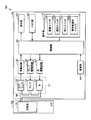
- FIG. 2 is a functional block diagram showing the configuration of the sphygmomanometer 100.
- blood pressure measurement air system component 131 for supplying or discharging air to / from air bag 151 contained in cuff 150 through air tube 140 is provided inside apparatus main body 110 of sphygmomanometer 100. Is provided.
- the blood pressure measurement air system component 131 includes a pressure sensor 132 that detects the pressure in the air bladder 151, a pump 134 and a valve 135 for inflating and contracting the air bladder 151.
- an oscillation circuit 125, a pump drive circuit 126, and a valve drive circuit 127 are provided inside the apparatus main body 110 in association with the blood pressure measurement air system component 131.
- the apparatus main body 110 includes a control unit 122 for centrally controlling and monitoring each unit, and a memory for storing various information such as a program for causing the control unit 122 to perform a predetermined operation and a measured blood pressure value.
- a power supply unit 124 for supply is installed.
- the control unit 122 also functions as blood pressure value calculation means for calculating the blood pressure value.
- the control unit 122 includes a CPU (Central Processing Unit).
- the pressure sensor 132 detects the pressure in the air bladder 151 (hereinafter, appropriately referred to as “cuff pressure”), and outputs a signal corresponding to the detected pressure to the oscillation circuit 125.
- the pump 134 supplies air to the air bladder 151.
- the valve 135 opens and closes when maintaining the pressure in the air bag 151 or exhausting the air in the air bag 151.
- the oscillation circuit 125 outputs a signal having an oscillation frequency corresponding to the output value of the pressure sensor 132 to the control unit 122.
- the pump drive circuit 126 controls the drive of the pump 134 based on a control signal given from the control unit 122.
- the valve drive circuit 127 controls opening and closing of the valve 135 based on a control signal given from the control unit 122.
- the operation unit 115 includes a power switch 115A that switches on / off the power supply to the sphygmomanometer 100, a measurement switch 115B that is operated when the sphygmomanometer 100 starts blood pressure measurement, and a blood pressure measurement operation that is being performed.
- a stop switch 115C operated to stop the user, and a user selection switch 115D for selecting a person to be measured of the sphygmomanometer 100.
- the memory unit 123 stores blood pressure values and pulse rate measurement results for each person to be measured.
- the stored measurement results are displayed on the display unit 114 so as to be visible using numerical values or graphs.
- the measurement result of the blood pressure value and the pulse rate stored in the memory unit 123 is displayed for each person to be measured by operating the user selection switch 115D.
- the memory unit 123 is configured by a storage medium.
- Storage media include CD-ROM (Compact Disc-Read Only Memory), DVD-ROM (Digital Versatile Disk-Read Only Memory), USB (Universal Serial Bus) memory, memory card, FD (Flexible Disk), hard disk, magnetic Tape, cassette tape, MO (Magnetic Optical Disc), MD (Mini Disc), IC (Integrated Circuit) card (excluding memory card), optical card, mask ROM, EPROM, EEPROM (Electronically Erasable Programmable Read-Only Memory), etc. And a medium for storing the program in a nonvolatile manner.
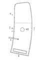
- FIG. 3 is a view showing a state where the cuff 150 of the sphygmomanometer 100 is unfolded
- FIG. 4 is a cross-sectional view of the cuff 150 taken along the line IV-IV shown in FIG.
- the cuff 150 has an air bag 151 connected to the air tube 140 and a bag-like cover body 161 that encloses the air bag 151.
- the air bag 151 has a substantially rectangular outer shape
- the bag-like cover body 161 has a substantially rectangular belt-like outer shape that encloses the air bag 151. have.
- the cuff 150 will surround and cover the measurement site in a state of being wound around the measurement site (for example, the upper arm).
- a hook-and-loop fastener 164 is provided on the outer peripheral surface near the end of the bag-shaped cover body 161. The surface fastener 164 is locked at a predetermined position on the outer peripheral surface of the bag-like cover body 161 in a state where the cuff 150 is attached to the upper arm.
- the winding strength instruction part 200 is fitted in the bag-shaped cover body 161.
- the winding strength instruction unit 200 includes a window 210 and a fluid bag 201 attached to the window 210.
- a plurality of fluids (fluid 221 and fluid 222) are enclosed in a space formed by the window 210 and the fluid bag 201.
- the fluid bag 201 is made of a material whose shape easily deforms when pressed from the outside, such as a sheet-like synthetic resin.
- the window 210 is made of a transparent material such as a transparent plastic so that the state in the fluid bag 201 can be visually recognized from the outside.
- the window 210 is embedded in the surface of the bag-shaped cover body 161, and the fluid bag 201 is stored in the bag-shaped cover body 161.
- the fluid bag 201 is disposed between the bag-like cover body 161 and the air bag 151 so as to abut against them.
- the air bag 151 constitutes a first fluid bag
- the fluid bag 201 constitutes a second fluid bag.
- the fluid enclosed with the 1st fluid bag is a fluid, it will not be limited to air like specific gas etc.
- the fluid 221 and the fluid 222 are fluids that do not mix with each other, and are fluids having different compressibility.
- one of the two types of fluid may be a liquid such as water, and the other fluid (fluid 222) may be a gas such as air.
- the cuff 150 is provided with the indicator member (winding strength indicator 200) provided so as to penetrate the exterior portion (bag-like cover body 161) that covers the outer shell of the cuff 150.
- the sealed fluid 221 and fluid 222 can be visually recognized from the outside of the cuff 150 through the window 210.
- the fluid bag 201 is made of a material that can be deformed by being pressed from the outside. Further, when a certain force is applied from the outside of the fluid bag 201, the volume of both (or either) of the fluid 221 and the fluid 222 changes. By visually recognizing such a change in volume through the window 210, the measurement subject can recognize how much force is applied to the fluid bag 201.
- the window 210 constitutes a display unit provided on the indicating member (winding strength indicating unit 200).
- the fluid bag 201 is sandwiched between the air bag 151 and the bag-like cover body 161 and pressed by them. And the force added to the fluid bag 201 by the air bag 151 and the bag-shaped cover body 161 becomes large because the intensity
- the force applied to the fluid bag 201 changes, the volume (at least one) of the fluid 221 and the fluid 222 in the fluid bag 201 changes.
- the wrapping strength of the cuff 150 around the measurement site can be increased by visually confirming the change in volume of the fluid 221 and the fluid 222 (or either one) in the fluid bag 201 through the window 210. Can be guessed.
- the plurality of fluids (fluid 221 and fluid 222) enclosed in the fluid bag 201 have different volumes that change when pressed with a constant force from the outside.
- the volume ratio of the fluid 221 and the fluid 222 in the fluid bag 201 is changed by changing the force applied to the fluid bag 201.
- the measurement subject can estimate the magnitude of the force applied to the fluid bag 201, that is, the winding strength of the cuff 150 around the measurement site.
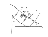
- FIG. 5 shows a state in which the cuff 150 of the sphygmomanometer 100 is wound around and fixed to the upper arm portion of the measurement subject's arm A (left arm), which is an example of a state in which the cuff 150 is wound and fixed around the measurement site.
- an arrow FR indicates a direction from the front of the person to be measured toward the person to be measured.
- the cuff 150 of the sphygmomanometer 100 is intended to be attached to the measurement site so that the winding strength instruction unit 200 is located on the right side of the front, that is, on the inside of the body from the front. ing.
- FIG. 6 shows a cross-sectional structure of the cuff 150 in the state shown in FIG.
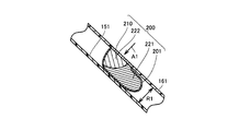
- winding strength instruction unit 200 has window 210 fixed to bag-shaped cover body 161 and is housed in bag-shaped cover body 161.
- the fluid bag 201 has its portion fixed to the window 210 as its upper end and its own weight. It is in a state of hanging from the window 210.
- the fluid 222 is located above the fluid 221 inside the fluid bag 201.
- FIG. 7 shows a state where the inside of the winding strength instruction unit 200 is viewed from the direction of the arrow A1 through the window 210 when the fluid bag 201 is in the state shown in FIG.
- the boundary between the fluid 221 and the fluid 222 is represented by a boundary line 290 inside the window 210.
- an indicator 211 indicates the position of the boundary line between the fluid 221 and the fluid 222 when the cuff 150 is wound around the measurement site with appropriate strength.
- the indicator 211 is attached in advance to the surface of the window 210 by printing or the like.
- FIG. 8 shows a cross-sectional view of the vicinity of the window 210 of the winding strength instruction section 200 when the winding strength is increased from the state shown in FIG.
- R1 in FIG. 6 and R2 in FIG. 8 indicate the distance between the air bag 151 and the bag-shaped cover body 161 inside the bag-shaped cover body 161, respectively.
- the relationship is R1> R2. That is, in the state shown in FIG. 8, the distance between the air bag 151 and the bag-like cover body 161 is shorter in the bag-like cover body 161 than in the state shown in FIG. 6. This is based on the fact that the force exerted on the bag-like cover body 161 from the measurement site is increasing. That is, in the state illustrated in FIG. 8, the fluid bag 201 is crushed with a greater force by the bag-shaped cover body 161 and the air bag 151 than in the state illustrated in FIG. 6.
- the fluid 221 and the fluid 222 are compressed.
- the volume ratio of the fluid 221 and the fluid 222 in the fluid bag 201 changes. Specifically, the fluid 222 is compressed at a greater rate than the fluid 221, so that in the state shown in FIG. 8, the volume of the fluid 222 in the entire fluid bag 201 is greater than in the state shown in FIG. 6. The proportion occupied by is getting smaller.
- FIG. 9 shows a state where the inside of the fluid bag 201 is viewed from the direction of the arrow A1 through the window 210 in the state shown in FIG.
- boundary line 290A the boundary between the fluid 221 and the fluid 222 is indicated by a boundary line 290A.
- the boundary line 290 in FIG. 7 is shown for reference.
- FIGS. 10 to 12 show how the position of the boundary line in the window 210 changes.
- the boundary lines are indicated by boundary lines 291 to 293.
- FIG. 10 shows a boundary line when the cuff 150 is wound around the measurement site with an appropriate winding strength
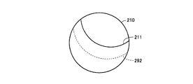
- FIG. 11 shows a state where the cuff 150 is wound around the measurement site with a too weak winding strength.
- FIG. 12 shows a boundary line in a state where the cuff 150 is wound around the measurement site with a winding strength that is too strong.
- FIG. 10 the boundary line 291 is located along the indicator 211.
- FIG. 11 shows a state in which the boundary line 292 is positioned below the indicator 211.
- FIG. 12 shows a state where the boundary line 293 is located above the indicator 211.
- the position of the boundary line between the fluid 221 and the fluid 222 in the fluid bag 201 that can be visually recognized from the window 210 changes according to the winding strength of the cuff 150 around the measurement site.
- the person being measured can determine whether or not the winding strength of the cuff 150 with respect to the measurement site is appropriate by visually recognizing the position of the boundary line in the window 210.
- An indicator 211 is attached to the window 210 of the present embodiment.
- the person to be measured of the sphygmomanometer 100 can determine whether or not the cuff 150 is wound around the measurement site with an appropriate winding strength based on the positional relationship between the boundary line and the indicator 211.
- the window 210 may be provided with only an indicator 211 indicating a boundary when the cuff 150 is wound with an appropriate winding strength, as shown in FIGS. Further, as shown in FIG. 13, an indicator 211 indicating a state where the winding strength is appropriate, an indicator 212 indicating a state where the winding strength is too high, and an indicator indicating a boundary when the winding strength is too low. 213 may be attached.
- the indicator 211 is provided so as to divide the surface of the window 210 into a plurality of regions in order to indicate the boundary lines of the plurality of fluids in the fluid bag 201. .
- the window 210 forms a plane that intersects the horizontal plane.
- the specific gravity of the fluid 221 and the fluid 222 differs. From this, in the sphygmomanometer 100 according to the present embodiment, a plurality of figures generated by dividing the window 210 by the indicator 211 are all in a circular level used in a washing machine or the like. Unlike a circle having the same center as the center of the outer circle, the figure has a center at a position different from the center of the window 210.
- FIG. 14 shows a modification in which a plurality of winding strength instruction units 200A to 200C are arranged along the direction intersecting the winding direction in the cuff 150 of the sphygmomanometer 100.
- FIG. 15 shows a state in which the cuff 150 of the modified example shown in FIG. 14 is wound around the arm A of the measurement subject.
- the winding direction of the cuff 150 around the measurement site (arm A) is indicated by an arrow A2
- the direction intersecting the winding direction is indicated by an arrow A3.
- the winding strength instruction units 200A to 200C have the same configuration as the winding strength instruction unit 200 described with reference to FIG. 4 and the like, and have windows 210A to 210C, respectively. Each of the windows 210A to 210C is provided with indicators 211A to 211C (corresponding to the indicator 211).
- the cuff 150 is wound around the measurement site so that the winding strength instruction units 200A to 200C are disposed at positions slightly inside the front of the measurement subject. Is intended. Accordingly, it is assumed that the boundary between the fluid 221 and the fluid 222 in the fluid bag 201 is located in each of the windows 210A to 210C when the cuff 150 is wound around the measurement site in the state shown in FIG. That is, in other words, it is arranged above the center of the windows 210A to 210C and at a position biased to the right in the left-right direction in FIG. This is so that the subject himself / herself can easily see the windows 210A to 210C of the winding strength instruction units 200A to 200C with the cuff 150 attached to the arm A.
- the cuff 150 is provided with a plurality of winding strength instruction units 200A to 200C along the direction intersecting the winding direction, so that the person to be measured can wind the cuff 150 in a wider range in the direction. It is possible to visually check whether the strength is appropriate.
- FIG. 16 shows a modification in which a plurality of winding strength instruction units 200D to 200F are arranged in the cuff 150 of the sphygmomanometer 100 along the winding direction.
- FIG. 17 shows a state in which the cuff 150 of the modified example shown in FIG. 16 is wound around the arm A of the measurement subject.
- the cuff 150 mainly includes the remaining winding strength instruction unit 200 ⁇ / b> D so that the winding strength instruction unit 200 ⁇ / b> F provided at the end is positioned in front of the measurement subject.
- 200E is intended to be wound around the arm A of the person being measured so as to be positioned inside the body of the person to be measured from the front.
- the winding strength instruction units 200D to 200F have windows 210D to 210F, respectively.
- Indicators 211D to 211F are attached to the windows 210D to 210F, respectively.
- the windows 210D to 210F are provided with indicators 211D to 211F in a manner corresponding to the position when the cuff 150 is wound.
- an indicator 211F is attached to the window 210F of the winding strength instruction unit 200F, which is considered to be positioned in front of the subject under wearing on the arm A, at a substantially central position in the left-right direction. Has been.
- the winding strength instruction part 200E is in a position rotated to the inside of the body of the subject along the winding direction indicated by the arrow A2 with respect to the winding strength instruction part 200F in a state of being attached to the arm A.
- an indicator 211E is attached to the window 210E of the winding strength instructing unit 200E at a position where the indicator 211F is rotated clockwise.
- the winding strength instruction part 200D is in a position rotated to the inside of the body of the subject along the winding direction indicated by the arrow A2 with respect to the winding strength instruction part 200E in a state of being attached to the arm A.
- the indicator D is attached to the window 210 ⁇ / b> D of the winding strength instructing unit 200 ⁇ / b> D at a position where the indicator 211 ⁇ / b> F rotates clockwise (more angle than the indicator 211 ⁇ / b> E).
- a plurality of winding strength instruction units 200D to 200F are provided along the winding direction (arrow A2) of the cuff 150, so that the person to be measured has a plurality of winding directions in the cuff 150. It is possible to visually recognize whether the winding strength is appropriate in position, that is, in a wider range.
- a plurality of winding strength instruction units 200D to 200F are arranged along the winding direction of the cuff 150, and further, a plurality of winding strength instruction units 200D to 200F are arranged along the direction intersecting with the winding direction.
- the winding strength instruction units 200A and 200C may be arranged.
- the winding strength instructing unit 200 has the characteristic of the presence state of a plurality of fluids (fluids 221 and 222) enclosed in the space formed by the fluid bag 201 and the window 210.
- the window 210 Through the window 210, the state of change due to the change in the magnitude of the force applied to the fluid bag 201 from the bag-shaped cover body 161 and the air bag 151 due to the change in the winding strength with respect to the measurement site is visually recognized through the window 210.
- the winding strength instruction unit 200 has a configuration in which its characteristics are changed so as to be visually recognized by a change in force applied from the air bag 151 and the bag-shaped cover body 161, a plurality of fluids as described above are enclosed. It is not limited to the configuration.
- the sphygmomanometer 100 is a material that increases the light energy generated by the amount of mechanical energy applied from the outside (Xuo Man, “Understanding the power that cannot be seen in the blink of light”, (National Institute of Advanced Industrial Science and Technology, Kyushu Center, Internet ⁇ www.techno-qanda.net/Collection-10/Collection-15/Collection-102/Collection-470/Collection-2215/Document-16434/at_download/file>) and the magnitude of external force Materials that change the color of light (AnneTrafton, “MIT gel changes color on demand”, October 21, 2007, Internet ⁇ http://web.mit.edu/newsoffice/2007/lightgels-1021.html>) By using this, it is possible to provide a configuration in which the winding strength can be visually recognized indirectly.
- the cuff 150 is wound with an appropriate winding strength as an indicator. It is preferable that a member representing a color assumed to emit light when the substance is attached to the cuff 150.
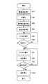
- FIG. 19 is a flowchart of blood pressure measurement processing executed in the sphygmomanometer 100.
- the sphygmomanometer 100 After the person to be measured visually wraps the winding strength instruction unit 200 (winding strength instruction units 200A to 200F), the cuff 150 is wound around the measurement site with an appropriate strength, and then the power switch 115A or the like is turned on.
- the blood pressure measurement process is executed by being operated.
- the control unit 122 is realized by executing a program stored in the memory unit 123 (or a recording medium detachable from the apparatus main body 110).
- control unit 122 first waits until operation is performed on power switch 115 ⁇ / b> A in step S ⁇ b> 10, and proceeds to step S ⁇ b> 20 when it is determined that the operation has been performed.
- step S20 the control unit 122 initializes the sphygmomanometer 100. Thereby, the internal pressure of the air bag 151 of the cuff 150 is initialized.
- control unit 122 accepts input of information for selecting a user by operating the user selection switch 115D. If it is determined that the information for selecting the user has been input, the control unit 122 proceeds to step S40.
- step S40 the control unit 122 waits until the measurement switch 115B is operated. If it is determined that the measurement switch 115B has been operated, the control unit 122 advances the process to step S50.
- step S50 the control unit 122 increases the cuff pressure by causing the pump 134 to send air to the air bag 151, and proceeds to step S60.
- step S60 the control unit 122 determines whether or not the cuff pressure has reached a predetermined pressure based on the output signal of the pressure sensor 132. Then, when it is determined that it has not yet reached, the control unit 122 returns the process to step S50, and when it is determined that it has reached, the process proceeds to step S70.
- step S70 the control unit 122 gradually reduces the cuff pressure by controlling the closed valve 135 to gradually open. Then, based on the pressure pulse wave signal superimposed on the signal detected by the pressure sensor 132 during such a decompression process, the control unit 122 calculates blood pressure (maximum blood pressure and minimum blood pressure) based on a predetermined procedure in step S80. calculate. If it is determined in step S90 that blood pressure calculation has been completed (YES in step S90), the process proceeds to step S100.
- step S100 the control unit 122 displays the blood pressure value obtained in step S80 on the display unit 114, and ends the blood pressure measurement process.
- the obtained blood pressure value is stored in the memory unit 123 in association with the user who accepted the selection in step S30.
- control unit 122 controls the valve 135 to be fully opened together with the display of the blood pressure value in step S100 (or after the display), and removes air from the air bag 151.
- the sphygmomanometer 100 that measures blood pressure by the oscillometric method is shown as an example of the blood pressure measuring device, but the blood pressure measuring method in the blood pressure measuring device according to the present invention is not limited to this.
- the present invention can be applied to a blood pressure measurement device that performs blood pressure measurement by other methods (for example, a microphone method).
Landscapes
- Health & Medical Sciences (AREA)
- Life Sciences & Earth Sciences (AREA)
- Cardiology (AREA)
- Vascular Medicine (AREA)
- Engineering & Computer Science (AREA)
- Medical Informatics (AREA)
- Physics & Mathematics (AREA)
- Ophthalmology & Optometry (AREA)
- Biophysics (AREA)
- Pathology (AREA)
- Dentistry (AREA)
- Biomedical Technology (AREA)
- Heart & Thoracic Surgery (AREA)
- Physiology (AREA)
- Molecular Biology (AREA)
- Surgery (AREA)
- Animal Behavior & Ethology (AREA)
- General Health & Medical Sciences (AREA)
- Public Health (AREA)
- Veterinary Medicine (AREA)
- Measuring Pulse, Heart Rate, Blood Pressure Or Blood Flow (AREA)
Abstract
Description
図1は、本発明の血圧測定装置の一実施の形態である血圧計の外観を示す斜視図である。
図2は、血圧計100の構成を示す機能ブロック図である。
図3は、血圧計100のカフ150を展開させた状態を示す図であり、図4は、図3中に示すIV-IV線に沿ったカフ150の断面図である。
図5は、血圧計100のカフ150を、測定部位に巻付けて固定した状態の一例である、被測定者の腕A(左腕)の上腕部に巻付けて固定した状態を示す。なお、図5において、矢印FRは、被測定者の正面から被測定者に向かう方向を示している。血圧計100のカフ150は、巻付強度指示部200が、正面よりも右側に位置するように、つまり、正面よりも体の内側に位置するように、測定部位に装着されることを意図している。
図10等に示されるように、窓210において、インジケータ211は、流体袋201内の複数の流体の境界線を指示するために、窓210の表面を複数の領域に区切るように設けられている。
[6-1.巻付方向に交わる方向に沿った配列]
本実施の形態の血圧計100において、巻付強度指示部200は、複数設けられることもできる。
図16は、血圧計100のカフ150において、その巻付方向に沿って複数の巻付強度指示部200D~200Fが配列された変形例を示す。図17は、図16に示した変形例のカフ150が被測定者の腕Aに巻付けられた状態を示す。
以上説明した本実施の形態では、巻付強度指示部200は、流体袋201と窓210によって構成される空間に封入された複数の流体(流体221,222)の存在態様という特性が、カフ150の測定部位に対する巻付強度が変化することによって、袋状カバー体161と空気袋151から流体袋201に加えられる力の大きさが変化することによって変化する状態を窓210を介して視認することにより、カフ150の巻付強度が適切であるか否かを視認することができた。
図19は、血圧計100において実行される血圧測定処理のフローチャートである。血圧計100では、被測定者が巻付強度指示部200(巻付強度指示部200A~200F)を視認することにより適切な強度で測定部位にカフ150を巻付けた後、電源スイッチ115A等が操作されて、血圧測定処理が実行される。なお、血圧計100では、制御部122が、メモリ部123(または、装置本体110に対して着脱可能な記録媒体)に記憶されたプログラムを実行することにより実現される。
以上説明した本実施の形態では、オシロメトリック法により血圧を測定する血圧計100が血圧測定装置の一例として示されたが、本発明に従う血圧測定装置における血圧測定方法はこれに限定されるものではなく、他の方法(たとえば、マイクロフォン法)による血圧測定を行なう血圧測定装置に対しても適用することができる。
Claims (6)
- 巻付けられることにより測定部位を圧迫するカフ(150)を備えた血圧測定装置(100)であって、
前記カフ(150)の外郭を覆う外装部(161)と、
前記外装部(161)内に設けられた第1の流体袋(151)と、
前記カフ(150)に、前記外装部(161)および前記第1の流体袋(151)に当接するように設けられた指示部材(200)とを備え、
前記指示部材(200)は、前記外装部(161)と前記第1の流体袋(151)から押圧される力の大きさに応じて、特性が視認可能に変化する、血圧測定装置(100)。 - 前記指示部材(200)は、一定の力で押圧された際に体積変化量の異なる複数の流体を封入された第2の流体袋(201)を含む、請求項1に記載の血圧測定装置(100)。
- 前記指示部材(200)は、前記特性の変化を表示する表示部(210)を含み、
前記表示部(210)には、前記外装部(161)と前記第1の流体袋(151)から前記第2の流体袋(201)が押圧される力の大きさを示すインジケータが設けられ、
前記インジケータは、前記表示部(210)に記載された、前記表示部(210)の中心とは異なる位置に中心を有する図形である、請求項2に記載の血圧測定装置(100)。 - 複数の前記指示部材(200A~200C)を備え、
複数の前記指示部材(200A~200C)は、前記カフ(150)の測定部位における巻付け方向に交わる方向に配列される、請求項1に記載の血圧測定装置(100)。 - 複数の前記指示部材(200D~200F)を備え、
複数の前記指示部材(200D~200F)は、前記カフ(150)の測定部位における巻付け方向に沿って配列される、請求項1に記載の血圧測定装置(100)。 - 前記外装部(161)と前記第1の流体袋(151)から前記指示部材(200)が押圧される力の大きさを示すインジケータ(211)をさらに備える、請求項1に記載の血圧測定装置(100)。
Priority Applications (3)
| Application Number | Priority Date | Filing Date | Title |
|---|---|---|---|
| DE112011101140T DE112011101140T5 (de) | 2010-03-30 | 2011-02-09 | Blutdruckmesseinrichtung |
| CN201180017816XA CN102858235A (zh) | 2010-03-30 | 2011-02-09 | 血压测定装置 |
| US13/632,805 US20130030311A1 (en) | 2010-03-30 | 2012-10-01 | Blood pressure measurement device |
Applications Claiming Priority (2)
| Application Number | Priority Date | Filing Date | Title |
|---|---|---|---|
| JP2010077971A JP2011206325A (ja) | 2010-03-30 | 2010-03-30 | 血圧測定装置 |
| JP2010-077971 | 2010-03-30 |
Related Child Applications (1)
| Application Number | Title | Priority Date | Filing Date |
|---|---|---|---|
| US13/632,805 Continuation US20130030311A1 (en) | 2010-03-30 | 2012-10-01 | Blood pressure measurement device |
Publications (1)
| Publication Number | Publication Date |
|---|---|
| WO2011122124A1 true WO2011122124A1 (ja) | 2011-10-06 |
Family
ID=44711865
Family Applications (1)
| Application Number | Title | Priority Date | Filing Date |
|---|---|---|---|
| PCT/JP2011/052763 Ceased WO2011122124A1 (ja) | 2010-03-30 | 2011-02-09 | 血圧測定装置 |
Country Status (5)
| Country | Link |
|---|---|
| US (1) | US20130030311A1 (ja) |
| JP (1) | JP2011206325A (ja) |
| CN (1) | CN102858235A (ja) |
| DE (1) | DE112011101140T5 (ja) |
| WO (1) | WO2011122124A1 (ja) |
Families Citing this family (4)
| Publication number | Priority date | Publication date | Assignee | Title |
|---|---|---|---|---|
| US9380502B2 (en) * | 2012-12-05 | 2016-06-28 | Telefonaktiebolaget L M Ericsson (Publ) | Determining the need for a routing area update for packet switched handover in multi-operator core network |
| US10292062B2 (en) * | 2014-01-31 | 2019-05-14 | Telefonaktiebolaget Lm Ericsson (Publ) | Resource allocation amongst parties sharing the same radio access network |
| WO2016198104A1 (en) * | 2015-06-11 | 2016-12-15 | Nec Europe Ltd. | Network management system and method for a shared radio access network, ran, infrastructure |
| JP7517087B2 (ja) * | 2020-11-04 | 2024-07-17 | オムロンヘルスケア株式会社 | 血圧測定用カフおよび血圧計 |
Citations (2)
| Publication number | Priority date | Publication date | Assignee | Title |
|---|---|---|---|---|
| JP2005305028A (ja) * | 2004-04-26 | 2005-11-04 | Omron Healthcare Co Ltd | 血圧測定用帯の巻付け制御装置および方法 |
| JP2009297161A (ja) * | 2008-06-11 | 2009-12-24 | Omron Healthcare Co Ltd | 血圧情報測定装置および血圧情報を測定するための方法 |
Family Cites Families (10)
| Publication number | Priority date | Publication date | Assignee | Title |
|---|---|---|---|---|
| US2558805A (en) * | 1946-08-09 | 1951-07-03 | Constantin P Yaglou | Pressure measuring |
| JPH02114934A (ja) | 1988-10-24 | 1990-04-27 | Terumo Corp | 電子血圧計 |
| JP2003164428A (ja) * | 2001-12-03 | 2003-06-10 | Tk Inc Co | 血圧測定用腕帯 |
| CN100353912C (zh) * | 2003-03-11 | 2007-12-12 | 泰尔茂株式会社 | 血压计用套箍以及设有该套箍的血压计 |
| JP4938024B2 (ja) * | 2005-12-14 | 2012-05-23 | コーニンクレッカ フィリップス エレクトロニクス エヌ ヴィ | 切断された肢が原因による出血を制御するための高密度焦点式超音波の誘導及び適用のためのトランスデューサ・カフ |
| JP2007275483A (ja) | 2006-04-12 | 2007-10-25 | Omron Healthcare Co Ltd | 血圧計用カフ |
| JP4134234B1 (ja) | 2007-02-05 | 2008-08-20 | シチズンホールディングス株式会社 | 電子血圧計 |
| US20080243010A1 (en) * | 2007-03-30 | 2008-10-02 | General Electric Company | System and method for facilitating proper cuff use during non-invasive blood pressure measurement |
| JP5061848B2 (ja) * | 2007-10-29 | 2012-10-31 | セイコーエプソン株式会社 | センサ装着用バンド及び生体情報機器 |
| US9750629B2 (en) * | 2009-09-18 | 2017-09-05 | Ethicon Endo-Surgery, Inc. | Implantable restriction system tension release mechanism |
-
2010
- 2010-03-30 JP JP2010077971A patent/JP2011206325A/ja not_active Withdrawn
-
2011
- 2011-02-09 WO PCT/JP2011/052763 patent/WO2011122124A1/ja not_active Ceased
- 2011-02-09 DE DE112011101140T patent/DE112011101140T5/de not_active Withdrawn
- 2011-02-09 CN CN201180017816XA patent/CN102858235A/zh active Pending
-
2012
- 2012-10-01 US US13/632,805 patent/US20130030311A1/en not_active Abandoned
Patent Citations (2)
| Publication number | Priority date | Publication date | Assignee | Title |
|---|---|---|---|---|
| JP2005305028A (ja) * | 2004-04-26 | 2005-11-04 | Omron Healthcare Co Ltd | 血圧測定用帯の巻付け制御装置および方法 |
| JP2009297161A (ja) * | 2008-06-11 | 2009-12-24 | Omron Healthcare Co Ltd | 血圧情報測定装置および血圧情報を測定するための方法 |
Also Published As
| Publication number | Publication date |
|---|---|
| DE112011101140T5 (de) | 2013-01-10 |
| US20130030311A1 (en) | 2013-01-31 |
| JP2011206325A (ja) | 2011-10-20 |
| CN102858235A (zh) | 2013-01-02 |
Similar Documents
| Publication | Publication Date | Title |
|---|---|---|
| CN102843963B (zh) | 血压测定装置 | |
| JP6179656B2 (ja) | 生体情報測定装置 | |
| JP4742576B2 (ja) | 血圧計用カフおよびこれを備えた血圧計 | |
| JP5853587B2 (ja) | 電子血圧計 | |
| JP2010057817A (ja) | 電子血圧計 | |
| JP2006326293A (ja) | 健康状態に応じて指標を与えるために心臓血管の働きを評価するための装置 | |
| WO2010055783A9 (ja) | 表示が改善された血圧測定装置 | |
| JP2006289088A (ja) | 脈拍検出装置および方法 | |
| WO2011122124A1 (ja) | 血圧測定装置 | |
| JP5487963B2 (ja) | 血圧情報測定装置用カフおよびこれを備えた血圧情報測定装置 | |
| JP6747332B2 (ja) | 血圧情報測定装置 | |
| JP2011177249A (ja) | 血圧情報測定装置および血圧情報測定装置用カフの装着状態判別方法 | |
| JP2007275483A (ja) | 血圧計用カフ | |
| JP5223590B2 (ja) | 血圧計 | |
| CN108778103B (zh) | 血压脉搏波测定装置 | |
| JP2010051364A (ja) | 手首式血圧計 | |
| JP5141679B2 (ja) | 血圧情報測定装置用カフおよびこれを備えた血圧情報測定装置 | |
| CN107708534B (zh) | 血压测量装置 | |
| JP2012115413A (ja) | 電子血圧計 | |
| JP2009297353A (ja) | 電子血圧計 | |
| WO2011122126A1 (ja) | 測定部位に手動で巻付けられるカフを有する血圧測定装置 | |
| JP2007185233A (ja) | 血圧測定装置 | |
| KR20190073123A (ko) | 휴대성이 용이한 혈압 및 당뇨측정기 | |
| WO2019202856A1 (ja) | 電子血圧計および心不全検出器 | |
| JP2011041684A (ja) | 生体情報計測装置 |
Legal Events
| Date | Code | Title | Description |
|---|---|---|---|
| WWE | Wipo information: entry into national phase |
Ref document number: 201180017816.X Country of ref document: CN |
|
| 121 | Ep: the epo has been informed by wipo that ep was designated in this application |
Ref document number: 11762365 Country of ref document: EP Kind code of ref document: A1 |
|
| WWE | Wipo information: entry into national phase |
Ref document number: 1120111011407 Country of ref document: DE Ref document number: 112011101140 Country of ref document: DE |
|
| 122 | Ep: pct application non-entry in european phase |
Ref document number: 11762365 Country of ref document: EP Kind code of ref document: A1 |