WO2011121639A1 - 支持マウントブラケット、フロントディファレンシャルギヤユニットの搭載方法、及び、フロントディファレンシャルギヤユニットの取付構造 - Google Patents
支持マウントブラケット、フロントディファレンシャルギヤユニットの搭載方法、及び、フロントディファレンシャルギヤユニットの取付構造 Download PDFInfo
- Publication number
- WO2011121639A1 WO2011121639A1 PCT/JP2010/002281 JP2010002281W WO2011121639A1 WO 2011121639 A1 WO2011121639 A1 WO 2011121639A1 JP 2010002281 W JP2010002281 W JP 2010002281W WO 2011121639 A1 WO2011121639 A1 WO 2011121639A1
- Authority
- WO
- WIPO (PCT)
- Prior art keywords
- mount
- vehicle
- gear unit
- width direction
- differential gear
- Prior art date
- Legal status (The legal status is an assumption and is not a legal conclusion. Google has not performed a legal analysis and makes no representation as to the accuracy of the status listed.)
- Ceased
Links
Images
















Classifications
-
- B—PERFORMING OPERATIONS; TRANSPORTING
- B62—LAND VEHICLES FOR TRAVELLING OTHERWISE THAN ON RAILS
- B62D—MOTOR VEHICLES; TRAILERS
- B62D21/00—Understructures, i.e. chassis frame on which a vehicle body may be mounted
-
- B—PERFORMING OPERATIONS; TRANSPORTING
- B60—VEHICLES IN GENERAL
- B60K—ARRANGEMENT OR MOUNTING OF PROPULSION UNITS OR OF TRANSMISSIONS IN VEHICLES; ARRANGEMENT OR MOUNTING OF PLURAL DIVERSE PRIME-MOVERS IN VEHICLES; AUXILIARY DRIVES FOR VEHICLES; INSTRUMENTATION OR DASHBOARDS FOR VEHICLES; ARRANGEMENTS IN CONNECTION WITH COOLING, AIR INTAKE, GAS EXHAUST OR FUEL SUPPLY OF PROPULSION UNITS IN VEHICLES
- B60K15/00—Arrangement in connection with fuel supply of combustion engines or other fuel consuming energy converters, e.g. fuel cells; Mounting or construction of fuel tanks
- B60K15/03—Fuel tanks
- B60K15/063—Arrangement of tanks
-
- B—PERFORMING OPERATIONS; TRANSPORTING
- B60—VEHICLES IN GENERAL
- B60K—ARRANGEMENT OR MOUNTING OF PROPULSION UNITS OR OF TRANSMISSIONS IN VEHICLES; ARRANGEMENT OR MOUNTING OF PLURAL DIVERSE PRIME-MOVERS IN VEHICLES; AUXILIARY DRIVES FOR VEHICLES; INSTRUMENTATION OR DASHBOARDS FOR VEHICLES; ARRANGEMENTS IN CONNECTION WITH COOLING, AIR INTAKE, GAS EXHAUST OR FUEL SUPPLY OF PROPULSION UNITS IN VEHICLES
- B60K17/00—Arrangement or mounting of transmissions in vehicles
- B60K17/22—Arrangement or mounting of transmissions in vehicles characterised by arrangement, location, or type of main drive shafting, e.g. cardan shaft
- B60K17/24—Arrangement of mountings for shafting
-
- B—PERFORMING OPERATIONS; TRANSPORTING
- B62—LAND VEHICLES FOR TRAVELLING OTHERWISE THAN ON RAILS
- B62D—MOTOR VEHICLES; TRAILERS
- B62D21/00—Understructures, i.e. chassis frame on which a vehicle body may be mounted
- B62D21/02—Understructures, i.e. chassis frame on which a vehicle body may be mounted comprising longitudinally or transversely arranged frame members
-
- B—PERFORMING OPERATIONS; TRANSPORTING
- B62—LAND VEHICLES FOR TRAVELLING OTHERWISE THAN ON RAILS
- B62D—MOTOR VEHICLES; TRAILERS
- B62D21/00—Understructures, i.e. chassis frame on which a vehicle body may be mounted
- B62D21/11—Understructures, i.e. chassis frame on which a vehicle body may be mounted with resilient means for suspension, e.g. of wheels or engine; sub-frames for mounting engine or suspensions
Definitions
- the present invention provides a mounting bracket for supporting a mount portion of a front differential gear unit, a method for mounting the front differential gear unit on a vehicle frame, and a method of mounting the front differential gear unit on the vehicle frame. It belongs to the technical field related to the mounting structure.
- a small truck or a vehicle called an SUV Sports Utility Vehicle
- a ladder-like chassis frame as described in Patent Documents 1 and 2, for example.
- the chassis frame is formed in a ladder shape by a pair of left and right main frames (also called side frames) extending in the vehicle length direction (vehicle longitudinal direction) and a plurality of cross members connecting the main frames.
- the power of the engine disposed in the engine room located at the front of the vehicle is transmitted to the rear wheels via the transmission, the propeller shaft, and the rear differential gear unit.
- a power transfer unit is provided between the transmission and the propeller shaft, and the output of the transmission is transmitted to the front and rear wheels via the power transfer unit. And distributed.
- the front differential gear unit is attached to the front portion of the chassis frame.
- the front differential gear unit has a cylindrical rubber bush and a central shaft that passes through the central portion (center hole) of the rubber bush in order to suppress the vibration from being transmitted to the chassis frame. It is elastically supported by the chassis frame via a plurality of (usually three to four) mounts. Each of the mounts is attached to and supported by a mount bracket provided on the chassis frame.
- the distance between the left and right main frames is narrow, and two cross members for supporting the arms of the front wheel suspension device are provided.
- the front differential gear unit needs to be mounted in a narrow space surrounded by the frame and the cross member.
- the present invention has been made in view of such a point, and an object of the present invention is to improve the mountability of the front differential gear unit to the vehicle frame and to mount the front differential gear unit in a narrow space.
- the task is to make it easier.
- the frame is a pair of left and right extending in the vehicle length direction.
- the support frame has a main frame and a cross member connecting the pair of main frames, and the support mount bracket is disposed at a portion of the cross member that is shifted in the vehicle width direction from the center in the width direction of the vehicle itself.
- a base portion coupled to the cross member, and a pair of fixing portions projecting from the base portion and sandwiching the mount portion from both sides in the vehicle width direction.
- the fixing part on the side close to the center in the width direction is detachably attached to the base part.
- the mount portion of the front differential gear unit is supported by the support mount bracket disposed on the cross member at a position shifted in the vehicle width direction from the center in the width direction of the vehicle itself (the center axis in the vehicle width direction).
- the pair of fixing portions are each configured by a plate-like member, and the base portion is detachably fixed from the cross member for detachably mounting and fixing the detachable fixing portion.
- a fixing portion that protrudes toward the portion side, and the removable fixing portion includes a first hole portion through which a fixing portion fastening bolt for fastening the fixing portion to the mounting portion is inserted, and the fixing portion fastening It is preferable that a second hole portion is formed which passes through the mount portion in parallel with the bolt and through which a mount portion fastening bolt for fastening the mount portion to the pair of fixing portions is inserted.
- the detachable fixing portion serves both as fixing the fixing portion to the base portion (attachment portion) and supporting the mounting portion, so that the mounting portion can be supported with high rigidity.
- the fixing part fastening bolt for fastening the detachable fixing part to the base and the mount part fastening bolt for fastening the mount part to the pair of fixing parts are parallel, these fastening operations are performed in one direction. Therefore, workability is improved.
- the fixing portion on the side farther from the center in the width direction of the vehicle is integrally formed with the base portion.
- the fixing portion fastening bolt is erected on the mounting portion so as to extend toward the center in the width direction of the vehicle. It is preferable that the nut to be screwed is attached to the fixed portion on the side far from the center in the width direction of the vehicle while being prevented from rotating.
- the detachable fixing portion is moved from the vehicle width direction center side with respect to the fixing portion fastening bolt, the fixing portion fastening bolt is inserted into the first hole portion, and the fixing portion fastening bolt is inserted in the vehicle width direction.
- a nut can be screwed from the center side.
- the mount portion fastening bolt is inserted into the second hole portion from the center in the vehicle width direction so as to pass through the mount portion and screwed to the nut that is prevented from rotating.
- an escape portion for avoiding an overlap with the outer shape of the mount portion supported by the support mount bracket is formed at the projecting tip portion of the attachment portion when viewed from the vehicle width direction.
- Such an escape portion facilitates the approach when the mount portion approaches the support mount bracket in the vehicle width direction without the mount portion interfering with the protruding tip portion of the mounting portion.
- the two fixing portion fastening bolts are erected on the attachment portion apart from each other, and the relief portion is located between the two fixing portion fastening bolts. Is preferable.
- the escape portion can be brought as close as possible to the cross member, and as a result, the mount portion can be attached to the support mount bracket in a state as close as possible to the cross member. Therefore, the supportability of the mount part by the support mount bracket is improved.
- an engine mount bracket that protrudes from the pair of main frames to the center side in the width direction of the vehicle is provided behind the cross member, and a part of the front differential gear unit is formed by the two engines. It is located between the mount bracket and the cross member, the mount part is provided at the front part of the front differential gear unit, and the support mount bracket is provided at the rear part of the cross member. Also good.
- the mount portion is prevented while avoiding interference between the front differential gear unit and the engine mount bracket.
- the support mount bracket can be moved from the center in the vehicle width direction toward the support mount bracket in the vehicle width direction to approach the support mount bracket.
- Another aspect of the present invention is a method of mounting a front differential gear unit on a vehicle frame
- the mounting method includes a first mount in which the front differential gear unit is provided at a front portion of the front differential gear unit.
- the portion is provided at a position shifted in the vehicle width direction from the center in the width direction of the vehicle itself in the frame, closer to the center in the width direction of the vehicle than the first mount bracket for supporting the first mount portion.
- a front differential gear unit in a state where the first mount portion is positioned closer to the center in the width direction of the vehicle than the first mount bracket, and the first mount portion includes the first mount portion.
- the above mounting method makes it possible to attach the first mount portion of the front differential gear unit to the first mount bracket from the center side in the vehicle width direction with a relatively wide work space, and the attachment work becomes easy.
- the vehicle of the front differential gear unit is provided. It is preferable that the method further includes a step of supporting a third mount portion provided at the other end portion in the width direction on a third mount bracket provided on the frame.
- the entire front differential gear unit can be supported in a well-balanced manner. That is, the front differential gear unit usually has a gear housing portion (a differential gear is housed therein) that has the largest weight, and the first mount portion and one of the second and third mount portions are connected to each other. The most significant weight of the front differential gear unit is supported, and the remaining one mounting portion (second or third mounting portion) functions to stop the swinging of the front differential gear unit about the axis extending in the front-rear direction. .
- the first mount portion which is particularly important from the viewpoint of supporting the gear unit and preventing vibration, is first attached to the first mount bracket, so that the first mount portion is attached to the first mount bracket. Positioning and mounting can be ensured, and gear unit support and vibration prevention can be ensured.
- Still another aspect of the present invention is a structure for attaching a front differential gear unit to a vehicle frame.
- the frame includes a pair of left and right main frames extending in the vehicle length direction, and the pair of main frames.
- a cross member that connects between the frames, and is attached to a portion of the rear portion of the cross member near one of the main frames, and supports a first mount portion provided at a front portion of the front differential gear unit.
- a first mount bracket, and the first mount bracket includes a base portion coupled to the cross member, and a pair of fixing portions that protrude from the base portion and support the mount portion from both sides in the vehicle width direction.
- a fixing part far from the one main frame of the pair of fixing parts Removably attached to.
- the first mounting portion of the front differential gear unit can be used as the first mounting bracket from the center side in the vehicle width direction with a relatively large working space. It can be attached, and the attaching operation becomes easy.
- the pair of fixed portions are each configured by a plate-like member, and the first mount portion includes a cylindrical rubber bush and a central shaft that passes through the central portion of the rubber bush.
- the rubber bush of the first mount portion is sandwiched between the pair of fixed portions, and the central axis of the first mount portion is the center of the rubber bush of the first mount portion in the vehicle width direction. It is preferable to be fixed to the pair of fixing portions in a state of penetrating through the two.
- the first mount portion can be positioned and attached to the first mount bracket in the vehicle width direction, the vehicle length direction, and the vertical direction so that the rubber bush of the first mount portion is not twisted. (That is, to effectively absorb vibration).
- the base portion of the first mount bracket has a mounting portion protruding from the cross member toward the detachable fixing portion for detachably mounting and fixing the detachable fixing portion.
- the detachable fixing part can be easily attached to the base part (attachment part), and the first mount part can be easily attached to the first mount bracket.
- a fixing portion closer to the one main frame among the pair of fixing portions is integrally formed with the base.
- second and third mount portions are respectively provided at both ends of the front differential gear unit in the vehicle width direction, and the first to third mount portions are cylindrical.
- Each of which has a cylindrical rubber bush and a central axis that passes through the central portion of the rubber bush, and the frame further includes another cross member that connects the pair of main frames behind the cross member.
- a second cross-mount member mounted on the other cross member in the vicinity of the other main frame and supporting the second mount portion; and attached to the one main frame and supporting the third mount portion.
- a third mount bracket wherein the first mount portion includes the first mount bracket.
- the second mount portion is attached to the second mount bracket so that the central axis of the second mount portion extends in the vertical direction.
- the third mount portion is attached to the third mount bracket so that a central axis of the third mount portion extends in the vehicle length direction.
- the first mount portion is positioned in the vehicle width direction, the vehicle length direction, and the vertical direction with respect to the first mount bracket. Are preferably attached.
- the entire front differential gear unit when the front differential gear unit is attached to the vehicle frame, the entire front differential gear unit can be mounted in the vehicle width direction, the vehicle length direction, and the vertical direction only by first attaching the first mount portion to the first mount bracket. It can be positioned approximately in the direction. As a result, the mounting work of the second and third mounts is facilitated. Further, by positioning and attaching the first mount portion to the first mount bracket, the rubber bush of the first mount portion can be prevented from being twisted to effectively absorb vibration.
- the rubber bush of the second mount portion When positioning the first mount portion as described above, the rubber bush of the second mount portion is placed on the upper surface of the second mount bracket, and the central axis of the second mount portion is the second mount portion.
- the rubber bush is fixed to the second mount bracket in a state of passing through the central portion of the rubber bush in the vertical direction, and the central axis of the third mount portion penetrates the rubber bush of the third mount portion in the vehicle length direction.
- both ends of the central shaft protrude to the front side and the rear side of the rubber bush, respectively, and the protruding both ends are placed on the upper surface of the third mount bracket. It is preferably fixed to the mounting bracket.
- the suspension by the suspension device is not required after the first mount portion is attached to the first mount bracket.
- the front differential gear unit can be removed from the suspension device.
- the mountability of the front differential gear unit to the vehicle frame is improved, and the installation work of the front differential gear unit in a narrow space is facilitated.
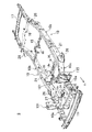
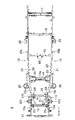
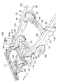
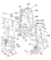
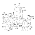
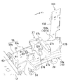
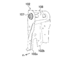
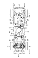
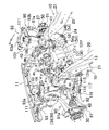
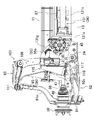
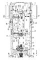
- FIG. 1 is a perspective view showing an entire vehicle to which a frontal collision energy absorption structure according to an embodiment of the present invention is applied. It is the perspective view seen from the vehicle left diagonal front side and the upper side which shows the whole chassis frame of the said vehicle. It is a top view of the said chassis frame. It is the perspective view seen from the vehicle left diagonal rear side and the upper side which shows the vehicle front side part of the said chassis frame. It is the perspective view seen from the vehicle left diagonal rear side and the lower side which shows the vehicle front side part of the said chassis frame. It is a perspective view which shows the suspension tower vicinity in the vehicle width direction outer side part of the main frame of the left side of the said chassis frame.
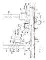
- FIG. 18 is a sectional view taken along line XIX-XIX in FIG. 17.
- FIG. 15 is a sectional view taken along line XXI-XXI in FIG. 14 (however, most of the mounted components shown in FIG. 20 are omitted).
- FIG. 23 is a sectional view taken along line XXIII-XXIII in FIG. 22. It is a bottom view which shows the vehicle rear side part of the chassis frame which mounts the said components. It is a perspective view which shows the principal part of the chassis frame before a front differential gear unit attachment.
- FIG. 26 is a view corresponding to FIG.
- FIG. 25 illustrating a step in the middle of attachment of the front differential gear unit.
- FIG. 26 is a view corresponding to FIG. 25 illustrating a step in the middle of attachment of the front differential gear unit.
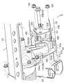
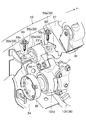
- It is a disassembled perspective view of the 1st mount bracket vicinity which shows the mode of attachment to the 1st mount bracket of a 1st mount.
- It is a perspective view of the 1st mount bracket vicinity which shows the attachment completion state to the 1st mount bracket of a 1st mount.
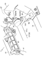
- It is a perspective view of the 2nd mount bracket vicinity which shows the mode of attachment to the 2nd mount bracket of a 2nd mount.
- It is a perspective view of the 3rd mount bracket vicinity which shows the mode of attachment to the 3rd mount bracket of a 3rd mount.
- It is a side view which shows the middle stage of the front differential gear unit removal at the time of service.
- It is a side view which shows the middle stage of the front differential gear unit removal at the time of service.
- FIG. 1 shows the entirety of a vehicle 1 (in this embodiment, a small truck) to which a frontal collision energy absorbing structure according to an embodiment of the present invention is applied.
- 2 to 12 show the whole or a part of the chassis frame 9 (vehicle frame) of the vehicle 1
- FIGS. 13 to 24 show various components (including units) mounted on the chassis frame 9.
- FIGS. 25 to 31 are views for explaining a method of attaching a front differential gear unit 36, which will be described later, to the chassis frame 9, and
- FIGS. 32 and 33 are methods of removing the front differential gear unit at the time of service. It is a figure for demonstrating.
- the vehicle 1 includes an engine room 2, a cabin 3, and a loading platform 4 in order from the front side.
- the front, rear, left and right of the vehicle 1 are simply referred to as front, rear, left and right, respectively.
- FIGS. 2 to 18, 20 to 22, and FIGS. 24 to 33 the front side of the vehicle 1 is described as Fr.
- the vehicle 1 has a chassis frame 9 at the lower part thereof.
- the chassis frame 9 includes a pair of left and right main frames 10 (also referred to as side frames) extending in the vehicle length direction (front-rear direction) and a plurality (in this embodiment) extending in the vehicle width direction connecting the main frames 10. , 7) (hereinafter, referred to as first to seventh cross members 11 to 17 in order from the front) and has a ladder shape in plan view.
- Each main frame 10 is formed in a substantially rectangular cross section by an inner panel 20 on the inner side in the vehicle width direction and an outer panel 21 on the outer side in the vehicle width direction, and a closed cross-sectional space is formed between these panels 20 and 21. .
- the first cross member 11 is attached to the front ends of both main frames 10 and functions as a bumper reinforcement that reinforces the front bumper 5 (see FIG. 1).
- the second cross member 12 is attached to the left and right main frames 10 via cross member brackets 23 welded to the left and right main frames 10 at both ends thereof.
- the third cross member 13 is also attached to the left and right main frames 10 via cross member brackets 24 welded to the left and right main frames 10 at both ends thereof.
- the cross member bracket 23 can be regarded as a part of the second cross member 12, and the cross member bracket 24 can be regarded as a part of the third cross member 13.
- the fourth cross member 15 is attached to the left and right main frames 10 via large gussets 25 respectively welded to the left and right main frames 10 at both ends thereof.
- the gusset 25 has a role of a bracket and a role of reinforcement, and can be regarded as a part of the fourth cross member 15. Both end portions of the fifth to seventh cross members 15 to 17 are directly attached to the left and right
- Each main frame 10 is located at both ends of the lower part of the engine room 2 in the vehicle width direction and has a narrow width portion 10a where the distance between the main frames 10 is small, and is located below the cabin 3 and the loading platform 4 and both.
- the space between the main frames 10 is located between the wide portion 10b where the interval between the main frames 10 is larger than the narrow portion 10a, and between the narrow portion 10a and the wide portion 10b (the rear end portion of the engine room 2).
- each wide portion 10b itself is larger than the width (that is, the cross-sectional area) of each narrow portion 10a itself.
- Each widened portion 10c extends from the rear end (near the rear side of the third cross member) of each narrow-width portion 10a so as to be inclined rearward in the vehicle width direction, and the width of the widened portion 10c itself toward the rear side. (Cross sectional area) becomes large and is connected to the front end (near the front side of the fourth cross member 14) of the wide portion 10b.
- the widened portion 10c and the third and fourth cross members 13 and 14 of both main frames 10 have a trapezoidal shape in plan view.
- the wide width portion 10b is formed so that the width (cross-sectional area) of the wide width portion 10b itself is the largest at the connecting portion with the fourth cross member 14 or in the vicinity thereof.
- the fourth cross member 14 is connected to a portion having a large width (cross-sectional area) in the wide width portion 10 b, and the connection portion is reinforced by the large gusset 25.
- a portion of the wide frame portion 10b of each main frame 10 located below the cabin 3 is at a lower height than the narrow width portion 10a, and the wide width portion 10c is inclined downward toward the rear. Yes.
- the portion located below the loading platform 4 in the wide portion 10b of each main frame 10 (the portion behind the sixth cross member 16) is more than the portion located below the cabin 3 in the wide portion 10b.
- the rear portion of the portion located on the upper side and positioned on the lower side of the cabin 3 in the wide portion 10b is inclined upward (see FIG. 14).
- a cab mount bracket 26 is attached in the vicinity of the front side of the fourth cross member 14 in the widened portion 10c of each main frame 10 and in the vicinity of the front side of the sixth cross member 16 in the wide width portion 10b.
- a vehicle body member constituting the cabin 3 is placed on each cab mount bracket 26 via a cab mount having a rubber member.
- the cab mount bracket 26 is attached to the outer surface and the lower surface of the main frame 10 in the vehicle width direction by welding.
- the vehicle body member constituting the floor of the cabin 3 is a floor panel 28, and the vehicle body member that partitions the engine room 2 and the cabin 3 is a dash. Panel 29.
- the lower end of the dash panel 29 is connected to the front end of the floor panel 28.
- the rear end portion of the floor panel 28 is bent upward to partition the cabin 3 and the loading platform 4.
- the drive system of the vehicle 1 includes an engine 32, a transmission 33, a power transfer unit 34, a front wheel propeller shaft 35, a front differential gear unit 36 (hereinafter simply referred to as a gear unit 36), and a rear wheel.
- a propeller shaft 37 and a rear differential gear unit 38 are provided.
- the vehicle 1 is a four-wheel drive vehicle (4WD vehicle) that drives the front wheels 6 and the rear wheels 7.
- 4WD vehicle four-wheel drive vehicle
- the power transfer unit 34, the front wheel propeller shaft 35, and the gear unit 36 are present in excess as compared with the 2WD vehicle that drives only the rear wheel 7.
- the engine 32 is a vertical engine having a plurality of (in this embodiment, five) cylinders arranged in a row in the vehicle length direction, and a transmission 33 is connected to the rear side of the engine 32.
- brackets 40 are attached to the left and right side surfaces of the engine 32 so as to protrude to the left and right sides, respectively.
- An engine mount 41 having a cylindrical rubber bush 41a is held at the tip of each bracket 40 so that the central axis of the rubber bush 41a extends in the vehicle length direction.
- the engine mount 41 further includes a central shaft 41b that penetrates the central portion of the rubber bush 41a in the vehicle length direction, and support members 41c that support both ends of the central shaft 41b.
- the engine mount bracket 27 is attached to the narrow portion 10a of both main frames 10 so as to be positioned below the support member 41c.
- a support member 41 c is attached on the engine mount bracket 27, whereby the engine 32 is elastically supported on the engine mount bracket 27 via the bracket 40 and the engine mount 41.
- each engine mount bracket 27 is welded to the inner surface of each main frame 10 in the vehicle width direction (the inner panel 20 of each main frame 10), and the vehicle width from the surface. It has an upper member 27a and a lower member 27b that protrude inward in the direction (the center in the width direction of the vehicle 1).
- the upper member 27a is formed such that a cross section cut along the vehicle length direction has a substantially inverted U shape
- the lower member 27b has a cross section cut along the vehicle length direction having a substantially U shape. It is formed to make.
- the side end portions on both sides in the vehicle length direction of the upper member 27a and the side end portions on both sides in the vehicle length direction of the lower member 27b are joined to each other.
- the front side end of the upper member 27a and the front side end of the lower member 27b are joined together, and the rear side end of the upper member 27a and the rear side end of the lower member 27b. Are joined together.
- a space is formed between the two members 27a and 27b, and the inside of the space in the vehicle width direction is open.
- a support member 41c of the engine mount 41 is attached to the upper surface of the upper member 27a via a reinforcing member 27c.
- a substantially U-shaped cutout portion 27d opened in the vehicle width direction is formed on the bottom surface portion (a portion extending horizontally) of the lower member 27b (see FIG. 9 and FIG. 9). (See FIG. 21).
- the notch 27d is formed so that the engine mount bracket 27 is crushed as much as possible in the vehicle length direction when the vehicle 1 collides with the front. Further, the vehicle length is located at a position (position corresponding to the space) that overlaps each engine mount bracket 27 in the vehicle length direction on the vehicle width direction inner surface of each main frame 10 (inner panel 20 of each main frame 10). A long hole 128 extending in the direction is formed (see FIG. 9). By this long hole 128, when the front collision of the vehicle 1 occurs, the mounting portion of the engine mount bracket 27 in the main frame 10 is crushed as much as possible in the vehicle length direction together with the engine mount bracket 27.
- the power transfer unit 34 is connected to the rear side of the transmission 33 and distributes the output of the transmission 33 to the front wheels 6 and the rear wheels 7.
- This power transfer unit 34 is supported via a rubber mount on a mount mounting portion 14a provided at the center in the vehicle width direction on the upper surface of the fourth cross member 14.
- a rear end of a front wheel propeller shaft 35 extending in the vehicle length direction is connected to the left side of the power transfer unit 34 (the portion protruding to the left), and the power transfer unit 34
- the rear end of 34 is connected to the front end of a propeller shaft 37 for rear wheels extending in the vehicle length direction.
- the rear end of the front wheel propeller shaft 35 is connected to the power transfer unit 34 via a constant velocity joint 44, and the front end of the front wheel propeller shaft 35 is connected to a gear unit 36 (details will be described later) via a constant velocity joint 45. Input shaft).
- the gear unit 36 is connected to the differential gear and the front-wheel propeller shaft 35 and extends in the vehicle length direction, and includes an input shaft for inputting power to the differential gear, a vehicle A left and right output shaft that extends in the width direction and transmits the output of the differential gear to the left and right front wheels 6 respectively, and a case 131 that accommodates the differential gear, the input shaft, and the left and right output shafts are provided.
- the case 131 includes a gear accommodating portion 131a that accommodates the differential gear, and left and right output shafts that extend from the gear accommodating portion 131a to both sides in the vehicle width direction (left and right sides) and accommodate the left and right output shafts, respectively.
- the left and right output shaft accommodating portions 131b and 131c have a cylindrical shape covering the periphery of the left and right output shafts, respectively.
- the rear end portion (constant velocity joint 45) of the input shaft protrudes from the rear end of the input shaft accommodating portion 131d.
- the gear housing 131a and the input shaft housing 131d are located on the left side of the engine 32 (that is, on the left side of the center in the width direction of the vehicle 1). It is closer to the left main frame 10 than the main frame 10. For this reason, the right output shaft accommodating portion 131c is longer in the vehicle width direction than the left output shaft accommodating portion 131b, and reaches the vicinity of the right main frame 10 through the lower side of the engine 32.
- a part of the gear unit 36 is located between the left and right engine mount brackets 27 (located behind the second cross member 12) and the second cross member 12.
- the output shafts are connected to left and right front wheel drive shafts 47 extending in the vehicle width direction through constant velocity joints housed in a boot 46, respectively.
- the shaft 47 is connected to a hub 50 that holds the wheels of the left and right front wheels 6 via a constant velocity joint accommodated in the boot 48. With these constant velocity joints, it is possible to cope with the movement of each front wheel 6 in the vertical direction with respect to the output shaft and the movement by steering described later.
- the power of the engine 32 is transmitted to the left and right front wheels 6 via the transmission 33, the power transfer unit 34, the front wheel propeller shaft 35, the gear unit 36, and the left and right front wheel drive shafts 47. .
- the gear unit 36 is attached to the chassis frame 9 at three locations and is elastically supported. Specifically, the position on the left side of the rear portion of the second cross member 12, that is, the second cross member 12 is shifted from the center in the width direction of the vehicle 1 itself (the center axis in the width direction of the vehicle 1) to the left in the vehicle width direction.
- a first mount bracket 57 for supporting the first mount 53 having a cylindrical rubber bush 53a is provided at the site (see FIGS. 3, 5, 6, 20, 21, and 25 to 29). ).
- the center in the width direction of the vehicle 1 coincides with the center in the vehicle width direction of the second cross member 12.
- a second mount bracket 58 for supporting a second mount 54 having a cylindrical rubber bush 54a on the right end portion (in practice, the upper surface of the cross member bracket 24) on the upper surface of the third cross member 13 is provided. It is provided so as to protrude forward (see FIGS. 3, 4, 15 to 17 and FIG. 30).
- a third mount having a cylindrical rubber bush 55a at the upper position of the third cross member 13 on the inner surface in the vehicle width direction of the left main frame 10 (the main frame 10 closer to the input shaft accommodating portion 131d).
- a third mount bracket 59 is provided to support 55 (see FIGS. 3, 4, 7-9, 17, 20, and 31).
- the third mount bracket 59 is divided into two parts, a front divided part 59a and a rear divided part 59b.
- the first mount 53 corresponds to the mount portion or the first mount portion of the present invention
- the first mount bracket 57 corresponds to the support mount bracket of the present invention
- the second mount 54 corresponds to the second mount portion of the present invention
- the third mount 55 corresponds to the third mount portion of the present invention.
- the first mount 53 further includes a central shaft 53b that passes through the central portion (central hole) of the rubber bush 53a. Both end portions of the central shaft 53 b are supported by the first mount bracket 57. In this supported state, the central shaft 53b extends in the vehicle width direction. That is, the first mount 53 is attached to the first mount bracket 57 so that the central shaft 53b of the first mount 53 extends in the vehicle width direction.
- the second mount 54 further includes a central shaft 54b that penetrates the central portion (central hole) of the rubber bush 54a.
- the central axis 54b extends in the vertical direction.
- One end portion (lower end portion) of the central shaft 54b is a male screw portion that is screwed with a female screw portion of a weld nut provided on the lower surface of the second mount bracket 58, and the other end portion (upper end portion) is a male screw portion. Hexagonal shape for engaging with a tool to be fastened to the part.
- the center shaft 54b is fixed to the second mount bracket 58 in a state of vertically passing through the center portion of the rubber bush 54a placed on the upper surface of the second mount bracket 58. That is, the second mount 54 is attached to the second mount bracket 58 so that the central axis 54b of the second mount 54 extends in the vertical direction.
- the third mount 55 further includes a central shaft 55b that passes through the central portion (central hole) of the rubber bush 55a.
- the central shaft 55b extends in the vehicle length direction. Both end portions of the central shaft 55b protrude to the front side and the rear side of the rubber bush 55a, respectively.
- the protruding both end portions are formed in a plate shape extending in the horizontal direction, and are respectively placed on the upper surfaces of the front-side divided portion 59a and the rear-side divided portion 59b. 20 and FIG. 31), it is fixed to the front divided portion 59a and the rear divided portion 59b, respectively. That is, the third mount 55 is attached to the third mount bracket 59 (the front divided portion 59a and the rear divided portion 59b) so that the central axis 55b of the third mount 55 extends in the vehicle length direction.
- a first mount holding portion 131e that protrudes forward and holds the periphery of the rubber bush 53a of the first mount 53 is formed at the front portion of the gear housing portion 131a of the gear unit 36 (FIGS. 20 and 20). 28 and FIG. 29).
- a second mount holding portion 131f that protrudes rearward and holds the periphery of the rubber bush 54a of the second mount 54 is formed at the tip end portion (right end portion) of the right output shaft housing portion 131c. (See FIGS. 15, 17 and 30).
- a third mount holding portion 131g that protrudes to the upper left side and holds the periphery of the rubber bush 55a of the third mount 55 is formed at the rear portion of the input shaft accommodating portion 131d (FIGS. 17 and 20). And FIG. 31).
- the third mount holding portion 131g is configured to be detachable from the input shaft accommodating portion 131d.
- the first mount bracket 57 includes a bracket main body 57a made of a plate-like member, and an inner plate 57b made of a plate-like member that is detachably attached to the bracket main body 57a. Become.
- the bracket body 57a includes an outer plate 57c that extends in the vertical direction on the outer side in the vehicle width direction of the first mount 53 (first mount holding portion 131e) and is fixed to the rear surface of the second cross member 12, and the first mount 53 (
- the plate mounting member 57d which extends in the vertical direction on the inner side in the vehicle width direction of the first mount holding portion 131e) and is fixed to the rear surface of the second cross member 12, is coupled to the lower ends of the outer plate 57c and the plate mounting member 57d.
- a connecting plate 57e is coupled to the lower surface of the second cross member 12.
- the inner plate 57b and the outer plate 57c protrude rearward from the connection plate 57e. Further, the plate attachment member 57d protrudes rearward from the second cross member 12.
- the inner plate 57b is attached to the plate attaching member 57d, and the inner plate 57b attached to the plate attaching member 57d faces the outer plate 57c in the vehicle width of the first mount 53.
- the first mount 53 is sandwiched from both sides in the vehicle width direction along with the outer plate 57c.
- the connecting plate 57e and the plate mounting member 57d correspond to the base of the present invention, and the plate mounting member 57d is attached to the detachable fixing portion from the cross member (second cross member 12) for detachably mounting and fixing. It corresponds to a mounting portion protruding to the detachable fixed portion side (rear side).
- the inner plate 57b and the outer plate 57c correspond to a pair of fixing portions of the present invention, and the inner plate 57b is a fixing portion (detachable fixing portion) on the side near the center in the width direction of the vehicle 1 or both main frames.
- the outer plate 57c is a fixing portion on the side far from the center in the width direction of the vehicle 1 or one of the main frames 10 on the left side (left side). ) Corresponding to the fixed portion on the side close to the main frame 10.
- the two stud bolts 180 that are spaced apart from each other in the vertical direction are erected on the plate mounting member 57d so as to extend toward the center in the width direction of the vehicle 1 (inward in the vehicle width direction).
- the inner plate 57b is formed with two bolt insertion holes 57f through which the two stud bolts 180 are inserted, and a shaft through which the central shaft 53b of the first mount 53 is inserted in parallel with the stud bolt 180.
- An insertion hole 57g is formed (see FIG. 28).
- the outer plate 57c has a shaft insertion hole 57h (FIG.
- One end portion (end portion on the outer side in the vehicle width direction) of the central shaft 53b is a male screw portion that engages with the female screw portion of the nut 182 (see FIGS. 21, 28, and 29), and the other end portion (inner side in the vehicle width direction).
- the end of the hexagonal shape has a hexagonal shape in order to engage with a tool for fastening the male screw portion to the female screw portion of the nut 182.
- the two stud bolts 180 correspond to the fixing portion fastening bolts of the present invention, and the two bolt insertion holes 57f correspond to the first hole portions of the present invention.
- the central shaft 53b corresponds to the mount fastening bolt of the present invention, and the shaft insertion hole 57g corresponds to the second hole of the present invention.
- An arc-shaped relief portion for avoiding an overlap with the outer shape of the first mount 53 supported by the first mount bracket 57 when viewed from the vehicle width direction is provided at the projecting front end portion (rear end portion) of the plate mounting member 57d.
- 57i is formed (see FIG. 28).
- the escape portion 57 i is located between the two stud bolts 180.
- the inner plate 57b is detached from the bracket body 57a before the gear unit 36 is attached to the chassis frame 9. Then, the outer surface in the vehicle width direction of the rubber bush 53a attached in advance to the first mount holding portion 131e is pressed against the inner surface in the vehicle width direction of the outer plate 57c, and in this state, the inner plate 57b is attached to the stud bolt. 180 and the nut 181 screwed to the stud bolt 180 are fixedly attached to the plate attaching member 57d.
- the central shaft 53b is inserted from the inner side in the vehicle width direction into the shaft insertion hole 57g, the central portion (center hole) of the rubber bush 53a and the shaft insertion hole 57h in order, and on the outer side in the vehicle width direction of the outer plate 57c.
- a nut 182 is fastened to the male thread portion of the center shaft 53b, and the center shaft 53b is fixed to the inner plate 57b and the outer plate 57c.
- the nut 182 has a flange, and as shown in FIG.
- a holding member 185 provided in a substantially C shape around the shaft insertion hole 57h on the outer surface in the vehicle width direction of the outer plate 57c and the outer side
- the nut 182 is held by inserting and engaging the flange portion of the nut 182 in a pocket portion formed in a gap with the outer surface of the plate 57c in the vehicle width direction.
- the hexagonal nut 182 cannot contact the inner peripheral edge of the substantially C-shaped holding member 185 and cannot rotate.
- the nut 182 is attached to the outer plate 57c while being prevented from rotating.
- the male screw portion of the central shaft 53b can be fastened to the female screw portion of the nut 182 by rotating the end portion of the central shaft 53b on the inner side in the vehicle width direction with a tool. It is also possible to prevent the nut 182 from rotating by making the nut 182 a weld nut that is welded around the shaft insertion hole 57h on the outer surface in the vehicle width direction of the outer plate 57c.
- the mounting operation of the inner plate 57b to the plate mounting member 57d (the operation of screwing the nut 181 to the stud bolt 180) and the central shaft 53b Attaching work to the inner plate 57b and the outer plate 57c (work for fastening the first mount 53 to the inner plate 57b and the outer plate 57c) can be performed.
- the central shaft 53b, the nut 181 and the inner plate 57b are moved in the vehicle width direction to perform the detaching operation of the inner plate 57b and the central shaft 53b. It can be carried out. Thereby, even if there is no work space before and after the first mount 53, the mounting work of the first mount 53 can be performed using the space inside in the vehicle width direction, and each fastening work can be performed in one direction. Therefore, workability is improved.
- the outer surface in the vehicle width direction of the inner plate 57b is the inner surface in the vehicle width direction of the rubber bush 53a.
- the rubber bush 53a is sandwiched between the inner and outer plates 57b and 57c located on both sides in the vehicle width direction.
- the central shaft 53b is fixed to the inner and outer plates 57b and 57c in a state where the central portion (center hole) of the rubber bush 53a penetrates in the vehicle width direction.
- the first mount 53 is fastened and supported by the inner plate 57b and the outer plate 57c of the first mount bracket 57 so that the central shaft 53b extends in the vehicle width direction.
- the gear unit 36 is attached to the chassis frame 9 via the first to third mounts 53 to 55 and the first to third mount brackets 57 to 59. At this time, the central axes 53b, 54b, and 55b of the first to third mounts 53 to 55 extend in different directions.
- the rear wheel propeller shaft 37 includes a front shaft 37a and a rear shaft 37b which are connected to each other via a joint (in this embodiment, a universal joint 65).
- the front end of the front shaft 37a is connected to the rear end of the power transfer unit 34 via a universal joint 64, and the rear end of the front shaft 37a is a universal joint 65 (see FIG. 24) located below the fifth cross member 15. )
- the front shaft 37a extends straight from the universal joint 64 to the rear side through the center in the vehicle width direction between the main frames 10 in plan view.
- the front shaft 37a is inclined downward toward the rear.
- the rear shaft 37b extends from the universal joint 65 to the rear side through the universal joint 66, as shown in FIG. It is connected to a rear differential gear unit 38 (more specifically, an input shaft described later).
- the rear shaft 37b is inclined downward toward the rear and slightly inclined toward the right (opposite side to a fuel tank 83 described later) toward the rear in plan view.
- the rear wheel propeller shaft 37 has a universal joint 65 on the left side with respect to a straight line connecting both ends of the rear wheel propeller shaft 37 (the front end of the front shaft 37a and the rear end of the rear shaft 37b) in plan view. It bends in the location of the universal joint 65 so that it may be located in FIG.
- the rear wheel propeller shaft 37 is supported by a propeller shaft center bearing 67 (hereinafter, simply referred to as a center bearing 67) at an intermediate portion in the longitudinal direction. Specifically, the vicinity of the rear end of the front shaft 37a (the vicinity of the universal joint 65 in the front shaft 37a) is supported by the center bearing 67.
- the center bearing 67 is supported by two bearing brackets 68 attached to the fifth cross member 15 and is located in the vicinity of the front side of the fifth cross member 15.
- the rear differential gear unit 38 includes an axle housing 132 that houses a differential gear and the like.
- the axle housing 132 includes a gear housing portion 132a in which a differential gear is housed, a left drive shaft housing portion 132b in which a left rear wheel drive shaft that extends in the vehicle width direction and drives the left rear wheel 7 is housed, and a vehicle width.
- the right drive shaft housing portion 132c that houses the right rear wheel drive shaft that extends in the direction and drives the right rear wheel 7, and the input shaft that houses the input shaft connected to the rear shaft 37b and extending in the vehicle length direction
- Both drive shaft accommodating portions 132b and 132c have a cylindrical shape that covers the periphery of both rear wheel drive shafts, and extend from the gear accommodating portion 132a to both sides in the vehicle width direction.
- Both drive shaft accommodating portions 132b and 132c are supported by leaf springs 71 attached to the rear portions of the wide width portions 10b of both main frames 10 (see FIG. 14). Further, between the left drive shaft accommodating portion 132b and the rear portion of the left main frame 10 with respect to the left drive shaft accommodating portion 132b, and between the right drive shaft accommodating portion 132c and the right drive shaft accommodating portion 132c in the right main frame 10. Also, shock absorbers 72 are respectively disposed between the front side portions (see FIGS. 13, 14, and 24).
- the exhaust device 75 of the engine 32 is disposed on the right side of the engine 32 (see FIGS. 13 and 24).
- the exhaust device 75 has an exhaust pipe 76 extending to the vicinity of the rear end of the vehicle 1.
- an upstream side exhaust purification device 77, a flexible joint 78, a downstream side exhaust purification device 79, and a muffler 80 are sequentially arranged from the upstream side.
- the upstream side and downstream side exhaust purification devices 77 and 79 have a three-way catalyst and purify the exhaust of the engine 1.
- the upstream side exhaust purification device 77 is disposed in the vicinity of the engine 1 in order to purify HC and CO particularly when the engine 1 is cold.
- the flexible joint 78 suppresses the vibration of the engine 32 from being transmitted to a portion of the exhaust pipe 76 downstream of the flexible joint 78.
- the muffler 80 is disposed on the right side of the rear shaft 37 b of the rear wheel propeller shaft 37 and between the fifth and sixth cross members 15 and 16.
- a resin fuel tank 83 for storing fuel supplied to the engine 32 is disposed on the left side of the rear shaft 37b (see FIGS. 13, 14, and 24).
- the fuel tank 83 is basically located between the fifth and sixth cross members 15 and 16.
- a portion of the fuel tank 83 positioned between the fifth and sixth cross members 15 and 16 is referred to as a tank main body portion 83a.
- On the front side of the tank body 83a there is provided a front extension 83b that extends in front of the fifth cross member 15 and is aligned with the center bearing 67 in the vehicle width direction.
- a rear extension 83c that extends rearward from the cross member 16 is provided.
- the boundary between the tank body 83a and the front extension 83b and the boundary between the tank body 83a and the rear extension 83c are confined in the vehicle width direction.
- the fuel tank 83 is attached to and fixed to the lower surfaces of the fifth and sixth cross members 15 and 16 via a band-shaped tank attachment member 84 (see FIG. 24) at these two constricted portions.
- an insulator made of a thin iron plate for blocking heat from the exhaust pipe 76 and the muffler 80 is provided on the right side surface of the fuel tank 83.
- An under guard made of a thin iron plate is provided on the lower surface of the fuel tank 83. Such an under guard is also provided on the lower side of the engine 32, between the first and second cross members, and on the lower side of the power transfer unit 34.
- the left and right front wheels 6 are steered via a steering mechanism that is interlocked with a steering wheel operated by an occupant.
- a steering mechanism that is interlocked with a steering wheel operated by an occupant.
- a pinion is rotated by an operation of a steering wheel, and a rack that meshes with the pinion is accommodated in a steering gear box 87 (see FIGS. 13 and 15 to 18).
- the rack extends in the vehicle width direction, and both ends thereof are connected to the left and right steering rods 88 (see FIGS. 16 and 18).
- Each steering rod 88 is connected to a knuckle 91 provided on the inner side of the hub 50 in the vehicle width direction.
- each front wheel suspension device 90 is a high-mount type double wishbone suspension, and includes the knuckle 91, lower arm 92, upper arm 93, coil spring 94 (shown only in FIG. 20), and shock absorber 95.
- the stabilizer which the front-wheel suspension apparatus 90 has is abbreviate
- the lower arm 92 has a shape in which its base end side (inner side in the vehicle width direction) is bifurcated into the front and rear, and the front base end 92a of the lower arm 92 is attached to the second cross member 12 via the cross member bracket 23.
- the rear base end portion 92 b is attached to the third cross member 13 via the cross member bracket 24.
- the front base end portion 92a is rotatably attached to a lower arm pivot 98 (see FIGS. 6 and 22) provided on the cross member bracket 23 so as to extend in the vehicle length direction.
- the portion 92b is also rotatably attached to a lower arm pivot 99 (see FIGS. 6 and 22) provided on the cross member bracket 24 so as to extend in the vehicle length direction.
- the lower arm 92 can swing in the vertical direction about the lower arm pivots 98 and 99.
- the upper arm 93 also has a shape in which the base end side is bifurcated into the front and rear.
- the front and rear base ends 93a and 93b of the upper arm are provided on an upper arm pivot 106 (see FIGS. 15 to 17 and 19) provided on an inner panel 102 of a suspension tower 101 described later so as to extend in the vehicle length direction. It is attached to both ends so as to be rotatable. As a result, the upper arm 93 can swing in the vertical direction about the upper arm pivot 106.
- the lower arm 92 extends from the front and rear base end portions 92a and 92b to the outer side in the vehicle width direction than the main frame 10, and a ball is attached to the lower end portion of the knuckle 91 at the tip portion (end portion in the vehicle width direction). It is connected via a joint 110 (see FIGS. 19 and 22).
- the upper arm 93 extends from the front and rear base end portions 93a, 93b to the outside in the vehicle width direction from the main frame 10, and is located above the knuckle 91 at the tip end portion (end portion outside in the vehicle width direction). It connects with the upper end part of the extending arm part 91a via the ball joint 111 (refer FIG.15, FIG.17 and FIG.19). Accordingly, the knuckle 91, the lower arm 92, and the upper arm 93 swing in the vertical direction in conjunction with the vertical movement of the front wheel 6.
- a bump stopper 115 (see FIGS. 2 to 6, 15, 17, and 19 to 23) is attached to the outer surface of each main frame 10 in the vehicle width direction (the outer panel 21 of the main frame 10) by welding. ing. Each bump stopper 115 is in contact with a contact portion 92c provided in the vicinity of the rear base end portion 92b on the upper surface of the lower arm 92, and restricts the lower arm 92 from moving upward from the contacted position. is there.
- the lower arm 92 is composed of two upper and lower plate members 92d and 92e (a space is formed between both plate members 92d and 92e), but the abutting portion 92c is further increased in order to increase its strength.
- a sheet of plate material 92f is welded (see FIG. 22).
- Each bump stopper 115 includes a stopper main body 116 attached to the outer surface in the vehicle width direction of each main frame 10 so as to protrude outward in the vehicle width direction.
- the stopper main body 116 is formed such that a cross section cut along the horizontal direction forms a bag shape (substantially U-shaped in this embodiment) having an opening on the inner side in the vehicle width direction and has openings at both upper and lower ends. It is made up of panels.
- stopper main body 116 is attached to the main frame 10 via the end portions (front and rear attachment portions 116c and 116d) on both sides of the U shape in the cross section.
- the opening at the upper end of the panel of the stopper main body 116 is referred to as an upper opening 116a, and the opening at the lower end of the panel is referred to as a lower opening 116b.
- the stopper main body 116 is attached to the main frame 10 via the front and rear attachment portions 116c and 116d, whereby the vehicle width direction inner side opening of the panel is closed. It becomes the shape like a cylindrical member which extends up and down and has an opening in both upper and lower ends.
- the upper and lower openings are an upper opening 116a and a lower opening 116b. Therefore, it can be said that the upper opening 116a is formed between the upper end portion of the stopper main body 116 and the outer surface of the main frame 10 in the vehicle width direction. It can also be said that the lower opening 116b is formed between the lower end of the stopper main body 116 and the outer surface in the vehicle width direction of the main frame 10 (actually, the cross member bracket 24).
- the amount of protrusion of the stopper main body 116 from the main frame 10 to the outer side in the vehicle width direction is increased toward the lower side. For this reason, when viewed from the vehicle length direction, the tip of the stopper main body 116 is inclined outward in the vehicle width direction toward the lower side. Further, the opening area of the lower opening 116b is larger than the opening area of the upper opening 116a.
- the closing member 117 Of the upper opening 116a and the lower opening 116b, only the lower opening 116b is covered with the closing member 117 (see FIGS. 4, 6, 22 and 23).
- An abutting member 118 with which the lower arm 92 abuts is attached to a portion of the lower surface of the closing member 117 on the outer side in the vehicle width direction.
- the abutting member 118 has an inverted dish-shaped base portion 118a fixed to the closing member 117 and a conical shape that is vulcanized and bonded to the base portion 118a and pointed downward.
- the rubber abutting portion 118b is formed, and the abutting portion 92c of the lower arm 92 abuts on the rubber abutting portion 118b.
- a stud bolt 119 is welded to the center of the base portion 118a so as to protrude upward, and a weld nut 120 that is screwed to the stud bolt 119 is welded to the upper surface of the closing member 117.
- a through hole 117a is formed at a position corresponding to the weld nut 120 of the closing member 117 (see FIGS. 6 and 23).
- the rear mounting portion 116d of the stopper main body 116 overlaps the third cross member 13 in the vehicle length direction, and the entire vertical direction of the surface on the outer side in the vehicle width direction of the main frame 10 and the third cross member 13 (actually Is attached to the cross member bracket 24). Further, the front mounting portion 116c of the stopper main body 116 is located at a position between the engine mount bracket 27 and the third cross member 13 in the vehicle length direction, and on the entire vertical direction of the outer surface of the main frame 10 in the vehicle width direction. It is attached.
- the vicinity of the rear base end portion 92b of the lower arm 92 (the portion that comes into contact with the contact member 118) is inclined forward toward the outer side in the vehicle width direction.
- the member 118 protrudes outward in the vehicle width direction from the surface on the outer side in the vehicle width direction of the main frame 10 in a state inclined toward the front side toward the outer side in the vehicle width direction.
- the bump stopper 115 Due to the configuration and arrangement of the bump stopper 115, the bump stopper 115 is easily crushed in the vehicle length direction when the vehicle 1 collides with the front. For this reason, the bump stopper 115 does not hinder the crushing (compression deformation) of the main frame 10 in the vehicle length direction at the time of a frontal collision of the vehicle. Further, in the present embodiment, a plurality (two) of recesses 125 (FIGS. 4, 7, and 7) are disposed at positions (two locations on the upper surface and the lower surface) overlapping with the upper opening 116a in the main frame 10 in the vehicle length direction.
- the recess 125 may be formed anywhere as long as it overlaps the upper opening 116a in the main frame 10 in the vehicle length direction, and may not be formed at a plurality of locations, and may be formed only at one location. Good.
- the small holes act as holes for taking in and out the electrodeposition liquid in the closed cross section of the main frame 10, which is required in the painting process of the main frame.
- each main frame 10 Between the second and third cross members 12 and 13 in the narrow width portion 10a of each main frame 10, the top portion of the strut 96 (that is, the coil spring 94 and the shock absorber 95) extending in the vertical direction of the front wheel suspension device 90 is supported. Suspension towers 101 are attached respectively (see FIGS. 6 to 8, FIGS. 10 to 12, FIGS. 15 to 17, and FIG. 19). The lower end of the strut 96 (the lower end of the shock absorber 95) is connected to the lower arm 92 so as to be rotatable about an axis extending in the vehicle length direction.
- Each suspension tower 101 includes an inner panel 102 on the inner side in the vehicle width direction, an outer panel 103 on the outer side in the vehicle width direction coupled to the inner panel 102, and a suspension tower reinforcement provided between the panels 102 and 103. 104 (see FIGS. 10 to 12 and the like).
- a front leg portion 101a and a rear leg portion 101b branched from each other in the vehicle length direction are provided below the suspension towers 101.
- the upper end portion of the outer panel 103 has a strut receiving portion 103a that supports the top portion of the strut 96, and the top portions of the coil spring 94 and the shock absorber 95 are fixed and supported by the strut receiving portion 103a.
- the outer panel 103 includes an outer panel front leg portion 103b and an outer panel rear leg portion 103c that extend downward from the front and rear edge portions of the upper end portion, respectively.
- the suspension tower reinforcement 104 is welded to the outer panel 103 so as to cover an opening in the vehicle width direction between the outer panel front leg portion 103b and the outer panel rear leg portion 103c of the outer panel 103.
- a space that is surrounded by the outer panel front leg portion 103b, the outer panel rear leg portion 103c, and the suspension tower reinforcement 104 and that opens to the outside in the vehicle width direction is a space in which the strut 96 is accommodated.
- the suspension panel reinforcement 104 may not be provided, and a portion corresponding to the suspension tower reinforcement 104 may be integrally formed with the outer panel 103.
- the outer panel 103 to which the suspension tower reinforcement 104 is welded is welded to the inner panel 102.
- a closed cross-sectional space is formed between the inner panel 102 and the suspension tower reinforcement 104.
- a portion corresponding to the suspension tower reinforcement 104 is formed integrally with the outer panel 103, a closed cross-sectional space is formed between the inner panel 102 and the outer panel.
- the inner panel 102 protrudes above the outer panel 103, and the outer panel 103 protrudes below the inner panel 102.
- An upper arm pivot 106 that supports the upper arm 93 is provided on the upper protruding portion of the inner panel so as to extend in the vehicle length direction.
- the upper arm pivot 106 is inserted into a support sleeve 107 (see FIGS. 10 and 11) provided on the inner panel 102.
- a stiffener 108 (see FIGS. 10 and 11) is provided on the outer side of the support sleeve 107 in the vehicle width direction (the upper position of the outer panel 103).
- the stiffener 108 provides the upper arm pivot 106 in the inner panel 102. Part is reinforced.
- the reason why the upper arm pivot 106 is provided on the inner panel 102 is that the arm length of the upper arm 93 can be made longer than that provided on the outer panel 103.
- An inner panel front leg portion 102a and an inner panel rear leg portion 102b that are branched so as to be separated from each other in the vehicle length direction are provided at the lower portion of the inner panel 102, and the vehicle length is mutually below the suspension tower reinforcement 104.
- a reinforcement front leg portion 104a and a reinforcement rear leg portion 104b branched off in the vertical direction are provided.
- the reinforcement front leg 104a is connected to the outer panel front leg 103b by welding, and the reinforcement rear leg 104b is connected to the outer panel rear leg 103c by welding.
- the inner panel front leg portion 102a, the outer panel front leg portion 103b, and the reinforcement front leg portion 104a constitute the front leg portion 101a of the suspension tower 101, and the inner panel rear leg portion 102b, the outer panel rear leg portion 103c, and the reinforcement rear leg portion 104b. Constitutes the rear leg portion 101 b of the suspension tower 101.
- each suspension tower 101 The front leg portion 101a and the rear leg portion 101b of each suspension tower 101 are attached to each main frame 10 by welding so as to be separated from each other in the vehicle length direction.
- the inner panel front leg portion 102 a and the inner panel rear leg portion 102 b of the inner panel 102 are mutually in the vehicle length direction on the vehicle width direction inner side portion (the inner panel 20 of the main frame 10) of the upper surface of the main frame 10. Attached by welding.
- the outer panel front leg portion 103b and the outer panel rear leg portion 103c of the outer panel are mutually connected to the vehicle length direction outer side portion of the upper surface of the main frame and the entire vertical direction of the vehicle width direction outer side surface (the outer panel 21 of the main frame 10).
- the reinforcement front leg portion 104a and the reinforcement rear leg portion 104b of the suspension tower reinforcement 104 are arranged on the vehicle width direction outer side surface (the outer panel 21 of the main frame 10) of the main frame 10 with respect to each other in the vehicle length direction. Attached by welding. Therefore, the lower portion of the suspension tower 101 is not attached to the main frame 10 over the entire vehicle length direction, but is attached to the main frame 10 at the middle portion of the lower portion of the suspension tower 101 in the vehicle length direction. There is a part that can not be.
- the suspension tower 101 is arranged on the inner side in the vehicle width direction with the inner panel front leg part 102a and the inner panel rear leg. It is attached to the main frame 10 at the portion 102b, and at the outer side in the vehicle width direction, it is attached to the main frame 10 at the outer panel front leg portion 103b, the outer panel rear leg portion 103c, the reinforcement front leg portion 104a, and the reinforcement rear leg portion 104b.
- the attachment strength of the suspension tower 101 to the main frame 10 can be made sufficiently strong to withstand the force received from the strut 96.
- each main frame 10 between the front leg portion 101a and the rear leg portion 101b (a total of four corners between the upper surface and both side surfaces of the main frame 10 and each corner portion of the lower surface and both side surfaces)
- a plurality of (four) recesses 126 are formed. Due to the plurality of recesses 126, the location of the recesses 126 in each main frame 10 during the frontal collision of the vehicle 1 (particularly during a full-wrap frontal collision) is easily crushed in the vehicle length direction (easily compressed and deformed).
- connection portion (suspension tower 101 mounting portion) of each main frame 10 with respect to the suspension tower 101 is usually difficult to be crushed, but the front leg portion 101a and the rear leg branched off so as to be separated in the vehicle length direction in the suspension tower 101.
- the portion 101b By attaching the portion 101b to the main frame 10, the portion between the front leg portion 101a and the rear leg portion 101b in the main frame 10 is liable to be crushed in the vehicle length direction at the time of a frontal collision of the vehicle, and a concave portion is formed in that portion.
- forming 126 the portion is more easily crushed.
- the concave portion 126 may be formed anywhere as long as it is a portion between the front leg portion 101a and the rear leg portion 101b in the main frame 10, and it is not necessary to form it at a plurality of locations, and it is formed only at one location. May be.
- the second cross member 12 is provided at a position away from the suspension tower 101 to the front side.
- the third cross member 13 is provided at a position away from the suspension tower 101 to the rear side.
- the engine mount brackets 27 are connected to the connection portions of the main frames 10 to the suspension tower 101 and the connection portions to the second and third cross members 12 and 13 (connection portions to the cross member brackets 23 and 24). On the other hand, they are separated from each other in the vehicle length direction and are attached by welding between the second and third cross members 12 and 13 on the inner side surface (inner panel 20 of the main frame 10) of each main frame 10. .
- the separation of the engine mount bracket 27 in the vehicle length direction with respect to the connection portion includes that the engine mount bracket 27 is separated from the connection portion in the vehicle length direction at the same height position of the main frame 10.
- the front end of the engine mount bracket 27 is inclined forward toward the lower side.
- the upper portion of the front end of the engine mount bracket 27 is separated from the rear leg portion 101b of the suspension tower 101 in the vehicle length direction.
- the lower part of the front end of the engine mount bracket 27 is spaced apart in the vertical direction with respect to the rear leg part 101b.
- the front end of the engine mount bracket 27 is inclined frontward toward the lower side so that a gap of a predetermined width is formed with the suspension tower 101 (rear leg portion 101b).
- the main frame 10 is compressed and deformed in the vehicle length direction.
- each engine mount bracket 27 is attached to a portion of each main frame 10 between the suspension tower 101 and the third cross member 13.
- the engine 32 can be disposed relatively rearward in the front portion of the main frame 10, it is possible to delay the timing at which the engine 32 moves backward during a frontal collision of the vehicle 1. As a result, the amount of energy absorbed by the compressive deformation at the front portion of the main frame 10 before the engine 32 starts to retract can be increased.
- Each engine mount bracket 27 can be attached to a portion of each main frame 10 between the suspension tower 101 and the second cross member 12. Also in this case, the engine mount brackets 27 are separated in the vehicle length direction from the connection portions of the main frames 10 to the suspension tower 101 and the connection portions to the second and third cross members 12 and 13. Thus, it is preferable to attach to each main frame 10. However, since the engine 32 tends to be disposed relatively forward in the front portion of the main frame 10, the timing at which the engine 32 moves backward in the frontal collision of the vehicle 1 is accelerated. As a result, the amount of energy absorption due to the collapse of the main frame 10 before the engine 32 starts retreating is reduced, so that energy absorption engineering that incorporates the retreat of the engine 32 whose behavior is unstable is required.
- the main frames 10 are crushed in the vehicle length direction from the front end toward the rear side.
- the vehicle 1 such as the second and third cross members 12 and 13, the suspension tower 101, and the engine mount bracket 27 is provided.
- Many deformation-inhibiting members that inhibit the main frame 10 from being crushed (compressed and deformed) in the vehicle length direction during a frontal collision are attached.
- the bump stopper 115 does not correspond to the deformation-inhibiting member because it is formed in a shape that is easily crushed as described above.
- the mounting portions of the plurality of deformation inhibiting members in the main frame 10 are further hardly crushed. Therefore, the plurality of deformation inhibiting members are dispersedly arranged in the vehicle length direction on the main frame 10 so that the deformation inhibiting members in the main frame 10 are reliably crushed.
- the mounting portion of the single deformation inhibiting member in the main frame 10 (particularly, the mounting portion of the suspension tower 101 and the engine mount bracket 27). Is not compressed and deformed at all in the vehicle length direction, and is highly likely to be compressed and deformed in the vehicle length direction. Therefore, the amount of collision energy absorbed at the time of a frontal collision of the vehicle 1 can be secured by the accumulation of the compression deformation.
- FIGS. 25 to 31 the main frame 10, the second cross member 12, the third cross member 13, the gear unit 36, etc. are shown in a simplified manner (the same applies to FIGS. 32 and 33).
- the engine mount 41 is attached to the engine mount bracket 27 attached to the main frame 10 in the chassis frame 9, and the second cross member 12 is steered.
- a unit including a steering gear box 87 and a steering rod 88 of the mechanism is attached.
- rubber bushes 53a and 54a are attached in advance to the first and second mount holding portions 131e and 131f of the gear unit 36 (however, the central shafts 53b and 54b are not attached to the rubber bushes 53a and 54a).
- a rubber bush 55a is attached in advance to the third mount holding portion 131g, and a central shaft 55b is attached to the rubber bush 55a.
- the chassis frame 9 flows into the mounting area of the gear unit 36 on the production line.
- the gear unit 36 is suspended by a suspension device 210 (shown only in FIGS. 26 and 27).
- the suspension device 210 includes one suspension wire 211 that extends in the vertical direction, and a suspension tool 220 that is suspended from the lower end of the suspension wire 211 and holds the gear unit 36.
- the suspension wire 211 can be moved up and down by operating a remote control switch held by an operator. By operating the remote control switch, the height position of the suspension tool 220, that is, the height position of the gear unit 36 is adjusted. be able to. Also, the operator can manually move the gear unit 36 in the horizontal direction.
- a ring 212 is fixed to the lower end of the suspension wire 211, and a cantilever horizontal bar 220 a is provided on the upper part of the suspension tool 220.
- the gear unit 36 is suspended from the suspension wire 211 via the suspension tool 220.
- the operator swings the gear unit 36 suspended from the suspension wire 211 up and down with the lower end of the suspension wire 211 as the center, for example, the front side of the gear unit 36 up and down with respect to the rear side. Can do.
- the operator When attaching the gear unit 36, the operator first moves the gear unit 36 from the rear side to the front side of the third cross member 13 as shown in FIG. At this time, the gear unit 36 is brought into a state in which the right output shaft accommodating portion 131c of the case 131 is inclined forward toward the right side.
- the front end of the right output shaft housing portion 131c is hidden under the right engine mount bracket 27 and the right main frame 10 so that the gear unit 36 is positioned on the right side.
- the gear housing portion 131a, the left output shaft housing portion 131b, and the like are moved to the third position while the gear unit 36 is rotated clockwise in plan view about a virtual axis in the vertical direction passing through the vicinity of the tip of the shaft housing portion 131c. It is positioned on the front side of the third cross member 13 through the upper side of the cross member 13.
- the gear housing portion 131a, the left output shaft housing portion 131b, and the like are prevented from coming into contact with the left engine mount bracket 27 and the engine mount 41.
- the gear housing 131a and the like are positioned on the front side of the third cross member 13, and the right output shaft housing 131c extends in the vehicle width direction (see FIG. 27).
- the first mount 53 (rubber bush 53 a) is positioned closer to the center in the width direction of the vehicle 1 (inner in the vehicle width direction) than the first mount bracket 57.
- the gear unit 36 is moved so that the first mount 53 is positioned closer to the center in the width direction of the vehicle 1 than the first mount bracket 57.
- the gear unit 36 in a state in which the first mount 53 (rubber bush 53a) is located closer to the center in the width direction of the vehicle 1 than the first mount bracket 57 is moved to the left side and the front side, and the left output shaft housing portion 131b. Is hidden under the left engine mount bracket 27.
- This movement is performed until the first mount 53 (rubber bush 53a) contacts the outer plate 57c (corresponding to the first fixed portion). That is, as shown in FIG. 28, the outer surface in the vehicle width direction of the rubber bush 53a attached in advance to the first mount holding portion 131e is brought into contact with the inner surface in the vehicle width direction of the outer plate 57c.
- the rubber bush 54a is placed on the upper surface of the second mount bracket 58, and both end portions of the central shaft 55b are placed on the upper surfaces of the front divided portion 59a and the rear divided portion 59b of the third mount bracket 59, respectively. To do.
- the fine adjustment for aligning the center portion (center hole) of the rubber bush 53a with the shaft insertion hole 57h is not performed by the vertical movement of the suspension wire 211 by the operation of the remote control switch. It is easy to perform using the swing of the gear unit 36 centered on the lower end. In this case, in order to swing the gear unit 36, it is preferable that the rubber bush 54a floats from the upper surface of the second mount bracket 58. Similarly, both end portions of the central shaft 55b are the front split portion 59a and the rear split portion. It is preferable to float from the upper surface of 59b.
- the fine adjustment is performed in a state where the rubber bush 54a is slightly lifted from the upper surface of the second mount bracket 58 and both end portions of the central shaft 55b are slightly lifted from the upper surfaces of the front divided portion 59a and the rear divided portion 59b. It is preferable.
- the center shaft 53b is inserted through the shaft insertion hole 57g, the center portion (center hole) of the rubber bush 53a, and the shaft insertion hole 57h in order, and then the male screw portion and the nut of the center shaft 53b.
- the rubber bush 54 a is placed on the upper surface of the second mount bracket 58, and both end portions of the central shaft 55 b are respectively placed on the upper surfaces of the front split portion 59 a and the rear split portion 59 b of the third mount bracket 59. Place. After this placement, the hanger 220 is removed from the gear unit 36. Thereby, the operation of the remote control switch becomes unnecessary, and the subsequent work becomes easy.
- the center shaft 53b is connected to the shaft insertion hole 57g, rubber from the inner side in the vehicle width direction.
- the bush 53a is inserted through the center portion (center hole) and the shaft insertion hole 57h in this order, and then a nut 182 is fastened to the male screw portion of the center shaft 53b (see FIG. 29).
- the first mount 53 (rubber bush 53a) in contact with the outer plate 57c is supported by being sandwiched in the vehicle width direction by the outer plate 57c and the inner plate 57b.
- the first mount 53 is attached to the first mount bracket 57 so that the central shaft 53b extends in the vehicle width direction.
- the outer surface in the vehicle width direction of the rubber bush 53a abuts on the inner surface in the vehicle width direction of the outer plate 57c, and the outer surface in the vehicle width direction of the inner plate 57b is the rubber bush.
- the rubber bush 53a is held between the inner and outer plates 57b and 57c located on both sides in the vehicle width direction in contact with the inner surface in the vehicle width direction of 53a.
- the central shaft 53b is fixed to the inner and outer plates 57b and 57c in a state where the central portion (center hole) of the rubber bush 53a penetrates in the vehicle width direction.
- the first mount 53 is connected to the first mount bracket 57 in the vehicle length direction by fitting the center shaft 53b with the center portion (center hole) of the rubber bush 53a and the shaft insertion holes 57g and 57h. It is supported in a state where it is also positioned in the vertical direction. As a result, the entire gear unit 36 is substantially positioned in the vehicle width direction, the vehicle length direction, and the vertical direction, and the subsequent mounting work of the second and third mounts 54 and 55 is facilitated.
- the second mount holding part 131f that is considerably separated from the first mount holding part 131e is a certain amount in the vehicle length direction and the vertical direction with respect to the first mount holding part 131e.
- the third mount holding part 131g can move by a certain amount in the vertical direction with respect to the first mount holding part 131e, the entire gear unit 36 can be moved relative to the chassis frame 9. Strictly speaking, it is positioned in the vehicle width direction, the vehicle length direction, and the vertical direction.
- the central shaft 54b is inserted into the center portion (center hole) of the rubber bush 54a mounted on the upper surface of the second mount bracket 58 from above, and the female thread portion at the lower end portion is inserted. Then, it is fastened to a female thread portion of a weld nut provided on the lower surface of the second mount bracket 58. By this fastening, the center shaft 54b is fixed to the second mount bracket 58 in a state in which the center portion (center hole) of the rubber bush 54a placed on the upper surface of the second mount bracket 58 passes vertically.
- the central hole of the bush 54a may have a long hole shape that is long in the vehicle width direction.
- the second mount 54 is attached to the second mount bracket 58 so that the central axis 54b of the second mount 54 extends in the vertical direction. Accordingly, the second mount 54 is supported with respect to the second mount bracket 58 while being positioned in the vehicle length direction and the vertical direction. As a result, the entire gear unit 36 is positioned with respect to the chassis frame 9 in the vehicle width direction, the vehicle length direction, and the vertical direction.
- both end portions of the central shaft 55b respectively placed on the upper surfaces of the front-side divided portion 59a and the rear-side divided portion 59b of the third mount bracket 59 are connected to the front-side divided portion 59a and the rear-side divided portion. It fixes to each part 59b. That is, bolt insertion holes 55c (see FIG. 31) are formed at both ends of the central shaft 55b. A through hole is formed at a lower position of the bolt insertion hole 55c in the front divided portion 59a and the rear divided portion 59b.
- the bolt 60 is inserted from above into the bolt insertion hole 55c and the through hole, and the bolt 60 and the nut 61 are fastened below the front split portion 59a and the rear split portion 59b.
- the both ends of the central shaft 55b are fixed in a state where they are respectively placed on the upper surfaces of the front-side divided portion 59a and the rear-side divided portion 59b.
- the central shaft 55b is supported by the third mount bracket 59 so as to extend in the vehicle length direction.
- the rubber bush 55a is only supported by the third mount bracket 59 via the central shaft 55b, and is not in contact with the third mount bracket 59 (the front divided portion 59a and the rear divided portion 59b).
- the third mount 55 is attached to the third mount bracket 59 so that the central axis 55b of the third mount 55 extends in the vehicle length direction.
- the position of the bolt insertion hole 55c is substantially determined by the fastening of the central shaft 53b and the central shaft 54b.
- the third mount 55 is connected to the third mount bracket by the bolt insertion hole 55c and the bolt 60.
- the bolts are inserted so that the third mount 55 is fixed at a fixed position by fastening the central shaft 53b and the central shaft 54b without positioning in the vehicle width direction and the vehicle length direction with respect to 59.
- the inner diameter of the hole 55 c is formed to be relatively larger than the outer diameter of the bolt 60.
- the central shaft 55b can be fastened and fixed to the third mount bracket 59, so that the first mount 53 and the second mount 54 are connected to the first mount 53. Even if the third mount 55 is displaced in the horizontal direction due to the tolerance of each component and the torsion of each rubber bush 53a, 54a, 55a after being fixed to the mount bracket 57 and the second mount bracket 58, the bolt is inserted. Since the inner diameter of the hole 55c is larger than the outer diameter of the bolt 60, the positional deviation is absorbed. By fastening the bolt 60 and the nut 61, the third mount 55 is positioned only in the vertical direction with respect to the third mount bracket 59.
- the gear unit 36 can be attached to the chassis frame 9 from the upper side without turning the chassis frame 9 upside down, and one person can use the suspension tool 220 suspended from the suspension wire 211.
- the installation work can be easily performed by a person.
- central shafts 53b, 54b, and 55b of the first to third mounts 53 to 55 extend in different directions in the mounted state of the gear unit 36, all the directions (that is, three axes) generated in the front differential gear unit 36.
- This vibration component can be received in the radial direction in which the vibration absorption of each rubber bush 53a, 54a, 55a is effective, so that it is difficult to be transmitted to the chassis frame 9.
- the entire gear unit 36 can be supported in a well-balanced manner by the second mount 54 located farthest from the gear housing portion 131a.
- the gear unit around the shaft extending in the front-rear direction is supported by the weight in the vicinity of both front and rear sides (first and third mounts 53 and 55) of the shaft passing through the center of gravity of the gear unit 36, and the remaining portion (second mount 54).
- a support structure for stopping the swinging of 36 is adopted.
- the gear accommodating portion 131a is the portion where the vibration is greatest, the support structure of the first and third mounts 53 and 55 is important in suppressing the vibration transmission to the chassis frame 9.
- the first and third mount holding portions 131e and 131g are particularly easy to vibrate in the vertical direction due to the rotation of the differential gear, and the rubber bush usually easily exhibits a vibration damping effect in its radial direction.
- the central axis of one of the first and third mounts 53 and 55 extends in the vehicle width direction, and the central axis of the other mount extends in the vehicle length direction.
- the rubber bush 53a of the first mount 53 has a front portion of the gear housing portion 131a.
- the rubber bush 53a is provided along the vehicle width direction on the front side of the gear housing 131a so that the rubber bush 53a can be supported uniformly. Therefore, the first mount 53 is attached to the first mount bracket 57 so that the central axis 53b of the first mount 53 extends in the vehicle width direction, and the third mount 55 is attached to the third mount bracket 59. The mount 55 is attached so that the central axis 55b extends in the vehicle length direction.
- the first mount 53 is mounted on the upper and lower sides of the first mount holding portion 131e whose rubber bush 53a has particularly large vertical vibration. In order to effectively absorb vibration, it can be arranged so as not to be twisted.
- the second mount holding portion 131f is likely to vibrate greatly in the vehicle front-rear direction with respect to the gear housing portion 131a. Therefore, the second mount 54 is attached to the second mount bracket 58 so that the central axis 54b of the second mount 54 extends in the vertical direction.
- the vibration generated in the gear unit 36 is effectively attenuated by the rubber bushes 53a, 54a, and 55a of the first to third mounts 53 to 55, and vibration transmission to the chassis frame 9 is effectively suppressed. it can.
- the gear unit 36 can be replaced without removing the engine 32 or the like during the above service. Therefore, in the present embodiment, the gear unit 36 can be removed to the lower side of the chassis frame 9.
- the third mount holding portion 131g is configured to be detachable from the input shaft accommodating portion 131d. That is, as shown in FIG. 31, it is fixed with two bolts 191 from the rear side to the input shaft accommodating portion 131d.
- the bolt 191 is removed, and the central shaft 55b (third mount holding portion 131g) of the third mount 55 is kept fixed to the third mount bracket 59.
- the gear unit 36 (excluding the third mount holding portion 131g) can freely move with respect to the chassis frame 9.
- the gear unit 36 is rotated around a virtual axis extending in the vehicle width direction passing through the rear portion (near the constant velocity joint 45), and the front portion ( The first mount holding part 131e) is moved downward.
- the second mount holding portion 131f and the constant velocity joint 45 are directed upward and can be moved downward through the front side of the second mount bracket 58.
- the gear unit 36 when the gear unit 36 is rotated, the upper portion of the gear housing portion 131a becomes substantially the same as the height position of the lower surface of the second cross member 12, and the entire gear unit 36 is inclined downward as shown in FIG. Move to the front. At this time, the front side portion of the gear unit 36 is prevented from hitting the second cross member 12 and the cross member bracket 23, and the rear side portion of the gear unit 36 is not hitting the third cross member 13 and the cross member bracket 24. To. Thus, the gear unit 36 can be removed to the lower side of the chassis frame 9. In order to attach a new gear unit 36 (one not provided with the third mount holding portion 131g), an operation opposite to the above-described removal operation may be performed.
- the present invention is useful for a four-wheel drive vehicle (especially a small truck or SUV) provided with a chassis frame and a front differential gear unit.
Landscapes
- Engineering & Computer Science (AREA)
- Chemical & Material Sciences (AREA)
- Combustion & Propulsion (AREA)
- Transportation (AREA)
- Mechanical Engineering (AREA)
- Life Sciences & Earth Sciences (AREA)
- Sustainable Development (AREA)
- Sustainable Energy (AREA)
- Body Structure For Vehicles (AREA)
- Arrangement Or Mounting Of Propulsion Units For Vehicles (AREA)
Abstract
Description
9 シャーシフレーム(車両用フレーム)
10 メインフレーム
12 第2クロスメンバ
13 第3クロスメンバ
36 フロントディファレンシャルギヤユニット
53 第1マウント(マウント部)(第1マウント部)
53a ゴムブッシュ
53b 中心軸(マウント部締結ボルト)
54 第2マウント(第2マウント部)
54a ゴムブッシュ
54b 中心軸
55 第3マウント(第3マウント部)
55a ゴムブッシュ
55b 中心軸
57 第1マウントブラケット(支持マウントブラケット)
57b 内側プレート(車両の幅方向中央に近い側の固定部)(第2固定部)
(左側のメインフレームから遠い側の固定部)
57c 外側プレート(車両の幅方向中央から遠い側の固定部)(第1固定部)
(左側のメインフレームに近い側の固定部)
57d プレート取付部材(取付部)(基部)
57e 連結プレート(基部)
57i 逃げ部
58 第2マウントブラケット
59 第3マウントブラケット
180 スタッドボルト(固定部締結ボルト)
182 ナット(マウント部締結ボルトと螺号するナット)
Claims (16)
- 車両用フレームに設けられる、フロントディファレンシャルギヤユニットのマウント部を支持する支持マウントブラケットであって、
上記フレームは、車両長さ方向に延びる左右一対のメインフレームと、該一対のメインフレームの間を連結するクロスメンバとを有し、
上記支持マウントブラケットは、上記クロスメンバにおける、車両自体の幅方向中央から車幅方向にずれた部位に配設されるものであって、
上記クロスメンバに結合される基部と、
上記基部から突出して上記マウント部をその車幅方向両側から挟む一対の固定部とを備え、
上記一対の固定部のうち上記車両の幅方向中央に近い側の固定部が、上記基部に対して着脱可能に取り付けられている、支持マウントブラケット。 - 請求項1記載の支持マウントブラケットにおいて、
上記一対の固定部は、板状部材でそれぞれ構成され、
上記基部は、上記着脱可能な固定部を着脱可能に取付固定するための、上記クロスメンバから該着脱可能な固定部側へ突出した取付部を有し、
上記着脱可能な固定部には、該固定部を上記取付部に締結するための固定部締結ボルトが挿通される第1孔部と、上記固定部締結ボルトに平行に上記マウント部を貫通する、該マウント部を上記一対の固定部に締結するためのマウント部締結ボルトが挿通される第2孔部とが形成されている、支持マウントブラケット。 - 請求項2記載の支持マウントブラケットにおいて、
上記一対の固定部のうち上記車両の幅方向中央から遠い側の固定部は、上記基部に一体形成されている、支持マウントブラケット。 - 請求項2記載の支持マウントブラケットにおいて、
上記固定部締結ボルトは、上記取付部に、上記車両の幅方向中央に向かって延びるように立設されており、
上記マウント部締結ボルトと螺号するナットが、上記車両の幅方向中央から遠い側の固定部に、回り止めされた状態で取り付けられている、支持マウントブラケット。 - 請求項4記載の支持マウントブラケットにおいて、
上記取付部の突出先端部には、車幅方向から見て、上記支持マウントブラケットに支持されたマウント部の外形との重複を避けるための逃げ部が形成されている、支持マウントブラケット。 - 請求項5記載の支持マウントブラケットにおいて、
2つの上記固定部締結ボルトが、互いに離間して上記取付部に立設されており、
上記2つの固定部締結ボルト間に上記逃げ部が位置している、支持マウントブラケット。 - 請求項1記載の支持マウントブラケットにおいて、
上記クロスメンバの後方に、上記一対のメインフレームから上記車両の幅方向中央側にそれぞれ突出するエンジンマウントブラケットが設けられ、
上記フロントディファレンシャルギヤユニットの一部が、上記両エンジンマウントブラケット及び上記クロスメンバの間に位置しており、
上記マウント部は、上記フロントディファレンシャルギヤユニットの前部に設けられ、
上記支持マウントブラケットは、上記クロスメンバの後部に設けられる、支持マウントブラケット。 - 車両用フレームへのフロントディファレンシャルギヤユニットの搭載方法であって、
上記フロントディファレンシャルギヤユニットを、該フロントディファレンシャルギヤユニットの前部に設けられた第1マウント部が、上記フレームにおける、上記車両自体の幅方向中央から車幅方向にずれた位置に設けられた、該第1マウント部を支持するための第1マウントブラケットよりも上記車両の幅方向中央側に位置するように移動させる工程と、
上記第1マウント部が上記第1マウントブラケットよりも上記車両の幅方向中央側に位置する状態のフロントディファレンシャルギヤユニットを、上記第1マウント部が、上記第1マウントブラケットに設けられた第1固定部に当接するまで移動させる工程と、
上記第1マウントブラケットに第2固定部を取り付けて、上記第1固定部に当接した第1マウント部を第1及び第2固定部により車幅方向に挟んで支持する工程とを含む、フロントディファレンシャルギヤユニットの搭載方法。 - 請求項8記載のフロントディファレンシャルギヤユニットの搭載方法において、
上記第1マウント部を第1及び第2固定部により車幅方向に挟んで支持する工程の後、上記フロントディファレンシャルギヤユニットの車幅方向の一方の端部に設けられた第2マウント部を、上記フレームに設けられた第2マウントブラケットに支持する工程と、
上記第2マウント部を第2マウントブラケットに支持する工程の後、上記フロントディファレンシャルギヤユニットの車幅方向の他方の端部に設けられた第3マウント部を、上記フレームに設けられた第3マウントブラケットに支持する工程とを更に含む、フロントディファレンシャルギヤユニットの搭載方法。 - 車両用フレームへのフロントディファレンシャルギヤユニットの取付構造であって、
上記フレームは、車両長さ方向に延びる左右一対のメインフレームと、該一対のメインフレームの間を連結するクロスメンバとを有し、
上記クロスメンバの後部における一方の上記メインフレームの近傍部位に取り付けられ、上記フロントディファレンシャルギヤユニットの前部に設けられた第1マウント部を支持する第1マウントブラケットとを備え、
上記第1マウントブラケットは、上記クロスメンバに結合された基部と、該基部から突出して上記マウント部をその車幅方向両側から挟んで支持する一対の固定部とを備え、
上記一対の固定部のうち上記一方のメインフレームから遠い側の固定部が、上記基部に対して着脱可能に取り付けられている、フロントディファレンシャルギヤユニットの取付構造。 - 請求項10記載のフロントディファレンシャルギヤユニットの取付構造において、
上記一対の固定部は、板状部材でそれぞれ構成され、
上記第1マウント部は、筒状のゴムブッシュと、該ゴムブッシュの中心部を貫通する中心軸とを有し、
上記第1マウント部のゴムブッシュは、上記一対の固定部間に挟持され、
上記第1マウント部の中心軸は、上記第1マウント部のゴムブッシュの中心部を車幅方向に貫通した状態で、上記一対の固定部に固定される、フロントディファレンシャルギヤユニットの取付構造。 - 請求項11記載のフロントディファレンシャルギヤユニットの取付構造において、
上記第1マウントブラケットの基部は、上記着脱可能な固定部を着脱可能に取付固定するための、上記クロスメンバから該着脱可能な固定部側へ突出した取付部を有している、フロントディファレンシャルギヤユニットの取付構造。 - 請求項12記載のフロントディファレンシャルギヤユニットの取付構造において、
上記一対の固定部のうち上記一方のメインフレームに近い側の固定部が、上記基部に一体形成されている、フロントディファレンシャルギヤユニットの取付構造。 - 請求項10記載のフロントディファレンシャルギヤユニットの取付構造において、
上記フロントディファレンシャルギヤユニットの車幅方向両側の端部に、第2及び第3マウント部がそれぞれ設けられており、
上記第1乃至第3マウント部は、筒状のゴムブッシュと、該ゴムブッシュの中心部を貫通する中心軸とをそれぞれ有し、
上記フレームは、上記クロスメンバの後方にて上記一対のメインフレームの間を連結する別のクロスメンバを更に有し、
上記別のクロスメンバにおける他方のメインフレームの近傍部位に取り付けられ、上記第2マウント部を支持する第2マウントブラケットと、
上記一方のメインフレームに取り付けられ、上記第3マウント部を支持する第3マウントブラケットとを更に備え、
上記第1マウント部は、上記第1マウントブラケットに、該第1マウント部の中心軸が車幅方向に延びるように取り付けられ、
上記第2マウント部は、上記第2マウントブラケットに、該第2マウント部の中心軸が上下方向に延びるように取り付けられ、
上記第3マウント部は、上記第3マウントブラケットに、該第3マウント部の中心軸が車両長さ方向に延びるように取り付けられている、フロントディファレンシャルギヤユニットの取付構造。 - 請求項14記載のフロントディファレンシャルギヤユニットの取付構造において、
上記第1マウント部は、上記第1マウントブラケットに対し、車幅方向、車両長さ方向及び上下方向に位置決めされた状態で取り付けられる、フロントディファレンシャルギヤユニットの取付構造。 - 請求項15記載のフロントディファレンシャルギヤユニットの取付構造において、
上記第2マウント部のゴムブッシュは、上記第2マウントブラケットの上面に載置され、
上記第2マウント部の中心軸は、上記第2マウント部のゴムブッシュの中心部を上下方向に貫通した状態で、上記第2マウントブラケットに固定され、
上記第3マウント部の中心軸は、上記第3マウント部のゴムブッシュを車両長さ方向に貫通していて、該中心軸の両端部が、該ゴムブッシュの前側及び後側にそれぞれ突出しており、
上記突出した両端部が、上記第3マウントブラケットの上面に載置された状態で、該第3マウントブラケットに固定される、フロントディファレンシャルギヤユニットの取付構造。
Priority Applications (4)
| Application Number | Priority Date | Filing Date | Title |
|---|---|---|---|
| DE112010005423.1T DE112010005423B4 (de) | 2010-03-29 | 2010-03-29 | Stützbefestigungshalterung, Verfahren zum Befestigen einer Frontdifferenzialgetriebeeinheit und Anbringungsstruktur einer Frontdifferenzialgetriebeeinheit |
| CN201080065971.4A CN102947118B (zh) | 2010-03-29 | 2010-03-29 | 支承安装支架、用于安装前差速器齿轮单元的方法、以及前差速器齿轮单元的连接结构 |
| US13/636,622 US8657060B2 (en) | 2010-03-29 | 2010-03-29 | Support mount bracket, method for mounting front differential gear unit, and attachment structure of front differential gear unit |
| PCT/JP2010/002281 WO2011121639A1 (ja) | 2010-03-29 | 2010-03-29 | 支持マウントブラケット、フロントディファレンシャルギヤユニットの搭載方法、及び、フロントディファレンシャルギヤユニットの取付構造 |
Applications Claiming Priority (1)
| Application Number | Priority Date | Filing Date | Title |
|---|---|---|---|
| PCT/JP2010/002281 WO2011121639A1 (ja) | 2010-03-29 | 2010-03-29 | 支持マウントブラケット、フロントディファレンシャルギヤユニットの搭載方法、及び、フロントディファレンシャルギヤユニットの取付構造 |
Publications (1)
| Publication Number | Publication Date |
|---|---|
| WO2011121639A1 true WO2011121639A1 (ja) | 2011-10-06 |
Family
ID=44711437
Family Applications (1)
| Application Number | Title | Priority Date | Filing Date |
|---|---|---|---|
| PCT/JP2010/002281 Ceased WO2011121639A1 (ja) | 2010-03-29 | 2010-03-29 | 支持マウントブラケット、フロントディファレンシャルギヤユニットの搭載方法、及び、フロントディファレンシャルギヤユニットの取付構造 |
Country Status (4)
| Country | Link |
|---|---|
| US (1) | US8657060B2 (ja) |
| CN (1) | CN102947118B (ja) |
| DE (1) | DE112010005423B4 (ja) |
| WO (1) | WO2011121639A1 (ja) |
Families Citing this family (17)
| Publication number | Priority date | Publication date | Assignee | Title |
|---|---|---|---|---|
| CN102939235B (zh) * | 2010-02-18 | 2015-11-25 | 福特全球技术公司 | 车辆的前面碰撞能量吸收构造 |
| USD740182S1 (en) * | 2013-01-14 | 2015-10-06 | Touratech Ag | Mounting adapter for motorcycles |
| KR101519285B1 (ko) * | 2014-01-22 | 2015-05-11 | 현대자동차주식회사 | 차량용 토크로드 |
| US10131381B2 (en) | 2015-06-30 | 2018-11-20 | Faraday & Future Inc. | Joint for an underbody of a motor vehicle |
| US10112563B2 (en) | 2015-06-30 | 2018-10-30 | Faraday & Future Inc. | Tapered crush can |
| US20170001507A1 (en) * | 2015-06-30 | 2017-01-05 | Faraday&Future Inc. | Underbody for a Motor Vehicle |
| US10300948B2 (en) | 2015-10-30 | 2019-05-28 | Faraday&Future Inc. | Webbing devices for an underbody of a motor vehicle |
| US9718353B2 (en) * | 2015-09-01 | 2017-08-01 | Ronald Scott Bandy | Chassis for independent suspension system |
| JP6264352B2 (ja) * | 2015-09-29 | 2018-01-24 | トヨタ自動車株式会社 | サスペンションメンバのロアアームブラケット構造 |
| MX2018005429A (es) | 2015-11-02 | 2018-08-15 | Amanda Bent Bolt Company D/B/A Amanda Mfg | Sistema de suspension de diferencial flotante. |
| GB2545728B (en) * | 2015-12-23 | 2021-04-21 | Timoney Dynamic Solutions Ltd | A rolling chassis assembly for a vehicle |
| JP6600260B2 (ja) * | 2016-02-04 | 2019-10-30 | 本田技研工業株式会社 | 4輪車両 |
| US9796438B1 (en) * | 2016-06-06 | 2017-10-24 | Utility Trailer Manufacturing Company | Vehicle cargo support structure |
| US20170356329A1 (en) * | 2016-06-12 | 2017-12-14 | Ford Global Technologies, Llc | Bracketing Systems for Ducts and Hoses in a Vehicle's Engine Compartment |
| US10502308B2 (en) | 2016-12-22 | 2019-12-10 | Polaris Industries Inc. | Driveline for powersports vehicle |
| JP6428821B2 (ja) * | 2017-03-27 | 2018-11-28 | マツダ株式会社 | 車両の後部車体構造 |
| US10322750B2 (en) * | 2017-03-27 | 2019-06-18 | Ford Global Technologies, Llc | Power steering assembly mounts with tapered protrusions |
Citations (5)
| Publication number | Priority date | Publication date | Assignee | Title |
|---|---|---|---|---|
| JPS5967175A (ja) * | 1982-10-07 | 1984-04-16 | Mazda Motor Corp | 自動車のフレ−ム構造 |
| JPS6252027U (ja) * | 1985-09-20 | 1987-03-31 | ||
| JPS63184125U (ja) * | 1987-05-20 | 1988-11-28 | ||
| JPH01278838A (ja) * | 1988-04-29 | 1989-11-09 | Honda Motor Co Ltd | 差動装置のマウント構造 |
| JP2585913Y2 (ja) * | 1993-03-23 | 1998-11-25 | ダイハツ工業株式会社 | 自動車用デフの支持装置 |
Family Cites Families (12)
| Publication number | Priority date | Publication date | Assignee | Title |
|---|---|---|---|---|
| US4263980A (en) * | 1979-05-30 | 1981-04-28 | General Motors Corporation | Powertrain cradle for front-wheel-drive vehicle |
| JPS619323U (ja) * | 1984-06-22 | 1986-01-20 | トヨタ自動車株式会社 | Ff横置きエンジン車用エンジンマウント装置 |
| JPS6152027A (ja) * | 1984-08-22 | 1986-03-14 | Nec Corp | 多重処理型カウンタ |
| JPH06270704A (ja) * | 1993-03-17 | 1994-09-27 | Nissan Motor Co Ltd | 車両の差動装置取付構造 |
| CN1048459C (zh) * | 1994-11-25 | 2000-01-19 | 大发工业株式会社 | 汽车的前悬架的支承件 |
| GB0214773D0 (en) | 2002-06-26 | 2002-08-07 | Ford Global Tech Inc | Vehicle chassis |
| US7111705B2 (en) * | 2004-02-02 | 2006-09-26 | Kurashiki Kako Co., Ltd. | Vibration isolating mount device |
| CA2496491C (en) * | 2004-02-13 | 2009-07-21 | Honda Motor Co., Ltd. | Vehicle body frame structure for all-terrain vehicle |
| US8827028B2 (en) * | 2006-07-28 | 2014-09-09 | Polaris Industries Inc. | Side-by-side ATV |
| JP5488117B2 (ja) * | 2010-03-30 | 2014-05-14 | マツダ株式会社 | 自動車の駆動力伝達装置およびこれを備えた自動車の下部車体構造 |
| JP5541133B2 (ja) * | 2010-12-13 | 2014-07-09 | スズキ株式会社 | 電動車両のモータマウント構造 |
| US8517140B2 (en) * | 2011-04-28 | 2013-08-27 | Heidts Acquisition, Llc | Independent rear suspension kit |
-
2010
- 2010-03-29 CN CN201080065971.4A patent/CN102947118B/zh active Active
- 2010-03-29 WO PCT/JP2010/002281 patent/WO2011121639A1/ja not_active Ceased
- 2010-03-29 US US13/636,622 patent/US8657060B2/en active Active
- 2010-03-29 DE DE112010005423.1T patent/DE112010005423B4/de active Active
Patent Citations (5)
| Publication number | Priority date | Publication date | Assignee | Title |
|---|---|---|---|---|
| JPS5967175A (ja) * | 1982-10-07 | 1984-04-16 | Mazda Motor Corp | 自動車のフレ−ム構造 |
| JPS6252027U (ja) * | 1985-09-20 | 1987-03-31 | ||
| JPS63184125U (ja) * | 1987-05-20 | 1988-11-28 | ||
| JPH01278838A (ja) * | 1988-04-29 | 1989-11-09 | Honda Motor Co Ltd | 差動装置のマウント構造 |
| JP2585913Y2 (ja) * | 1993-03-23 | 1998-11-25 | ダイハツ工業株式会社 | 自動車用デフの支持装置 |
Also Published As
| Publication number | Publication date |
|---|---|
| US8657060B2 (en) | 2014-02-25 |
| DE112010005423B4 (de) | 2025-12-31 |
| CN102947118A (zh) | 2013-02-27 |
| CN102947118B (zh) | 2015-09-09 |
| US20130127146A1 (en) | 2013-05-23 |
| DE112010005423T5 (de) | 2013-01-03 |
Similar Documents
| Publication | Publication Date | Title |
|---|---|---|
| WO2011121639A1 (ja) | 支持マウントブラケット、フロントディファレンシャルギヤユニットの搭載方法、及び、フロントディファレンシャルギヤユニットの取付構造 | |
| JP5367151B2 (ja) | 車両のサスペンションタワー構造 | |
| JP5367152B2 (ja) | 車両の前面衝突エネルギー吸収構造 | |
| JP6237748B2 (ja) | フロントサブフレーム構造 | |
| WO2011101907A1 (ja) | バンプストッパ | |
| JP2013199208A (ja) | 自動車のフロントサブフレーム構造 | |
| JP6003301B2 (ja) | 自動車のサブフレーム構造 | |
| JP2012153258A (ja) | 車両の車体前部 | |
| WO2011121638A1 (ja) | プロペラシャフトのクロスメンバへの取付構造 | |
| JP6195069B2 (ja) | 車両のサスペンションの取付構造 | |
| JP3975570B2 (ja) | 車両のサスペンション支持構造 | |
| JP5390916B2 (ja) | 車体前部構造 | |
| JP7730092B2 (ja) | 車体構造 | |
| JP5621484B2 (ja) | サスペンション装置のトレーリングアーム取付構造 | |
| JP4637751B2 (ja) | 車両のスタビライザ取付構造 | |
| KR20130005761A (ko) | 차량용 서브프레임의 구조 | |
| JP7824585B2 (ja) | 車体フレーム構造 | |
| JP6430798B2 (ja) | 車両のサスペンション | |
| WO2025224944A1 (ja) | 車体構造 | |
| JP2554029Y2 (ja) | 自動車の後部車体構造 | |
| JP6430797B2 (ja) | 車両のサスペンション | |
| JP2016101860A (ja) | 車両のサスペンション | |
| JPH04368288A (ja) | 自動車の後部車体構造 | |
| CN111448122A (zh) | 转向齿轮箱的安装构造 | |
| JP2015058859A (ja) | 車体前部構造 |
Legal Events
| Date | Code | Title | Description |
|---|---|---|---|
| WWE | Wipo information: entry into national phase |
Ref document number: 201080065971.4 Country of ref document: CN |
|
| 121 | Ep: the epo has been informed by wipo that ep was designated in this application |
Ref document number: 10848822 Country of ref document: EP Kind code of ref document: A1 |
|
| WWE | Wipo information: entry into national phase |
Ref document number: 112010005423 Country of ref document: DE Ref document number: 1120100054231 Country of ref document: DE |
|
| WWE | Wipo information: entry into national phase |
Ref document number: 13636622 Country of ref document: US |
|
| WWP | Wipo information: published in national office |
Ref document number: 112010005423 Country of ref document: DE |
|
| 122 | Ep: pct application non-entry in european phase |
Ref document number: 10848822 Country of ref document: EP Kind code of ref document: A1 |
|
| WWG | Wipo information: grant in national office |
Ref document number: 112010005423 Country of ref document: DE |