WO2011118217A1 - 携帯端末、表示制御プログラム及び表示制御方法 - Google Patents
携帯端末、表示制御プログラム及び表示制御方法 Download PDFInfo
- Publication number
- WO2011118217A1 WO2011118217A1 PCT/JP2011/001734 JP2011001734W WO2011118217A1 WO 2011118217 A1 WO2011118217 A1 WO 2011118217A1 JP 2011001734 W JP2011001734 W JP 2011001734W WO 2011118217 A1 WO2011118217 A1 WO 2011118217A1
- Authority
- WO
- WIPO (PCT)
- Prior art keywords
- touch panel
- unit
- display
- detection
- contact
- Prior art date
- Legal status (The legal status is an assumption and is not a legal conclusion. Google has not performed a legal analysis and makes no representation as to the accuracy of the status listed.)
- Ceased
Links
Images


Classifications
-
- H—ELECTRICITY
- H04—ELECTRIC COMMUNICATION TECHNIQUE
- H04M—TELEPHONIC COMMUNICATION
- H04M1/00—Substation equipment, e.g. for use by subscribers
- H04M1/02—Constructional features of telephone sets
- H04M1/0202—Portable telephone sets, e.g. cordless phones, mobile phones or bar type handsets
- H04M1/0206—Portable telephones comprising a plurality of mechanically joined movable body parts, e.g. hinged housings
- H04M1/0208—Portable telephones comprising a plurality of mechanically joined movable body parts, e.g. hinged housings characterized by the relative motions of the body parts
- H04M1/0235—Slidable or telescopic telephones, i.e. with a relative translation movement of the body parts; Telephones using a combination of translation and other relative motions of the body parts
-
- G—PHYSICS
- G06—COMPUTING OR CALCULATING; COUNTING
- G06F—ELECTRIC DIGITAL DATA PROCESSING
- G06F1/00—Details not covered by groups G06F3/00 - G06F13/00 and G06F21/00
- G06F1/16—Constructional details or arrangements
- G06F1/1613—Constructional details or arrangements for portable computers
- G06F1/1615—Constructional details or arrangements for portable computers with several enclosures having relative motions, each enclosure supporting at least one I/O or computing function
- G06F1/1616—Constructional details or arrangements for portable computers with several enclosures having relative motions, each enclosure supporting at least one I/O or computing function with folding flat displays, e.g. laptop computers or notebooks having a clamshell configuration, with body parts pivoting to an open position around an axis parallel to the plane they define in closed position
- G06F1/162—Constructional details or arrangements for portable computers with several enclosures having relative motions, each enclosure supporting at least one I/O or computing function with folding flat displays, e.g. laptop computers or notebooks having a clamshell configuration, with body parts pivoting to an open position around an axis parallel to the plane they define in closed position changing, e.g. reversing, the face orientation of the screen with a two degrees of freedom mechanism, e.g. for folding into tablet PC like position or orienting towards the direction opposite to the user to show to a second user
-
- G—PHYSICS
- G06—COMPUTING OR CALCULATING; COUNTING
- G06F—ELECTRIC DIGITAL DATA PROCESSING
- G06F1/00—Details not covered by groups G06F3/00 - G06F13/00 and G06F21/00
- G06F1/16—Constructional details or arrangements
- G06F1/1613—Constructional details or arrangements for portable computers
- G06F1/1615—Constructional details or arrangements for portable computers with several enclosures having relative motions, each enclosure supporting at least one I/O or computing function
- G06F1/1624—Constructional details or arrangements for portable computers with several enclosures having relative motions, each enclosure supporting at least one I/O or computing function with sliding enclosures, e.g. sliding keyboard or display
-
- G—PHYSICS
- G06—COMPUTING OR CALCULATING; COUNTING
- G06F—ELECTRIC DIGITAL DATA PROCESSING
- G06F1/00—Details not covered by groups G06F3/00 - G06F13/00 and G06F21/00
- G06F1/16—Constructional details or arrangements
- G06F1/1613—Constructional details or arrangements for portable computers
- G06F1/1633—Constructional details or arrangements of portable computers not specific to the type of enclosures covered by groups G06F1/1615 - G06F1/1626
- G06F1/1637—Details related to the display arrangement, including those related to the mounting of the display in the housing
- G06F1/1643—Details related to the display arrangement, including those related to the mounting of the display in the housing the display being associated to a digitizer, e.g. laptops that can be used as penpads
-
- G—PHYSICS
- G06—COMPUTING OR CALCULATING; COUNTING
- G06F—ELECTRIC DIGITAL DATA PROCESSING
- G06F1/00—Details not covered by groups G06F3/00 - G06F13/00 and G06F21/00
- G06F1/16—Constructional details or arrangements
- G06F1/1613—Constructional details or arrangements for portable computers
- G06F1/1633—Constructional details or arrangements of portable computers not specific to the type of enclosures covered by groups G06F1/1615 - G06F1/1626
- G06F1/1637—Details related to the display arrangement, including those related to the mounting of the display in the housing
- G06F1/1647—Details related to the display arrangement, including those related to the mounting of the display in the housing including at least an additional display
-
- G—PHYSICS
- G06—COMPUTING OR CALCULATING; COUNTING
- G06F—ELECTRIC DIGITAL DATA PROCESSING
- G06F1/00—Details not covered by groups G06F3/00 - G06F13/00 and G06F21/00
- G06F1/16—Constructional details or arrangements
- G06F1/1613—Constructional details or arrangements for portable computers
- G06F1/1633—Constructional details or arrangements of portable computers not specific to the type of enclosures covered by groups G06F1/1615 - G06F1/1626
- G06F1/1675—Miscellaneous details related to the relative movement between the different enclosures or enclosure parts
- G06F1/1677—Miscellaneous details related to the relative movement between the different enclosures or enclosure parts for detecting open or closed state or particular intermediate positions assumed by movable parts of the enclosure, e.g. detection of display lid position with respect to main body in a laptop, detection of opening of the cover of battery compartment
-
- G—PHYSICS
- G06—COMPUTING OR CALCULATING; COUNTING
- G06F—ELECTRIC DIGITAL DATA PROCESSING
- G06F3/00—Input arrangements for transferring data to be processed into a form capable of being handled by the computer; Output arrangements for transferring data from processing unit to output unit, e.g. interface arrangements
- G06F3/01—Input arrangements or combined input and output arrangements for interaction between user and computer
- G06F3/048—Interaction techniques based on graphical user interfaces [GUI]
- G06F3/0487—Interaction techniques based on graphical user interfaces [GUI] using specific features provided by the input device, e.g. functions controlled by the rotation of a mouse with dual sensing arrangements, or of the nature of the input device, e.g. tap gestures based on pressure sensed by a digitiser
- G06F3/0488—Interaction techniques based on graphical user interfaces [GUI] using specific features provided by the input device, e.g. functions controlled by the rotation of a mouse with dual sensing arrangements, or of the nature of the input device, e.g. tap gestures based on pressure sensed by a digitiser using a touch-screen or digitiser, e.g. input of commands through traced gestures
-
- G—PHYSICS
- G06—COMPUTING OR CALCULATING; COUNTING
- G06F—ELECTRIC DIGITAL DATA PROCESSING
- G06F3/00—Input arrangements for transferring data to be processed into a form capable of being handled by the computer; Output arrangements for transferring data from processing unit to output unit, e.g. interface arrangements
- G06F3/14—Digital output to display device ; Cooperation and interconnection of the display device with other functional units
- G06F3/1423—Digital output to display device ; Cooperation and interconnection of the display device with other functional units controlling a plurality of local displays, e.g. CRT and flat panel display
-
- H—ELECTRICITY
- H04—ELECTRIC COMMUNICATION TECHNIQUE
- H04M—TELEPHONIC COMMUNICATION
- H04M1/00—Substation equipment, e.g. for use by subscribers
- H04M1/02—Constructional features of telephone sets
- H04M1/0202—Portable telephone sets, e.g. cordless phones, mobile phones or bar type handsets
- H04M1/0206—Portable telephones comprising a plurality of mechanically joined movable body parts, e.g. hinged housings
- H04M1/0208—Portable telephones comprising a plurality of mechanically joined movable body parts, e.g. hinged housings characterized by the relative motions of the body parts
- H04M1/0214—Foldable telephones, i.e. with body parts pivoting to an open position around an axis parallel to the plane they define in closed position
- H04M1/0216—Foldable in one direction, i.e. using a one degree of freedom hinge
- H04M1/022—The hinge comprising two parallel pivoting axes
-
- H—ELECTRICITY
- H04—ELECTRIC COMMUNICATION TECHNIQUE
- H04M—TELEPHONIC COMMUNICATION
- H04M2250/00—Details of telephonic subscriber devices
- H04M2250/16—Details of telephonic subscriber devices including more than one display unit
-
- H—ELECTRICITY
- H04—ELECTRIC COMMUNICATION TECHNIQUE
- H04M—TELEPHONIC COMMUNICATION
- H04M2250/00—Details of telephonic subscriber devices
- H04M2250/22—Details of telephonic subscriber devices including a touch pad, a touch sensor or a touch detector
Definitions
- the present invention relates to a mobile terminal such as a mobile phone having a plurality of displays, and more particularly to improvement of a user interface.
- a portable terminal having two displays is known.
- some portable terminals can be deformed by opening and closing, such as a folding type and a sliding type.
- opening and closing such as a folding type and a sliding type.
- the size of the housing in the closed state, can be kept small, that is, it can be made compact.
- a portable terminal having two displays A and B as described above is realized by a portable terminal such as a folding type
- the two displays A and B are If it becomes visible and is deformed from the open state to the closed state, it is conceivable to arrange each display so that only the display A becomes visible and the display B is hidden behind.
- Patent Document 1 there is a known method for displaying on the display A the screen of the display B hidden behind the mobile phone when a predetermined user operation is accepted when the mobile phone is in a closed state (for example, Patent Document 1).
- Patent Document 1 when the user deforms the mobile phone from the open state to the closed state, the user sees the display A that is visible in the closed state, and when the intended screen is not displayed, In order to display the screen of the display B hidden in the display A on the display A, it is possible to finally see the intended screen by performing a special operation.
- the present invention has been made in view of such problems, and requires a special user operation even when the portable terminal that can be deformed by opening and closing, such as a folding type or a sliding type, is deformed to a closed state. It is another object of the present invention to provide a portable terminal that increases the possibility of displaying a screen intended by a user.
- a mobile terminal is a mobile terminal that includes a plurality of casings and is configured such that the relative position of each casing can be changed, and is disposed in the first casing.
- the display unit can be viewed from a display unit that displays an image, a touch panel that displays an image and detects contact, and an open state in which the touch panel is visible.
- a detection unit that detects that the touch panel has been changed to a closed state in which at least a part of the touch panel is covered by the first housing, and when the detection unit performs detection,
- a determination unit that determines whether or not contact on the touch panel has been detected from when the state is reached to the detection, and when the determination unit makes a positive determination, before the detection by the detection unit On the touch panel
- the image is shown, characterized in that it comprises a control unit for performing continuous display process for displaying on the display unit.
- the touch panel includes a display unit such as a display.
- the portable terminal according to the present invention having the above-described configuration, it is possible to increase the possibility of displaying a screen intended by the user without requiring a special user operation even when the portable terminal is deformed to the closed state.
- FIG. 6 is a diagram showing a display example and user operation example of the mobile phone 100.
- FIG. 6 is a diagram showing a display example of the mobile phone 100.
- FIG. 3 is a block diagram showing a functional configuration of a main part of the mobile phone 100.
- FIG. 5 is a flowchart showing control processing of the mobile phone 100.
- 6 is a diagram showing a display example of the mobile phone 100.
- FIG. It is a figure which shows the external appearance of the open state of a mobile telephone 200, and a closed state.
- Embodiment >> ⁇ Device configuration> First, the device configuration of the mobile phone 100 according to the embodiment will be described.
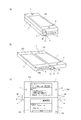
- FIG. 1A is a perspective view showing an external appearance of the mobile phone 100 in a closed state
- FIG. 1B is a perspective view showing an external appearance of the mobile phone 100 in an open state
- FIG. It is a front view which shows the external appearance of an open state.
- the mobile phone 100 is a so-called slide-type terminal in which the first housing 1 and the second housing 2 are relatively movable.
- the housing 1, the second housing 2, and the connection mechanisms 4 and 4 ′ that connect the first housing 1 and the second housing 2 are provided.
- the first casing 1 is provided with a touch panel 110, a speaker 7, and a microphone 8.
- the second casing 2 is provided with a touch panel 120 and an open / close detection sensor 130.
- the open / close detection sensor 130 is a sensor that detects whether the mobile phone 100 is in an open state or a closed state, as will be described later.
- a guide groove 6 is provided on the side surface of the second housing 2 where the coupling mechanism 4 is provided.
- a guide groove is provided on the side surface of the second housing 2 where the coupling mechanism 4 ′ is provided.
- the connecting mechanism 4 includes a connecting piece 5 and pins 30 and 31 for connecting the side surface of the first housing 1 and the side surface of the second housing 2 to each other.
- the connection mechanism 4 ' similarly includes a connection piece 5' and pins 30 'and 31'.
- the pins 30, 30 ' are pivotally supported by the first housing 1, and the pins 31, 31' are engaged with the respective guide grooves. As the pins 31 and 31 ′ slide along the guide grooves, the first housing 1 and the second housing 2 relatively move.
- the mobile phone 100 is connected to the second casing 2 from the closed state where the first casing 1 is overlaid and the touch panel 120 cannot be visually recognized.
- the first casing 1 moves along the surface of the second casing 2 by sliding along the guide grooves 31 ′, and then the pins 30, 30 ′ are respectively centered on the pins 31, 31 ′.
- the surface of the first housing 1 and the surface of the second housing 2 are in an open state in which they are aligned on substantially the same plane. 120 becomes visible.
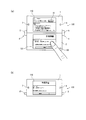
- FIG. 2 is a diagram illustrating a display example of the mobile phone 100 and a user operation example
- FIG. 3 is a diagram illustrating a display example of the mobile phone 100.
- the content of the received mail (hereinafter referred to as “mail screen”) is displayed on the touch panel 110, and a document attached to the received mail (hereinafter referred to as “estimate screen”) is displayed on the touch panel 120.
- “)” Is displayed, indicating that the user is trying to perform an operation of scrolling the estimate screen.
- estimate screen is displayed by selecting the attached file button 10 arranged on the mail screen.
- the estimate screen displayed on the touch panel 110 is a screen obtained by scrolling the estimate screen displayed on the touch panel 120 in FIG. 2A as a result of the scroll operation.
- the touch panels 110 and 120 are visible, but when the mobile phone 100 is deformed from the open state to the closed state, only the touch panel 110 can be viewed.
- the cellular phone 100 automatically determines and displays a screen that the user would want to refer to in the closed state in accordance with the user's operation state on each touch panel immediately before the transformation from the open state to the closed state.
- the user can increase the possibility of continuing to refer to the intended screen without performing an operation for switching the display.
- the mobile phone 100 is placed on the touch panel 110 in FIG. 2B as shown in FIG.
- the displayed estimate screen is continuously displayed on the touch panel 110, and the mail screen displayed on the touch panel 110 in FIG. That is, the mail screen and the estimate screen are displayed on a touch panel different from the touch panel displayed in FIG.
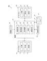
- FIG. 4 is a block diagram showing a functional configuration of main parts of the mobile phone 100.
- the mobile phone 100 includes touch panels 110 and 120, an open / close detection sensor 130, a contact information storage unit 140, a memory 141, and a control unit 150, as shown in FIG.
- the communication unit provided in a normal mobile phone, the speaker 7, the microphone 8 and the like shown in FIG. 1 are not shown.
- the mobile phone 100 includes a processor and a memory, and each function of the control unit 150 is realized by the above-described processor executing a program stored in the above-described memory.
- the touch panel 110 includes a display unit 111, an input unit 112, and an illumination unit 113
- the touch panel 120 includes a display unit 121, an input unit 122, and an illumination unit 123.
- Each display unit includes an LCD (Liquid Crystal Display) and is a circuit that displays an image such as a character or an icon on the LCD in response to an instruction from the control unit 150. It is assumed that the number of pixels (horizontal ⁇ vertical) of each LCD is 800 ⁇ 480 pixels.
- each input unit is a circuit that detects a contact by the user, and sends a coordinate value (x, y) of the contact position to the control unit 150 every unit time (for example, 25 ms) during detection. is there.
- Each input unit is realized by, for example, a capacitive touch sensor.
- Each illumination unit is a backlight that illuminates a corresponding display unit, and is turned on or off according to an instruction from the control unit 150.
- the open / close detection sensor 130 has a function of outputting a signal (hereinafter referred to as “detection signal”) indicating whether the mobile phone 100 is in an open state or a closed state. This is realized by a Hall sensor that detects the magnetic force of the magnet embedded in the magnet.
- the contact information storage unit 140 is information (hereinafter referred to as “panel number”) indicating the touch panel including the coordinate value received from each input unit, the time when the coordinate value is received, and the input unit that is the source of the coordinate value. Is a memory area for storing information (hereinafter referred to as “contact information”).
- the memory 141 is a memory area having two areas m1 and m2 for storing data constituting a screen to be displayed on each display unit (hereinafter referred to as “drawing data”).
- the control unit 150 has a function of controlling the display on each display unit based on the content of the detection signal received from the open / close detection sensor 130, in addition to the function of a general mobile phone. 151, the determination part 152, the display control part 153, the illumination control part 154, and the process execution part 155 are comprised.
- the contact detection unit 151 detects a contact on each touch panel based on the reception of the coordinate value sent from each input unit, and includes the received coordinate value, the time when the coordinate value is received, and the panel number. It has a function of storing information in the contact information storage unit 140.
- the time is obtained using a value obtained at any time from a time measuring unit (not shown) (for example, a time value in units of 1 ms).
- the contact detection unit 151 uses “1” as the panel number and the coordinate value transmission source is the input unit 122. In some cases, “2” is stored as the panel number.
- the determination unit 152 includes contact information including the latest time stored in the contact information storage unit 140 (hereinafter, referred to as “contact information”). Based on “latest contact information”), it has a function of determining whether or not a specific contact has been made.
- the specific contact is the contact made on the touch panel 120 from the time when it was last changed to the open state to the current time, in particular, a predetermined time (for example, “10 seconds”) before the current time. Refers to contact made between the current time and the current time.
- the determination unit 152 manages information indicating whether the mobile phone 100 is in an open state or a closed state (hereinafter referred to as “state information”) on the memory 141, and detects from the open / close detection sensor 130. When the state indicated by the signal changes, this state information is updated so as to indicate the state after the change. In the present embodiment, for example, when the detection signal changes to indicate an open state, the determination unit 152 updates the state information to “0” and changes so that the detection signal indicates a closed state. In this case, the state information is updated to “1”.
- the display control unit 153 manages the association between the two areas m1 and m2 of the memory 141 and the display units 111 and 121, and displays each display based on the association and the state information managed by the determination unit 152. Part display control function How to control the display of each display unit will be described in detail later (see FIG. 5).
- the display control unit 153 updates the association based on the determination that the specific contact is performed by the determination unit 152. That is, for example, when the area m1 and the display unit 111 are associated with each other and the area m2 and the display unit 121 are associated with each other, if it is determined that the specific contact is performed, the display control unit 153 is performed. Updates the area m1 and the display unit 121 so that the area m2 and the display unit 111 are associated with each other.
- the display control unit 153 manages information (hereinafter referred to as “association information”) indicating the association state between each region and each display unit in the memory 141, and as an example, the region m1 and the display unit 111 is “0” when the region m2 and the display unit 121 are associated with each other, “0” when the region m2 is associated with the display unit 121, and the region m2 and the display unit 111 are associated with each other. In this case, “1” is set.
- the illumination control unit 154 has a function of particularly controlling lighting and extinguishing of the illumination unit 123 based on the state information managed by the determination unit 152.
- the process execution unit 155 has a function of specifying the contact position based on the coordinate value and the panel number included in the contact information stored in the contact information storage unit 140, and executing a process corresponding to the contact position.
- the process corresponding to the contact position refers to the object (icon, button) arranged at the position indicated by the coordinate value included in the contact information on the touch panel indicated by the panel number included in the stored contact information. Etc.).
- the process execution unit 155 assumes that the area m1 and the display unit 111 are associated with the area m2 and the display unit 121, respectively, and the object information (arrangement of size, shape, coordinates, etc.). Management is performed for each display unit to be displayed, and based on the information on the object and the association information, it is determined whether the object is arranged at the touched position.
- the region m1 and the display unit 121 are combined with the region m2 and the display unit 111. Therefore, it is necessary to determine whether or not the object is arranged at the touched position with reference to the object information on the display unit 121.
- FIG. 5 is a flowchart showing control processing of the mobile phone 100.
- the control process shown in the figure is started when the power of the mobile phone 100 is turned on, and is ended when the power is turned off, although not particularly shown.
- the display control unit 153 of the control unit 150 displays a standby screen stored in a nonvolatile memory (not shown) provided in the mobile phone 100.
- Each drawing data to be configured is stored in predetermined areas m1 and m2 of the memory 141, and the association information is set to “0”.
- the determination unit 152 determines whether the detection signal output from the open / close detection sensor 130 indicates an open state or a closed state (step S1).
- Step S1 Closed state
- the closed state that is, the state information is set to “1”, and the control unit 150 performs processing from Step S8 described later.
- step S1 open state
- the determination unit 152 updates the state information to indicate the open state, that is, “0”, and the display control unit 153 Since the state information is “0”, the drawing data stored in the area m1 is displayed on the display unit 111, and the drawing data stored in the area m2 is displayed on the display unit 121.
- the lighting control unit 154 Is turned on (step S2). Note that the determination unit 152 obtains the time when the state information is updated to “0” by using a value obtained as needed from a timing unit (not shown).
- the contact detection unit 151 determines whether contact with a finger or the like is detected on any touch panel based on whether coordinate values are received from any input unit (112 or 122) (step S3).
- contact information including the received coordinate value, the time when the coordinate value is received, and the panel number is stored in the contact information storage unit 140.
- the processing execution unit 155 executes processing corresponding to the touched position based on the panel number and the coordinate value included in the contact information stored by the contact detection unit 151, and each drawing data constituting the processing result screen Is stored in each of the areas m1 and m2.
- the display control unit 153 displays the drawing data stored in the area m1 on the display unit 111 and the drawing data stored in the area m2 on the display unit 121 (step S4).
- the process execution unit 155 When the icon is arranged at the position indicated by the coordinate value included in the contact information on the display unit of the touch panel indicated by the panel number included in the stored contact information, the process execution unit 155 The process assigned to the icon is executed, and the display control unit 153 displays the processing result screen on each display unit.
- step S4 When the process of step S4 is completed or no contact is detected in step S3 (step S3: NO), the determination unit 152 determines whether the detection signal from the open / close detection sensor 130 indicates a closed state. (Step S5) When the open state is indicated (Step S5: NO), the process is started again from Step S3.
- step S5 when the closed state is indicated in step S5 (step S5: YES), the determination unit 152 updates the state information to indicate the closed state, that is, “1”, and stores it in the contact information storage unit 140. It is determined whether or not there is a specific contact based on the latest contact information stored (step S6).
- the determination unit 152 has a panel number included in the latest contact information “2”, and the time included in the latest contact information is a time after the time when the last opened state, It is determined that there is a specific contact when it is included between the current time and a predetermined time (10 seconds in this example) before the current time (step S6: YES).
- the determination unit 152 determines that the time included in the latest contact information is not a time after the time when the last open state is set, Alternatively, when the time included in the latest contact information is not included between the predetermined time (10 seconds in this example) before the current time and the current time, it is determined that there is no specific contact (step S6: NO). .
- step S6 When it is determined in step S6 that there is a specific contact (step S6: YES), the display control unit 153 updates the association so that the region m1 and the display unit 121 correspond to the region m2 and the display unit 111, respectively. (Step S7), and the association information is updated to “1”.
- step S6 When the process of step S7 is completed or when it is determined in step S6 that there is no specific contact (step S6: NO), the display control unit 153 is associated with the display unit 111 because the state information is “1”. The drawing data of the area is displayed on the display unit 111, and the display on the display unit 121 is stopped (step S8). At this time, the illumination control unit 154 turns off the illumination unit 123.
- the drawing data stored in the area m2 is displayed. That is, the display data is displayed on the display unit 121 before the process of step S8. The screen that has been displayed is displayed on the display unit 111.
- the drawing data stored in the area m1 is displayed. That is, before the process of step S8, the display unit 111 displays the drawing data. The previously displayed screen continues to be displayed.
- step S3 the contact detection unit 151 determines whether or not contact with a finger or the like has been detected on any touch panel (step S9). If contact is detected (step S9: YES), The contact information is stored in the contact information storage unit 140 in the same manner as in the positive determination (step S3: YES) in step S3.
- the process execution unit 155 executes a process corresponding to the touched position based on the panel number and the coordinate value included in the contact information stored by the contact detection unit 151, and configures the process result screen.
- Drawing data is stored in each area
- processing execution unit 155 and the display control unit 153 do not perform any particular processing when there is no icon or the like at the touched position and there is no corresponding processing, as in step S4.
- step S10 determines whether the detection signal from the open / close detection sensor 130 indicates an open state.
- Step S11 determines whether the detection signal from the open / close detection sensor 130 indicates an open state.
- Step S11: NO the control unit 150 performs the process from Step S9 again.
- Step S11: YES the open state is indicated (Step S11: YES)
- the determining unit 152 As shown in the open state, that is, the state information is updated to “0”, and the control unit 150 performs the processing from step S2 again.
- the determination unit 152 obtains the time when the state information is updated to “0” using a value obtained as needed from a timing unit (not shown).
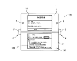
- the mobile phone 100 is in an open state, the user selects the mail icon 11 on the standby screen shown in FIG. 6A, and the mail shown in FIG.
- the mobile phone 100 is transformed into a closed state, and then the mobile phone 100 is opened again. Shall be in a state. It is assumed that the mail application is activated when the mail icon 11 is selected.
- FIG. 6 is a diagram showing a display example of the mobile phone 100.
- the determination unit 152 determines whether the detection signal output from the open / close detection sensor 130 indicates an open state or a closed state (step S ⁇ b> 1). (Step S1: open state), the determination unit 152 updates the state information to “0”, acquires the time at this time, and since the state information is “0”, the display control unit 153 Each drawing data stored in m1 and m2 is displayed on the corresponding display unit (111, 121), and the illumination control unit 154 turns on each illumination unit (step S2).
- the contact detection unit 151 determines whether contact with a finger or the like has been detected on any touch panel (step S3), and in this example, the user selects the mail icon 11 in FIG. The contact is detected (step S3: YES), and the contact detection unit 151 stores the contact information in the contact information storage unit 140.
- the process execution unit 155 is assigned to the mail icon 11 as a process corresponding to the touched position based on the panel number and the coordinate value included in the contact information stored by the contact detection unit 151.
- the mail application activation process is executed, and the display control unit 153 displays the screen of the activated mail application on each display unit as shown in FIG. 6B (step S4).
- the determination unit 152 determines whether the detection signal from the open / close detection sensor 130 indicates a closed state (step S5), and in this example, indicates an open state (step S5: NO).
- the contact detection unit 151 determines whether or not a touch of a finger or the like is detected on any touch panel (step S3), and in this example, the user selects the attached file button 10 in FIG. 6B. Therefore, contact is detected (step S3: YES), and the contact detection unit 151 stores the contact information in the contact information storage unit 140.
- the process execution unit 155 displays the content of the attached file assigned to the attached file button 10 on the display unit 121 as shown in FIG. 2A as the process corresponding to the touched position.
- the display control unit 153 continues to display the mail screen on the display unit 111 and displays the estimate screen on the display unit 121 (step S4).
- the process of displaying the contents of the attached file is a process of starting the corresponding application according to the type of the attached file and displaying the attached file on the application.
- step S4 since the estimate file of the attached file is created by the word processor application, the word processor application is activated and the attached file is displayed on the word processor application.
- the determination unit 152 determines whether the detection signal from the open / close detection sensor 130 indicates a closed state (step S5), and in this example, indicates an open state (step S5: NO).
- the contact detection unit 151 determines whether or not a touch of a finger or the like has been detected on any touch panel (step S3), and in this example, the user performs a scroll operation on the estimate screen, so the contact is not detected. If detected (step S3: YES), the contact detection unit 151 stores the contact information in the contact information storage unit 140.
- the process execution unit 155 executes scroll processing of the estimate screen as a process corresponding to the touched position, and the display control unit 153 continues to display the mail screen on the display unit 111 and displays the display unit.
- the estimate screen after the scroll process is displayed on 121 (step S4).
- the determination unit 152 determines whether the detection signal from the open / close detection sensor 130 indicates a closed state (step S5), and in this example, indicates a closed state (step S5: YES).
- the determination unit 152 updates the state information to “1”, and determines whether or not there is a specific contact based on the latest contact information stored in the contact information storage unit 140.
- the panel number included in the latest contact information is “2”, and here, the time included in the latest contact information is The determination unit 152 determines that there is a specific contact if it is included in the time after the time when it was last opened and included in the current time from a predetermined time (10 seconds in this example) before the current time. (Step S6: YES), the display control unit 153 updates the association so that the region m1 and the display unit 121 correspond to the region m2 and the display unit 111, respectively (Step S7), and sets the association information to “1”. Update to
- step S7 When the process of step S7 is completed, since the state information is “1”, the display control unit 153 draws the drawing data (scroll) stored in the area m2 associated with the display unit 111 as illustrated in FIG. The subsequent estimate screen) is displayed on the display unit 111, and the display on the display unit 121 is stopped (step S8). At this time, the illumination control unit 154 turns off the illumination unit 123.
- the contact detection unit 151 determines whether or not contact with a finger or the like has been detected on any touch panel (step S9), and in this example, no contact is detected (step S9: NO).
- the determination unit 152 determines whether the detection signal from the open / close detection sensor 130 indicates an open state (step S11). In this example, when the open state is indicated (step S11: YES), the determination unit 152 The status information is updated to “0”, and the time at this time is acquired.
- the display control unit 153 continues to display the drawing data (the estimate screen after scrolling) stored in the area m2 associated with the display unit 111 as shown in FIG.
- the drawing data (mail screen) stored in the area m1 associated with the display unit 121 is displayed on the display unit 121, the lighting control unit 154 continues to turn on the lighting unit 113, and turns on the lighting unit 123. (Step S2).
- the mobile terminal according to the present invention has been described based on the embodiment.
- the mobile terminal can be modified as follows, and the present invention is limited to the mobile phone as described in the above-described embodiment. Of course not.
- the screen displayed on the display unit 121 immediately before the deformation is directly displayed on the display unit 111.
- the entire or part of the screen displayed on the display unit 121 may be enlarged or reduced and displayed on the display unit 111, or the screen displayed on the display unit 121 may be displayed.
- a screen reflecting the contents may be displayed on the display unit 111.
- the screen reflecting the contents of the screen displayed on the display unit 121 refers to a screen having a different appearance while maintaining the information amount of the screen displayed on the display unit 121.
- Examples include a screen in which the arrangement of objects constituting the displayed screen is changed, a screen in which the color scheme of the screen displayed on the display unit 121 is changed, and the like.
- the number of pixels of the LCD of each display unit is the same and the shape of the LCD is substantially rectangular.
- the shape may be, for example, a circular shape or other polygonal shapes.
- the mobile phone 100 is again opened without detecting contact on the touch panel 110.
- the case has been described as an example. Therefore, the screens displayed on the display unit 111 of the touch panel 110 in FIG. 2B and the display unit 111 of the touch panel 110 in FIG. 3 are the same, and the display unit 111 of the touch panel 110 in FIG. It has been described that the screens displayed on the display unit 121 of the touch panel 120 in FIG. 3 are the same.
- step S9 in FIG. 5: YES the process execution unit 155 executes a process corresponding to the touched position, and displays a process result screen. 2 is stored in each of the areas m1 and m2, so that the screens displayed on the display unit 111 of the touch panel 110 in FIG. 2B and the display unit 111 of the touch panel 110 in FIG.
- the display control unit 153 updates the association between the display units and the areas m1 and m2, and the mobile phone 100
- the association is not updated even when the telephone 100 is changed to the open state again, the association is not updated, that is, before the mobile phone 100 is changed from the open state to the closed state. It is also possible to update so that the correspondence is established and display based on the updated association.
- the above association may be restored only when the elapsed time since the deformation into the closed state is within a predetermined time (for example, within several minutes).
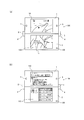
- the mobile phone 100 according to the embodiment has been described as a slide type mobile phone, mobile phones having other appearances, for example, as shown in FIGS. 7A to 7C A foldable mobile phone 200 may also be used.
- the mobile phone 200 is configured such that a first casing 201 provided with a touch panel 210 and a second casing 202 provided with a touch panel 220 and an opening / closing detection sensor 230 can be opened and closed.
- the mobile phone 200 is opened from the open state where the first casing 201 and the second casing 202 are opened and the respective touch panels can be visually recognized. ), The first housing 201 is rotated by 180 ° with respect to the second housing, and then the first housing 201 and the second housing are closed to each other so that the second housing 202 is provided.
- the shape of the touch panel 220 can be changed to a closed state in which the touch panel 220 is hidden behind the first casing 201 and only the touch panel 210 provided in the first casing 201 is visible.
- FIG. 7A In the state of FIG. 7A, immediately after the user operates on the touch panel 220, as shown in FIGS. 7B and 7C, the mobile phone 200 is deformed to the closed state, so that FIG. As shown in c), even when the mobile phone 200 is in the closed state, the screen displayed on the touch panel 220 is displayed on the touch panel 210 before the deformation, and the user can view the screen displayed on the touch panel 220. become able to.
- each touch panel has been described as being realized by a capacitive touch sensor.
- this capacitive touch sensor a large number of electrode patterns are made of plastic, glass, or the like.
- a projection type that is formed on a substrate and discriminates by measuring the ratio of the amount of current by a plurality of electrode patterns in the vicinity of the contact point, and has a conductive film and a substrate, and electrodes are formed at the corners of the substrate.
- An appropriate one can be used, such as a surface type that forms a uniform electric field by a conductive film and measures the ratio of the current amount of the terminal at the corner by contact with a finger or the like to determine the contact position.
- each touch panel is not limited to being realized by a capacitive touch sensor, but an electromagnetic induction method using a dedicated pen such as an electronic pen, or a matrix switch method including a two-layer transparent electrode Or, a voltage is applied to one of the two resistance films, and a resistance film method for detecting a voltage according to the position operated on the other resistance film, or a rebound of the vibration wave is detected by a voltage change of the piezoelectric element, It is realized by the surface acoustic wave method that detects the touch of the finger, the infrared method that detects the position where the finger etc. touched by the shielded infrared light, the optical sensor method that detects the contact position by incorporating the optical sensor in the screen, etc. May be.
- the mobile phone 100 has been described as the touch panel 110 and the touch panel 120 are disposed on the upper and lower sides on the substantially same plane when viewed from the user in a normal use state, You may be made to do.
- the mobile phone 100 has been described as the touch panel 110 and the touch panel 120 are arranged on substantially the same plane in the open state as illustrated in FIG. Any arrangement may be used as long as each touch panel is visible.
- the surface including the touch panel 110 of the first housing 1 and the surface including the touch panel 120 of the second housing 2 may be arranged substantially parallel to each other. Between the surface including the touch panel 110 and the surface including the touch panel 120 of the second housing 2, the touch panel 110 may be disposed so that an angle is formed so that each touch panel can be visually recognized.
- the predetermined time used for determining whether or not there is a specific contact has been described as 10 seconds. However, this is an example, and a shorter time (for example, 5 seconds) may be used. It may be a long time (for example, 1 minute), or the user may be able to set an arbitrary value.
- the user is caused to perform an operation on the touch panel 120 and the subsequent deformation to the closed state, and the predetermined time is set based on the result. You may do it.
- the reason why the predetermined time is used to determine whether or not there is a specific contact is that the touch panel 120 is used in the past (for example, several days ago) from the time when the mobile phone 100 is deformed from the open state to the closed state. This is because even if the operation is performed, it is difficult for the user to continue to refer to the screen displayed on the touch panel 120 after the transformation to the closed state. Therefore, it is desirable to set the predetermined time as long as it does not contradict this purpose.
- this predetermined time may not be used for determining whether or not there is a specific contact, or whether or not the user uses it may be set.
- this predetermined time is not used, in step S6 of FIG. 5, the panel number included in the latest contact information is “2”, and the time included in the latest contact information is the previous time.
- the time is after the time when the open state is reached, it is determined that the specific contact has occurred.
- Each component described in the embodiment realizes its function by cooperating with a processor included in the mobile phone.
- a program for causing a CPU (Central Processing Unit) to execute processing (see FIG. 5) for input from each touch panel described in the embodiment is recorded on a recording medium or via various communication paths, etc. It can also be distributed and distributed.
- a recording medium includes an IC card, an optical disk, a flexible disk, a ROM, a flash memory, and the like.
- the distributed and distributed program is used by being stored in a memory or the like that can be read by a CPU in the device, and each function of the mobile phone described in the embodiment is performed by the CPU executing the program. Realized.
- the mail screen and the estimate screen were used as an example of the screen displayed on the touch panel 110 and the touch panel 120, this invention is limited to the case where such a screen is displayed. Instead, any screen can be used as the display screen within the scope of the present invention.
- the screen example displayed on the touch panel 110 and the touch panel 120 and replaced is a screen by separate applications, that is, a screen by a mail application and a word processor application, but the present invention is in such a case.
- the display screens displayed on the touch panel 110 and the touch panel 120 may be display screens by one application.
- the touch panel 110 and the touch panel 120 may display a screen by one image display application (for example, a map display application).
- the displayed touch panel is switched by the processing of the above embodiment on the display screens on the touch panel 110 and the touch panel 120 by this one image display application.
- a mobile terminal is a mobile terminal that includes a plurality of casings and is configured such that the relative position of each casing can be changed, and is disposed in the first casing.
- the display unit can be viewed from a display unit that displays an image, a touch panel that displays an image and detects contact, and an open state in which the touch panel is visible.
- a detection unit that detects that the touch panel has been changed to a closed state in which at least a part of the touch panel is covered by the first housing, and when the detection unit performs detection, A determination unit that determines whether or not contact on the touch panel is detected between the time when the detection unit is detected and the determination unit makes a positive determination, before the detection by the detection unit Displayed on the touch panel Characterized in that the image had a control unit for performing continuous display process for displaying on the display unit.
- the touch panel when contact is detected on the touch panel during the period from the previous opening to the closing, the touch panel The displayed image is displayed on a display portion that is visible even in the closed state.
- the said portable terminal is further provided with the touch sensor which detects the contact on the display surface of the said display part, and the said control part is on the said touch panel when the contact on the said touch panel is detected.
- the continuous display processing is performed only when contact on the touch sensor is not detected after detection of contact on the touch sensor and before detection of the change to the closed state by the detection unit. It is good also as performing.
- the portable terminal which concerns on one Embodiment of this invention, when the latest contact detected until it will be in a closed state from the time of being in an open state last time is a contact on a touch panel. Only the image displayed on the touch panel is displayed on the display unit.
- this portable terminal changes from the open state to the closed state, it is possible to further increase the possibility of displaying the screen intended by the user on the display unit that is visible even in the closed state.
- the said touch panel is provided with the illumination part which irradiates light to the display area which displays an image,
- the said control part further detects that the said detection part changed to the said closed state. When performed, the irradiation by the irradiation unit may be stopped.
- the portable terminal which concerns on one Embodiment of this invention, when the change from an open state to a closed state is detected, the display of the touch panel at least partially covered by the 1st housing
- the detection unit further detects a change from the closed state to the open state, and the control unit further detects the detection unit from the closed state to the open state.
- the image displayed on the display unit immediately before the continuous display process is displayed on the touch panel, and the irradiation unit
- the irradiation by the irradiation unit may be restarted.
- the portable terminal which concerns on one Embodiment of this invention, when the change from a closed state to an open state is detected, the continuous display process which makes the display part display the image currently displayed on the touch panel is made.
- the display unit and the touch panel can be used effectively.
- the portable terminal when a change to the open state is detected, the portable terminal continuously displays the image displayed on the display unit by the continuous display process on the display unit. Compared with the case where the image that has been displayed is displayed again on the touch panel, it is possible to realize a display without a sense of incongruity.
- control part is good also as performing the said continuous display process, only when the contact on the said touch panel is detected by the said detection from the predetermined time before the detection by the said detection part.
- this portable terminal after operating on a touch panel by setting predetermined time (for example, about several minutes), this portable terminal remains in an open state, for example, It is possible to prevent the continuous display process from being performed when it is left for several hours and then closed. This is because it is difficult for the user to continue to refer to the screen of the touch panel when the user operates the touch panel and then closes it after many hours.
- the display unit and the touch sensor and the touch panel of the mobile terminal according to the present invention correspond to the touch panels 110 and 120 of the mobile phone 100 according to the embodiment, and the detection unit of the mobile terminal according to the present invention It corresponds to the open / close detection sensor 130 of the mobile phone 100 according to the embodiment, and the determination unit and the control unit of the mobile terminal according to the present invention correspond to the control unit 150 of the mobile phone 100 according to the embodiment.
- the display control method according to the present invention is realized by, for example, the mobile phone 100 shown in the embodiment (in particular, refer to the control processing procedure shown in FIG. 5).
- the portable terminal according to the present invention is used when a user performs an operation using a touch panel.
Landscapes
- Engineering & Computer Science (AREA)
- Theoretical Computer Science (AREA)
- General Engineering & Computer Science (AREA)
- Physics & Mathematics (AREA)
- Computer Hardware Design (AREA)
- General Physics & Mathematics (AREA)
- Human Computer Interaction (AREA)
- Mathematical Physics (AREA)
- Signal Processing (AREA)
- Telephone Function (AREA)
- Digital Computer Display Output (AREA)
- Studio Devices (AREA)
- User Interface Of Digital Computer (AREA)
- Telephone Set Structure (AREA)
Priority Applications (1)
| Application Number | Priority Date | Filing Date | Title |
|---|---|---|---|
| US13/637,637 US9191472B2 (en) | 2010-03-26 | 2011-03-24 | Portable terminal, display control program and display control method |
Applications Claiming Priority (2)
| Application Number | Priority Date | Filing Date | Title |
|---|---|---|---|
| JP2010-072546 | 2010-03-26 | ||
| JP2010072546A JP2011205532A (ja) | 2010-03-26 | 2010-03-26 | 携帯端末及び表示制御プログラム |
Publications (1)
| Publication Number | Publication Date |
|---|---|
| WO2011118217A1 true WO2011118217A1 (ja) | 2011-09-29 |
Family
ID=44672795
Family Applications (1)
| Application Number | Title | Priority Date | Filing Date |
|---|---|---|---|
| PCT/JP2011/001734 Ceased WO2011118217A1 (ja) | 2010-03-26 | 2011-03-24 | 携帯端末、表示制御プログラム及び表示制御方法 |
Country Status (3)
| Country | Link |
|---|---|
| US (1) | US9191472B2 (https=) |
| JP (1) | JP2011205532A (https=) |
| WO (1) | WO2011118217A1 (https=) |
Cited By (4)
| Publication number | Priority date | Publication date | Assignee | Title |
|---|---|---|---|---|
| JP2014512602A (ja) * | 2011-11-30 | 2014-05-22 | ネオノード インコーポレイテッド | 光学式指ジェスチャユーザインタフェース |
| EP2681650A4 (en) * | 2011-02-28 | 2015-06-03 | Blackberry Ltd | ELECTRONIC DEVICE AND METHOD FOR DISPLAYING THE INFORMATION AS A RESPONSE TO A GESTURE |
| JP5966059B1 (ja) * | 2015-06-19 | 2016-08-10 | レノボ・シンガポール・プライベート・リミテッド | 携帯型情報処理装置、その画面切り替え方法、及びコンピュータが実行可能なプログラム |
| CN111831196A (zh) * | 2019-04-17 | 2020-10-27 | 成都鼎桥通信技术有限公司 | 折叠屏幕的控制方法、终端设备以及存储介质 |
Families Citing this family (10)
| Publication number | Priority date | Publication date | Assignee | Title |
|---|---|---|---|---|
| WO2013073197A1 (ja) * | 2011-11-18 | 2013-05-23 | 株式会社ニコン | 携帯型電子情報端末機、撮像装置及び撮像制御プログラム |
| JPWO2013111603A1 (ja) * | 2012-01-27 | 2015-05-11 | パナソニック インテレクチュアル プロパティ コーポレーション オブアメリカPanasonic Intellectual Property Corporation of America | 情報処理装置、情報処理方法、および情報処理プログラム |
| EP2942942A4 (en) * | 2013-03-15 | 2016-08-31 | Sony Corp | Image processing apparatus and method for determining the GUI structure of the image processing apparatus |
| JP2015005786A (ja) * | 2013-05-21 | 2015-01-08 | 昌輝 戸谷 | 画像表示装置 |
| US9727295B2 (en) * | 2013-12-17 | 2017-08-08 | Lenovo (Singapore) Pte. Ltd. | Extendable display mechanism |
| US10474409B2 (en) * | 2014-09-19 | 2019-11-12 | Lenovo (Beijing) Co., Ltd. | Response control method and electronic device |
| JP6246861B1 (ja) * | 2016-06-27 | 2017-12-13 | レノボ・シンガポール・プライベート・リミテッド | 電子機器 |
| CN109656494A (zh) * | 2017-10-12 | 2019-04-19 | 阿里巴巴集团控股有限公司 | 拼接屏幕中显示内容的管理方法 |
| JP7183597B2 (ja) * | 2018-07-12 | 2022-12-06 | 京セラドキュメントソリューションズ株式会社 | プレビュー画像表示装置及びプレビュー画像表示プログラム |
| WO2021075610A1 (ko) * | 2019-10-18 | 2021-04-22 | 엘지전자 주식회사 | 이동 단말기 |
Citations (2)
| Publication number | Priority date | Publication date | Assignee | Title |
|---|---|---|---|---|
| WO2003077097A1 (en) * | 2002-03-08 | 2003-09-18 | Mitsubishi Denki Kabushiki Kaisha | Mobile communication device, display control method of mobile communication device, and program therefor |
| JP2009164794A (ja) * | 2007-12-28 | 2009-07-23 | Kyocera Corp | 携帯通信端末 |
Family Cites Families (4)
| Publication number | Priority date | Publication date | Assignee | Title |
|---|---|---|---|---|
| JP3957693B2 (ja) | 2004-03-08 | 2007-08-15 | 埼玉日本電気株式会社 | マルチウィンドウ表示型携帯端末装置 |
| US20060082518A1 (en) * | 2004-10-19 | 2006-04-20 | Pranil Ram | Multiple monitor display apparatus |
| EP2309369B1 (en) * | 2008-07-25 | 2016-09-28 | NEC Corporation | Information processing device, information processing program, and display control method |
| JP5557316B2 (ja) * | 2010-05-07 | 2014-07-23 | Necカシオモバイルコミュニケーションズ株式会社 | 情報処理装置、情報生成方法及びプログラム |
-
2010
- 2010-03-26 JP JP2010072546A patent/JP2011205532A/ja active Pending
-
2011
- 2011-03-24 US US13/637,637 patent/US9191472B2/en not_active Expired - Fee Related
- 2011-03-24 WO PCT/JP2011/001734 patent/WO2011118217A1/ja not_active Ceased
Patent Citations (2)
| Publication number | Priority date | Publication date | Assignee | Title |
|---|---|---|---|---|
| WO2003077097A1 (en) * | 2002-03-08 | 2003-09-18 | Mitsubishi Denki Kabushiki Kaisha | Mobile communication device, display control method of mobile communication device, and program therefor |
| JP2009164794A (ja) * | 2007-12-28 | 2009-07-23 | Kyocera Corp | 携帯通信端末 |
Cited By (6)
| Publication number | Priority date | Publication date | Assignee | Title |
|---|---|---|---|---|
| EP2681650A4 (en) * | 2011-02-28 | 2015-06-03 | Blackberry Ltd | ELECTRONIC DEVICE AND METHOD FOR DISPLAYING THE INFORMATION AS A RESPONSE TO A GESTURE |
| JP2014512602A (ja) * | 2011-11-30 | 2014-05-22 | ネオノード インコーポレイテッド | 光学式指ジェスチャユーザインタフェース |
| JP5966059B1 (ja) * | 2015-06-19 | 2016-08-10 | レノボ・シンガポール・プライベート・リミテッド | 携帯型情報処理装置、その画面切り替え方法、及びコンピュータが実行可能なプログラム |
| US10884690B2 (en) | 2015-06-19 | 2021-01-05 | Lenovo (Singapore) Pte. Ltd. | Dual screen device having power state indicators |
| CN111831196A (zh) * | 2019-04-17 | 2020-10-27 | 成都鼎桥通信技术有限公司 | 折叠屏幕的控制方法、终端设备以及存储介质 |
| CN111831196B (zh) * | 2019-04-17 | 2022-01-25 | 成都鼎桥通信技术有限公司 | 折叠屏幕的控制方法、终端设备以及存储介质 |
Also Published As
| Publication number | Publication date |
|---|---|
| JP2011205532A (ja) | 2011-10-13 |
| US9191472B2 (en) | 2015-11-17 |
| US20130021284A1 (en) | 2013-01-24 |
Similar Documents
| Publication | Publication Date | Title |
|---|---|---|
| WO2011118217A1 (ja) | 携帯端末、表示制御プログラム及び表示制御方法 | |
| JP5495814B2 (ja) | 携帯端末及び表示制御プログラム | |
| KR102859606B1 (ko) | 어플리케이션의 실행 화면을 제공하기 위한 전자 장치 및 그 동작 방법 | |
| JP5351006B2 (ja) | 携帯端末及び表示制御プログラム | |
| KR20250171243A (ko) | 전자 장치 및 전자 장치의 디스플레이 제어 방법 | |
| JP5813353B2 (ja) | 携帯端末、表示装置、輝度制御方法及び輝度制御プログラム | |
| JP5722024B2 (ja) | 携帯端末、輝度制御方法及びプログラム | |
| KR102859432B1 (ko) | 전자 장치 및 전자 장치의 디스플레이 제어 방법 | |
| JP5473708B2 (ja) | 携帯端末及び表示制御プログラム | |
| KR20140134020A (ko) | 커버장치를 구비하는 휴대용 단말기 | |
| CN107037659A (zh) | 一种柔光灯控制方法及移动终端 | |
| US20180284970A1 (en) | Mobile electronic device, control method, and control medium | |
| CN106547358A (zh) | 一种终端时间信息的显示方法及终端 | |
| JP5754770B2 (ja) | 携帯端末装置、プログラムおよび表示方法 | |
| JP5727310B2 (ja) | 携帯端末、輝度制御方法及びプログラム | |
| JP2012073721A (ja) | 携帯端末、プログラム及び表示制御方法 | |
| CN107517338B (zh) | 电子设备背壳、电子设备及拍摄方法 | |
| JP2013074408A (ja) | 携帯端末、表示制御方法及びプログラム | |
| JP5922497B2 (ja) | 携帯端末、表示制御方法及びプログラム | |
| JP2012182761A (ja) | 携帯端末装置 | |
| JP5717813B2 (ja) | 携帯端末 | |
| JP5788068B2 (ja) | 携帯端末 |
Legal Events
| Date | Code | Title | Description |
|---|---|---|---|
| 121 | Ep: the epo has been informed by wipo that ep was designated in this application |
Ref document number: 11759026 Country of ref document: EP Kind code of ref document: A1 |
|
| NENP | Non-entry into the national phase |
Ref country code: DE |
|
| WWE | Wipo information: entry into national phase |
Ref document number: 13637637 Country of ref document: US |
|
| 122 | Ep: pct application non-entry in european phase |
Ref document number: 11759026 Country of ref document: EP Kind code of ref document: A1 |