WO2011114907A1 - レーザシステム - Google Patents
レーザシステム Download PDFInfo
- Publication number
- WO2011114907A1 WO2011114907A1 PCT/JP2011/055016 JP2011055016W WO2011114907A1 WO 2011114907 A1 WO2011114907 A1 WO 2011114907A1 JP 2011055016 W JP2011055016 W JP 2011055016W WO 2011114907 A1 WO2011114907 A1 WO 2011114907A1
- Authority
- WO
- WIPO (PCT)
- Prior art keywords
- laser
- wavelength
- heater
- intensity
- light
- Prior art date
Links
- 238000001514 detection method Methods 0.000 claims abstract description 43
- 230000001360 synchronised effect Effects 0.000 claims abstract description 10
- 238000005070 sampling Methods 0.000 claims description 14
- 238000003860 storage Methods 0.000 claims description 11
- 238000010586 diagram Methods 0.000 description 16
- 230000008859 change Effects 0.000 description 11
- 239000004065 semiconductor Substances 0.000 description 10
- 238000000034 method Methods 0.000 description 8
- 230000003287 optical effect Effects 0.000 description 8
- 238000006243 chemical reaction Methods 0.000 description 6
- 238000005253 cladding Methods 0.000 description 5
- 239000002096 quantum dot Substances 0.000 description 5
- 229910001218 Gallium arsenide Inorganic materials 0.000 description 4
- 230000007423 decrease Effects 0.000 description 4
- 230000008569 process Effects 0.000 description 4
- 230000008901 benefit Effects 0.000 description 3
- 238000004519 manufacturing process Methods 0.000 description 3
- 239000000758 substrate Substances 0.000 description 3
- 230000002159 abnormal effect Effects 0.000 description 2
- 238000013459 approach Methods 0.000 description 2
- 229910000673 Indium arsenide Inorganic materials 0.000 description 1
- VYPSYNLAJGMNEJ-UHFFFAOYSA-N Silicium dioxide Chemical compound O=[Si]=O VYPSYNLAJGMNEJ-UHFFFAOYSA-N 0.000 description 1
- 230000003321 amplification Effects 0.000 description 1
- RPQDHPTXJYYUPQ-UHFFFAOYSA-N indium arsenide Chemical compound [In]#[As] RPQDHPTXJYYUPQ-UHFFFAOYSA-N 0.000 description 1
- GQYHUHYESMUTHG-UHFFFAOYSA-N lithium niobate Chemical compound [Li+].[O-][Nb](=O)=O GQYHUHYESMUTHG-UHFFFAOYSA-N 0.000 description 1
- 238000012986 modification Methods 0.000 description 1
- 230000004048 modification Effects 0.000 description 1
- 238000003199 nucleic acid amplification method Methods 0.000 description 1
- 230000004044 response Effects 0.000 description 1
- 229910052814 silicon oxide Inorganic materials 0.000 description 1
- 239000007787 solid Substances 0.000 description 1
Images


Classifications
-
- H—ELECTRICITY
- H01—ELECTRIC ELEMENTS
- H01S—DEVICES USING THE PROCESS OF LIGHT AMPLIFICATION BY STIMULATED EMISSION OF RADIATION [LASER] TO AMPLIFY OR GENERATE LIGHT; DEVICES USING STIMULATED EMISSION OF ELECTROMAGNETIC RADIATION IN WAVE RANGES OTHER THAN OPTICAL
- H01S5/00—Semiconductor lasers
- H01S5/06—Arrangements for controlling the laser output parameters, e.g. by operating on the active medium
- H01S5/068—Stabilisation of laser output parameters
- H01S5/06804—Stabilisation of laser output parameters by monitoring an external parameter, e.g. temperature
-
- H—ELECTRICITY
- H01—ELECTRIC ELEMENTS
- H01S—DEVICES USING THE PROCESS OF LIGHT AMPLIFICATION BY STIMULATED EMISSION OF RADIATION [LASER] TO AMPLIFY OR GENERATE LIGHT; DEVICES USING STIMULATED EMISSION OF ELECTROMAGNETIC RADIATION IN WAVE RANGES OTHER THAN OPTICAL
- H01S5/00—Semiconductor lasers
- H01S5/06—Arrangements for controlling the laser output parameters, e.g. by operating on the active medium
- H01S5/062—Arrangements for controlling the laser output parameters, e.g. by operating on the active medium by varying the potential of the electrodes
- H01S5/0625—Arrangements for controlling the laser output parameters, e.g. by operating on the active medium by varying the potential of the electrodes in multi-section lasers
- H01S5/06255—Controlling the frequency of the radiation
- H01S5/06258—Controlling the frequency of the radiation with DFB-structure
-
- H—ELECTRICITY
- H01—ELECTRIC ELEMENTS
- H01S—DEVICES USING THE PROCESS OF LIGHT AMPLIFICATION BY STIMULATED EMISSION OF RADIATION [LASER] TO AMPLIFY OR GENERATE LIGHT; DEVICES USING STIMULATED EMISSION OF ELECTROMAGNETIC RADIATION IN WAVE RANGES OTHER THAN OPTICAL
- H01S5/00—Semiconductor lasers
- H01S5/005—Optical components external to the laser cavity, specially adapted therefor, e.g. for homogenisation or merging of the beams or for manipulating laser pulses, e.g. pulse shaping
- H01S5/0092—Optical components external to the laser cavity, specially adapted therefor, e.g. for homogenisation or merging of the beams or for manipulating laser pulses, e.g. pulse shaping for nonlinear frequency conversion, e.g. second harmonic generation [SHG] or sum- or difference-frequency generation outside the laser cavity
-
- H—ELECTRICITY
- H01—ELECTRIC ELEMENTS
- H01S—DEVICES USING THE PROCESS OF LIGHT AMPLIFICATION BY STIMULATED EMISSION OF RADIATION [LASER] TO AMPLIFY OR GENERATE LIGHT; DEVICES USING STIMULATED EMISSION OF ELECTROMAGNETIC RADIATION IN WAVE RANGES OTHER THAN OPTICAL
- H01S5/00—Semiconductor lasers
- H01S5/02—Structural details or components not essential to laser action
- H01S5/026—Monolithically integrated components, e.g. waveguides, monitoring photo-detectors, drivers
- H01S5/0265—Intensity modulators
-
- H—ELECTRICITY
- H01—ELECTRIC ELEMENTS
- H01S—DEVICES USING THE PROCESS OF LIGHT AMPLIFICATION BY STIMULATED EMISSION OF RADIATION [LASER] TO AMPLIFY OR GENERATE LIGHT; DEVICES USING STIMULATED EMISSION OF ELECTROMAGNETIC RADIATION IN WAVE RANGES OTHER THAN OPTICAL
- H01S5/00—Semiconductor lasers
- H01S5/06—Arrangements for controlling the laser output parameters, e.g. by operating on the active medium
- H01S5/068—Stabilisation of laser output parameters
- H01S5/0683—Stabilisation of laser output parameters by monitoring the optical output parameters
- H01S5/06832—Stabilising during amplitude modulation
-
- H—ELECTRICITY
- H01—ELECTRIC ELEMENTS
- H01S—DEVICES USING THE PROCESS OF LIGHT AMPLIFICATION BY STIMULATED EMISSION OF RADIATION [LASER] TO AMPLIFY OR GENERATE LIGHT; DEVICES USING STIMULATED EMISSION OF ELECTROMAGNETIC RADIATION IN WAVE RANGES OTHER THAN OPTICAL
- H01S5/00—Semiconductor lasers
- H01S5/06—Arrangements for controlling the laser output parameters, e.g. by operating on the active medium
- H01S5/068—Stabilisation of laser output parameters
- H01S5/0683—Stabilisation of laser output parameters by monitoring the optical output parameters
- H01S5/0687—Stabilising the frequency of the laser
Definitions
- the present invention relates to a laser system, and more particularly to a laser system that emits harmonic light of a laser beam.
- semiconductor lasers are used in inexpensive laser systems.
- semiconductor lasers have light in a wavelength band that is difficult to oscillate (for example, green light). Therefore, a method of emitting light in a wavelength band that is difficult to oscillate with a semiconductor laser using a DPSS (Diode Pumped Solid State Laser) method is known.
- DPSS Dynamic Switched Solid State Laser
- Patent Document 1 a laser system that emits laser light emitted from a semiconductor laser by converting it into harmonic light with a nonlinear optical element has been proposed (for example, Patent Document 1).
- the allowable wavelength range is narrowed.
- the semiconductor laser and the nonlinear optical element have different wavelength temperature coefficients. Further, the semiconductor laser and the nonlinear optical element have variations in wavelength characteristics for each individual element. For this reason, for example, when the temperature of the laser module on which the semiconductor laser and the nonlinear optical element are mounted changes, it is not easy to adjust the wavelength of the laser light within a wavelength range that can be converted with high efficiency.
- the temperature of the semiconductor laser may change locally or the characteristics of the semiconductor laser itself may change. In this case, it is difficult to adjust the wavelength of the laser light within a wavelength range that can be converted with high efficiency based on the temperature of the laser module, and the intensity of the harmonic light may decrease.
- the present invention has been made in view of the above problems, and an object of the present invention is to provide a laser system capable of stably emitting harmonic light.
- the present invention provides a laser module including a laser that oscillates laser light, a heater that adjusts the temperature of the laser, and a harmonic generation element that converts the laser light into harmonic light of the laser light, and the laser light
- the detection signal synchronized with the modulation signal used for the modulation is obtained from the intensity of the harmonic light, and the magnitude of the heater current injected into the heater is reduced so that the amplitude of the detection signal is reduced.
- the wavelength of a laser beam can be controlled in the wavelength range which can be converted with a harmonic production
- control unit controls the magnitude of the heater current so that an absolute value of a difference between the detection signals corresponding to the maximum time and the minimum time of the modulation signal is small. It can be set as the structure which makes the amplitude of a signal small.
- the control unit may modulate the intensity of the laser light and modulate the wavelength of the laser light at a frequency higher than the frequency of intensity modulation of the laser light.
- the wavelength of the laser light can be controlled within a wavelength range that can be converted by the harmonic generation element without being affected by the image. Further, the wavelength of the laser light can be quickly controlled within a wavelength range that can be converted by the harmonic generation element, and a normal output state of the harmonic light can be obtained earlier.
- control unit when the intensity modulation of the laser beam is digitally modulated, the control unit may be configured to modulate the wavelength of the laser beam at a frequency higher than the sampling frequency in the digital modulation.
- control unit may be configured to digitally modulate the intensity of the laser beam and modulate the wavelength of the laser beam using the modulation signal synchronized with the sampling in the digital modulation. According to this configuration, a more appropriate detection signal can be obtained.
- control unit may modulate the intensity of the laser light and modulate the wavelength of the laser light at a frequency lower than the frequency of intensity modulation of the laser light. According to this configuration, even when used in, for example, a laser display, the wavelength of the laser light can be within a wavelength range that can be converted by the harmonic generation element without being affected by the image.
- the control unit does not control the magnitude of the heater current injected into the heater so that the amplitude of the detection signal is small when the intensity of the intensity-modulated laser light is smaller than a predetermined threshold value. It can be configured. According to this structure, it can suppress adjusting the wavelength of a laser beam outside the wavelength range which can be converted with a harmonic production
- control unit controls the magnitude of the heater current injected into the heater so that the amplitude of the detection signal becomes small while the magnitude of the drive current for driving the laser is fixed. be able to. According to this configuration, control for reducing the amplitude of the detection signal can be facilitated.
- the storage unit stores a table in which the temperature of the laser module and the heater power input to the heater are associated with each other, and the control unit periodically decreases the amplitude of the detection signal. Based on the controlled heater current, new heater power is written to the table, and when the laser system is turned on, the heater current is injected into the heater with reference to the table. be able to. According to this configuration, when the power of the laser system is turned on, the wavelength of the laser light can be easily and quickly adjusted within the wavelength range that can be converted by the harmonic generation element.
- the control unit generates an error when the difference between the initial value of the heater power previously written in the table and the value of the heater power newly written in the table exceeds a predetermined threshold. It can be set as the structure which outputs. According to this configuration, it is possible to discriminate and eliminate a laser module whose characteristics have deteriorated.
- the wavelength of the laser light can be within a wavelength range that can be converted by the harmonic generation element, and the harmonic light can be stably emitted from the harmonic generation element.
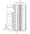
- FIG. 1 is a block diagram illustrating an example of a laser system according to the first embodiment.
- FIG. 2 is a schematic cross-sectional view showing an example of a DFB laser and an SOA.
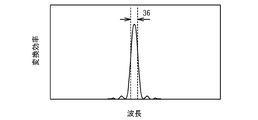
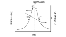
- FIG. 3 is a schematic diagram for explaining the wavelength of the laser beam and the conversion efficiency of the harmonic generation element.
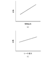
- 4A is a schematic diagram for explaining the relationship between the wavelength of the laser beam and the drive current
- FIG. 4B is a schematic diagram for explaining the relationship between the wavelength of the laser beam and the heater power. is there.
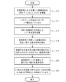
- FIG. 5 is a flowchart illustrating an example of control by the control unit of the laser system according to the first embodiment.
- FIG. 6 is a schematic diagram illustrating an example of a modulation signal and a detection signal.
- FIG. 7 is a schematic diagram showing an example of the relationship between the wavelength of the laser beam and the intensity of the harmonic light and the wavelength of the laser beam and the error signal.
- FIG. 8A is a schematic diagram showing an example of the table in the initial state
- FIG. 8B is a schematic diagram showing an example of the updated table.
- FIG. 9 is a schematic diagram illustrating an example of a signal of laser light that has been subjected to digital intensity modulation.
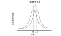
- FIG. 10 is a schematic diagram showing an example of the relationship between the wavelength of the laser beam and the intensity of the harmonic light at the beginning of use of the laser system, and an example of the relationship between the wavelength of the laser beam and the intensity of the harmonic light when the table is updated.
- FIG. 1 is a block diagram illustrating an example of a laser system according to the first embodiment.
- the laser system 100 includes a laser module 10, a control unit 40, an infrared light cut filter 42, a beam splitter 44, a photodetector 46, a storage unit 48,
- the laser module 10 includes a DFB (distributed feedback) laser 12, a heater 14, an optical semiconductor amplifier (SOA) 16, a harmonic generation element 18, a temperature sensor 20, and a lens 22.
- the SOA 16 and the harmonic generation element 18 are optically coupled via the lens 22, and the laser light 24 emitted from the SOA 16 is incident on the harmonic generation element 18.
- DFB distributed feedback
- SOA optical semiconductor amplifier
- the DFB laser 12 has a corrugation and oscillates a single wavelength laser beam 24, and oscillates a laser beam 24 having a wavelength of 1064 nm, for example.
- the DFB laser 12 operates when the drive current 26 is injected by the control unit 40 and oscillates the laser light 24.
- the heater 14 adjusts the temperature of the DFB laser 12 when the heater current 28 is injected by the controller 40.
- the SOA 16 modulates the intensity of the laser light 24 when the voltage 30 is applied by the control unit 40.
- the SOA 16 changes the intensity of the laser beam 24, but does not change the wavelength of the laser beam 24.
- the DFB laser 12 and the SOA 16 are formed on the same chip, and the optical axes of the DFB laser 12 and the SOA 16 are the same.
- the temperature sensor 20 monitors the temperature of the laser module 10 and outputs a temperature monitor value 32 to the control unit 40.
- the harmonic generation element 18 is a non-linear optical element, and converts the incident laser light 24 into the harmonic light 34.
- the harmonic generation element 18 is, for example, PPLN (Periodically Poled Lithium Niobate), and emits harmonic light 34 having a wavelength of, for example, 532 nm, which is the second harmonic light of the laser light 24.
- the infrared light cut filter 42 blocks infrared light out of the light emitted from the harmonic generation element 18 and allows only the harmonic light 34 to pass therethrough.
- the beam splitter 44 branches a part of the harmonic light 34 and makes it incident on the photodetector 46.
- the photodetector 46 monitors the intensity of the harmonic light 34 and outputs a light output monitor signal 49 to the control unit 40.
- the storage unit 48 is, for example, a non-volatile memory, and stores a table in which the temperature of the laser module 10 and the heater power input to the heater 14 are associated with each other.
- the control unit 40 controls the drive current 26 injected into the DFB laser 12, the heater current 28 injected into the heater 14, and the voltage 30 applied to the SOA 16.
- FIG. 2 is a schematic cross-sectional view showing an example of the DFB laser 12 and the SOA 16.
- an n-type clad layer 52 made of n-type Al 0.35 Ga 0.65 As is formed on an n-type GaAs substrate 50.
- An electrode 54 is formed under the substrate 50.
- a quantum dot active layer 60 having quantum dots 58 made of InAs is formed in a base layer 56 made of GaAs.
- a p-type layer 62 made of p-type GaAs is formed on the quantum dot active layer 60.
- a p-type cladding layer 64 made of p-type InGaP is formed on the p-type layer 62.
- a corrugation 76 that determines the wavelength of the emitted laser light 24 is formed.
- the substrate 50 to the p-type cladding layer 64 are common to the DFB laser 12 and the SOA 16.
- Contact layers 66 made of p + GaAs are formed on the p-type cladding layer 64 of the DFB laser 12 and the SOA 16.
- an electrode 68 is formed on the contact layer 66.
- An insulating film 70 made of silicon oxide is formed on the electrode 68.
- a heater 14 made of, for example, Pt is formed on the insulating film 70.
- an electrode 72 is formed on the contact layer 66.
- the controller 40 applies a voltage to the electrodes 68 and 72 and the heater 14 via the wire 74.
- the electrode 54 is connected to a constant potential. For example, it is grounded.
- the control unit 40 applies a voltage to the electrode 68 of the DFB laser 12 to cause the drive current 26 to flow between the electrode 68 and the electrode 54.
- stimulated emission occurs in the quantum dot active layer 60, and the laser beam 24 propagates in the vicinity of the active layer 60.
- the control unit 40 controls the temperature of the DFB laser 12 by causing the heater current 28 to flow through the heater 14.
- the control unit 40 amplifies the laser beam 24 in the active layer 60 by applying a voltage 30 between the electrode 72 and the electrode 54. By changing the voltage value between the electrode 72 and the electrode 54, the amplification factor of the SOA 16 changes, so that the intensity of the laser light 24 emitted from the SOA 16 can be modulated.
- FIG. 3 is a schematic diagram for explaining the wavelength of the laser light oscillated by the DFB laser 12 and the conversion efficiency of the harmonic generation element 18.
- the allowable wavelength range is a narrow wavelength range such as the region 36.
- a wavelength that can be converted from a fundamental wave to a harmonic with high conversion efficiency is referred to as a phase matching wavelength of the harmonic generation element 18.
- FIG. 4A is a schematic diagram showing the relationship between the wavelength of the laser light oscillated by the DFB laser 12 and the drive current of the DFB laser 12.
- FIG. 4B is a schematic diagram showing the relationship between the wavelength of the laser beam oscillated by the DFB laser 12 and the heater power of the heater 14.
- the wavelength of the laser light oscillated by the DFB laser 12 shifts to the longer wavelength side as the magnitude of the drive current and the magnitude of the heater power increase. That is, when the magnitude of the drive current and the magnitude of the heater power change, the wavelength of the laser beam oscillated by the DFB laser 12 changes.
- the DFB laser 12 and the harmonic generation element 18 have different wavelength temperature coefficients, the wavelength of the laser light oscillated by the DFB laser 12 is generated by controlling the magnitude of the drive current and the heater power. The phase matching wavelength of the element 18 can be adjusted.
- the control unit 40 injects a drive current 26 modulated using a modulation signal, which is a tone signal, into the DFB laser 12 to oscillate the laser light 24.
- a modulation signal which is a tone signal
- the center size of the modulated drive current 26 is set to a predetermined size. Since the drive current 26 is modulated, the wavelength of the oscillated laser beam 24 is modulated as described with reference to FIG.
- the frequency of the modulation signal is the same as or higher than the sampling frequency in digital intensity modulation described later. For example, when the sampling frequency is 50 MHz, the frequency of the modulation signal is 50 MHz or 100 MHz. When the same frequency as the sampling frequency is used, it is desirable to synchronize the wavelength modulation with a control clock for digital intensity modulation.
- the control unit 40 grasps the temperature of the laser module 10 from the temperature monitor value 32 output from the temperature sensor 20. And the control part 40 calculates
- the correspondence between the temperature of the laser module 10 and the heater power input to the heater 14 is written in the table. That is, in the table, data relating to the magnitude of the heater power that can match the wavelength of the laser light 24 to the phase matching wavelength of the harmonic generation element 18 when the temperature of the laser module 10 is a certain temperature is written. ing.
- the wavelength of the laser light 24 oscillated by the DFB laser 12 and the phase of the harmonic generation element 18 depend on the temperature of the laser module 10.
- the difference from the matching wavelength will be different.
- the wavelength of the laser beam 24 can be changed by changing the magnitude of the heater power. Therefore, a correspondence relationship between the temperature of the laser module 10 and the heater power supplied to the heater 14 is written in advance in the table, and based on the temperature of the laser module 10 obtained from the temperature monitor value 32 and the data written in the table.
- the wavelength of the laser light 24 can be matched with the phase matching wavelength of the harmonic generation element 18. Thereby, the harmonic light 34 can be emitted from the harmonic generation element 18.
- control unit 40 applies the modulated voltage 30 to the SOA 16 to modulate the intensity of the laser light 24 (step S14).
- the intensity modulation of the laser light 24 is performed by digital intensity modulation that expresses, for example, 256 gradations.
- the control unit 40 detects a detection signal synchronized with the frequency of the modulation signal obtained by modulating the drive current 26 from the intensity of the harmonic light 34 detected by the photodetector 46 (step S16).
- the detection signal may be detected by extracting the frequency component of the modulation signal from the intensity of the harmonic light 34 detected by the photodetector 46, or the photodetector 46 may synchronize with the frequency of the modulation signal. You may detect by detecting the intensity
- the control unit 40 obtains a difference in the magnitude of the detection signal between adjacent maximum and minimum modulation signals, and sets the magnitude of the heater current 28 injected into the heater 14 so that the absolute value of the difference becomes small. Control (step S18). When the magnitude of the heater current 28 injected into the heater 14 is controlled, the magnitude of the drive current 26 injected into the DFB laser 12 is fixed without changing.
- FIG. 6 shows an example of a modulation signal used for modulation of the drive current 26 and a detection signal synchronized with the modulation signal with the horizontal axis as time.
- FIG. 7 shows an example of the difference (error signal) between the intensity of the harmonic light 34 with respect to the wavelength of the laser light 24 and the detection signal when the modulation signal is maximum and minimum with respect to the wavelength of the laser light 24.
- the center wavelength of the laser light 24 matches the phase matching wavelength of the harmonic generation element 18.
- the intensity of the harmonic light 34 changes, for example, in the region 82 of FIG. Further, when the center wavelength of the laser light 24 is shifted to a shorter wavelength side than the phase matching wavelength of the harmonic generation element 18, the intensity of the harmonic light 34 changes, for example, in the region 84 of FIG. When the wavelength of 24 is shifted to the longer wavelength side than the phase matching wavelength of the harmonic generation element 18, the intensity of the harmonic light 34 changes, for example, in the region 86 of FIG.
- the wavelength of the laser light 24 is shorter than the phase matching wavelength of the harmonic generation element 18.
- the size of the heater current 28 is controlled so that the wavelength of the laser light 24 matches the phase matching wavelength of the harmonic generation element 18, and the wavelength of the laser light 24 is made longer than the short wavelength side of the harmonic generation element 18.
- the detection signal synchronized with the modulation signal is, for example, as shown in FIG. In FIG. 6, for example, a section 88 corresponds to the detection signal in the area 84 in FIG. 7, a section 90 corresponds to the detection signal in the area 82, and a section 92 corresponds to the detection signal in the area 86.
- the difference (for example, M1-M2) of the magnitude of the detection signal between the adjacent maximum and minimum times (for example, times T1 and T2) of the modulation signal is an error signal
- the error with respect to the wavelength of the laser light 24 The signal is represented as shown in FIG. From this, it can be seen that the wavelength of the laser light 24 approaches the phase matching wavelength of the harmonic generation element 18 as the error signal approaches zero. That is, the wavelength of the laser light 24 matches the phase matching wavelength of the harmonic generation element 18 as the absolute value of the difference in the magnitude of the detection signal between the adjacent maximum and minimum of the modulation signal decreases. In other words, the wavelength of the laser beam 24 matches the phase matching wavelength of the harmonic generation element 18 as the amplitude of the detection signal decreases. Therefore, by executing step S18 of FIG. 5, the wavelength of the laser light 24 can be matched with the phase matching wavelength of the harmonic generation element 18, and the harmonic light 34 can be emitted from the harmonic generation element 18.
- the control unit 40 periodically updates the table stored in the storage unit 48 and performs control so that the wavelength of the laser light 24 matches the phase matching wavelength of the harmonic generation element 18 in step S ⁇ b> 18. New heater power is written in the table based on the magnitude of the heater current 28 (step S20). Next, the control unit 40 obtains a difference between the initial value of the heater power previously written in the storage unit 48 and the new heater power written in step S20. Then, when the difference exceeds a predetermined threshold, the control unit 40 outputs an error indicating that the laser module 10 is abnormal (step S22).
- FIG. 8A shows an example of the table 80 in the initial state before the process of step S20 of FIG. 5 is executed.
- FIG. 8B shows the process of step S20 of FIG. An example of the table 80 after being executed is shown.
- the table 80 in the initial state shows the initial values A, B, C of the heater power corresponding to the case where the temperature of the laser module 10 is, for example, 0 ° C., 20 ° C., 50 ° C., 70 ° C. , D are written in advance.
- a new heater power value B1 is written in the heater power when the temperature of the laser module 10 is 20 ° C. ing.
- new heater power is written in the table 80 based on the magnitude of the heater current 28 controlled in the step S18 of FIG. Therefore, the process of step S22 in FIG. 5 outputs an error that the laser module 10 is abnormal when the difference between B1 and B exceeds a predetermined threshold.
- the control unit 40 modulates the drive current 26 that drives the DFB laser 12 to change the wavelength of the laser light 24 that the DFB laser 12 oscillates. Modulate. Then, the control unit 40 detects a detection signal synchronized with the modulation signal from the intensity of the harmonic light 34 detected by the photodetector 46, and the heater current 28 injected into the heater 14 so that the amplitude of the detection signal becomes small. Control the size. For example, the control unit 40 controls the magnitude of the heater current 28 to be injected into the heater 14 so that the absolute value of the difference between detection signals corresponding to adjacent maximum and minimum modulation signals is small. Accordingly, as described with reference to FIGS. 6 and 7, the wavelength of the laser light 24 oscillated by the DFB laser 12 can be controlled within a wavelength range that can be converted by the harmonic generation element 18. Therefore, the harmonic light 34 can be emitted stably.
- the temperature of the DFB laser 12 is locally increased.
- the laser system 100 uses the intensity of the harmonic light 34 to control the magnitude of the heater current 28, thereby allowing the wavelength of the laser light 24 to be converted by the harmonic generation element 18. To be inside. Therefore, it is possible to cope with a case where the temperature of the DFB laser 12 is locally changed or a case where the characteristics of the DFB laser 12 itself are changed, and the harmonic light 34 can be emitted stably.
- step S18 of FIG. 5 when the magnitude of the heater current 28 is controlled so that the amplitude of the detection signal becomes small, the magnitude of the drive current 26 of the DFB laser 12 remains fixed without being changed. To. When the driving current 26 of the DFB laser 12 is changed, the wavelength and intensity of the laser light 24 are changed, so that control for reducing the amplitude of the detection signal becomes complicated. Therefore, from the viewpoint of facilitating control for reducing the amplitude of the detection signal, the control unit 40 keeps the magnitude of the drive current 26 for driving the DFB laser 12 so that the amplitude of the detection signal becomes small. It is preferable to control the magnitude of the heater current 28 injected into the heater 14.
- the control unit 40 digitally modulates the intensity of the laser beam 24.
- the control unit 40 modulates the wavelength of the laser light 24 by modulating the drive current 26 using a modulation signal having a frequency higher than the sampling frequency of the digital intensity modulation. That is, the control unit 40 modulates the wavelength of the laser beam 24 at a frequency higher than the sampling frequency of digital intensity modulation.
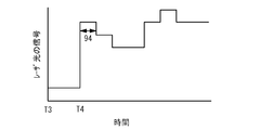
- FIG. 9 shows an example of a signal of laser light subjected to digital intensity modulation with the horizontal axis as time. For example, the intensity of the laser light is modulated to 256 gradations. As shown in FIG.
- the wavelength of the laser light 24 when the wavelength of the laser light 24 is modulated at a frequency higher than the sampling frequency of digital intensity modulation, a detection signal corresponding to the maximum time and the minimum time of the modulation signal is obtained within one pulse 94. Therefore, for example, when the laser system 100 is used for a laser display or the like, the wavelength of the laser light 24 can be controlled within a wavelength range that can be converted by the harmonic generation element 18 without being affected by the image. .
- the wavelength of the laser beam 24 is modulated at the same frequency as the sampling frequency of the digital intensity modulation, it is preferable to modulate the wavelength of the laser beam 24 using a modulation signal synchronized with the sampling of the digital modulation. In this case, a more appropriate detection signal can be obtained.
- the case where the intensity of the laser beam 24 is digitally modulated is shown as an example.
- the intensity of the laser beam 24 may be modulated by analog modulation. Regardless of whether the intensity modulation of the laser beam 24 is performed by digital modulation or analog modulation, by modulating the wavelength of the laser beam 24 at a frequency sufficiently higher than the frequency of intensity modulation of the laser beam 24, for example, laser
- the wavelength of the laser light 24 can be controlled within a wavelength range that can be converted by the harmonic generation element 18 without being affected by an image.
- the wavelength of the laser light 24 can be quickly brought into a wavelength range that can be converted by the harmonic generation element 18.
- the normal output state of the harmonic light 34 can be obtained more quickly.
- the control unit 40 controls the magnitude of the heater current 28 so as to reduce the difference between the detection signals described in step S18 of FIG. The case where there is no is preferable.
- the control unit 40 controls the magnitude of the heater current 28 when the intensity of the laser beam 24 is smaller than a predetermined gradation value. It can be avoided.
- the control unit 40 does not control the magnitude of the heater current 28 during the time T3 to T4, since the intensity of the laser light 24 is smaller than a predetermined gradation value, and after the time T4, the laser light is not controlled. Since the intensity of 24 is larger than the predetermined gradation value, the magnitude of the heater current 28 can be controlled.
- the intensity of the laser light 24 is small and dark, the intensity of the harmonic light 34 is also small and dark.
- the detection signal at the maximum and minimum of the modulation signal The difference becomes smaller.
- the position is shifted from the wavelength.
- the control unit 40 does not control the magnitude of the heater current 28 so as to reduce the amplitude of the detection signal when the intensity of the intensity-modulated laser light 24 is smaller than a predetermined threshold. Thereby, it can suppress adjusting the wavelength of the laser beam 24 outside the wavelength range which can be converted by the harmonic generation element 18.
- whether or not the intensity of the intensity-modulated laser beam 24 is smaller than a predetermined threshold may be determined based on whether or not the voltage value applied to the SOA 16 is smaller than the predetermined threshold. You may judge by the intensity
- the predetermined threshold value is a value that makes it difficult to adjust the wavelength of the laser light 24 within the wavelength range that can be converted by the harmonic generation element 18 as described above. For example, about 1/10 of the maximum detected intensity can be set as the threshold value.
- the storage unit 48 stores a table 80 in which the temperature of the laser module 10 and the heater power input to the heater 14 are associated with each other. Then, as described in step S20 of FIG. 5, the control unit 40 periodically adds new heater power to the table 80 based on the magnitude of the heater current 28 that is controlled so that the amplitude of the detection signal becomes small. Write information. Then, as described in step S ⁇ b> 12 of FIG. 5, when the power of the laser system 100 is turned on, the control unit 40 refers to the table 80 stored in the storage unit 48 and the current laser module 10. A heater power corresponding to the temperature is obtained and a heater current 28 is injected into the heater 14. Thereby, when the power of the laser system 100 is turned on, the wavelength of the laser light 24 oscillated by the DFB laser 12 can be easily and quickly adjusted within the wavelength range that can be converted by the harmonic generation element 18.
- the difference between the initial value of the heater power previously written in the table 80 stored in the storage unit 48 and the value of the newly written heater power is obtained.
- An error is output when the threshold is exceeded.
- the wavelength of the laser light 24 changes depending on the magnitude of the heater power. Therefore, the change in the heater power value means that the wavelength of the laser light 24 has changed.
- FIG. 10 shows an example of the relationship between the wavelength of the original laser beam 24 and the intensity of the harmonic light 34 when the laser system 100 is started to be used, and the laser beam when the table 80 is updated and a new value of heater power is written.
- strength of the harmonic light 34 is shown. As shown in FIG.
- the control unit 40 regards that the characteristics of the laser module 10 have changed and outputs an error.
- the predetermined threshold is a value that can be regarded as a change in the characteristics of the laser module 10 as described above.
- the threshold value can be set for a case where a deviation of 10% from the maximum input power to the heater 14 occurs.
- the case where the drive current 26 injected into the DFB laser 12 is modulated in order to modulate the wavelength of the laser light 24 oscillated by the DFB laser 12 is described as an example, but the present invention is not limited to this.
- the wavelength of the laser beam 24 may be modulated by other methods, such as when the heater current 28 injected into the heater 14 is modulated.
- the heater current 28 is modulated, there is an advantage that the intensity of the laser beam 24 oscillated by the DFB laser 12 can be made constant.
- the drive current 26 when the drive current 26 is modulated, there is an advantage that the response characteristic is excellent. Therefore, when the wavelength of the laser beam 24 is modulated at a high speed such as a frequency higher than the sampling frequency of digital intensity modulation, it is preferable to modulate the drive current 26.
- the intensity of the laser beam 24 is modulated at a frequency higher than the intensity modulation frequency of the laser beam 24 such that the wavelength of the laser beam 24 is modulated at a frequency higher than the sampling frequency of the digital intensity modulation.
- the wavelength of the laser beam 24 may be modulated at a frequency sufficiently lower than the frequency of intensity modulation of the laser beam 24.
- the wavelength of the laser beam 24 can be modulated at 1 kHz.
- the wavelength of the laser beam 24 can be controlled within a wavelength range that can be converted by the harmonic generation element 18.
- the laser is a quantum dot DFB laser.
- the present invention is not limited to this.
- the laser may be a quantum well DFB laser or the like, or may be a Fabry-Perot laser other than the DFB laser.
- the SOA 16 and the harmonic generation element 18 may be directly coupled.
- the harmonic generation element 18 converts the laser light 24 into the second harmonic of the laser light 24
- the harmonic generation element 18 has a higher order harmonic of the laser light 24. It may be converted into wave light.
- the case where the laser light 24 is 1064 nm and the harmonic light 34 is green light of 532 nm has been described as an example, but the harmonic light 34 may be light of other wavelengths.
- the laser beam 24 may have other wavelengths.
Landscapes
- Physics & Mathematics (AREA)
- Condensed Matter Physics & Semiconductors (AREA)
- General Physics & Mathematics (AREA)
- Electromagnetism (AREA)
- Optics & Photonics (AREA)
- Semiconductor Lasers (AREA)
- Optical Modulation, Optical Deflection, Nonlinear Optics, Optical Demodulation, Optical Logic Elements (AREA)
Abstract
本発明は、レーザ光24を発振するDFBレーザ12と、DFBレーザ12の温度を調節するヒータ14と、レーザ光24をレーザ光24の高調波光34に変換する高調波生成素子18と、を有するレーザモジュール10と、レーザ光24の波長を変調させて、高調波光34の強度から変調に用いた変調信号に同期した検出信号を検出し、検出信号の振幅が小さくなるようにヒータ14に注入するヒータ電流28の大きさを制御する制御部40と、を具備するレーザシステム100である。
Description
本発明は、レーザシステムに関し、特にレーザ光の高調波光を出射するレーザシステムに関する。
近年、レーザ光を出力するレーザシステムは、様々な分野で用いられている。特に、安価なレーザシステムには、半導体レーザが用いられている。しかしながら、半導体レーザには、発振が困難な波長帯の光(例えば、グリーン光)がある。そこで、DPSS(ダイオード励起固体レーザ)方式を用いて、半導体レーザでは発振が困難な波長帯の光を出射する方法が知られている。
DPSS方式では、レーザディスプレイ用途などで要求される、例えば50MHz程度の高速変調が困難である。そこで、半導体レーザが出射したレーザ光を非線形光学素子で高調波光に変換して出射するレーザシステムが提案されている(例えば、特許文献1)。
特許文献1のレーザシステムにおいて、非線形光学素子における高調波への変換効率を高めようとすると、許容される波長範囲が狭くなってしまう。半導体レーザと非線形光学素子とは異なる波長温度係数を有する。また、半導体レーザと非線形光学素子とは個別素子ごとに波長特性にバラツキも有する。このため、例えば、半導体レーザと非線形光学素子とが搭載されたレーザモジュールの温度が変化した場合に、レーザ光の波長を高効率で変換可能な波長範囲内に調整することは容易ではない。
また、半導体レーザの温度が局所的に変化する場合や半導体レーザそのものの特性が変化する場合がある。この場合、レーザモジュールの温度に基づいてレーザ光の波長を高効率で変換可能な波長範囲内に調整することは難しく、高調波光の強度が低下してしまう場合がある。
本発明は、上記課題に鑑みなされたものであり、高調波光を安定して出射することが可能なレーザシステムを提供することを目的とする。
本発明は、レーザ光を発振するレーザと、前記レーザの温度を調節するヒータと、前記レーザ光を前記レーザ光の高調波光に変換する高調波生成素子と、を有するレーザモジュールと、前記レーザ光の波長を変調させて、前記高調波光の強度から前記変調に用いた変調信号に同期した検出信号を求めて、前記検出信号の振幅が小さくなるように前記ヒータに注入するヒータ電流の大きさを制御する制御部と、を具備することを特徴とするレーザシステムである。本発明によれば、レーザ光の波長を高調波生成素子で変換可能な波長範囲内に制御することができ、高調波生成素子から安定して高調波光を出射させることができる。
上記構成において、前記制御部は、前記変調信号の極大時と極小時のそれぞれに対応する前記検出信号の差分の絶対値が小さくなるように前記ヒータ電流の大きさを制御することで、前記検出信号の振幅を小さくする構成とすることができる。
上記構成において、前記制御部は、前記レーザ光の強度を変調させると共に、前記レーザ光の強度変調の周波数よりも高い周波数で前記レーザ光の波長を変調させる構成とすることができる。この構成によれば、例えばレーザディスプレイなどに用いた場合でも、映像の影響を受けずに、レーザ光の波長を高調波生成素子で変換可能な波長範囲内に制御することができる。また、レーザ光の波長を素早く高調波生成素子で変換可能な波長範囲内に制御することができ、高調波光の正常な出力状態がより早く得られる。
上記構成において、前記レーザ光の強度変調をデジタル変調させる場合に、前記制御部は、前記デジタル変調でのサンプリング周波数よりも高い周波数で前記レーザ光の波長を変調させる構成とすることができる。
上記構成において、前記制御部は、前記レーザ光の強度をデジタル変調させると共に、前記デジタル変調でのサンプリングと同期した前記変調信号を用いて前記レーザ光の波長を変調させる構成とすることができる。この構成によれば、より適切な検出信号を得ることができる。
上記構成において、前記制御部は、前記レーザ光の強度を変調させると共に、前記レーザ光の強度変調の周波数よりも低い周波数で前記レーザ光の波長を変調させる構成とすることができる。この構成によれば、例えばレーザディスプレイなどに用いた場合でも、映像の影響を受けずに、レーザ光の波長を高調波生成素子で変換可能な波長範囲内にすることができる。
上記構成において、前記制御部は、強度変調した前記レーザ光の強度が所定の閾値より小さいときには、前記検出信号の振幅が小さくなるように前記ヒータに注入するヒータ電流の大きさの制御を行わない構成とすることができる。この構成によれば、レーザ光の波長を高調波生成素子で変換可能な波長範囲の外側に合わせ込むことを抑制できる。
上記構成において、前記制御部は、前記レーザを駆動する駆動電流の大きさを固定したまま、前記検出信号の振幅が小さくなるように前記ヒータに注入するヒータ電流の大きさを制御する構成とすることができる。この構成によれば、検出信号の振幅を小さくする制御を容易にすることができる。
上記構成において、前記レーザモジュールの温度と前記ヒータに投入するヒータ電力とを対応付けたテーブルを記憶する記憶部を具備し、前記制御部は、周期的に、前記検出信号の振幅が小さくなるように制御した前記ヒータ電流に基づいて前記テーブルに新たなヒータ電力を書き込むと共に、前記レーザシステムの電源が投入された際に、前記テーブルを参照して前記ヒータに前記ヒータ電流を注入する構成とすることができる。この構成によれば、レーザシステムの電源が投入された場合に、レーザ光の波長を高調波生成素子で変換可能な波長範囲内に容易に且つ素早く合わせることができる。
上記構成において、前記制御部は、前記テーブルに予め書き込まれていた前記ヒータ電力の初期値と前記テーブルに新たに書き込んだ前記ヒータ電力の値との差分が所定の閾値を超えた場合にエラーを出力する構成とすることができる。この構成によれば、特性劣化したレーザモジュールの判別および排除が可能となる。
本発明によれば、レーザ光の波長を高調波生成素子で変換可能な波長範囲内にすることができ、高調波生成素子から安定して高調波光を出射させることができる。
以下、図面を参照して、本発明の実施例を説明する。
図1は、実施例1に係るレーザシステムの例を示したブロック図である。図1のように、実施例1に係るレーザシステム100は、レーザモジュール10と、制御部40と、赤外光カットフィルタ42と、ビームスプリッタ44と、光検出器46と、記憶部48と、を有する。レーザモジュール10は、DFB(分布帰還型)レーザ12と、ヒータ14と、光半導体増幅器(SOA)16と、高調波生成素子18と、温度センサ20と、レンズ22と、を有する。SOA16と高調波生成素子18とは、レンズ22を介して光結合しており、SOA16から出射されたレーザ光24は高調波生成素子18に入射する。
DFBレーザ12は、コルゲーションを有し単一波長のレーザ光24を発振するレーザであり、例えば1064nmの波長を有するレーザ光24を発振する。DFBレーザ12は、制御部40により駆動電流26が注入されることで動作してレーザ光24を発振する。ヒータ14は、制御部40によりヒータ電流28が注入されることでDFBレーザ12の温度を調節する。SOA16は、制御部40により電圧30が印加されることでレーザ光24の強度を変調する。SOA16は、レーザ光24の強度を変化させるが、レーザ光24の波長は変化させない。DFBレーザ12とSOA16とは同一チップ上に形成されており、DFBレーザ12とSOA16の光軸は一致している。温度センサ20は、レーザモジュール10の温度をモニタし、制御部40に温度モニタ値32を出力する。
高調波生成素子18は、非線形光学素子であり、入射されたレーザ光24を高調波光34に変換する。高調波生成素子18は、例えばPPLN(Periodically Poled Lithium Niobate)であり、レーザ光24の第2高調波光である例えば532nmの波長を有する高調波光34を出射する。
赤外光カットフィルタ42は、高調波生成素子18から出射された光のうち赤外光を遮断し、高調波光34のみを通過させる。ビームスプリッタ44は、高調波光34の一部を分岐させて光検出器46に入射させる。光検出器46は、高調波光34の強度をモニタし、光出力モニタ信号49を制御部40に出力する。記憶部48は、例えば不揮発性メモリであり、レーザモジュール10の温度とヒータ14に投入するヒータ電力とを対応付けたテーブルが記憶されている。制御部40は、DFBレーザ12に注入する駆動電流26と、ヒータ14に注入するヒータ電流28と、SOA16に印加する電圧30とを制御する。
図2は、DFBレーザ12とSOA16の例を示した断面模式図である。図2のように、n型GaAs基板50上に、n型Al0.35Ga0.65Asからなるn型クラッド層52が形成されている。基板50下には電極54が形成されている。n型クラッド層52上に、GaAsからなるベース層56内にInAsからなる量子ドット58を有する量子ドット活性層60が形成されている。量子ドット活性層60上にp型GaAsからなるp型層62が形成されている。p型層62上にp型InGaPからなるp型クラッド層64が形成されている。DFBレーザ12のp型層62とp型クラッド層64との間には出射するレーザ光24の波長を決めるコルゲーション76が形成されている。基板50からp型クラッド層64までは、DFBレーザ12とSOA16とで共通である。
DFBレーザ12とSOA16とのp型クラッド層64上に、それぞれp+GaAsからなるコンタクト層66が形成されている。DFBレーザ12において、コンタクト層66上には電極68が形成されている。電極68上に酸化シリコンからなる絶縁膜70が形成されている。絶縁膜70上に例えばPtからなるヒータ14が形成されている。SOA16において、コンタクト層66上に電極72が形成されている。制御部40は、ワイヤ74を介して電極68、72およびヒータ14に電圧を印加する。電極54は、一定電位に接続されている。例えば接地されている。
制御部40は、DFBレーザ12の電極68に電圧を印加することにより、電極68と電極54との間に駆動電流26を流す。これにより、量子ドット活性層60で誘導放出が生じ、活性層60付近にレーザ光24が伝搬する。また、制御部40は、ヒータ14にヒータ電流28を流すことにより、DFBレーザ12の温度を制御する。さらに、制御部40は、電極72と電極54との間に電圧30を印加することにより、活性層60内のレーザ光24を増幅させる。電極72と電極54との間の電圧値を変化させることにより、SOA16の増幅率が変化するため、SOA16から出射するレーザ光24の強度を変調することができる。
図3は、DFBレーザ12が発振するレーザ光の波長と高調波生成素子18の変換効率を説明する模式図である。図3のように、高調波生成素子18による基本波から高調波への変換を高変換効率で行おうとすると、許容される波長範囲は領域36のような狭い波長範囲となる。以下において、高変換効率で基本波から高調波に変換できる波長を高調波生成素子18の位相整合波長と称すことにする。
図4(a)はDFBレーザ12が発振するレーザ光の波長とDFBレーザ12の駆動電流との関係を示す模式図である。図4(b)はDFBレーザ12が発振するレーザ光の波長とヒータ14のヒータ電力との関係を示す模式図である。図4(a)および図4(b)のように、駆動電流の大きさおよびヒータ電力の大きさが大きくなるに従い、DFBレーザ12が発振するレーザ光の波長は長波長側にシフトする。つまり、駆動電流の大きさおよびヒータ電力の大きさが変化するとDFBレーザ12が発振するレーザ光の波長は変化する。DFBレーザ12と高調波生成素子18とは異なる波長温度係数を有するが、駆動電流の大きさ及びヒータ電力の大きさを制御することで、DFBレーザ12が発振するレーザ光の波長を高調波生成素子18の位相整合波長に合わせることができる。
次に、図5のフローチャートを用いて、制御部40の制御の例について説明する。図5のように、レーザシステム100の電源が投入されると、制御部40は、トーン信号である変調信号を用いて変調した駆動電流26をDFBレーザ12に注入してレーザ光24を発振させる(ステップS10)。変調した駆動電流26の中心の大きさは、所定の大きさになるようにする。駆動電流26が変調されていることで、図4(a)で説明したように、発振されるレーザ光24の波長が変調される。変調信号の周波数は、後述するデジタル強度変調でのサンプリング周波数と同じか、あるいは高い周波数を用いる。例えば、サンプリング周波数が50MHzの場合、変調信号の周波数は50MHz、あるいは100MHzを用いる。サンプリング周波数と同じ周波数を用いる場合、波長変調はデジタル強度変調の制御クロックに同期させることが望ましい。
次いで、制御部40は、温度センサ20で出力された温度モニタ値32からレーザモジュール10の温度を把握する。そして、制御部40は、記憶部48に記憶されたテーブルからレーザモジュール10の温度に応じたヒータ電力を求めてヒータ14にヒータ電流28を投入する(ステップS12)。テーブルには、レーザモジュール10の温度とヒータ14に投入するヒータ電力との対応関係が書き込まれている。即ち、テーブルには、レーザモジュール10の温度がある温度の場合において、レーザ光24の波長を高調波生成素子18の位相整合波長に合わせることができるようなヒータ電力の大きさに関するデータが書き込まれている。前述したように、DFBレーザ12と高調波生成素子18とは異なる波長温度係数を有するため、レーザモジュール10の温度により、DFBレーザ12が発振するレーザ光24の波長と高調波生成素子18の位相整合波長との差が異なることになる。図4(b)で説明したように、ヒータ電力の大きさを変えることでレーザ光24の波長を変化させることができる。したがって、レーザモジュール10の温度とヒータ14に投入するヒータ電力との対応関係をテーブルに予め書き込んでおき、温度モニタ値32から把握したレーザモジュール10の温度とテーブルに書き込まれたデータとに基づいてヒータ電流28の大きさを制御することで、レーザ光24の波長を高調波生成素子18の位相整合波長に合わせることができる。これにより、高調波生成素子18から高調波光34を出射させることができる。
次いで、制御部40は、SOA16に変調した電圧30を印加して、レーザ光24の強度を変調させる(ステップS14)。レーザ光24の強度変調は、例えば256階調が表現されるようなデジタル強度変調により行う。
次いで、制御部40は、光検出器46で検出した高調波光34の強度から、駆動電流26を変調させた変調信号の周波数に同期した検出信号を検出する(ステップS16)。検出信号は、光検出器46が検出した高調波光34の強度から変調信号の周波数成分を抽出することで検出してもよいし、あるいは、光検出器46が変調信号の周波数に同期して高調波光34の強度の検出を行うことにより検出してもよい。制御部40は、変調信号の隣接する極大時と極小時での検出信号の大きさの差分を求め、その差分の絶対値が小さくなるように、ヒータ14に注入するヒータ電流28の大きさを制御する(ステップS18)。ヒータ14に注入するヒータ電流28の大きさを制御するときは、DFBレーザ12に注入する駆動電流26の大きさを変化させずに固定させておく。
ここで、図6および図7の模式図を用いて、図5のステップS10からステップS18で述べた制御について説明する。図6は、横軸を時間として、駆動電流26の変調に用いた変調信号と、変調信号に同期した検出信号と、の例を示している。図7は、レーザ光24の波長に対する高調波光34の強度およびレーザ光24の波長に対する変調信号の極大時と極小時での検出信号の差分(エラー信号)の例を示している。
図6のような変調信号を用いて駆動電流26を変調させてレーザ光24の波長を変調させた場合、レーザ光24の中心波長が高調波生成素子18の位相整合波長に合っているときは、高調波光34の強度は、例えば図7の領域82内を変化する。また、レーザ光24の中心波長が高調波生成素子18の位相整合波長よりも短波長側にズレているときは、高調波光34の強度は、例えば図7の領域84内を変化し、レーザ光24の波長が高調波生成素子18の位相整合波長よりも長波長側にズレているときは、高調波光34の強度は、例えば図7の領域86内を変化する。
ここで、例えば、DFBレーザ12の温度が局所的に変化した場合やDFBレーザ12そのものの特性が変化した場合などにより、レーザ光24の波長が高調波生成素子18の位相整合波長よりも短波長側にシフトした場合を考える。この場合、レーザ光24の波長が高調波生成素子18の位相整合波長に合うようにヒータ電流28の大きさを制御して、レーザ光24の波長を高調波生成素子18の短波長側と長波長側との間で変化させることになり、変調信号に同期した検出信号は例えば図6のようになる。図6において、例えば区間88は図7の領域84における検出信号に相当し、区間90は領域82における検出信号に相当し、区間92は領域86における検出信号に相当する。
図6において、変調信号の隣接する極大時と極小時(例えば、時間T1とT2)における検出信号の大きさの差分(例えば、M1-M2)をエラー信号とすると、レーザ光24の波長に対するエラー信号は図7のように表される。このことから、エラー信号が0に近づくほどレーザ光24の波長は高調波生成素子18の位相整合波長に近づくことがわかる。つまり、変調信号の隣接する極大時と極小時における検出信号の大きさの差分の絶対値が小さくなるほど、レーザ光24の波長は高調波生成素子18の位相整合波長に合うことになる。言い換えると、検出信号の振幅が小さくなるほど、レーザ光24の波長は高調波生成素子18の位相整合波長に合うことになる。よって、図5のステップS18を実行することで、レーザ光24の波長を高調波生成素子18の位相整合波長に合わせることができ、高調波生成素子18から高調波光34を出射させることができる。
図5に戻り、制御部40は、周期的に、記憶部48に記憶されたテーブルを更新し、ステップS18でレーザ光24の波長が高調波生成素子18の位相整合波長に合うように制御したヒータ電流28の大きさに基づいて新たなヒータ電力をテーブルに書き込む(ステップS20)。次いで、制御部40は、記憶部48に予め書き込まれていたヒータ電力の初期値とステップS20で書き込んだ新たなヒータ電力との差分を求める。そして、制御部40は、その差分が所定の閾値を超えている場合に、レーザモジュール10は異常であるとしてエラーを出力する(ステップS22)。
ここで、図8(a)および図8(b)の模式図を用いて、記憶部48に記憶されるテーブル80について説明する。図8(a)は、図5のステップS20の工程が実行される前の初期状態のテーブル80の例を示しており、図8(b)は、図5のステップS20の工程が例えば1回実行された後のテーブル80の例を示している。
図8(a)のように、初期状態のテーブル80は、レーザモジュール10の温度が、例えば0℃、20℃、50℃、70℃の場合に応じたヒータ電力の初期値A、B、C、Dが予め書き込まれている。ステップS20の工程が1回実行された後のテーブル80は、図8(b)のように、例えばレーザモジュール10の温度が20℃の場合のヒータ電力に新たなヒータ電力の値B1が書き込まれている。このように、図5のステップS18の工程で制御したヒータ電流28の大きさに基づいて新たなヒータ電力がテーブル80に書き込まれる。よって、図5のステップS22の工程は、B1とBとの差分が所定の閾値を超えている場合に、レーザモジュール10が異常であるとしてエラーを出力することになる。
以上説明してきたように、実施例1に係るレーザシステム100によれば、制御部40は、DFBレーザ12を駆動する駆動電流26を変調して、DFBレーザ12が発振するレーザ光24の波長を変調させる。そして、制御部40は、光検出器46で検出した高調波光34の強度から変調信号に同期した検出信号を検出し、検出信号の振幅が小さくなるように、ヒータ14に注入するヒータ電流28の大きさを制御する。例えば、制御部40は、変調信号の隣接する極大時と極小時のそれぞれに対応する検出信号の差分の絶対値が小さくなるように、ヒータ14に注入するヒータ電流28の大きさを制御する。これにより、図6および図7で説明したように、DFBレーザ12が発振するレーザ光24の波長を高調波生成素子18で変換可能な波長範囲内に制御することができ、高調波生成素子18から安定して高調波光34を出射させることができる。
レーザモジュール10の温度に基づいてヒータ電流28の大きさを制御してレーザ光24の波長を高調波生成素子18で変換可能な波長範囲内にする方法では、DFBレーザ12の温度が局所的に変化した場合やDFBレーザ12そのものの特性が変化した場合など、レーザモジュール10の温度が変化しない場合には対応することができない。しかしながら、実施例1に係るレーザシステム100は、高調波光34の強度を利用してヒータ電流28の大きさを制御することで、レーザ光24の波長を高調波生成素子18で変換可能な波長範囲内になるようにしている。このため、DFBレーザ12の温度が局所的に変化した場合やDFBレーザ12そのものの特性が変化した場合などにも対応でき、安定して高調波光34を出射させることができる。
図5のステップS18で説明したように、検出信号の振幅が小さくなるようにヒータ電流28の大きさを制御するときは、DFBレーザ12の駆動電流26の大きさは変化させずに固定したままにする。DFBレーザ12の駆動電流26を変化させると、レーザ光24の波長および強度が変化するため、検出信号の振幅を小さくするための制御などが複雑になる。したがって、検出信号の振幅を小さくする制御を容易にする観点などから、制御部40は、DFBレーザ12を駆動する駆動電流26の大きさは固定にしたまま、検出信号の振幅が小さくなるようにヒータ14に注入するヒータ電流28の大きさを制御することが好ましい。
図5のステップS14で説明したように、制御部40は、レーザ光24の強度をデジタル強度変調している。そして、制御部40は、デジタル強度変調のサンプリング周波数よりも高い周波数の変調信号を用いて駆動電流26を変調させてレーザ光24の波長を変調している。つまり、制御部40は、デジタル強度変調のサンプリング周波数よりも高い周波数でレーザ光24の波長を変調させている。図9は、横軸を時間として、デジタル強度変調されたレーザ光の信号の例を示している。レーザ光は、例えば256階調に強度変調される。図9のように、デジタル強度変調のサンプリング周波数よりも高い周波数でレーザ光24の波長を変調させると、1つのパルス94内で変調信号の極大時と極小時に対応する検出信号が得られる。このため、例えばレーザシステム100をレーザディスプレイ用途などに用いた場合に、映像の影響を受けずに、レーザ光24の波長を高調波生成素子18で変換可能な波長範囲内に制御することができる。
また、デジタル強度変調のサンプリング周波数と同じ周波数でレーザ光24の波長を変調させる場合は、デジタル変調のサンプリングと同期した変調信号を用いてレーザ光24の波長を変調させる場合が好ましい。この場合、より適切な検出信号を得ることができる。
なお、実施例1では、レーザ光24の強度をデジタル変調させる場合を例に示したが、アナログ変調によりレーザ光24の強度を変調させる場合でもよい。レーザ光24の強度変調をデジタル変調およびアナログ変調のどちらで行う場合であっても、レーザ光24の強度変調の周波数よりも十分に高い周波数でレーザ光24の波長を変調させることで、例えばレーザシステム100をレーザディスプレイ用途などに用いた場合に、映像の影響を受けずに、レーザ光24の波長を高調波生成素子18で変換可能な波長範囲内に制御することができる。
また、レーザ光24の強度変調の周波数よりも高い周波数でレーザ光24の波長を変調させることで、レーザ光24の波長を素早く高調波生成素子18で変換可能な波長範囲内にすることができ、高調波光34の正常な出力状態がより早く得られる。
制御部40は、強度変調したレーザ光24の強度が所定の閾値よりも小さいときには、図5のステップS18で説明した、検出信号の差分を小さくするようなヒータ電流28の大きさの制御は行わない場合が好ましい。例えば、制御部40は、レーザ光24の強度を256階調でデジタル強度変調する場合、レーザ光24の強度が所定の階調値よりも小さい場合には、ヒータ電流28の大きさの制御を行わないようにすることができる。例えば、図9において、制御部40は、時間T3からT4の間はレーザ光24の強度が所定の階調値より小さいためヒータ電流28の大きさの制御を行わず、時間T4以降はレーザ光24の強度が所定の階調値より大きいためヒータ電流28の大きさの制御を行うようにすることができる。
レーザ光24の強度が小さく暗い場合には、高調波光34の強度も小さく暗くなる。このような場合、図7の領域84や86のようにレーザ光24の波長が高調波生成素子18の位相整合波長からズレている場合でも、変調信号の極大時と極小時での検出信号の差分が小さくなってしまう。このため、レーザ光24の波長を高調波生成素子18の位相整合波長に合うようにヒータ電流28の大きさを制御することが困難となり、レーザ光24の波長が高調波生成素子18の位相整合波長からズレた位置に合わせ込まれる場合が起こり得る。したがって、制御部40は、強度変調したレーザ光24の強度が所定の閾値よりも小さい場合は、検出信号の振幅を小さくするようなヒータ電流28の大きさの制御は行わない場合が好ましい。これにより、レーザ光24の波長を高調波生成素子18で変換可能な波長範囲の外側に合わせ込むことを抑制できる。強度変調したレーザ光24の強度が所定の閾値よりも小さいかどうかの判断は、上記の他に、SOA16に印加する電圧値が所定の閾値よりも小さいかどうかにより判断してもよいし、光検出器46で検出した高調波光34の強度が所定の閾値よりも小さいかどうかにより判断してもよい。なお、所定の閾値とは、上述のように、レーザ光24の波長を高調波生成素子18で変換可能な波長範囲内に合わせ込むことが困難になる程度の値をいう。例えば、最大検出強度の1/10程度を閾値として設定することができる。
図1のように、レーザモジュール10の温度とヒータ14に投入するヒータ電力とを対応付けたテーブル80を記憶する記憶部48を有する。そして、図5のステップS20で説明したように、制御部40は、周期的に、検出信号の振幅が小さくなるように制御したヒータ電流28の大きさに基づいてテーブル80に新たなヒータ電力の情報を書き込む。そして、図5のステップS12で説明したように、レーザシステム100の電源が投入された際に、制御部40は、記憶部48に記憶されたテーブル80を参照して、現在のレーザモジュール10の温度に対応したヒータ電力を求めてヒータ14にヒータ電流28を注入する。これにより、レーザシステム100の電源が投入された場合に、DFBレーザ12が発振するレーザ光24の波長を高調波生成素子18で変換可能な波長範囲内に容易に且つ素早く合わせることができる。
図5のステップS22で説明したように、記憶部48が記憶するテーブル80に予め書き込まれていたヒータ電力の初期値と新たに書き込んだヒータ電力の値との差分を求め、その差分が所定の閾値を超えた場合にエラーを出力する。図4(b)で説明したように、レーザ光24の波長はヒータ電力の大きさにより変化することから、ヒータ電力の値が変わったということは、レーザ光24の波長が変化したことになる。図10は、レーザシステム100を使用開始した当初のレーザ光24の波長と高調波光34の強度との関係の例と、テーブル80を更新して新たな値のヒータ電力を書き込んだときのレーザ光24の波長と高調波光34の強度との関係の例と、を示している。図10のように、使用開始当初は、レーザ光24の波長が例えばλ0にて高調波生成素子18の位相整合波長に合っていたが、テーブル80を更新したときは、レーザ光24の波長が例えばλ1にて高調波生成素子18の位相整合波長にあっている場合を想定する。この場合、レーザモジュール10の特性が変化したと考えられる。したがって、ヒータ電力の初期値と新たに書き込んだヒータ電力の値との差分が所定の閾値を超えた場合は、制御部40は、レーザモジュール10の特性が変化したとみなして、エラーを出力する場合が好ましい。これにより、特性劣化したレーザモジュール10の判別および排除が可能となる。なお、所定の閾値とは、上述したように、レーザモジュール10の特性が変化したとみなすことができる程度の値をいう。例えば、ヒータ14への最大投入電力に対して10%ずれた場合を閾値として設定することができる。
実施例1では、DFBレーザ12が発振するレーザ光24の波長を変調させるために、DFBレーザ12に注入する駆動電流26を変調させる場合を例に示したが、これに限られるわけではなく、ヒータ14に注入するヒータ電流28を変調させる場合など、その他の方法によりレーザ光24の波長を変調させてもよい。ヒータ電流28を変調させる場合は、DFBレーザ12が発振するレーザ光24の強度を一定にすることができる利点がある。一方、駆動電流26を変調させる場合は、応答特性に優れているとの利点がある。したがって、レーザ光24の波長を、例えばデジタル強度変調のサンプリング周波数よりも高い周波数のように、高速で変調させる場合は、駆動電流26を変調させる場合が好ましい。
また、実施例1では、デジタル強度変調のサンプリング周波数よりも高い周波数でレーザ光24の波長を変調させるような、レーザ光24の強度変調の周波数よりも高い周波数でレーザ光24の強度を変調させる場合を例に示したが、これに限られない。例えば、レーザ光24の強度変調の周波数よりも十分に低い周波数でレーザ光24の波長を変調させる場合でもよい。例えば、レーザ光24の強度変調を50MHzで行う場合、レーザ光24の波長の変調は1kHzで行うことができる。このように、レーザ光24の強度変調の周波数よりも十分に低い周波数でレーザ光24の波長を変調させた場合でも、例えばレーザシステム100をレーザディスプレイ用途などに用いた場合に、映像の影響を受けずに、レーザ光24の波長を高調波生成素子18で変換可能な波長範囲内に制御することができる。
また、実施例1では、レーザは量子ドットDFBレーザである場合を例に示したが、これに限られるわけではない。例えば、レーザは、量子井戸DFBレーザなどの場合でもよいし、DFBレーザ以外の例えばファブリペロ型レーザである場合でもよい。また、SOA16と高調波生成素子18とはレンズ22を介して光結合している場合を例に示したが、SOA16と高調波生成素子18とが直接結合している場合でもよい。
また、実施例1では、高調波生成素子18が、レーザ光24をレーザ光24の第2高調波に変換する例を説明したが、高調波生成素子18はレーザ光24のより高次な高調波光に変換してもよい。また、レーザ光24が1064nmであり、高調波光34が532nmのグリーン光の場合を例に説明したが、高調波光34は他の波長の光でもよい。またレーザ光24はその他の波長を有してもよい。
以上、本発明の好ましい実施例について詳述したが、本発明は係る特定の実施例に限定されるものではなく、特許請求の範囲に記載された本発明の要旨の範囲内において、種々の変形・変更が可能である。
Claims (10)
- レーザ光を発振するレーザと、前記レーザの温度を調節するヒータと、前記レーザ光を前記レーザ光の高調波光に変換する高調波生成素子と、を有するレーザモジュールと、
前記レーザ光の波長を変調させて、前記高調波光の強度から前記変調に用いた変調信号に同期した検出信号を検出し、前記検出信号の振幅が小さくなるように前記ヒータに注入するヒータ電流の大きさを制御する制御部と、を具備することを特徴とするレーザシステム。 - 前記制御部は、前記変調信号の極大時と極小時のそれぞれに対応する前記検出信号の差分の絶対値が小さくなるように前記ヒータ電流の大きさを制御することで、前記検出信号の振幅を小さくすることを特徴とする請求項1記載のレーザシステム。
- 前記制御部は、前記レーザ光の強度を変調させると共に、前記レーザ光の強度変調の周波数よりも高い周波数で前記レーザ光の波長を変調させることを特徴とする請求項1または2記載のレーザシステム。
- 前記レーザ光の強度変調をデジタル変調させる場合に、前記制御部は、前記デジタル変調でのサンプリング周波数よりも高い周波数で前記レーザ光の波長を変調させることを特徴とする請求項3記載のレーザシステム。
- 前記制御部は、前記レーザ光の強度をデジタル変調させると共に、前記デジタル変調でのサンプリングと同期した前記変調信号を用いて前記レーザ光の波長を変調させることを特徴とする請求項1または2記載のレーザシステム。
- 前記制御部は、前記レーザ光の強度を変調させると共に、前記レーザ光の強度変調の周波数よりも低い周波数で前記レーザ光の波長を変調させることを特徴とする請求項1または2記載のレーザシステム。
- 前記制御部は、強度変調した前記レーザ光の強度が所定の閾値より小さいときには、前記検出信号の振幅が小さくなるように前記ヒータに注入するヒータ電流の大きさの制御を行わないことを特徴とする請求項3から6のいずれか一項記載のレーザシステム。
- 前記制御部は、前記レーザを駆動する駆動電流の大きさを固定したまま、前記検出信号の振幅が小さくなるように前記ヒータに注入するヒータ電流の大きさを制御することを特徴とする請求項1から7のいずれか一項記載のレーザシステム。
- 前記レーザモジュールの温度と前記ヒータに投入するヒータ電力とを対応付けたテーブルを記憶する記憶部を具備し、
前記制御部は、周期的に、前記検出信号の振幅が小さくなるように制御した前記ヒータ電流に基づいて前記テーブルに新たなヒータ電力を書き込むと共に、前記レーザシステムの電源が投入された際に、前記テーブルを参照して前記ヒータにヒータ電流を注入することを特徴とする請求項1から8のいずれか一項記載のレーザシステム。 - 前記制御部は、前記テーブルに予め書き込まれていた前記ヒータ電力の初期値と前記テーブルに新たに書き込んだ前記ヒータ電力の値との差分が所定の閾値を超えた場合にエラーを出力することを特徴とする請求項9記載のレーザシステム。
Priority Applications (2)
| Application Number | Priority Date | Filing Date | Title |
|---|---|---|---|
| US13/635,493 US20130010821A1 (en) | 2010-03-18 | 2011-03-04 | Laser system |
| EP11756096A EP2549327A1 (en) | 2010-03-18 | 2011-03-04 | Laser system |
Applications Claiming Priority (2)
| Application Number | Priority Date | Filing Date | Title |
|---|---|---|---|
| JP2010063111A JP5180250B2 (ja) | 2010-03-18 | 2010-03-18 | レーザシステム |
| JP2010-063111 | 2010-03-18 |
Publications (1)
| Publication Number | Publication Date |
|---|---|
| WO2011114907A1 true WO2011114907A1 (ja) | 2011-09-22 |
Family
ID=44649007
Family Applications (1)
| Application Number | Title | Priority Date | Filing Date |
|---|---|---|---|
| PCT/JP2011/055016 WO2011114907A1 (ja) | 2010-03-18 | 2011-03-04 | レーザシステム |
Country Status (5)
| Country | Link |
|---|---|
| US (1) | US20130010821A1 (ja) |
| EP (1) | EP2549327A1 (ja) |
| JP (1) | JP5180250B2 (ja) |
| TW (1) | TW201138243A (ja) |
| WO (1) | WO2011114907A1 (ja) |
Cited By (1)
| Publication number | Priority date | Publication date | Assignee | Title |
|---|---|---|---|---|
| JP2015130500A (ja) * | 2013-12-31 | 2015-07-16 | フルークコーポレイションFluke Corporation | 光ネットワーク試験機器内の光源の安定性改善の方法及びコンピュータ・プログラム・プロダクト |
Families Citing this family (8)
| Publication number | Priority date | Publication date | Assignee | Title |
|---|---|---|---|---|
| JP5362301B2 (ja) * | 2008-09-19 | 2013-12-11 | 株式会社Qdレーザ | レーザシステム |
| JP5853599B2 (ja) * | 2011-11-01 | 2016-02-09 | 富士通株式会社 | 発光装置及びその制御方法 |
| US9410890B2 (en) * | 2012-03-19 | 2016-08-09 | Kla-Tencor Corporation | Methods and apparatus for spectral luminescence measurement |
| US9281659B1 (en) | 2014-09-22 | 2016-03-08 | Seagate Technology Llc | Thermal management of laser diode mode hopping for heat assisted media recording |
| US9905996B2 (en) * | 2014-09-22 | 2018-02-27 | Seagate Technology Llc | Heat assisted media recording device with reduced likelihood of laser mode hopping |
| CN104466673B (zh) * | 2014-10-16 | 2017-06-13 | 浙江大学 | 补偿超辐射发光二极管光源波长温度漂移的装置和方法 |
| JP6508956B2 (ja) * | 2015-01-28 | 2019-05-08 | 富士通株式会社 | 変調光源 |
| JP2018046210A (ja) * | 2016-09-15 | 2018-03-22 | 住友電工デバイス・イノベーション株式会社 | 光半導体装置及び光半導体装置の制御方法 |
Citations (7)
| Publication number | Priority date | Publication date | Assignee | Title |
|---|---|---|---|---|
| JPH06132595A (ja) | 1992-10-16 | 1994-05-13 | Takatomo Sasaki | 第2次高調波光発生装置 |
| JP2002158383A (ja) * | 2000-11-17 | 2002-05-31 | Fuji Photo Film Co Ltd | レーザ光源の適正駆動温度を決定するための方法および装置 |
| WO2003001635A1 (fr) * | 2001-06-22 | 2003-01-03 | Matsushita Electric Industrial Co., Ltd. | Appareil a source lumineuse et son procede de commande |
| JP2005327839A (ja) * | 2004-05-13 | 2005-11-24 | Miyachi Technos Corp | 高調波レーザ発生方法及び高調波レーザ装置 |
| JP2006011332A (ja) * | 2004-06-29 | 2006-01-12 | Canon Inc | 画像投影装置及び画像投影装置におけるdfbレーザの制御方法 |
| JP2008140820A (ja) * | 2006-11-30 | 2008-06-19 | Seiko Epson Corp | レーザ光源装置の駆動方法、レーザ光源装置、画像表示装置、モニタ装置、照明装置 |
| WO2008140768A1 (en) * | 2007-05-11 | 2008-11-20 | Corning Incorporated | Alignment of lasing wavelength with wavelength conversion peak using modulated wavelength control signal |
Family Cites Families (1)
| Publication number | Priority date | Publication date | Assignee | Title |
|---|---|---|---|---|
| US7680364B2 (en) * | 2001-10-09 | 2010-03-16 | Infinera Corporation | Wavelength locking and power control systems for multi-channel photonic integrated circuits (PICS) |
-
2010
- 2010-03-18 JP JP2010063111A patent/JP5180250B2/ja active Active
-
2011
- 2011-03-04 US US13/635,493 patent/US20130010821A1/en not_active Abandoned
- 2011-03-04 WO PCT/JP2011/055016 patent/WO2011114907A1/ja active Application Filing
- 2011-03-04 EP EP11756096A patent/EP2549327A1/en not_active Withdrawn
- 2011-03-16 TW TW100108908A patent/TW201138243A/zh unknown
Patent Citations (7)
| Publication number | Priority date | Publication date | Assignee | Title |
|---|---|---|---|---|
| JPH06132595A (ja) | 1992-10-16 | 1994-05-13 | Takatomo Sasaki | 第2次高調波光発生装置 |
| JP2002158383A (ja) * | 2000-11-17 | 2002-05-31 | Fuji Photo Film Co Ltd | レーザ光源の適正駆動温度を決定するための方法および装置 |
| WO2003001635A1 (fr) * | 2001-06-22 | 2003-01-03 | Matsushita Electric Industrial Co., Ltd. | Appareil a source lumineuse et son procede de commande |
| JP2005327839A (ja) * | 2004-05-13 | 2005-11-24 | Miyachi Technos Corp | 高調波レーザ発生方法及び高調波レーザ装置 |
| JP2006011332A (ja) * | 2004-06-29 | 2006-01-12 | Canon Inc | 画像投影装置及び画像投影装置におけるdfbレーザの制御方法 |
| JP2008140820A (ja) * | 2006-11-30 | 2008-06-19 | Seiko Epson Corp | レーザ光源装置の駆動方法、レーザ光源装置、画像表示装置、モニタ装置、照明装置 |
| WO2008140768A1 (en) * | 2007-05-11 | 2008-11-20 | Corning Incorporated | Alignment of lasing wavelength with wavelength conversion peak using modulated wavelength control signal |
Cited By (1)
| Publication number | Priority date | Publication date | Assignee | Title |
|---|---|---|---|---|
| JP2015130500A (ja) * | 2013-12-31 | 2015-07-16 | フルークコーポレイションFluke Corporation | 光ネットワーク試験機器内の光源の安定性改善の方法及びコンピュータ・プログラム・プロダクト |
Also Published As
| Publication number | Publication date |
|---|---|
| TW201138243A (en) | 2011-11-01 |
| JP2011197300A (ja) | 2011-10-06 |
| EP2549327A1 (en) | 2013-01-23 |
| US20130010821A1 (en) | 2013-01-10 |
| JP5180250B2 (ja) | 2013-04-10 |
Similar Documents
| Publication | Publication Date | Title |
|---|---|---|
| JP5180250B2 (ja) | レーザシステム | |
| KR101399708B1 (ko) | 반도체 레이저의 파장 선택, 위상, 및 이득 영역에서의 파장 조절 | |
| JP4693364B2 (ja) | 光波長変換装置、その制御方法、およびそれを用いた画像投影装置 | |
| JP2010527164A (ja) | 変調波長制御信号を用いるレーザ発振波長の波長変換ピークとの整合 | |
| US7483458B2 (en) | Wavelength control in semiconductor lasers | |
| JP5853599B2 (ja) | 発光装置及びその制御方法 | |
| JP2012257164A (ja) | 半導体光変調器の駆動制御装置 | |
| JP2004247968A (ja) | 光送信器 | |
| JP5362301B2 (ja) | レーザシステム | |
| JP6032601B2 (ja) | 半導体光増幅器の制御方法及び測定方法、並びに半導体光増幅装置 | |
| JP6862106B2 (ja) | 電流制御装置及びレーザ装置 | |
| US8204091B2 (en) | Wavelength normalization in phase section of semiconductor lasers | |
| JP2012043994A (ja) | レーザシステム | |
| TW201112551A (en) | Minimizing power variations in laser sources | |
| US7400659B2 (en) | Method and device for performing DBR laser wavelength modulation free of thermal effect | |
| WO2011114906A1 (ja) | レーザシステムおよびその製造方法 | |
| KR20100120284A (ko) | 레이저 공급원의 파워 변화를 최소화하는 방법 및 시스템 | |
| JP2011029426A (ja) | レーザシステム | |
| JP2005091517A (ja) | 光変調素子のバイアス電圧制御方法及び安定化光変調器 | |
| JPS61133688A (ja) | 半導体レ−ザ波長制御装置 | |
| KR101096906B1 (ko) | 고조파 레이저 발생 장치 및 그 구동 방법 | |
| JPS61133687A (ja) | 半導体レ−ザ波長制御装置 | |
| JP2012242621A (ja) | 光送信器の制御方法及び光送信器 | |
| JP2008070493A (ja) | 光波長変換装置、及びそれを用いた画像形成装置 |
Legal Events
| Date | Code | Title | Description |
|---|---|---|---|
| 121 | Ep: the epo has been informed by wipo that ep was designated in this application |
Ref document number: 11756096 Country of ref document: EP Kind code of ref document: A1 |
|
| WWE | Wipo information: entry into national phase |
Ref document number: 13635493 Country of ref document: US |
|
| NENP | Non-entry into the national phase |
Ref country code: DE |
|
| WWE | Wipo information: entry into national phase |
Ref document number: 2011756096 Country of ref document: EP |