WO2011114679A1 - アーク溶接装置 - Google Patents
アーク溶接装置 Download PDFInfo
- Publication number
- WO2011114679A1 WO2011114679A1 PCT/JP2011/001450 JP2011001450W WO2011114679A1 WO 2011114679 A1 WO2011114679 A1 WO 2011114679A1 JP 2011001450 W JP2011001450 W JP 2011001450W WO 2011114679 A1 WO2011114679 A1 WO 2011114679A1
- Authority
- WO
- WIPO (PCT)
- Prior art keywords
- welding
- time
- current
- welding current
- arc
- Prior art date
- Legal status (The legal status is an assumption and is not a legal conclusion. Google has not performed a legal analysis and makes no representation as to the accuracy of the status listed.)
- Ceased
Links
Images

Classifications
-
- B—PERFORMING OPERATIONS; TRANSPORTING
- B23—MACHINE TOOLS; METAL-WORKING NOT OTHERWISE PROVIDED FOR
- B23K—SOLDERING OR UNSOLDERING; WELDING; CLADDING OR PLATING BY SOLDERING OR WELDING; CUTTING BY APPLYING HEAT LOCALLY, e.g. FLAME CUTTING; WORKING BY LASER BEAM
- B23K9/00—Arc welding or cutting
- B23K9/16—Arc welding or cutting making use of shielding gas
- B23K9/167—Arc welding or cutting making use of shielding gas and of a non-consumable electrode
-
- B—PERFORMING OPERATIONS; TRANSPORTING
- B23—MACHINE TOOLS; METAL-WORKING NOT OTHERWISE PROVIDED FOR
- B23K—SOLDERING OR UNSOLDERING; WELDING; CLADDING OR PLATING BY SOLDERING OR WELDING; CUTTING BY APPLYING HEAT LOCALLY, e.g. FLAME CUTTING; WORKING BY LASER BEAM
- B23K9/00—Arc welding or cutting
- B23K9/06—Arrangements or circuits for starting the arc, e.g. by generating ignition voltage, or for stabilising the arc
- B23K9/067—Starting the arc
-
- B—PERFORMING OPERATIONS; TRANSPORTING
- B23—MACHINE TOOLS; METAL-WORKING NOT OTHERWISE PROVIDED FOR
- B23K—SOLDERING OR UNSOLDERING; WELDING; CLADDING OR PLATING BY SOLDERING OR WELDING; CUTTING BY APPLYING HEAT LOCALLY, e.g. FLAME CUTTING; WORKING BY LASER BEAM
- B23K9/00—Arc welding or cutting
- B23K9/09—Arrangements or circuits for arc welding with pulsed current or voltage
- B23K9/091—Arrangements or circuits for arc welding with pulsed current or voltage characterised by the circuits
- B23K9/092—Arrangements or circuits for arc welding with pulsed current or voltage characterised by the circuits characterised by the shape of the pulses produced
-
- B—PERFORMING OPERATIONS; TRANSPORTING
- B23—MACHINE TOOLS; METAL-WORKING NOT OTHERWISE PROVIDED FOR
- B23K—SOLDERING OR UNSOLDERING; WELDING; CLADDING OR PLATING BY SOLDERING OR WELDING; CUTTING BY APPLYING HEAT LOCALLY, e.g. FLAME CUTTING; WORKING BY LASER BEAM
- B23K2103/00—Materials to be soldered, welded or cut
- B23K2103/08—Non-ferrous metals or alloys
- B23K2103/10—Aluminium or alloys thereof
Definitions
- welding work is performed with a large current in the range of 300 A or more and 500 A or less in order to increase work efficiency.
- a conventional AC arc welding apparatus for example, a TIG welding apparatus
- heat loss of a semiconductor that mainly operates inside the apparatus becomes large. Therefore, it is necessary to employ a semiconductor with a slow switching speed in order to reduce the on loss (product of the on-resistance of the main transistor and the energization current). As a result, the switching loss increases, so that the inverter frequency cannot be increased. Therefore, the circuit configuration operates at an inverter frequency of a relatively low frequency (for example, up to about 10 kHz). Accordingly, it is necessary to mount a reactor having a large inductance value in order to prevent arc breakage in a low current region (for example, up to about 10 A).
- FIG. 4 is a diagram showing a schematic configuration of a conventional arc welding apparatus
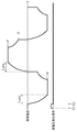
- FIG. 5 is a diagram showing a time change of a welding current waveform in the conventional arc welding apparatus.
- the operation of a conventionally used arc welding apparatus will be described with reference to FIGS.
- a non-consumable electrode type AC arc welding apparatus that performs welding by alternately repeating a reverse polarity period and a positive polarity period will be described.
- the arc welding apparatus 22 includes a current detection unit 4 that detects a welding current, a high voltage generation unit 8, an output unit 19 that performs welding output, and a control unit 20 that controls the output unit 19. And a reactor 21 provided between the output unit 19 and the welding torch 10.
- the high voltage generator 8 applies a high voltage between the electrode 9 provided in the welding torch 10 and the base material 12 as a welding object.
- a welding torch 10 provided with an electrode 9 and a base material 12 as a welding object are connected to the arc welding device 22, and an arc 11 is generated between the electrode 9 and the base material 12 to perform welding. I do.
- IP indicates a peak current value
- IS indicates a start current value
- E1 indicates a welding start time that is a time when welding is started
- E2 indicates a current detection time that is a time when current is detected by the current detection unit 4.
- TUP3 indicates the rise time at the time of the conventional arc start
- TUP4 indicates the rise time at the time of the conventional steady welding.
- I3 has shown the electric current value before the polarity of a welding current commutates from positive polarity to reverse polarity.
- FIG. 4 commercial power input (for example, using 200 V or the like) fed from an external device such as a switchboard is fed to the output unit 19 of the arc welding apparatus 22.
- the output unit 19 outputs a welding current and a welding voltage suitable for welding by inverter control driven at an inverter frequency of about 10 kHz based on the welding control signal output by the control unit 20.
- the welding current and welding voltage output from the output unit 19 are smoothed through the reactor 21 and supplied to the welding torch 10 and the base material 12, and an arc 11 is generated between the tip of the electrode 9 and the base material 12. AC arc welding is performed.
- the inductance value of the reactor 21 needs to be 200 ⁇ H or more so that the arc does not break at a low current (for example, about 10 A). This inductance value is determined based on, for example, experiments and calculations.
- control unit 20 outputs a high voltage generation signal to the high voltage generation unit 8 to turn on the high voltage generation signal at the start of the arc start. Thereafter, the control unit 20 receives the current detection signal output from the current detection unit 4 and generates a high voltage when the current detection unit 4 detects the current and receives a signal indicating that the current detection unit 4 has detected the current. Turn off the signal.
- the high voltage generator 8 generates a voltage (for example, 15 kV) higher than the voltage at the time of steady welding, and between the electrode 9 and the base material 12 while the high voltage generation signal is on at the time of arc start. A high voltage is applied, and the application of the high voltage is stopped while the high voltage generation signal is off.
- a voltage for example, 15 kV
- the control unit 20 turns on the drive of the output unit 19 and applies a no-load voltage between the electrode 9 and the base material 12 by the output unit 19. Further, the control unit 20 turns on the high voltage generation signal and applies a high voltage for arc start by the high voltage generation unit 8. Thereafter, at the current detection time point E2 when the arc is generated and the current detection 4 detects the current, the control unit 20 turns off the high voltage generation signal and stops the application of the high voltage.
- the welding current rises at 500 A / msec and reaches a start current value IS (for example, 350 A).
- the welding current rises at 500 A / msec and reaches the absolute value IP (eg, 350 A) of the peak current during the rise time TUP4 from the zero crossing point when the polarity of the welding current commutates. .
- IP absolute value
- the rise of the welding current at the start of the arc and the rise of the welding current during the steady welding period are determined by the inductance value of the reactor 21.
- the rise means an increase amount of the welding current per unit time until the peak current is reached.
- the current command for AC welding is generally in the form of a pulse, and it is generally considered that the rise is better so that the actual current waveform is in the form of a pulse.
- the rise of current increases (for example, 1500 A / msec or more), and the arc start performance is dramatically improved.
- the present invention provides an arc welding apparatus having good arc start performance and good workability of the filler wire during high current welding.
- An arc welding apparatus is a non-consumable electrode type arc welding apparatus that performs welding by outputting an AC pulse having an absolute value of a peak current of 300 A or more and 1500 A or less, and outputs an welding current.
- a control unit that outputs a welding current control signal for each cycle of the welding current controlled with respect to the output unit, and a reactor whose inductance value is 10 ⁇ H or more and 100 ⁇ H or less, and the control unit includes: At the time of arc start, the first rise time until the welding current reaches the absolute value of the peak current after the start of the arc start, and the polarity of the welding current at the time of steady welding after the arc start And the second rise time until the absolute value of the peak current is reached from the zero crossing time point, the second rise time is the first rise time.
- the welding current is controlled so as to be longer than the welding time.
- an arc welding apparatus that improves arc start performance during large current construction, does not deteriorate workability in the work of inserting the filler wire, and enables good workability to smoothly melt the filler wire is provided. be able to.
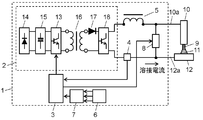
- FIG. 1 is a diagram illustrating a schematic configuration of an arc welding apparatus according to Embodiment 1 of the present invention.
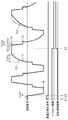
- FIG. 2 is a diagram showing a time change of the welding current waveform in the first embodiment of the present invention.
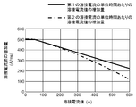
- FIG. 3 is a diagram showing a correlation between the welding current value and the increase amount of the welding current value per unit time of the welding current in the first embodiment of the present invention.
- FIG. 4 is a diagram showing a schematic configuration of a conventional arc welding apparatus.
- FIG. 5 is a diagram showing a time change of a welding current waveform in a conventional arc welding apparatus.
- FIG. 1 is a diagram showing a schematic configuration of an arc welding apparatus in the present embodiment
- FIG. 2 is a diagram showing a time change of a welding current waveform in the present embodiment
- FIG. 3 is a diagram showing a correlation between the welding current value and the increase amount of the welding current value per unit time of the welding current in the present embodiment.
- non-consumable electrode type AC arc welding apparatus that performs welding by alternately repeating a reverse polarity period and a positive polarity period will be described as an example.
- an arc welding apparatus 1 includes an output unit 2 that performs welding output, a control unit 3, a current detection unit 4 that detects a welding current, a reactor 5 that smoothes the output of the output unit 2, and a storage unit 6. And a selection unit 7 for selecting the storage contents of the storage unit 6 and a high voltage generation unit 8 for outputting a high voltage.
- the control unit 3 controls the output unit 2 by outputting a control signal to the output unit 2 every control cycle.
- the storage unit 6 stores an increase amount of the welding current value per unit time of the welding current with respect to the welding current value.
- the output unit 2 includes a rectification unit 14, a smoothing unit 15, an inverter control unit 13, a transformer 16, a secondary rectification unit 17, and a secondary inverter control unit 18.
- the smoothing unit 15 smoothes the output of the rectifying unit 14.
- the inverter control unit 13 performs inverter control on the output of the smoothing unit 15.
- the transformer 16 transforms the output of the inverter control unit 13.
- the secondary rectifier 17 smoothes the output of the transformer 16.
- the secondary inverter control unit 18 performs inverter control on the output of the secondary rectification unit 17.
- the arc welding apparatus 1 is connected to a welding torch 10 provided with an electrode 9 and a base material 12 as a welding object via cables 10a and 12a. Then, the arc welding apparatus 1 performs welding by generating an arc 11 between the electrode 9 and the base material 12 by supplying electric power between the electrode 9 and the base material 12.
- IP indicates the peak current value of the welding current
- IS indicates the start current value of the welding current
- I1 is a current value during the rise, indicating a first current value smaller than the peak current IP
- I2 is a current value during the fall, indicating a second current value smaller than the peak current IP.
- TUP1 indicates a first rise time that is a time from when the welding current reaches zero to the start current IS, and TUP2 reaches the peak current IP from when the welding current commutates to zero.
- the 2nd rise time which is time until is shown.
- TDN1 indicates a first fall time that is a time until the peak current IP decreases to the second current value I2, and TH indicates a predetermined time that is a period during which the second current value I2 is maintained.
- TDN2 indicates a second fall time that is a time obtained by adding the first fall time TDN1 and the predetermined time TH.
- DI1 indicates an increase amount of the welding current value per unit time of the first welding current
- DI2 indicates an increase of the welding current value per unit time of the second welding current different from the first welding current. Indicates the amount.
- E1 indicates a welding start time that is a time when welding is started
- E2 indicates a current detection time that is a time when current is detected
- E3 indicates an arc start completion time that is a time when the arc start period is completed. Is shown.
- a commercial power input for example, 200 V
- an external device such as a switchboard
- the output unit 2 of the arc welding apparatus 1 is fed to the output unit 2 of the arc welding apparatus 1.
- the rectifying unit 14 constituted by a diode or the like
- the smoothing unit 15 constituted by an electrolytic capacitor or the like.
- the current detection part 4 comprised by CT (Current Transformer) etc. detects a welding current.
- the output of the current detection unit 4 is input to the control unit 3 including a CPU, a DSP (Digital Signal Processor), an ADC (Analog to Digital Converter), and the like.
- CT Current Transformer
- control unit 3 creates an output command suitable for welding in synchronization with the control timing of the inverter (for example, the switching operation timing of the inverter), performs current feedback calculation based on the output target, and performs switching of the inverter control unit 13.
- the conduction width of the element is calculated and a welding current control signal is output.
- an IGBT Insulated Gate Bipolar Transistor
- MOSFET Metal-Oxide Semiconductor Field Transistor, etc.
- PWM Pulse Width Modulation
- the transformer 16 operates at 40 kHz as an inverter frequency.
- the inverter includes an IGBT and a transformer, and operates at a transformer current frequency of 40 kHz.
- the high-frequency AC voltage output from the transformer 16 is rectified by the secondary rectification unit 17 configured by a diode or the like and input to the secondary inverter control unit 18.
- the secondary inverter control unit 18 is configured by a circuit such as a full bridge or a half bridge using an IGBT or the like, and switches output polarity between positive polarity and reverse polarity.
- the positive polarity means a case where the moving direction of electrons in the arc plasma is a direction from the electrode 9 toward the base material 12, the electrode 9 is negative, and the base material is positive.
- Reverse polarity refers to the case where the moving direction of electrons in the arc plasma is the direction from the base material 12 toward the electrode 9, the electrode 9 is positive, and the base material 12 is negative.
- the welding current and welding voltage output from the secondary inverter control unit 18 are smoothed through the reactor 5 and supplied to the welding torch 10. Then, an arc 11 is generated between the tip of the electrode 9 made of tungsten, which is a non-consumable electrode, and the base material 12, which is a welding object such as an aluminum material, and AC arc welding is performed.
- the inductance value of the reactor 5 is 100 ⁇ H or less, for example, 50 ⁇ H, and the inductance value is smaller than that of the reactor 21 provided in the conventional arc welding apparatus 22 described with reference to FIG. Thereby, the increase amount of the welding current value per unit time of the welding current can be set to 1500 A / msec.
- storage part 6 comprised with CPU etc. is the per unit time of the 1st welding current shown in FIG. 3 as an increase amount of the welding current value per unit time of a different welding current with respect to the same welding current value.
- the increase amount of the welding current and the increase amount of the welding current per unit time of the second welding current are stored. It should be noted that the increase amount of the welding current per unit time of the welding current may be stored not three but three or more.
- the selection part 7 comprised by CPU etc. is the increase amount of the welding current value per unit time of one welding current from the increase amount of the welding current value per unit time of the some welding current memorize
- the selection unit 7 may be switched automatically according to welding current setting, frequency setting, and welding method setting. Or you may make it switch manually according to the liking of the operator who operates the arc welding apparatus 1. FIG.
- the control unit 3 performs output control by outputting a control signal to the output unit based on the increase amount of the welding current value per unit time of the welding current selected and output by the selection unit 7. Further, the control unit 3 can also output a high voltage generation signal to the high voltage generation unit 8, and when the arc start is started by pressing a torch switch (not shown) provided in the welding torch 10, the high voltage generation signal is output. Turn on and output to high voltage generator 8. Then, an arc is generated between the electrode 9 and the base material 12 due to the high voltage output from the high voltage generator 8, and a current flows. When a current detection signal is received from the current detector 4 that detects this current, The voltage generation signal is turned off, and the output of the high voltage generator 8 is stopped.
- the high voltage generation unit 8 composed of a flyback transformer or the like applies a voltage (for example, 15 kV) higher than the voltage during steady welding to the electrode 9 and the mother. Applied between the material 12.
- the high voltage generation signal output from the control unit 3 is off, the application of the high voltage is stopped.
- the control unit 3 turns on the drive of the inverter control unit 13 and applies a no-load voltage (for example, 80 V) between the electrode 9 and the base material 12. Further, the control unit 3 applies a high voltage (for example, 15 kV) for arc start between the electrode 9 and the base material 12 by turning on the high voltage generation signal and outputting it to the high voltage generation unit 8. To do. Then, at the current detection time point E2 when the arc is generated by this high voltage and a welding current flows and the current detection unit 4 detects the current, the control unit 3 turns off the high voltage generation signal and generates a high voltage. By outputting to the unit 8, the application of the high voltage is stopped.
- a no-load voltage for example, 80 V
- a high voltage for example, 15 kV
- the welding current rises at an increase in the welding current per unit time of 1500 A / msec, and the start current value IS (for example, 350A).
- the completion of the arc start period may be the time when a preset time (for example, 100 msec) has elapsed since the arc start.
- the completion of the arc start period may be the time when, for example, five pulses of AC output are performed when the number of times of output of AC pulses is measured and the pulses are output a predetermined number of times.
- the welding current is a second rise time TUP2 (for example, 0.85 msec from the zero crossing point when the polarity of the welding current is commutated).
- the peak current IP for example, 350 A
- the welding current rises with an increase amount of the welding current per unit time being 500 A / ms until it reaches the first current value I1 (for example, 50 A). And after exceeding 1st electric current value I1 (for example, 50A), it is smaller than 500 A / msec, and the increase amount of the welding current value per unit time becomes so small that the absolute value of welding current becomes high. stand up.
- the absolute value of the welding current is based on the increase amount of the welding current per unit time of the first welding current indicated by a solid line in FIG.
- the welding current is sharply raised by the rise of the welding current depending on the inductance value of the reactor 5 to ensure the arc start performance.
- the filler wire workability is improved by giving a welding current command and controlling so that the rise of the welding current becomes gentler than that at the time of arc start during steady welding without depending on the inductance value of the reactor 5. Can be.
- the amount of increase in the welding current per unit time rises at 1500 A / msec instead of 500 A / msec until the first current value I1 (for example, 50 A) is reached.
- the control may be performed such that the increase in the welding current value per unit time decreases as the absolute value of the welding current increases.
- 1500 A / msec is assumed to be the maximum amount of change per unit time that can be output by the arc welding apparatus 1 determined by the inductance value of the reactor 5.
- the welding current may be increased by the maximum amount of change per unit time in the initial period of increase in current.
- the arc welding apparatus 1 of the present invention is a non-consumable electrode type arc welding apparatus that performs welding by outputting an AC pulse having an absolute value of a peak current of 300 A or more and 1500 A or less.
- the arc welding apparatus 1 includes an output unit 2 that outputs a welding current, a control unit 3 that outputs a welding current control signal for each cycle of the welding current to be controlled, and an inductance value of 10 ⁇ H.
- the reactor 5 is 100 ⁇ H or less.
- the control unit 3 of the arc welding apparatus 1 uses the first rise time TUP1 and the second rise time TUP2 to perform welding so that the second rise time TUP2 is longer than the first rise time TUP1. The current is controlled.
- the first rise time TUP1 is the time from when the welding current starts the arc start until the absolute value of the peak current is reached at the time of the arc start.
- the second rise time TUP2 is the time from the zero cross point when the polarity of the welding current commutates during steady welding after the arc start until the absolute value of the peak current is reached.
- an arc welding apparatus 1 that improves arc start performance during large-current construction, does not deteriorate workability in the work of inserting a filler wire, and enables good workability to melt the filler wire smoothly. can do.
- control unit 3 may be configured to control the welding current that increases during the second rise time TUP2 such that the increase in the welding current value per unit time decreases as the absolute value of the welding current increases.
- controller 3 increases the welding current that increases during the second rise time TUP2 without changing the increase in the welding current value per unit time until the first current value I1 is reached.
- the control may be performed such that the increase in the welding current value per unit time decreases as the absolute value of the welding current increases.
- the welding current is sharply raised by the rise of the welding current depending on the inductance value of the reactor 5 to ensure the arc start performance, and at the time of steady welding, the workability of the filler wire is improved. Can be good.
- the output section can output a welding current of 1000 A / msec or more and 10,000 A / msec or less as an increase amount of the welding current per unit time.
- the increase amount of the welding current per unit time at the first rise time TUP1 is 1000 A / ms or more and 10000 A / msec or less
- the increase amount of the welding current per unit time at the second rise time TUP2 is 10 A. / Msec or more and 500 A / msec or less.
- the welding current is sharply raised by the rise of the welding current depending on the inductance value of the reactor 5 to ensure the arc start performance, and at the time of steady welding, the workability of the filler wire is improved. Can be good.
- the output section can output a welding current of 1000 A / msec or more and 10,000 A / msec or less as an increase amount of the welding current per unit time.
- the increase amount of the welding current per unit time in 1st rise time TUP1 is 1000 A / msec or more and 10000 A / msec or less.
- the amount of increase in the welding current per unit time until reaching the first current value I1 during the second rise time TUP2 is 1000 A / msec or more and 10000 A / msec or less.
- the increase amount of the welding current per unit time when the first current value I1 during the second rise time TUP2 is exceeded may be 10 A / msec or more and 500 A / msec or less.
- the welding current is sharply raised by the rise of the welding current depending on the inductance value of the reactor 5 to ensure the arc start performance, and at the time of steady welding, the workability of the filler wire is improved. Can be good.
- the output unit 2 may include an inverter control unit 13, and the inverter frequency of the inverter control unit 13 may be 40 kHz or more and 1 MHz or less.
- a high voltage generator 8 is provided between the non-consumable electrode and the welding object between the non-consumable electrode and the welding object.
- a configuration may be adopted in which an arc start is performed by applying a high voltage.
- This configuration makes it possible to achieve a better arc start and does not damage the base material and the electrode during the arc start.
- the control unit 3 reduces the welding current during steady welding from the peak current value IP (for example, 350 A) to the second current value I2 (for example, 100 A) at a welding current reduction amount of 800 A / msec per unit time.
- the second current value I2 is controlled to be commutated after being maintained for a predetermined time (for example, 0.1 msec). Note that the first fall time TDN1 (for example, 0.32 msec) until the peak current value IP is reduced to the second current value I2 is shorter than the second rise time TUP2 (for example, 0.85 msec). Control to be.
- a second falling time TDN2 (for example, 0.42 msec) from when the welding current starts to decrease from the peak welding current IP to when the zero crossing point when the polarity of the welding current commutates is reached.
- Control may be performed so as to be shorter than the second rise time TUP2.
- the second current value I2 which is the current value before commutation, is increased by increasing the amount of decrease in the current fall, and the commutation in the conventional arc welding apparatus 22 described with reference to FIG. It can be set lower than the previous current value I3 (for example, 200 A). Thereby, it is possible to prevent the semiconductor element from being damaged by a high surge voltage generated due to switching of the semiconductor constituting the secondary inverter at the time of commutation.
- the current value I3 before commutation of the conventional arc welding apparatus 22 described with reference to FIG. 5 is determined by the inductance value of the reactor 21 shown in FIG. 4, and is determined by the amount of decrease in the current fall. Therefore, the current could not be dropped sharply before commutation.
- the storage unit 6 of the arc welding apparatus 1 stores the welding current per unit time of the first welding current shown in FIG. 3 as an increase amount of the welding current value per unit time of different welding currents for the same welding current value. And an increase amount of the welding current per unit time of the second welding current are stored. And the selection part 7 switches and selects the memory content of the memory
- the selection unit 7 selects the increase amount of the welding current per unit time of the first welding current. At this time, the rise of the welding current during the second rise time TUP2 rises with a slope indicated by the increase amount DI1 of the welding current per unit time of the first welding current shown in FIG. On the other hand, consider a case where the selection unit 7 selects the amount of increase in the welding current per unit time of the second welding current. At this time, the rise of the welding current during the second rise time TUP2 rises with a slope of the increase amount DI2 of the welding current per unit time of the second welding current shown in FIG.
- the degree of decrease in the increase amount of the welding current per unit time of the second welding current is larger than the increase amount of the welding current per unit time of the first welding current. From this, it can be seen that the welding current of the increasing amount DI2 of the welding current per unit time of the second welding current in FIG. 2 rises more gently. When the rising waveform of the welding current becomes gentle, the arc spreads and the workability of the filler wire is improved. On the other hand, it tends to be difficult for fillet welding due to concentration. Therefore, it is desirable to memorize each suitable rise based on the welding object, welding conditions, etc., and to perform welding by selecting the suitable rise.
- the control unit 3 reduces the welding current at the time of steady welding from the peak current value IP to the second current value I2 smaller than the peak current value IP, and this second current value I2. Is controlled to commutate after maintaining TH for a predetermined time.
- the control unit 3 is configured to control the first fall time TDN1 until the peak current value IP is reduced to the second current value I2 to be shorter than the second rise time TUP2.
- the second current value I2 which is the current value before commutation, can be set lower than the current value I3 before commutation in the conventional arc welding apparatus 22. .
- the semiconductor element from being damaged by a high surge voltage generated due to switching of the semiconductor constituting the secondary inverter at the time of commutation.
- the second current value I2 which is the current value before commutation, can be set lower than the current value I3 before commutation in the conventional arc welding apparatus 22. .
- the semiconductor element from being damaged by a high surge voltage generated due to switching of the semiconductor constituting the secondary inverter at the time of commutation.
- the second current value I2 which is the current value before commutation, can be set lower than the current value I3 before commutation in the conventional arc welding apparatus 22. .
- the semiconductor element from being damaged by a high surge voltage generated due to switching of the semiconductor constituting the secondary inverter at the time of commutation.
- the peak current value IP has been described as the same value on the positive polarity side and the reverse polarity side, but may be different values.
- the decrease curve of the current increase amount as shown in FIG. 3 may be decreased linearly (primary expression) or nonlinearly according to a polynomial (for example, quadratic expression).
- the lower limit may be set (set a minimum value) with an arbitrary value (for example, 50 A / msec), and if necessary, an intermediate point may be provided to bend the degradation characteristic nonlinearly.
- the start current value IS and the peak current value IP have been described as being the same value, but may be different values.
- AC arc welding has been described in the present embodiment, it may be applied to a pulse rising waveform in DC non-consumable electrode type arc welding.
- the increase amount of the welding current per unit time of the welding current at the time of the rise of the welding current is different in this embodiment, although the same decrease curve is used on the positive polarity side and the reverse polarity side. You may make it use a characteristic.
- the increase amount of the welding current per unit time of the welding current at the time of rising of the welding current has been described with reference to FIG. 2 as an example of switching during welding, but is set before the arc start and fixed during welding. May be.
- the peak current value of the positive polarity and the reverse polarity has been described as an arbitrary fixed value in FIG. 2, but may be a welding current waveform that fluctuates during the peak period.
- the second rise time is the first rise time.
- the welding current is controlled to be longer than the time. This control can provide an arc welding apparatus that has good workability without deteriorating workability in the work of inserting the filler wire even during large current construction.
- the present invention can provide an arc welding apparatus having good workability without deteriorating workability in the work of inserting a filler wire even during large current construction.
- the arc welding apparatus of the present invention is industrially useful as an arc welding apparatus in an industry that performs arc welding construction, for example, a large-sized aluminum member such as the plant construction industry, which is welded at a large current and produced. It is.
Landscapes
- Engineering & Computer Science (AREA)
- Physics & Mathematics (AREA)
- Plasma & Fusion (AREA)
- Mechanical Engineering (AREA)
- Arc Welding Control (AREA)
- Generation Of Surge Voltage And Current (AREA)
Abstract
Description
図1は本実施の形態におけるアーク溶接装置の概略構成を示す図であり、図2は本実施の形態における溶接電流波形の時間変化を示す図である。図3は本実施の形態における溶接電流値と溶接電流の単位時間当たりの溶接電流値の増加量の相関を示す図である。図1のように構成されたアーク溶接装置について、図2と図3を用いてその動作を説明する。

2 出力部
3 制御部
4 電流検出部
5 リアクトル
6 記憶部
7 選択部
8 高電圧発生部
9 電極
10 溶接トーチ
10a,12a ケーブル
11 アーク
12 母材
13 インバータ制御部
14 整流部
15 平滑部
16 変圧器
17 2次整流部
18 2次インバータ制御部
Claims (11)
- ピーク電流の絶対値が、300A以上、1500A以下である交流パルスを出力して溶接を行う非消耗電極式のアーク溶接装置であって、
溶接電流を出力する出力部と、
前記出力部に対して、制御する前記溶接電流の周期毎に溶接電流制御信号を出力する制御部と、
インダクタンス値が、10μH以上、100μH以下であるリアクトルと、を備え、
前記制御部は、アークスタート時において、前記溶接電流がアークスタートを開始してからピーク電流の絶対値に達するまでの第1の立ち上がり時間と、アークスタート後の定常溶接時に前記溶接電流の極性が転流する際のゼロクロス時点からピーク電流の絶対値に達するまでの第2の立ち上がり時間と、を用いて、前記第2の立ち上がり時間が前記第1の立ち上がり時間よりも長くなるように前記溶接電流を制御するアーク溶接装置。 - 前記制御部は、前記第2の立ち上がり時間中に増加する前記溶接電流を、前記溶接電流の絶対値が高くなるほど単位時間当たりの溶接電流値の増加が少なくなるように制御する請求項1記載のアーク溶接装置。
- 前記制御部は、前記第2の立ち上がり時間中に増加する前記溶接電流を、第1の電流値になるまでは前記単位時間当たりの溶接電流値の増加を変更せずに増加し、前記第1の電流値を超えた場合には、前記溶接電流の絶対値が高くなるほど前記単位時間当たりの溶接電流値の増加が少なくなるように制御する請求項2記載のアーク溶接装置。
- 前記出力部は、単位時間あたりの溶接電流の増加量として1000A/msec以上、10000A/msec以下の溶接電流の出力が可能であり、前記第1の立ち上がり時間における単位時間あたりの溶接電流の増加量は1000A/ms以上、10000A/msec以下であり、前記第2の立ち上がり時間における単位時間あたりの溶接電流の増加量は、10A/msec以上、500A/msec以下である請求項1記載のアーク溶接装置。
- 前記出力部は、単位時間あたりの溶接電流の増加量として1000A/msec以上、10000A/msec以下の溶接電流の出力が可能であり、第1の立ち上がり時間における単位時間あたりの溶接電流の増加量は1000A/msec以上、10000A/msec以下であり、第2の立ち上がり時間中の前記第1の電流値になるまでにおける単位時間あたりの溶接電流の増加量は1000A/msec以上、10000A/msec以下であり、第2の立ち上がり時間中の前記第1の電流値を超えた場合における単位時間あたりの溶接電流の増加量は、10A/msec以上、500A/msec以下である請求項3記載のアーク溶接装置。
- 前記制御部は、定常溶接時の溶接電流をピーク電流値から前記ピーク電流値よりも小さい第2の電流値まで減少して、この第2の電流値を所定時間維持した後に転流するように制御し、前記ピーク電流値から前記第2の電流値に低減するまでの第1の立ち下がり時間を、前記第2の立ち上がり時間よりも短くなるように制御する請求項1記載のアーク溶接装置。
- 前記制御部は、定常溶接時に溶接電流をピーク溶接電流から溶接電流の極性が転流する際のゼロクロス時点に達するまでの第2の立ち下がり時間を、前記第2の立ち上がり時間よりも短くなるように制御する請求項1記載のアーク溶接装置。
- 前記出力部は、単位時間あたりの溶接電流の減少量として800A/msec以上、10000A/msec以下の溶接電流の減少が可能であり、前記第1の立ち下がり時間における単位時間あたりの溶接電流の減少量、または、前記第2の立ち下がり時間における単位時間あたりの溶接電流の減少量は、800A/ms以上、10000A/msec以下である請求項6または7のいずれか1項に記載のアーク溶接装置。
- 同一の溶接電流値に対して異なる溶接電流の単位時間当たりの溶接電流値の増加量を複数記憶する記憶部と、前記記憶部に記憶した複数の溶接電流の単位時間当たりの溶接電流値の増加量から1つの溶接電流の単位時間当たりの溶接電流値の増加量を選択する選択部と、を備えた請求項1に記載のアーク溶接装置。
- 前記出力部はインバータ制御部を備え、前記インバータ制御部のインバータ周波数は、40kHz以上、1MHz以下である請求項1記載のアーク溶接装置。
- アークスタート時に非消耗電極と溶接対象物との間に定常溶接時の電圧よりも高い高電圧を印加するための高電圧発生部を備え、前記非消耗電極と前記溶接対象物との間に高電圧を印加してアークスタートを行う請求項1記載のアーク溶接装置。
Priority Applications (2)
| Application Number | Priority Date | Filing Date | Title |
|---|---|---|---|
| CN201180002638.3A CN102470473B (zh) | 2010-03-18 | 2011-03-14 | 电弧焊接装置 |
| JP2012505493A JP5293882B2 (ja) | 2010-03-18 | 2011-03-14 | アーク溶接装置 |
Applications Claiming Priority (2)
| Application Number | Priority Date | Filing Date | Title |
|---|---|---|---|
| JP2010062355 | 2010-03-18 | ||
| JP2010-062355 | 2010-03-18 |
Publications (1)
| Publication Number | Publication Date |
|---|---|
| WO2011114679A1 true WO2011114679A1 (ja) | 2011-09-22 |
Family
ID=44648794
Family Applications (1)
| Application Number | Title | Priority Date | Filing Date |
|---|---|---|---|
| PCT/JP2011/001450 Ceased WO2011114679A1 (ja) | 2010-03-18 | 2011-03-14 | アーク溶接装置 |
Country Status (3)
| Country | Link |
|---|---|
| JP (1) | JP5293882B2 (ja) |
| CN (1) | CN102470473B (ja) |
| WO (1) | WO2011114679A1 (ja) |
Cited By (6)
| Publication number | Priority date | Publication date | Assignee | Title |
|---|---|---|---|---|
| JP2014184466A (ja) * | 2013-03-22 | 2014-10-02 | Osaka Univ | パルスアーク溶接方法 |
| WO2015036819A1 (en) * | 2013-09-16 | 2015-03-19 | Lincoln Global, Inc. | Tig welding system |
| WO2018079345A1 (ja) * | 2016-10-24 | 2018-05-03 | 株式会社ダイヘン | 交流パルスアーク溶接制御方法 |
| WO2018034890A3 (en) * | 2016-08-16 | 2018-05-11 | Illinois Tool Works Inc. | Welding-type power supplies with adjustable ac current commutation thresholds |
| US10610945B2 (en) | 2012-10-01 | 2020-04-07 | Panasonic Intellectual Property Management Co., Ltd. | Arc welding control method |
| WO2025211275A1 (ja) * | 2024-04-01 | 2025-10-09 | パナソニックIpマネジメント株式会社 | 溶接電流波形の修正方法及びプログラム |
Families Citing this family (31)
| Publication number | Priority date | Publication date | Assignee | Title |
|---|---|---|---|---|
| US10040143B2 (en) | 2012-12-12 | 2018-08-07 | Illinois Tool Works Inc. | Dabbing pulsed welding system and method |
| US10906114B2 (en) | 2012-12-21 | 2021-02-02 | Illinois Tool Works Inc. | System for arc welding with enhanced metal deposition |
| US10065260B2 (en) * | 2013-01-03 | 2018-09-04 | Illinois Tool Works Inc. | System and method for controlling an arc welding process |
| US9950383B2 (en) | 2013-02-05 | 2018-04-24 | Illinois Tool Works Inc. | Welding wire preheating system and method |
| US10835983B2 (en) | 2013-03-14 | 2020-11-17 | Illinois Tool Works Inc. | Electrode negative pulse welding system and method |
| US11045891B2 (en) | 2013-06-13 | 2021-06-29 | Illinois Tool Works Inc. | Systems and methods for anomalous cathode event control |
| US10828728B2 (en) | 2013-09-26 | 2020-11-10 | Illinois Tool Works Inc. | Hotwire deposition material processing system and method |
| US11154946B2 (en) | 2014-06-30 | 2021-10-26 | Illinois Tool Works Inc. | Systems and methods for the control of welding parameters |
| US11198189B2 (en) | 2014-09-17 | 2021-12-14 | Illinois Tool Works Inc. | Electrode negative pulse welding system and method |
| US11478870B2 (en) | 2014-11-26 | 2022-10-25 | Illinois Tool Works Inc. | Dabbing pulsed welding system and method |
| US10189106B2 (en) | 2014-12-11 | 2019-01-29 | Illinois Tool Works Inc. | Reduced energy welding system and method |
| US11370050B2 (en) | 2015-03-31 | 2022-06-28 | Illinois Tool Works Inc. | Controlled short circuit welding system and method |
| US11285559B2 (en) | 2015-11-30 | 2022-03-29 | Illinois Tool Works Inc. | Welding system and method for shielded welding wires |
| US10610946B2 (en) | 2015-12-07 | 2020-04-07 | Illinois Tool Works, Inc. | Systems and methods for automated root pass welding |
| US10675699B2 (en) | 2015-12-10 | 2020-06-09 | Illinois Tool Works Inc. | Systems, methods, and apparatus to preheat welding wire |
| US12194579B2 (en) | 2015-12-10 | 2025-01-14 | Illinois Tool Works Inc. | Systems, methods, and apparatus to preheat welding wire |
| US10766092B2 (en) | 2017-04-18 | 2020-09-08 | Illinois Tool Works Inc. | Systems, methods, and apparatus to provide preheat voltage feedback loss protection |
| US10870164B2 (en) | 2017-05-16 | 2020-12-22 | Illinois Tool Works Inc. | Systems, methods, and apparatus to preheat welding wire |
| WO2018220933A1 (ja) * | 2017-05-29 | 2018-12-06 | パナソニックIpマネジメント株式会社 | アーク加工用電源装置およびアーク加工用電源装置の制御方法 |
| CN111386168A (zh) | 2017-06-09 | 2020-07-07 | 伊利诺斯工具制品有限公司 | 具有两个接触焊嘴和用于冷却并传导电流的制冷主体的用于焊接炬的焊接组装件 |
| EP3634684B1 (en) | 2017-06-09 | 2022-10-05 | Illinois Tool Works Inc. | Welding torch with a first contact tip to preheat welding wire and a second contact tip |
| CN111315524A (zh) | 2017-06-09 | 2020-06-19 | 伊利诺斯工具制品有限公司 | 具有两个触头和用于将电流传导至触头的多个液冷组件的焊接炬 |
| US11524354B2 (en) | 2017-06-09 | 2022-12-13 | Illinois Tool Works Inc. | Systems, methods, and apparatus to control weld current in a preheating system |
| US11590598B2 (en) | 2017-06-09 | 2023-02-28 | Illinois Tool Works Inc. | Systems, methods, and apparatus to preheat welding wire |
| US11020813B2 (en) | 2017-09-13 | 2021-06-01 | Illinois Tool Works Inc. | Systems, methods, and apparatus to reduce cast in a welding wire |
| CN113165097B (zh) | 2018-08-31 | 2023-11-03 | 伊利诺斯工具制品有限公司 | 用于电阻式地预加热电极丝的埋弧焊系统和埋弧焊焊炬 |
| US11014185B2 (en) | 2018-09-27 | 2021-05-25 | Illinois Tool Works Inc. | Systems, methods, and apparatus for control of wire preheating in welding-type systems |
| EP3898055A2 (en) | 2018-12-19 | 2021-10-27 | Illinois Tool Works, Inc. | Contact tip, wire preheating assembly, contact tip assembly and consumable electrode-fed welding type system |
| US12583048B2 (en) | 2019-03-29 | 2026-03-24 | Illinois Tool Works Inc. | Methods and apparatus to convert welding-type power to welding-type power and resistive preheating power |
| US12103121B2 (en) | 2019-04-30 | 2024-10-01 | Illinois Tool Works Inc. | Methods and apparatus to control welding power and preheating power |
| US11772182B2 (en) | 2019-12-20 | 2023-10-03 | Illinois Tool Works Inc. | Systems and methods for gas control during welding wire pretreatments |
Citations (5)
| Publication number | Priority date | Publication date | Assignee | Title |
|---|---|---|---|---|
| JPS569065A (en) * | 1979-07-03 | 1981-01-29 | Osaka Denki Kk | Electric power source device for alternating current arc welding |
| JPS61249672A (ja) * | 1985-04-27 | 1986-11-06 | Sansha Electric Mfg Co Ltd | 交流アーク溶接用電源装置 |
| JPH08300156A (ja) * | 1995-04-28 | 1996-11-19 | Origin Electric Co Ltd | 交流プラズマアーク溶接機 |
| JP2000254779A (ja) * | 1999-03-08 | 2000-09-19 | Daihen Corp | 交流パルスアーク溶接方法及び溶接装置 |
| JP2001030072A (ja) * | 1999-07-16 | 2001-02-06 | Daihen Corp | 交流アーク溶接電源制御方法及び電源装置 |
Family Cites Families (2)
| Publication number | Priority date | Publication date | Assignee | Title |
|---|---|---|---|---|
| JP3844004B1 (ja) * | 2005-05-31 | 2006-11-08 | 松下電器産業株式会社 | パルスアーク溶接制御方法及びパルスアーク溶接装置 |
| WO2008105116A1 (ja) * | 2007-02-28 | 2008-09-04 | Panasonic Corporation | 溶接出力制御方法およびアーク溶接装置 |
-
2011
- 2011-03-14 CN CN201180002638.3A patent/CN102470473B/zh active Active
- 2011-03-14 WO PCT/JP2011/001450 patent/WO2011114679A1/ja not_active Ceased
- 2011-03-14 JP JP2012505493A patent/JP5293882B2/ja active Active
Patent Citations (5)
| Publication number | Priority date | Publication date | Assignee | Title |
|---|---|---|---|---|
| JPS569065A (en) * | 1979-07-03 | 1981-01-29 | Osaka Denki Kk | Electric power source device for alternating current arc welding |
| JPS61249672A (ja) * | 1985-04-27 | 1986-11-06 | Sansha Electric Mfg Co Ltd | 交流アーク溶接用電源装置 |
| JPH08300156A (ja) * | 1995-04-28 | 1996-11-19 | Origin Electric Co Ltd | 交流プラズマアーク溶接機 |
| JP2000254779A (ja) * | 1999-03-08 | 2000-09-19 | Daihen Corp | 交流パルスアーク溶接方法及び溶接装置 |
| JP2001030072A (ja) * | 1999-07-16 | 2001-02-06 | Daihen Corp | 交流アーク溶接電源制御方法及び電源装置 |
Cited By (12)
| Publication number | Priority date | Publication date | Assignee | Title |
|---|---|---|---|---|
| US10610945B2 (en) | 2012-10-01 | 2020-04-07 | Panasonic Intellectual Property Management Co., Ltd. | Arc welding control method |
| JP2014184466A (ja) * | 2013-03-22 | 2014-10-02 | Osaka Univ | パルスアーク溶接方法 |
| WO2015036819A1 (en) * | 2013-09-16 | 2015-03-19 | Lincoln Global, Inc. | Tig welding system |
| US9481045B2 (en) | 2013-09-16 | 2016-11-01 | Lincoln Global, Inc. | TIG welding system |
| WO2018034890A3 (en) * | 2016-08-16 | 2018-05-11 | Illinois Tool Works Inc. | Welding-type power supplies with adjustable ac current commutation thresholds |
| CN109562480A (zh) * | 2016-08-16 | 2019-04-02 | 伊利诺斯工具制品有限公司 | 具有可调整ac电流换向阈值的焊接型电力供应器 |
| CN109562480B (zh) * | 2016-08-16 | 2022-07-22 | 伊利诺斯工具制品有限公司 | 具有可调整ac电流换向阈值的焊接型电力供应器 |
| US12263545B2 (en) | 2016-08-16 | 2025-04-01 | Illinois Tool Works Inc. | Welding-type power supplies with adjustable AC current commutation thresholds |
| WO2018079345A1 (ja) * | 2016-10-24 | 2018-05-03 | 株式会社ダイヘン | 交流パルスアーク溶接制御方法 |
| JPWO2018079345A1 (ja) * | 2016-10-24 | 2019-09-12 | 株式会社ダイヘン | 交流パルスアーク溶接制御方法 |
| US12005530B2 (en) | 2016-10-24 | 2024-06-11 | Daihen Corporation | AC pulse arc welding control method |
| WO2025211275A1 (ja) * | 2024-04-01 | 2025-10-09 | パナソニックIpマネジメント株式会社 | 溶接電流波形の修正方法及びプログラム |
Also Published As
| Publication number | Publication date |
|---|---|
| JPWO2011114679A1 (ja) | 2013-06-27 |
| CN102470473B (zh) | 2014-07-02 |
| CN102470473A (zh) | 2012-05-23 |
| JP5293882B2 (ja) | 2013-09-18 |
Similar Documents
| Publication | Publication Date | Title |
|---|---|---|
| JP5293882B2 (ja) | アーク溶接装置 | |
| EP2732901B1 (en) | Arc welding control method and arc welding device | |
| CN101687268B (zh) | 焊接电源 | |
| JP2019104040A (ja) | 被覆アーク溶接システム、および、被覆アーク溶接用の溶接電源装置 | |
| JP5506590B2 (ja) | アーク溶接機 | |
| KR102149744B1 (ko) | 복합용접기 | |
| JP6417545B2 (ja) | 溶接装置 | |
| JP2017011870A (ja) | Dc/dcコンバータ | |
| JP7106799B2 (ja) | 溶接電源装置 | |
| JP5877316B2 (ja) | 交流アーク溶接装置 | |
| JP2019084576A (ja) | 溶接電源装置 | |
| JP5584101B2 (ja) | アーク加工用電源装置 | |
| JP5353663B2 (ja) | インバータ制御方法およびインバータ制御加工装置 | |
| JP2019205264A (ja) | 溶接用電源装置および出力制御方法。 | |
| KR100907651B1 (ko) | 저항 용접기용 정전력 제어장치 및 방법 | |
| JP5429362B2 (ja) | 交流tig溶接方法 | |
| JP4570444B2 (ja) | アーク溶接装置 | |
| JP2019089093A (ja) | 溶接電源装置 | |
| JP7142313B2 (ja) | 溶接電源装置 | |
| JP2026059066A (ja) | サブマージアーク溶接制御方法及びサブマージアーク溶接装置 | |
| JP5278563B2 (ja) | Tig溶接方法 | |
| WO2018186098A1 (ja) | 被覆アーク溶接システム、および、被覆アーク溶接用の溶接電源装置 | |
| JP2011240347A (ja) | アーク加工用電源装置 | |
| JP2006281257A (ja) | インバータ制御による消耗電極式のアーク溶接電源およびその制御方法 | |
| JP2019042754A (ja) | パルスアーク溶接制御方法 |
Legal Events
| Date | Code | Title | Description |
|---|---|---|---|
| WWE | Wipo information: entry into national phase |
Ref document number: 201180002638.3 Country of ref document: CN |
|
| 121 | Ep: the epo has been informed by wipo that ep was designated in this application |
Ref document number: 11755872 Country of ref document: EP Kind code of ref document: A1 |
|
| WWE | Wipo information: entry into national phase |
Ref document number: 4865/KOLNP/2011 Country of ref document: IN |
|
| WWE | Wipo information: entry into national phase |
Ref document number: 2012505493 Country of ref document: JP |
|
| NENP | Non-entry into the national phase |
Ref country code: DE |
|
| 122 | Ep: pct application non-entry in european phase |
Ref document number: 11755872 Country of ref document: EP Kind code of ref document: A1 |