WO2011111583A1 - 受信装置、受信方法、受信プログラム、及びプロセッサ - Google Patents
受信装置、受信方法、受信プログラム、及びプロセッサ Download PDFInfo
- Publication number
- WO2011111583A1 WO2011111583A1 PCT/JP2011/054754 JP2011054754W WO2011111583A1 WO 2011111583 A1 WO2011111583 A1 WO 2011111583A1 JP 2011054754 W JP2011054754 W JP 2011054754W WO 2011111583 A1 WO2011111583 A1 WO 2011111583A1
- Authority
- WO
- WIPO (PCT)
- Prior art keywords
- signal
- unit
- replica
- time
- fft
- Prior art date
- Legal status (The legal status is an assumption and is not a legal conclusion. Google has not performed a legal analysis and makes no representation as to the accuracy of the status listed.)
- Ceased
Links
Images

Classifications
-
- H—ELECTRICITY
- H04—ELECTRIC COMMUNICATION TECHNIQUE
- H04L—TRANSMISSION OF DIGITAL INFORMATION, e.g. TELEGRAPHIC COMMUNICATION
- H04L25/00—Baseband systems
- H04L25/02—Details ; arrangements for supplying electrical power along data transmission lines
- H04L25/03—Shaping networks in transmitter or receiver, e.g. adaptive shaping networks
- H04L25/03006—Arrangements for removing intersymbol interference
-
- H—ELECTRICITY
- H04—ELECTRIC COMMUNICATION TECHNIQUE
- H04B—TRANSMISSION
- H04B17/00—Monitoring; Testing
- H04B17/30—Monitoring; Testing of propagation channels
- H04B17/309—Measuring or estimating channel quality parameters
-
- H—ELECTRICITY
- H04—ELECTRIC COMMUNICATION TECHNIQUE
- H04B—TRANSMISSION
- H04B17/00—Monitoring; Testing
- H04B17/30—Monitoring; Testing of propagation channels
- H04B17/309—Measuring or estimating channel quality parameters
- H04B17/346—Noise values
-
- H—ELECTRICITY
- H04—ELECTRIC COMMUNICATION TECHNIQUE
- H04B—TRANSMISSION
- H04B17/00—Monitoring; Testing
- H04B17/30—Monitoring; Testing of propagation channels
- H04B17/309—Measuring or estimating channel quality parameters
- H04B17/345—Interference values
-
- H—ELECTRICITY
- H04—ELECTRIC COMMUNICATION TECHNIQUE
- H04B—TRANSMISSION
- H04B17/00—Monitoring; Testing
- H04B17/30—Monitoring; Testing of propagation channels
- H04B17/391—Modelling the propagation channel
-
- H—ELECTRICITY
- H04—ELECTRIC COMMUNICATION TECHNIQUE
- H04L—TRANSMISSION OF DIGITAL INFORMATION, e.g. TELEGRAPHIC COMMUNICATION
- H04L25/00—Baseband systems
- H04L25/02—Details ; arrangements for supplying electrical power along data transmission lines
- H04L25/03—Shaping networks in transmitter or receiver, e.g. adaptive shaping networks
- H04L25/03006—Arrangements for removing intersymbol interference
- H04L2025/0335—Arrangements for removing intersymbol interference characterised by the type of transmission
- H04L2025/03375—Passband transmission
- H04L2025/03414—Multicarrier
Definitions
- the present invention relates to a receiving device, a receiving method, a receiving program, and a processor.
- This application claims priority on March 08, 2010 based on Japanese Patent Application No. 2010-050849 filed in Japan, the contents of which are incorporated herein by reference.
- a path that arrives with a delay such as through reflection from an obstacle such as a building or a mountain
- ISI Inter Symbol Interference
- An environment in which a plurality of paths arrives in this way is called a multipath environment.
- OFDM Orthogonal Frequency Division Multiplexing
- OFDMA Orthogonal Frequency Division Multiple Access
- MC-CDM Multi-Culcode Multiple Code
- GI Guard Interval
- GI Guard Interval
- Non-Patent Document 1 describes a technique for reducing ISI and ICI using turbo equalization. Specifically, in Non-Patent Document 1, a replica of a transmission signal is created from a bit log likelihood ratio (LLR) of an error correction decoding result, and a plurality of multipaths constituting a reception signal are used by using the replica of the transmission signal. By dividing only the desired signal in the frequency domain and suppressing ISI and ICI, it is possible to realize good reception quality.
- LLR bit log likelihood ratio
- Non-Patent Document 1 converts a plurality of blocks into the frequency domain, there is a problem that the number of FFTs is large and the calculation amount increases.
- the present invention has been made in view of the above points, and provides a receiving device, a receiving method, a receiving program, and a processor that can obtain good receiving characteristics while suppressing an increase in calculation amount and circuit scale.
- the present invention has been made to solve the above problems, and one aspect of the present invention is a time domain obtained from a received signal and a bit log likelihood ratio obtained by at least one reception process. Using a received signal replica that is a replica of the received signal, a signal in an arbitrary time interval is extracted, and the extracted signal is time-frequency converted to obtain each subcarrier signal of the received signal in which at least inter-carrier interference is suppressed.
- a receiving apparatus comprising a signal extraction unit.
- a propagation path estimation unit that performs propagation path estimation to obtain a propagation path estimation value, and a symbol that is a replica of a modulation symbol from the bit log likelihood ratio
- a symbol replica generation unit that generates a replica, wherein the signal extraction unit is configured to generate the reception signal replica based on the propagation path estimation value and the symbol replica, and to receive the signal from the reception signal.
- a subtracting unit that subtracts a signal replica, and an extended FFT section that extracts an extended FFT section signal that is a signal of a time section of an arbitrary length from the signal subtracted by the subtracting section and generates an FFT signal from the extended FFT section signal
- An extraction unit a time-frequency conversion unit that converts the FFT signal into a frequency-domain signal, a subchannel based on the propagation path estimation value and the symbol replica
- a recovery unit that generates a carrier replica signal, adds the subcarrier replica signal to the frequency domain signal converted by the time-frequency conversion unit, and obtains each subcarrier signal of the received signal, To do.
- a propagation path estimation unit that performs propagation path estimation to obtain a propagation path estimation value, and a symbol that is a replica of a modulation symbol from the bit log likelihood ratio
- a symbol replica generation unit that generates a replica, wherein the signal extraction unit generates the received signal replica based on the propagation path estimation value and the symbol replica, and a signal in an arbitrary time interval
- An extended FFT section signal that is extracted from the extended FFT section signal and generates an FFT section signal, a first FFT section signal generated from the received signal, and the received signal replica.
- a time-frequency converter for converting the second FFT interval signal into a frequency domain signal, and the frequency domain from the first FFT interval signal in the frequency domain.
- a subcarrier replica signal is generated based on the subtraction unit for subtracting the second FFT interval signal, the propagation path estimation value and the symbol replica, and the subcarrier replica signal is subtracted from the signal subtracted by the subtraction unit.
- a restoration unit that adds and extracts each subcarrier component of the received signal in an arbitrary time interval.
- the filter unit in the reception apparatus, the filter unit generates the reception signal replica based on a symbol replica subjected to frequency-time conversion and the propagation path estimation value.
- a section length of the extended FFT section signal is longer than that of the FFT section signal.
- the FFT interval signal includes a signal having a length equal to or longer than the FFT interval signal in the extended FFT interval signal.
- a start position of a time section of the extended FFT section signal is different from a start position of the time section of the FFT section signal.
- the start position of the time interval of the extended FFT interval signal is the same as the start position of the time interval of the FFT interval signal.
- the extended FFT section signal has a leading end of a preceding path at a beginning of a time section for extracting a signal and a maximum delay path at the end of the time section. It is the rear end of the signal.
- the extended FFT section extraction unit multiplies the extracted signal section by a window function.
- the restoration unit extracts a subcarrier component of a frequency domain signal converted by the time-frequency conversion unit, and extracts the extracted subcarrier component signal In contrast, the subcarrier component of the replica signal of the desired signal is added.
- the restoration unit extracts a subcarrier component of the frequency domain signal converted by the time-frequency conversion unit, and extracts the extracted subcarrier component signal.
- a subcarrier component of the replica signal of the desired signal and a subcarrier component close to the subcarrier is added.
- One embodiment of the present invention is characterized in that, in the above-described receiving device, the receiving device includes a plurality of antennas, and the receiving device performs MIMO transmission communication with the transmitting device.
- One embodiment of the present invention is characterized in that, in the above-described receiving apparatus, the demodulator performs MIMO separation based on the propagation path estimation value.
- the reception device receives a stream signal that is a signal sequence transmitted from each of a plurality of antennas included in the transmission device as the reception signal.
- the signal extraction unit generates a received signal replica that is a replica of the received signal in the time domain based on the propagation path estimation value and the symbol replica; and the received signal replica from the received signal.
- a subtracting section for subtracting, an extended FFT section extracting section for extracting a signal of a time section of an arbitrary length from the signal subtracted by the subtracting section, and a signal of the time section extracted by the extended FFT section extracting section in the frequency domain Generating a replica signal of a desired signal based on the propagation path estimated value and the symbol replica, and converting the time frequency
- a restoration unit that adds a replica signal of the desired signal to the frequency domain signal converted by the conversion unit and extracts each subcarrier component of the received signal in a time interval of an arbitrary length, and The unit extracts a subcarrier component of the frequency domain signal converted by the time frequency conversion unit, and extracts a desired stream from the subcarrier components of the replica signal of the desired signal with respect to the extracted subcarrier component signal. The components are added.
- the reception device receives a stream signal that is a signal sequence transmitted from each of a plurality of antennas included in the transmission device as the reception signal.
- the signal extraction unit generates a received signal replica that is a replica of the received signal in the time domain based on the propagation path estimation value and the symbol replica; and the received signal replica from the received signal.
- a subtracting section for subtracting, an extended FFT section extracting section for extracting a signal of a time section of an arbitrary length from the signal subtracted by the subtracting section, and a signal of the time section extracted by the extended FFT section extracting section in the frequency domain Generating a replica signal of a desired signal based on the propagation path estimation value and the symbol replica, and converting the time frequency
- a restoration unit that adds a replica signal of the desired signal to the frequency domain signal converted by the conversion unit and extracts each subcarrier component of the received signal in a time interval of an arbitrary length, and The unit extracts a subcarrier component of the frequency domain signal converted by the time frequency conversion unit, and for all the subcarrier components of the replica signal of the desired signal for the extracted subcarrier component signal, The components are added.
- the demodulator demodulates a signal based on a minimum mean square error criterion.
- the signal extraction unit is a received signal replica that is a replica of the received signal in the time domain obtained from the received signal and a bit log likelihood ratio obtained by at least one reception process.
- a reception signal that is a replica of a reception signal in a time domain obtained from a reception signal and a bit log likelihood ratio obtained by at least one reception process is performed on the computer of the reception device.
- a reception program that extracts a signal in an arbitrary time interval using a replica, functions as a signal extraction means for obtaining each subcarrier signal of a reception signal in which at least inter-carrier interference is suppressed by performing time-frequency conversion on the extracted signal is there.
- One embodiment of the present invention uses a received signal replica that is a replica of a received signal in a time domain obtained from a received signal and a bit log likelihood ratio obtained by at least one reception process.
- a processor that obtains each subcarrier signal of a received signal in which at least inter-carrier interference is suppressed by extracting a signal in a time interval of (2) and performing time-frequency conversion on the extracted signal.
- the FFT interval is longer than usual.
- it is a receiving method characterized by having the process of calculating
- FIG. 1 is a schematic block diagram of a transmission device according to a first embodiment of the present invention. It is a schematic block diagram which shows the structure of the receiver which concerns on this embodiment. It is the schematic which shows an example of the received signal which concerns on this embodiment. It is the schematic which shows an example of the FFT area which the receiver which concerns on this embodiment selects. It is a flowchart which shows operation
- the transmission device a1 and the reception device b1 perform communication.
- FIG. 1 is a schematic block diagram of a transmission device a1 according to the first embodiment of the present invention.
- the transmission device a1 includes a pilot generation unit a101, a coding unit a102, a modulation unit a103, a mapping unit a104, an IFFT unit a105, a GI insertion unit a106, a transmission unit a107, and a transmission antenna unit a108. .
- the pilot generation unit a101 generates a pilot signal in which the reception apparatus stores in advance the amplitude value of the waveform (or the signal sequence), and outputs the pilot signal to the mapping unit a104.
- the receiving device is referred to as b1.
- the encoding unit a102 encodes information bits to be transmitted to the receiving apparatus b1 using an error correction code such as a convolutional code, a turbo code, and an LDPC (Low Density Parity Check) code, and encodes the encoded bits. Is generated.
- the encoding unit a102 outputs the generated encoded bits to the modulating unit a103.
- the modulation unit a103 modulates the coded bits input from the coding unit a102 using a modulation scheme such as PSK (Phase Shift Keying) or QAM (Quadrature Amplitude Modulation). Generate a symbol. Modulation section a103 outputs the generated modulation symbol to mapping section a104.
- a modulation scheme such as PSK (Phase Shift Keying) or QAM (Quadrature Amplitude Modulation).
- the mapping unit a104 maps the pilot signal input from the pilot generation unit a101 and the modulation symbol input from the modulation unit a103 to a resource (time-frequency band) based on predetermined mapping information, and performs frequency domain And the generated frequency domain signal is output to the IFFT unit a105.
- a resource is a unit in which a modulation symbol is arranged, which is composed of one subcarrier and one later-described FFT interval in a frame transmitted by the transmission apparatus a1.
- the mapping information is determined by the transmission device a1, and is notified in advance from the transmission device a1 to the reception device b1.
- the IFFT unit a105 frequency-time converts the frequency domain signal input from the mapping unit a104 to generate a time domain signal.
- a time interval of a unit for performing IFFT is referred to as an FFT interval.
- the IFFT unit a105 outputs the generated time domain signal to the GI insertion unit a106.
- the GI insertion unit a106 adds a guard interval for each signal in the FFT interval to the time domain signal input from the IFFT unit a105.
- the guard interval is a known signal using a cyclic prefix (CP) that is a part of the rear of the signal in the FFT interval, zero padding in which the zero interval continues, a Golay code, or the like.
- CP cyclic prefix
- the GI insertion unit a106 adds such a signal to the front of the signal in the FFT interval.
- the FFT interval and the time interval (referred to as GI interval) of the guard interval added to the signal in the time interval by the GI insertion unit a106 are collectively referred to as an OFDM symbol interval.
- a signal in the OFDM symbol section is called an OFDM symbol.
- the GI insertion unit a106 outputs a signal with the guard interval added to the transmission unit a107.
- a guard interval may be inserted behind the FFT interval.
- a part of the replica in front of the FFT interval is added behind the signal in the FFT interval.
- the periodicity may be maintained in the OFDM symbol period, and is not limited to the above.
- the transmission unit a107 performs digital / analog conversion on the signal input from the GI insertion unit a106, and shapes the waveform of the converted analog signal.
- the transmission unit a107 upconverts the waveform-shaped signal from the baseband to the radio frequency band, and transmits the signal from the transmission antenna a108 to the reception device b1.
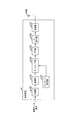
- FIG. 2 is a schematic block diagram illustrating a configuration of the receiving device b1 according to the present embodiment.
- the receiving device b1 includes a receiving antenna b101, a receiving unit b102, a subtracting unit b103, an extended FFT section extracting unit b104, an FFT unit b105, a propagation path estimating unit b106, a restoring unit b107, a demodulating unit b108, a decoding unit b109, A symbol replica generation unit b110, an IFFT unit b111, a GI insertion unit b112, and a filter unit b113 are included.
- the subtraction unit b103, the extended FFT section extraction unit b104, the FFT unit b105, the restoration unit b107, and the filter unit b113 are referred to as a signal extraction unit B1.
- the reception unit b102 receives the transmission signal transmitted by the transmission device a1 via the reception antenna b101.
- the receiving unit b102 performs frequency conversion and analog-digital conversion on the received signal.
- the receiving unit b102 stores the converted received signal.
- the reception unit b102 outputs the received signal to be stored to the subtraction unit b103 and the propagation path estimation unit b106 at the initial processing and the timing when the filter unit b113 described later inputs the reception signal replica to the subtraction unit b103.
- the subtractor b103 subtracts the received signal replica input from the filter unit b113 described later from the received signal input from the receiver b102.
- the subtractor b103 outputs a signal obtained by subtracting the received signal replica to the extended FFT section extractor b104.
- the subtracting unit b103 outputs the received signal input from the receiving unit b102 as it is to the extended FFT section extracting unit b104.
- the extended FFT section extraction unit b104 outputs a signal in a signal processing section that reduces the amount of interference to the FFT unit b105 based on the channel impulse response input from the propagation path estimation unit b106 described later. Moreover, the information which shows the extracted signal processing area is output to the propagation path estimation part b106. Details of this processing will be described later together with the operation principle.
- the FFT unit b105 performs time frequency conversion on the time domain signal input from the extended FFT section extraction unit b104, and outputs the converted frequency domain signal to the restoration unit b107.
- the propagation path estimation unit b106 estimates the channel impulse response in the OFDM symbol section based on the reception signal input from the reception unit b102 and the transmission signal replica input from the GI insertion unit b112 described later.
- an RLS (Recursive Last Square) algorithm may be used, or other algorithms such as an LMS (Least Mean Square) algorithm may be used. Good.
- LMS Least Mean Square
- the propagation path estimation unit b106 is input from the pilot signal stored in advance and the reception unit b102. Based on the received signal, a channel impulse response that varies in time in the OFDM symbol period is estimated.
- the propagation path estimation unit b106 outputs the estimated channel impulse response to the filter unit b113 and the extended FFT section extraction unit b104. Moreover, the propagation path estimation part b106 performs the time frequency conversion corresponding to the signal processing area which the information input from the extended FFT area extraction part b104 shows with respect to the estimated channel impulse response, and estimates a frequency response. The propagation path estimation unit b106 outputs the estimated frequency response to the restoration unit b107 and the demodulation unit b108. Moreover, the propagation path estimation part b106 measures a noise power and interference power in the subcarrier (it is called a pilot subcarrier) by which a pilot signal is arrange
- the restoration unit b107 For each subcarrier, the restoration unit b107 multiplies a frequency response input from the propagation path estimation unit b106 by a symbol replica input from a symbol replica generation unit b110, which will be described later, to obtain a desired signal affected by the propagation path The replica signal is generated.
- the restoration unit b107 adds the generated replica signal to the signal input from the FFT unit b105 for each subcarrier. That is, the restoration unit b107 generates a replica signal of the desired signal based on the propagation path estimation value and the symbol replica, adds the replica signal of the desired signal to the frequency domain signal converted by the FFT unit b105, Each subcarrier component of the received signal is extracted.
- the restoration unit b107 outputs a signal obtained by adding the replica signal to the demodulation unit b108.
- the restoration unit b107 outputs the signal input from the FFT unit b105 to the demodulation unit b108 as it is.
- the signal extraction unit B1 removes the received signal replica from the received signal based on the propagation path estimation value and the symbol replica, and restores the desired signal to remove the ISI and ICI (interference). Each subcarrier component is extracted.
- the demodulation unit b108 calculates a filter coefficient using a ZF (Zero Forcing) standard, an MMSE (Minimum Mean Square Error) standard, and the like, using the frequency response, noise power, and interference power input from the propagation path estimation unit b106. To do.
- the demodulator b108 compensates for fluctuations in the amplitude and phase of the signal (referred to as propagation path compensation) using the calculated filter coefficient.
- the demodulator b108 demaps the signal subjected to propagation path compensation based on the mapping information notified in advance from the transmission device a1, and performs demodulation processing on the demapped signal.
- the demodulator b108 outputs a bit log likelihood ratio (LLR) as a result of the demodulation process to the decoder b109.
- LLR bit log likelihood ratio
- the decoding unit b109 performs, for example, maximum likelihood decoding (MLD; Maximum Likelihood Decoding), maximum a posteriori probability (MAP), log-MAP, Max ⁇ on the demodulated symbols input from the demodulation unit b108.
- MLD Maximum Likelihood Decoding
- MAP maximum a posteriori probability
- log-MAP log-MAP
- Max ⁇ Max ⁇ on the demodulated symbols input from the demodulation unit b108.
- Decoding processing is performed using log-MAP, SOVA (Soft Output Viterbi Algorithm), or the like.
- the decoding unit b109 outputs the bit log likelihood ratio of the decoding result as information data bits. To do.
- the decoding unit b109 outputs the bit log likelihood ratio of the decoding result to the symbol replica generation unit b110.
- the symbol replica generation unit b110 calculates an expected value of the bit log likelihood ratio input from the decoding unit b109 and modulates the calculated expected value to generate a modulation symbol (referred to as a symbol replica).
- the symbol replica generation unit b110 maps the generated symbol replica based on the mapping information notified in advance from the transmission device a1.
- the symbol replica generation unit b110 outputs the mapped symbol replica to the restoration unit b107 and the IFFT unit b111.
- the IFFT unit b111 performs frequency time conversion on the symbol replica input from the symbol replica generation unit b110, and outputs the converted time domain replica signal to the GI insertion unit b112.
- the GI insertion unit b112 generates a transmission signal replica by adding a guard interval for each signal in the FFT interval to the replica signal input from the IFFT unit b111.
- the GI insertion unit b112 outputs the generated transmission signal replica to the propagation path estimation unit b106 and the filter unit b113.
- the filter unit b113 generates a reception signal replica based on the channel impulse response input from the propagation path estimation unit b106 and the transmission signal replica input from the GI insertion unit b112.
- the filter unit b113 outputs the generated reception signal replica to the subtraction unit b103.
- the reception device b1 repeatedly performs the processing from the subtraction unit b103 to the filter unit b113 on the same signal until the decoding unit b109 no longer detects an error or a predetermined number of times (referred to as repetition processing).
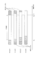
- FIG. 3 is a schematic diagram illustrating an example of a received signal according to the present embodiment. This figure shows the case where the maximum delay does not exceed the GI length and there is no interference due to the previous OFDM symbol.
- the horizontal axis is a time axis, which is discrete time divided by a predetermined time width. Also, in this figure, the hatched area with diagonal lines rising diagonally to the right indicates a guard interval. Also, the hatched area with diagonally upward left lines indicates the received signals of the preceding and following OFDM symbols.
- N is the number of points in the FFT (Fast Fourier Transform) section (also the number of points in the IFFT (Inverse Fast Fourier Transform) section), and N g is the number of GI points.
- the number of points is the number of discrete times.
- the extended FFT section extraction unit b104 inputs the extracted signal to the FFT unit b105.
- the receiving apparatus b1 can extract a signal that does not cause interference due to the preceding and succeeding OFDM symbols.
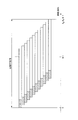
- FIG. 4 is a schematic diagram illustrating an example of an FFT interval selected by the receiving device b1 according to the present embodiment.
- This figure is a case where the maximum delay exceeds the GI length and there is interference due to the previous OFDM symbol.
- the horizontal axis is a time axis, which is discrete time divided by a predetermined time width.
- a hatched area with a diagonal line rising diagonally to the right indicates GI.
- the extended FFT section extraction unit b104 does not fix the number of points to N and selects a section that reduces interference.
- K D denotes a delay time of the maximum delay path (maximum delay time).
- This figure shows a case where the extended FFT section extraction unit b104 selects from the leading edge of the preceding wave path to the end of the maximum delay path. In this figure, there are 12 paths (including preceding wave paths) in this signal processing section.
- the extended FFT interval extraction unit b104 outputs the signal of the signal processing interval to the FFT unit b105 with the selected interval as the signal processing interval. This process will be described later together with the operation principle. Note that a section shorter than a normal FFT section may be selected as the extended FFT section.
- D is is a maximum channel number, here assumed to be equal to the maximum delay time the K D.
- H i, d, k are complex amplitudes at the k-th discrete time in the path of the channel number d of the i-th symbol (referred to as the d-th path), and s i, k are transmission signals in the time domain of the i-th symbol.
- Zi , k are noises in the time domain of the i-th symbol.
- N is the number of points in the FFT interval
- S i, n is the modulation signal of the i-th symbol of the n-th subcarrier
- N g is the number of points in the GI interval (see FIG. 4)
- j is an imaginary unit.
- equation (5) matches the discrete Fourier transform result for the time average of the channel impulse response that is time-varying within the OFDM symbol.
- the propagation path estimation unit b106 estimates W i, n, n using the pilot signal.
- the signal represented by Expression (3) is output from the FFT unit b105 to the demodulation unit b108 as it is via the restoration unit b107.
- the demodulator b108 calculates the demodulated symbol S ′ i, n using the following equation (6).
- Equation (6) ⁇ z 2 is noise power and ⁇ I 2 is ISI and ICI power, which are expressed as in the following Equations (7) and (8).
- E [X] represents an ensemble average of X.
- the propagation path estimation unit b106 calculates these powers using the pilot signal, and calculates the demodulated symbol S ′ i, n using the result in equation (6). Specifically, it is calculated as in the following equation (9).
- Equation (9) is an estimated value of ⁇ z 2 + ⁇ I 2
- P i is a set representing pilot subcarriers in the i-th symbol. Note that this is a calculation method using the fact that Equation (9) can be expressed by the following Equation (10) when it is assumed that a sufficient number of arithmetic averages is equal to the ensemble average.
- the first term represents the power of ISI and ICI
- the second term represents the noise power.
- This equation is for the case where the power of the pilot signal is normalized to 1 and the power average of the frequency response is normalized to 1. That is, this expression is a case where the following expression (11) is satisfied.
- pilot signal power is not 1, an adjustment factor corresponding to that power may be introduced. Further, the normalization of the frequency response is caused by amplitude adjustment when analog-to-digital conversion is performed in the receiving unit b102.
- the demodulator b108 calculates a bit log likelihood ratio from the demodulated symbol S ′ i, n in Equation (6).
- An equivalent amplitude gain is used for this calculation process.
- the bit log likelihood ratio ⁇ is expressed by the following equations (13) and (14) with respect to the equivalent amplitude gain ⁇ i, n of the n-th subcarrier expressed by the following equation (12). It is represented by Here, the equations (13) and (14) are respectively expressed by bit log likelihood ratios ⁇ (b i, n ) of the first bit bits b i, n, 0 and the second bit bits b i, n, 1. , 0 ), ⁇ (b i, n, 1 ).
- the symbol replica generation unit b110 calculates an expected value of the bit log likelihood ratio decoded by the decoding unit b109, and modulates the calculated expected value to generate a symbol replica S ′′ i, n .
- the symbol replica S ′′ i, n is frequency-time converted by the IFFT unit b111, and the GI is inserted by the GI insertion unit b112.
- the transmission signal replica s ′′ i, k output from the GI insertion unit b112 is expressed by the following equation (15).
- the IFFT unit b111 performs inverse fast Fourier transform, and the order of the number of multiplications in this transform is O (Nlog 2 N). is there.
- the propagation path estimation unit b106 estimates the channel impulse response h i, d, k based on the transmission signal replica expressed by the equation (15) and the reception signal input from the reception unit b102. Further, the propagation path estimation unit b106 performs time-frequency conversion after time-averaging the channel impulse responses h i, d, k to calculate the frequency responses W i, n, n .
- the filter unit b113 determines the received signal replica represented by the following equation (16). r ′′ i, k is generated.
- the order of the number of multiplications in the processing performed by the filter unit b113 to generate the received signal replica of Expression (16) is O (DN).
- D ⁇ N in general, it may be considered as O (N).
- the subtractor b103 subtracts the received signal replica r ′′ i, k represented by the equation (16) from the received signal r i, k represented by the equation (1), and the signal r represented by the following equation (17). 'Output i and k .
- the extended FFT interval extraction unit b104 determines a signal selection interval to be output to the FFT unit b105 from the estimated channel impulse response.
- the FFT unit b105 performs a fast Fourier transform.
- the order of the number of multiplications in this conversion is O (Nlog 2 N).
- the restoration unit b107 multiplies the symbol replica S ′′ i, n by the frequency response W i, n, n to obtain a replica signal W i, n, n S ′′ i, of the desired signal affected by the propagation path . n is generated.
- the restoration unit b107 adds the generated replica signal W i, n, n S ′′ i, n to the signal R ′ i, n represented by Expression (18).
- the signal Y i, n after this addition is expressed by the following equation (20).
- This equation (20) means that the desired signal of the nth subcarrier remains and the ICI is removed. By removing ICI, the signal-to-interference noise power ratio (SINR) can be improved, and the transmission characteristics are improved.
- the restoration unit b107 performs the process for generating the signal Y i, n of Expression (20) for each subcarrier, the order of the number of multiplications in this process is O (N).
- the demodulation unit b108 calculates the demodulation symbol S ′ i, n of the n-th subcarrier represented by the following equation (21) from the signal Y i, n represented by the equation (20). Then demodulate.
- the expression (21) is an expression in the case where the removal residual due to the received signal is accurately taken into consideration.
- the present invention is not limited to this, and the removal expression is converted into noise, and the following expression (22) is obtained.
- the demodulated symbol S ′ i, n may be calculated by using it.
- ⁇ I ′ 2 is the power of the ICI removal residual, and can be calculated together with the noise power by the same method as in the initial processing. In this way, even if the equation (22) is used, the characteristic deterioration is small.
- the number of multiplications of order O (N 2 ) is required for calculation of the ICI removal residual term of the second term of the denominator.
- Expression (22) processing can be performed with the number of multiplications of order O (N), and the number of multiplications can be greatly reduced. Therefore, the order of the maximum number of multiplications in each part of the iterative process is O (Nlog 2 N), and the receiving apparatus b1 can perform the iterative process by the process of the number of multiplications of order O (Nlog 2 N).
- V i, n, m, 1 and V i, n, m, 2 are ISI coefficients, the former representing the coefficient from the previous symbol and the latter representing the coefficient from the next symbol.
- the signal is output to the FFT unit b105.
- the receiving apparatus b1 can restore a signal by one conventional FFT process even when synthesizing an interval longer than a normal FFT interval.
- the restoration unit b107 multiplies the symbol replica S ′′ i, n by the frequency response W i, n, n to obtain a replica signal W i, n, n S ′′ i, of the desired signal affected by the propagation path . n is generated.
- the restoration unit b107 adds the generated replica signal W i, n, n S ′′ i, n to the signal R ′ i, n represented by the equation (23).
- the signal Y i, n after this addition is expressed by the following equation (25).
- This equation (25) means that the desired signal of the n-th subcarrier remains and the ISI and ICI are removed.
- SINR can be improved and transmission characteristics are improved by removing ISI and ICI. That is, good reception characteristics can be obtained.
- the demodulation unit b108 demodulates the demodulated symbol S of the n-th subcarrier represented by the following equation (27) from the signal Y i, n represented by the equation (25). 'Calculate i and n and demodulate.
- ⁇ I ′ 2 is the power of the ISI and ICI removal residual, and can be calculated together with the noise power by the same method as in the initial processing.
- the decoding unit b109 performs a decoding process on the bit log likelihood ratios ⁇ (b i, n, 0 ) and ⁇ (b i, n, 1 ) of the demodulated symbol S ′ i, n expressed by Expression (27). I do. Thereafter, the iterative process is repeated. By repeating the above-described iterative process, the transmission characteristics can be greatly improved.
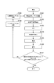
- FIG. 5 is a flowchart showing the operation of the receiving apparatus according to this embodiment. The operation shown in this figure is processing after the reception unit b102 in FIG. 2 outputs the reception signal to the subtraction unit b103 for the first time.
- Step S101 The subtraction unit b103 subtracts the reception signal replica generated in step S109 described later from the reception signal. Then, it progresses to step S102.
- Step S102 The extended FFT section extraction unit b104 extracts an FFT section in which interference is reduced from the signal resulting from the subtraction in Step S101. Thereafter, the process proceeds to step S103.
- Step S103 The FFT unit b105 performs time frequency conversion on the signal in the FFT interval extracted in Step S102. Thereafter, the process proceeds to step S104.
- Step S104 For each subcarrier, the restoration unit b107 outputs the FFT section signal extracted by the extended FFT section extraction unit b104 to the symbol replica generated in step S108 described later with respect to the signal of the conversion result in step S103. The symbol replica signal multiplied by the frequency response is added. Thereafter, the process proceeds to step S105.
- the demodulation unit b108 performs propagation path compensation on the signal resulting from the addition in step S104, and calculates a bit log likelihood ratio. Thereafter, the process proceeds to step S106.
- Step S106 The decoding unit b109 performs a decoding process such as error correction on the bit log likelihood ratio of the calculation result in step S105. Thereafter, the process proceeds to step S107.
- Step S107 The decoding unit b109 determines whether no error is detected in the decoding result in step S106, or whether a predetermined number of processes have been performed. If any of these is true (Yes), the receiving apparatus b1 ends the operation. On the other hand, when it does not correspond to both of these (No), it progresses to step S108. Note that the determination of whether or not there is an error in the decoding result may be performed, for example, in a MAC (Media Access Control) layer.
- the symbol replica generation unit b110 generates a symbol replica from the bit log likelihood ratio of the decoding result in step S106. Thereafter, the process proceeds to step S109.
- the IFFT unit b111, the GI insertion unit b112, and the filter unit b113 generate a received signal replica based on the symbol replica generated in step S108. Then, it progresses to step S101.
- the propagation path estimation part b106 estimates a propagation path estimated value.
- the symbol replica generation unit b110 generates a symbol replica that is a modulation symbol of the demodulated information.
- the signal extraction unit B1 extracts each subcarrier component of the received signal from which interference has been removed in a time interval of an arbitrary length.
- the demodulator b108 demodulates the signal of each subcarrier component of the received signal based on the signal in the time interval extracted by the signal extractor B1. As a result, the receiving device b1 can obtain good reception characteristics while suppressing an increase in calculation amount and circuit scale.
- the receiving apparatus b1 extracts each subcarrier component of the received signal from which ISI and ICI are removed, and demodulates the extracted signal of each subcarrier component. Thereby, the receiving device b1 can prevent an increase in the calculation amount. Further, not only when the delay time of the delayed wave exceeds the guard interval, it is possible to suppress ICI that occurs when the receiving apparatus moves at high speed.
- the filter unit b113 generates a reception signal replica
- the subtraction unit b103 subtracts the reception signal replica
- the restoration unit b107 adds the replica signal of the desired signal.
- demodulation processing is performed has been described.
- the filter unit b113 generates a signal replica obtained by removing the received signal of the desired signal from the received signal
- the subtracting unit b103 generates the replica signal.
- Subtraction may be performed and demodulation processing may be performed for each subcarrier.
- the above equation (17) is replaced by the following equations (28) and (29).
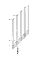
- the section extracted by the extended FFT section extraction unit b104 is from the leading end of the preceding wave to the end of the maximum delay path, but is not limited thereto. For example, it may be possible to extract from the front end to the end of the path with the highest power. Further, the position shown in FIG. 6 may be set as the start position or end position of the section.
- FIG. 6 is a schematic diagram illustrating an example of an FFT interval selected by a receiving apparatus according to a modification of the present embodiment. In this figure, the horizontal axis is the time axis, and the vertical axis is the path.
- the extended FFT section extraction unit b104 may use the tip obtained by removing the guard interval from the preceding wave as the start position of the extended FFT section (time indicated by reference numeral 1). Further, the extended FFT section extraction unit b104 searches, for example, from the preceding wave and starts the end of the path with the highest power (fourth path in FIG. 6) at the start position of the extended FFT section (time denoted by reference numeral 2). It may be. In addition, the extended FFT section extraction unit b104 may search, for example, from the preceding wave, and use the leading end obtained by removing the guard interval from the path with the highest power as the start position of the extended FFT section (time indicated by reference numeral 3). .
- the extended FFT section extraction unit b104 may set, for example, the rearmost position where leakage from the next OFDM symbol does not occur as the end position of the extended FFT section (time indicated by reference numeral 4). In addition, the extended FFT section extraction unit b104 searches for the last position where no leakage from the next OFDM symbol occurs with respect to the path after the path having the highest power by searching from the preceding wave, for example. May be the end position (time indicated by reference numeral 5). Note that the extended FFT section extraction unit b104 may select a predetermined path leading edge or rearmost position instead of the leading edge or rearmost position of the path with the highest power.
- the section extracted by the extended FFT section extraction unit b104 is not limited to the above range, and may be adapted to any length in the sense that the length of the FFT section is different from normal. Good. Also, it does not have to be a guard interval or signal break.
- the communication system performs communication of multicarrier signals.
- the present invention is not limited to this, and is also applicable to communication of single carrier signals using FFT. can do.
- the extended FFT section extraction unit b104 selects a corresponding extended FFT section as a signal processing section. Moreover, the case where the signal of the signal processing area selected by the receiving apparatus b1 is demodulated for each subcarrier and the information bits are decoded has been described. In this embodiment, a case will be described in which the reception device multiplies a window function before extracting a signal in an extended FFT section, and demodulates and decodes the signal using a plurality of subcarriers.
- the transmission device according to the present embodiment is the same transmission device a1 as in the first embodiment, and thus description thereof is omitted.
- the receiving device is referred to as a receiving device b2.
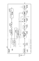
- FIG. 7 is a schematic block diagram showing the configuration of the receiving device b2 according to the second embodiment of the present invention.
- the receiving apparatus b2 (FIG. 7) according to the present embodiment is compared with the receiving apparatus b1 (FIG. 2) according to the first embodiment, the extended FFT section extracting unit b204, the FFT unit b205, and the propagation path of the signal extracting unit B2
- the estimation unit b206 and the restoration unit b207 are different, a window multiplication unit b209 is added, and the demodulation unit b208 is different.
- reception antenna b101, reception unit b102, subtraction unit b103, decoding unit b109, symbol replica generation unit b110, IFFT unit b111, GI insertion unit b112, and filter unit b113 are the first This is the same as the embodiment. A description of the same functions as those in the first embodiment is omitted.
- the extended FFT interval extraction unit b204 extracts the signal of the extended FFT interval based on the channel impulse response estimation value input from the propagation path estimation unit b206, which will be described later, as in the first embodiment, and sends it to the window multiplication unit b209. Output. Further, the extended FFT section extraction unit b204 outputs information indicating the extracted signal processing section to the propagation path estimation unit b206.
- the window multiplication unit b209 multiplies the output result of the extended FFT section extraction unit by a window function and outputs the result to the FFT unit b205. By multiplying the window function in this way, the receiving apparatus b2 can reduce the influence of the ISI and ICI removal residuals.
- a window function of a Hanning window is used as the window function. This process will be described together with the operation principle. Further, the window multiplier b209 outputs the multiplied window information to the propagation path estimator b206.
- the FFT unit b205 performs time frequency conversion on the time domain signal input from the window multiplication unit b209, and outputs the converted frequency domain signal to the restoration unit b207. At this time, not only the same subcarrier but also the signals of neighboring subcarriers are output for one desired subcarrier.
- the FFT unit b205 is different from the FFT unit b105 (see FIG. 2) of the first embodiment in this respect.
- the propagation path estimation unit b206 estimates the channel impulse response as in the first embodiment, and outputs the channel impulse response to the filter unit b113 and the extended FFT section extraction unit b204.
- the propagation path estimation unit b206 corresponds to the estimated channel impulse response, the signal processing interval indicated by the information input from the extended FFT interval extraction unit b204, and the window function information indicated by the information input from the window multiplication unit. Time frequency conversion is performed, and the frequency response of the desired subcarrier and the ICI coefficient to the neighboring subcarrier are output.
- the propagation path estimation unit b206 is different from the propagation path estimation unit b106 (see FIG. 2) of the first embodiment in this point. Moreover, the propagation path estimation part b206 measures noise power and interference power in a pilot subcarrier using the pilot signal memorize
- the restoration unit b207 multiplies the symbol replica input from the symbol replica generation unit b110 by the frequency response input from the propagation path estimation unit b206 and the ICI coefficient to a nearby subcarrier for each subcarrier to be processed.
- the replica signal of the desired signal affected by the propagation path is generated for the desired and nearby subcarriers.
- the restoration unit b207 adds the generated replica signal to the desired and nearby subcarrier signals input from the FFT unit b205. That is, the restoration unit b207 generates a replica signal of the desired signal based on the propagation path estimation value and the symbol replica, and adds the replica signal of the desired signal to the frequency domain signal converted by the FFT unit b205, Each subcarrier component of the received signal is extracted.
- the restoration unit b207 outputs a signal obtained by adding the replica signal to the demodulation unit b208.
- the demodulation unit b208 calculates filter coefficients using the ZF standard, the MMSE standard, and the like using the frequency response, the ICI coefficient, the noise power, and the interference power input from the propagation path estimation unit b206.
- the demodulator b208 performs propagation path compensation using the calculated filter coefficient.
- the demodulator b208 demaps the signal subjected to propagation path compensation based on the mapping information notified in advance from the transmission device a1, and performs demodulation processing on the demapped signal.
- the demodulation unit b208 outputs the bit log likelihood ratio as a result of the demodulation process to the decoding unit b109.
- p (k) represents a window function.
- a window function such as a Hanning window in the receiving apparatus b2
- the influence can be reduced as the ISI and ICI from a far subcarrier.
- the restoration unit b207 multiplies the symbol replica S ′′ i, n + 1 by the frequency response (ICI coefficient) W i, n + 1 , n to generate an n + 1 replica signal W i, n + 1, n S ′′ i, n .
- Restoring unit b207 is' generated on the n + l, the n + l replica signal W i, n + l, n S ' signal R of formula (30)' i, adds the n.
- the signal X i, n, l after this addition is expressed by the following equation (32).
- the demodulator b208 calculates the demodulated symbol S ′ i, n of the n-th subcarrier using the following equation (33).
- the following expression (33) is an expression when the removal residual is approximated with noise.
- L ⁇ 1.
- the reception apparatus b2 uses information on the large and small L subcarriers for the frequency from the nth subcarrier for processing.
- processing may be performed using a different number of subcarriers in the frequency magnitude direction, or processing may be performed using only either the frequency major direction or the minor direction. You may go.
- FIG. 8 is a flowchart showing the operation of the receiving device b2 according to this embodiment.
- the operation shown in this figure is processing after the reception unit b102 in FIG. 7 outputs the reception signal to the subtraction unit b103 for the first time.
- FIG. 8 When the operation of the receiving device b2 according to the present embodiment (FIG. 8) and the operation of the receiving device b1 according to the first embodiment (FIG. 5) are compared, the processes in steps S202 to S205 are different. However, other processes (the processes in steps S101 to S102 and S106 to S109) are the same as those in the first embodiment. A description of the same processing as in the first embodiment is omitted.
- Step S202 The window multiplication unit b209 multiplies the FFT function signal extracted in step S102 by a window function. Then, it progresses to step S203.
- the FFT unit b205 performs time-frequency conversion on the signal resulting from the window multiplication in Step S202. For a processing unit of a certain subcarrier, the subcarrier and a neighboring subcarrier are also used. Thereafter, the process proceeds to step S204.
- Step S204 The reconstruction unit b207 adds, for each subcarrier, the n + 1 replica signal obtained by multiplying the symbol replica generated in step S107 by the ICI coefficient to the (n + 1) th subcarrier signal of the conversion result in step S203. To do.
- Step S205 The demodulation unit b208 performs propagation path compensation on the signal resulting from the addition in Step S204, and calculates a bit log likelihood ratio. Thereafter, the process proceeds to step S106.
- the receiving apparatus b2 can reduce the influence of ICI as the subcarrier is farther from the desired subcarrier by multiplying by the window function. Further, a subcarrier component that is a subcarrier component of the replica signal of the desired signal and is close to the subcarrier is added to the subcarrier component signal. As a result, the receiving apparatus b2 can further improve SINR and obtain high transmission characteristics. Note that the window function need not be multiplied by the short window, that is, nothing. In this case, the ICI reduction effect of the distant subcarriers is lost, but the power of the same subcarrier as the desired subcarrier is not reduced. The SINR improvement effect by using adjacent subcarriers can be obtained even in this case.
- the third embodiment of the present invention will be described in detail with reference to the drawings.
- a case will be described in which the communication system performs communication using a MIMO (Multiple Input Multiple Output) transmission method.
- a case will be described in which a receiving device b3 having R antennas receives a signal transmitted by a transmitting device a3 having T antennas.
- the receiving apparatus b3 receives T streams transmitted from the transmitting apparatus a3 through the T antennas through the R antennas, and performs MIMO separation.
- FIG. 9 is a schematic block diagram showing a configuration of a transmission device a3 according to the third embodiment of the present invention.
- the pilot generation unit a301-t generates a pilot signal in which the receiving device b3 stores in advance the amplitude value of the waveform (or the signal sequence), and outputs the pilot signal to the mapping unit a304-t.
- the encoding unit a302-t encodes information bits to be transmitted to the receiving apparatus b3 using an error correction code such as a convolutional code, a turbo code, and an LDPC code, and generates encoded bits.
- the encoding unit a302-t outputs the generated encoded bits to the modulating unit a303-t.
- the modulation unit a303-t modulates the coded bits input from the coding unit a302-t using a modulation scheme such as PSK or QAM, and generates a modulation symbol.
- the modulation unit a303-t outputs the generated modulation symbol to the mapping unit a304-t.
- the mapping unit a304-t maps the pilot signal input from the pilot generation unit a301-t and the modulation symbol input from the modulation unit a303-t to resources based on predetermined mapping information. And the generated frequency domain signal is output to the IFFT unit a305-t. Also, the mapping information is determined by the transmission device a3 and is notified in advance from the transmission device a3 to the reception device b3.
- the IFFT unit a305-t performs frequency-time conversion on the frequency domain signal input from the mapping unit a304-t to generate a time domain signal.
- the IFFT unit a305-t outputs the generated time domain signal to the GI insertion unit a306-t.
- the GI insertion unit a306-t adds a guard interval for each signal in the FFT interval to the time domain signal input from the IFFT unit a305-t.
- the guard interval is a known signal or the like using a cyclic prefix, a zero padding followed by a zero interval, a Golay code, or the like, which is a part of the rear of the signal in the FFT interval, and the GI insertion unit a306. -T adds such a signal in front of the signal in this FFT interval.
- the GI insertion unit a306-t outputs a signal with the guard interval added to the transmission unit a307-t.
- a guard interval may be inserted behind the FFT interval.
- the transmission unit a307-t performs digital / analog conversion on the signal input from the GI insertion unit a306-t, and shapes the converted analog signal.
- the transmission unit a307-t upconverts the waveform-shaped signal from the baseband to the radio frequency band, and transmits the signal from the transmission antenna a308-t to the reception device b3.
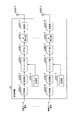
- FIG. 10 is a schematic block diagram showing the configuration of the receiving device b3 according to this embodiment.
- subtracting sections b303-1 to b303-R, extended FFT section extracting sections b304-1 to b304-R, FFT sections b305-1 to b305-R, restoring sections b307-1 to b307-R, received signal replica generating sections B3-1 to B3-R (filter units b313-1 to b313-R described later) are referred to as signal extraction unit B3.
- the reception unit b302-r receives the transmission signal transmitted from the transmission device a3 via the reception antenna b301-r.
- the receiving unit b302-r performs frequency conversion and analog-digital conversion on the received signal.
- the receiving unit b302-r stores the converted received signal.
- the reception unit b302-r generates a reception signal to be stored and generates a subtraction unit b303-r and a reception signal replica at the timing of initial processing and when a summation unit b314-r described later inputs the reception signal replica to the subtraction unit b303-r. Output to part B3-r.
- the subtraction unit b303-r subtracts the reception signal replica input from the reception signal replica generation unit B3-r described later from the reception signal input from the reception unit b302-r.
- the subtractor b303-r outputs a signal obtained by subtracting the received signal replica to the extended FFT section extractor b304-r.
- the subtraction unit b303-r receives the reception signal input from the reception unit b302-r. Is directly output to the extended FFT section extraction unit b304-r.
- the extended FFT section extraction unit b304-r outputs a signal in a signal processing section that reduces the amount of interference to the FFT unit b305-r based on the channel impulse response input from the propagation path estimation unit b306 described later. Further, the information indicating the extracted signal processing section is output to the propagation path estimation unit b306. Details of this processing will be described later together with the operation principle.
- the FFT unit b305-r performs time-frequency conversion on the time-domain signal input from the extended FFT interval extraction unit b304-r, and outputs the converted frequency-domain signal to the restoration unit b307-r.
- the reception signal replica generation unit B3-r estimates the frequency response from each of the antennas a308-t (referred to as the t-th antenna) of the transmission device a3 to the antenna b301-r (referred to as the r-th antenna), It outputs to the demodulation part b308.
- the reception signal replica generation unit B3-r calculates noise power, ISI, and ICI power, and outputs them to the demodulation unit b309.
- the reception signal replica generation unit B3-r generates a reception signal replica of the reception signal received by the r-th antenna from the symbol replica input from the symbol replica generation unit b310-t and outputs the reception signal replica to the subtraction unit b303-r. To do. Details of the configuration and processing of the reception signal replica generation unit B3-r will be described later.
- the restoration unit b307-r For each subcarrier, the restoration unit b307-r multiplies the frequency response input from the propagation path estimation unit b306 by a symbol replica input from a symbol replica generation unit b310-t, which will be described later, to thereby influence the propagation path. A replica signal of the received desired signal is generated.
- the restoration unit b307-r adds the generated replica signal to the signal input from the FFT unit b305-r for each subcarrier. That is, the restoration unit b307-r generates a replica signal of the desired signal based on the propagation path estimation value and the symbol replica, and the replica signal of the desired signal with respect to the frequency domain signal converted by the FFT unit b305-r. Are added to extract each subcarrier component of the received signal.
- the restoration unit b307-r outputs a signal obtained by adding the replica signal to the demodulation unit b308.
- the restoration unit b307-r receives the signal input from the FFT unit b305-r.
- the data is output to the demodulator b308 as it is.
- the demodulation unit b308 calculates filter coefficients using the ZF standard, the MMSE standard, and the like using the frequency response, noise power, and interference power input from the propagation path estimation unit b306.
- the demodulator b308 performs propagation path compensation using the calculated filter coefficient.
- the demodulator b308 demaps the signal subjected to propagation path compensation based on the mapping information notified in advance from the transmission device a1, and performs demodulation processing on the demapped signal.
- the demodulation unit b308 outputs a bit log likelihood ratio as a result of the demodulation process to the decoding unit b309-t for the signal of the transmission signal sequence (referred to as the tth stream) transmitted from the tth antenna.
- the decoding unit b309-t uses the maximum likelihood decoding method, maximum a posteriori probability estimation, log-MAP, Max-log-MAP, SOVA, or the like for the demodulated symbol input from the demodulation unit b308, for example. I do.
- the decoding unit b309-t determines the bit log likelihood ratio of the decoding result as the information data bit. Output as.
- the decoding unit b309-t sends the bit log likelihood ratio of the decoding result to the symbol replica generation unit b310-t. Output.
- the symbol replica generation unit b310-t calculates an expected value of the bit log likelihood ratio input from the decoding unit b309-t and modulates the calculated expected value to generate a symbol replica.
- the symbol replica generation unit b310-t maps the generated symbol replica based on mapping information notified in advance from the transmission device a3.
- the symbol replica generation unit b310-t outputs the mapped symbol replicas to the restoration units b307-1 to b307-R and the reception signal replica generation units B3-1 to B3-R.
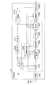
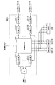
- FIG. 11 is a schematic block diagram showing a configuration of the reception signal replica generation unit B3-r according to the present embodiment.
- the received signal replica generation unit B3-r includes an IFFT unit b311-t, a GI insertion unit b312-t, a propagation path estimation unit b306, a filter unit b313-t, and a summation unit b314. .
- the IFFT unit b311-t performs frequency time conversion on the symbol replica input from the symbol replica generation unit b310-t, and outputs the converted time domain replica signal to the GI insertion unit b312-t.
- the GI insertion unit b312-t adds a guard interval for each signal in the FFT interval to the replica signal input from the IFFT unit b311-t to generate a transmission signal replica.
- the GI insertion unit b312-t outputs the generated transmission signal replica to the propagation path estimation unit b306 and the filter unit b313-t.
- the propagation path estimating unit b306 Based on the received signal input from the receiving unit b302-r and the transmission signal replica signal input from the GI inserting unit b312-t, the propagation path estimating unit b306 receives the signal from each of the t-th antennas in the OFDM symbol period. Estimate the channel impulse response of the propagation path to the r antenna. In the case of the first processing, there is no input from the GI insertion unit b312-t to the propagation path estimation unit b306 (zero), and the propagation path estimation unit b306 receives the pilot signal stored in advance and the reception unit b302-r. Based on the received signal input from, a channel impulse response that varies with time in the OFDM symbol period is estimated.
- the propagation path estimation unit b306 outputs the estimated channel impulse response to the filter unit b313-t and the extended FFT section extraction unit b304-t. Further, the propagation path estimation unit b306 performs time-frequency conversion corresponding to the signal processing interval indicated by the information input from the extended FFT interval extraction unit b304-r on the estimated channel impulse response, and estimates the frequency response. . The propagation path estimation unit b306 outputs the estimated frequency response to the restoration unit b307-r and the demodulation unit b308. Moreover, the propagation path estimation part b306 measures noise power and interference power in a pilot subcarrier using the pilot signal memorize
- the filter unit b313-t Based on the channel impulse response input from the propagation path estimation unit b306 and the transmission signal replica input from the GI insertion unit b312-t, the filter unit b313-t transmits the t-th stream received by the r-th antenna. A received signal replica is generated. The filter unit b313-t outputs the generated received signal replica to the total unit b314. The summation unit b314 sums the reception signal replicas input from the filter unit b313-t, and generates a reception signal replica of the reception signal received by the r-th antenna. The summation unit b314 outputs the generated received signal replica to the subtraction unit b303-r.
- the received signals r i, k, r of the i-th symbol at the k-th discrete time received by the receiving unit b302-r are expressed by the following equations (34), (35).
- T is the number of antennas of the transmission device a3
- D is the maximum propagation path number
- hi , d, k, r, and t are the i-th symbol in the d-th path from the t-th antenna to the r-th antenna.
- k is the complex amplitude at discrete time.
- s i, k, t is the time domain transmission signal of the i th symbol of the t th stream
- z i, k, r is the noise of the i th symbol in the r th antenna.
- N is the number of points in the FFT interval
- S i, n, t is the modulation signal of the n-th subcarrier of the i-th symbol of the t-th stream
- N g is the number of points in the GI interval
- j is an imaginary unit.
- the subtracting unit b303-r subtracts the received signal replica from the received signal r i, k, r expressed by Expression (34).
- the extended FFT interval extraction unit b304-r extracts the FFT interval of the preceding wave, and the FFT unit b305-r outputs the output of the extended FFT interval extraction unit b304-r To time-frequency conversion.
- Signals R ′ i, n, r output from the FFT unit b305-r are expressed by the following equations (36) and (37).
- S ′′ i, m, t is a symbol replica of the signal of the m-th subcarrier of the t-th stream.
- the restoration unit b307-r multiplies the symbol replica S ′′ i, n, t by the frequency response W i, n, n, r, t input from the propagation path estimation unit b306, and is affected by the propagation path. Then, a replica signal W i, n, n, r, t S ′′ i, n, t of a desired signal is generated for the n-th subcarrier of the i-th symbol of the t-th stream received by the r-th antenna.
- the restoration unit b307-r adds the generated replica signals W i, n, n, r, t S ′′ i, n, t to the signal R ′ i, n, r represented by Expression (36). That is, the restoration unit b307-r extracts the subcarrier component of the frequency domain signal transformed by the FFT unit b305-r, and the subcarrier component of the replica signal of the desired signal is extracted from the extracted subcarrier component signal. The desired stream component is added.
- the signal Y i, n, r, t after the addition is expressed by the following equation (38).
- the equation (38) means that the MIMO separation is performed.
- the demodulator b308 calculates the demodulated symbols S ′ i, n, t of the n-th subcarrier of the t-th stream using the following equation (39).
- the following equation (39) is an equation when the removal residual is approximated with noise.
- V i, n, m, r, t, 1 are ISI coefficients from the previous symbol of the t-th stream received by the r-th antenna
- V i, n, m, r, t, 2 is the ISI coefficient after the next one.
- the restoration unit b307-r multiplies the symbol replica S ′′ i, n, t by the frequency response W i, n, n, r, t to obtain a replica signal W i, n, n, r, t S i, n, t are generated.
- the restoration unit b307-r adds the generated replica signals W i, n, n, r, t S ′′ i, n, t to the signal R ′ i, n, r represented by the equation (40).
- the signal Y i, n, r, t after the addition is expressed by the following equation (42).
- the demodulator b308 calculates the demodulated symbols S ′ i, n, t of the n-th subcarrier of the t-th stream using the following equation (43).
- the following equation (43) is an equation when the removal residual is approximated with noise.
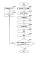
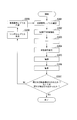
- FIG. 12 is a flowchart showing the operation of the receiving device b3 according to this embodiment. The operation shown in this figure is processing after the reception unit b302-r in FIG. 11 outputs the reception signal to the subtraction unit b303-r for the first time.
- Step S301 The subtraction unit b303-r subtracts the reception signal replica input from step S308 described later from the reception signal. Thereafter, the process proceeds to step S302.
- Step S302 The extended FFT section extraction unit b305-r extracts an FFT section in which interference is reduced from the signal resulting from the subtraction in Step S301. Thereafter, the process proceeds to step S303.
- Step S303 The FFT unit b305-r performs time-frequency conversion on the signal in the FFT interval extracted in Step S302. Thereafter, the process proceeds to step S304.
- Step S304 For each subcarrier, the restoration unit b307 performs the FFT interval extracted by the extended FFT interval extraction unit b304-r on the symbol replica generated in step S308, which will be described later, with respect to the signal resulting from the conversion in step S303. The replica signal multiplied by the frequency response of the signal is added. Thereafter, the process proceeds to step S305.
- Step S305 The demodulator b308-r performs propagation path compensation on the signal resulting from the addition in Step S304, and calculates a bit log likelihood ratio. Thereafter, the process proceeds to step S306.
- Step S306 The decoding unit b309-t performs decoding processing such as error correction on the bit log likelihood ratio of the calculation result in step S305. Thereafter, the process proceeds to step S307.
- Step S307 The decoding unit b309-t determines whether no error is detected in the decoding result in step S306, or whether a predetermined number of processes have been performed. When it corresponds to either of these (Yes), receiving device b3 ends processing. On the other hand, when it does not correspond to both of these (No), it progresses to step S308.
- Step S308 The symbol replica generation unit b310-t generates a symbol replica from the bit log likelihood ratio of the decoding result in step S305. Thereafter, the process proceeds to step S309.
- Step S309 The reception signal replica generation unit B3-r generates a reception signal replica based on the symbol replica generated in step S308. Then, it progresses to step S301.
- the receiving apparatus b3 extracts each subcarrier component of the received signal from which ISI and ICI have been removed, and demodulates the extracted signal of each subcarrier component. Thereby, the receiving apparatus b3 can prevent an increase in the amount of calculation even in the case of the MIMO transmission method.
- the receiving device b3 does not restore the signals of other streams even if it is a desired subcarrier, but may restore it. That is, you may restore
- the demodulator performs MIMO separation, and not only linear processing such as ZF and MMSE, but also maximum likelihood detection (MLD; Maximum Likelihood Detection; hereinafter, the abbreviation MLD means maximum likelihood detection. It is also possible to perform nonlinear processing such as
- the restoration unit b307 adds the generated replica signals W i, n, n, r, t S ′′ i, m, t to the signal R ′ i, n, r represented by the equation (40) for all t. . That is, the restoration unit b307-r extracts the subcarrier component of the frequency domain signal transformed by the FFT unit b305-r, and the subcarrier component of the replica signal of the desired signal is extracted from the extracted subcarrier component signal. All stream components are added.
- the signal Y n, r, t after this addition is expressed by the following equations (56) and (57).
- Expression (56) when expressed as a vector, it is expressed by the following Expressions (58) to (61).
- T represents transposing the matrix.
- M is a modulation multi-level number.
- M 2 in QPSK
- M 4 in 16QAM.
- B i, n, t, q represents the qth bit of the t-th stream constituting the vector S i, n .
- the i-th symbol and the n-th subcarrier are represented, and the subscripts i and n are omitted. That is, ⁇ i, n is expressed as ⁇ , b i, n, t, q as b t, q .
- the bit log likelihood ratio ⁇ (b t, q ) of the bits b t, q in the equation (62) is expressed by the following equation (63).
- Equation (63) the bit log likelihood ratio ⁇ (b t, q ) of Equation (63) is Is expressed by the following equation (64).
- bit log likelihood ratio ⁇ (b t ′, q ′ ) can be calculated using the bit log likelihood ratio ⁇ a (b t ′, q ′ ) output from the decoding unit b309-t ′. Further, since the bit log likelihood ratio ⁇ (b t, q ) obtained in this way is calculated using the bit log likelihood ratio ⁇ a (b t, q ), the corresponding amount is subtracted. It is common. That is, the value output from the demodulation unit b308 to the decoding unit b309-t is ⁇ (b t, q ) ⁇ a (b t, q ). For simplicity, the LLR may be calculated on the assumption that there is no prior information. In this case, the bit log likelihood ratio ⁇ (b t, q ) is expressed by the following equation (67).
- the demodulator b308 calculates the bit log likelihood ratio ⁇ (b t, q ) as a result of the demodulation process using the equation (67), and outputs it to the decoder b309-t.
- the MLD for calculating all candidates has been described.
- the present invention is also applicable to a computational complexity reduction type MLD such as an MLD using QRM-MLD or sphere decoding. it can.
- the section extracted by the extended FFT section extraction unit b304-r is from the leading end of the preceding wave to the end of the maximum delay path, but is not limited thereto. For example, it may be possible to extract from the front end to the end of the path with the highest power. Also in the third embodiment, the window function may be multiplied as in the second embodiment.
- the transmission device a3 (FIG. 9) includes one encoding unit a302-t for one antenna a308-t.
- one encoding unit may be provided for a plurality of antennas.
- the transmission device a3 may include one encoding unit, and distribute and output the result of error correction encoding to the modulation units a303-1 to a303-T according to a predetermined pattern.
- the first to Tth streams may include transmission signals of the same information data signal sequence, or may be transmission signals of different information data signal sequences.
- the transmission device a3 may transmit one information data sequence as the first and second streams and transmit the other information data signal sequence as the third and fourth streams. Good.
- the receiving devices b1, b2, and b3 subtract the received signal replica from the received signal in the time domain.
- the present invention is not limited to this, and the received signal replica may be subtracted from the received signal in the frequency domain.
- the receiving unit b102 outputs the received signal to the extended FFT section extracting unit b104
- the filter unit b113 outputs the received signal replica to the extended FFT section extracting unit b104.
- the extended FFT section extraction unit b104 extracts the signal of the FFT section indicated by the extraction section information from the reception signal input from the reception unit b102 and the reception signal replica input from the filter unit b113, after multiplying by a window.
- the FFT unit b105 performs time frequency conversion on the signal extracted by the extended FFT section extraction unit b104.
- the restoration unit b107 subtracts the received signal replica from the received signal in the FFT interval in which the FFT unit b105 performs the time frequency conversion.
- the restoration unit b107 adds the replica signal by using the subtracted signal as the signal R ′ i, n in Expression (13) or (23).
- transmission devices a1 and a3 and the reception devices b1 to b3 in the above-described embodiment for example, pilot generation units a101 and a301-t, coding units a102 and a302-t, modulation units a103 and a303-t, mapping Unit a104, a304-t, IFFT unit a105, a305-t, GI insertion unit a106, a306-t, transmission unit a107, a307-t, reception unit b102, b302-r, subtraction unit b103, b303-r, extended FFT Section extraction units b104, b204, b304-r, FFT units b105, b205, b305-r, propagation path estimation units b106, b206, b306, restoration units b107, b207, b307-r, demodulation units b108, b208, b308, decoding Parts b109, b309-
- a program for realizing this control function may be recorded on a computer-readable recording medium, and the program recorded on this recording medium may be read into a computer system and executed.
- the “computer system” is a computer system built in the transmission devices a1 and a3 or the reception devices b1 to b3, and includes hardware such as an OS and peripheral devices.
- the “computer-readable recording medium” refers to a storage device such as a flexible medium, a magneto-optical disk, a portable medium such as a ROM or a CD-ROM, and a hard disk incorporated in a computer system.
- the “computer-readable recording medium” is a medium that dynamically holds a program for a short time, such as a communication line when transmitting a program via a network such as the Internet or a communication line such as a telephone line,
- a volatile memory inside a computer system serving as a server or a client may be included and a program that holds a program for a certain time.
- the program may be a program for realizing a part of the functions described above, and may be a program capable of realizing the functions described above in combination with a program already recorded in a computer system.
- the transmission devices a1 and a3 and the reception devices b1 to b3 in the above-described embodiments may be realized as an integrated circuit such as an LSI (Large Scale Integration).
- LSI Large Scale Integration
- Each functional block of the transmission devices a1 and a3 and the reception devices b1 to b3 may be individually made into a processor, or a part or all of them may be integrated into a processor.
- the method of circuit integration is not limited to LSI, and may be realized by a dedicated circuit or a general-purpose processor. Further, in the case where an integrated circuit technology that replaces LSI appears due to progress in semiconductor technology, an integrated circuit based on the technology may be used.
- the present invention is suitable for use in a communication device such as a receiving device.
- a1, a3... transmitting device b1, b2, b3... receiving device, a101, a301-t... pilot generating unit, a102, a302-t .. coding unit, a103, a303-t.
- Modulation unit a104, a304-t ... mapping unit, a105, a305-t ... IFFT unit, a106, a306-t ... GI insertion unit, a107, a307-t ... transmission unit, a108 , A308-t ... transmitting antenna part, b101, b301-r ... receiving antenna, b102, b302-r ... receiving part, b103, b303-r ...
Landscapes
- Engineering & Computer Science (AREA)
- Computer Networks & Wireless Communication (AREA)
- Signal Processing (AREA)
- Power Engineering (AREA)
- Quality & Reliability (AREA)
- Physics & Mathematics (AREA)
- Electromagnetism (AREA)
- Noise Elimination (AREA)
- Radio Transmission System (AREA)
Priority Applications (3)
| Application Number | Priority Date | Filing Date | Title |
|---|---|---|---|
| EP11753242A EP2547015A1 (en) | 2010-03-08 | 2011-03-02 | Receiving device, receiving method, receiving program, and processor |
| US13/583,187 US8824605B2 (en) | 2010-03-08 | 2011-03-02 | Receiving device, receiving method, receiving program, and processor |
| CN2011800127238A CN102870354A (zh) | 2010-03-08 | 2011-03-02 | 接收装置、接收方法、接收程序及处理器 |
Applications Claiming Priority (2)
| Application Number | Priority Date | Filing Date | Title |
|---|---|---|---|
| JP2010-050849 | 2010-03-08 | ||
| JP2010050849A JP2011188206A (ja) | 2010-03-08 | 2010-03-08 | 受信装置、受信方法、受信プログラム、及びプロセッサ |
Publications (1)
| Publication Number | Publication Date |
|---|---|
| WO2011111583A1 true WO2011111583A1 (ja) | 2011-09-15 |
Family
ID=44563387
Family Applications (1)
| Application Number | Title | Priority Date | Filing Date |
|---|---|---|---|
| PCT/JP2011/054754 Ceased WO2011111583A1 (ja) | 2010-03-08 | 2011-03-02 | 受信装置、受信方法、受信プログラム、及びプロセッサ |
Country Status (5)
| Country | Link |
|---|---|
| US (1) | US8824605B2 (enExample) |
| EP (1) | EP2547015A1 (enExample) |
| JP (1) | JP2011188206A (enExample) |
| CN (1) | CN102870354A (enExample) |
| WO (1) | WO2011111583A1 (enExample) |
Cited By (2)
| Publication number | Priority date | Publication date | Assignee | Title |
|---|---|---|---|---|
| CN104301282A (zh) * | 2014-10-29 | 2015-01-21 | 上海大学 | 一种超高速移动ofdm系统的ici自适应抑制方法 |
| EP2834920A4 (en) * | 2012-04-04 | 2015-10-28 | Ericsson Telefon Ab L M | SOFT BIT GENERATION AND CHANNEL ESTIMATION FOR INTERFERENCE CANCELLATION USING A DECODER OUTPUT |
Families Citing this family (8)
| Publication number | Priority date | Publication date | Assignee | Title |
|---|---|---|---|---|
| US9014313B2 (en) * | 2012-02-07 | 2015-04-21 | Lsi Corporation | Error signature analysis for data and clock recovery in a communication system |
| US9544171B2 (en) * | 2013-02-12 | 2017-01-10 | Nokia Solutions And Networks Oy | Zero insertion for ISI free OFDM reception |
| JP6166086B2 (ja) * | 2013-03-28 | 2017-07-19 | 富士通株式会社 | 受信機および信号処理方法 |
| US9312968B2 (en) | 2013-06-07 | 2016-04-12 | Samsung Electronics Co., Ltd. | Computing system with power estimation mechanism and method of operation thereof |
| JP6554735B2 (ja) * | 2015-03-23 | 2019-08-07 | パナソニック株式会社 | ターボ等化器および無線受信装置 |
| US10771297B2 (en) * | 2016-03-11 | 2020-09-08 | Orange | Method and device for multi-service transmission with FC-OFDM modulation and corresponding receiver |
| EP3537678B1 (en) * | 2018-03-08 | 2022-05-04 | Institut Mines Telecom - IMT Atlantique - Bretagne - Pays de la Loire | Pseudo-guard intervals insertion in an fbmc transmitter |
| US11611459B1 (en) * | 2021-08-25 | 2023-03-21 | Qualcomm Incorporated | Symbol configuration for single-carrier for frequency domain equalization waveform |
Citations (8)
| Publication number | Priority date | Publication date | Assignee | Title |
|---|---|---|---|---|
| JP2003218826A (ja) * | 2002-01-23 | 2003-07-31 | Rikogaku Shinkokai | 直交周波数分割多重信号の受信方式及び受信機 |
| JP2005079911A (ja) * | 2003-08-29 | 2005-03-24 | Fujitsu Ltd | Ofdm伝送方式における受信装置 |
| JP2007067878A (ja) * | 2005-08-31 | 2007-03-15 | Sharp Corp | 受信機、通信端末装置および復調方法 |
| WO2007139145A1 (ja) * | 2006-05-30 | 2007-12-06 | Sharp Kabushiki Kaisha | 無線受信機、無線通信システムおよび無線受信方法 |
| JP2009224955A (ja) * | 2008-03-14 | 2009-10-01 | Sony Corp | 復調回路、復調方法、プログラム、および受信装置 |
| JP2009267450A (ja) * | 2008-04-21 | 2009-11-12 | Sharp Corp | 受信機及び受信方法 |
| JP2010028762A (ja) * | 2008-07-24 | 2010-02-04 | Sharp Corp | 通信装置、通信システムおよび受信方法 |
| JP2010050849A (ja) | 2008-08-22 | 2010-03-04 | Aisin Seiki Co Ltd | アンテナ用磁心及びその製造方法 |
Family Cites Families (6)
| Publication number | Priority date | Publication date | Assignee | Title |
|---|---|---|---|---|
| JP4369294B2 (ja) * | 2004-05-13 | 2009-11-18 | 株式会社エヌ・ティ・ティ・ドコモ | 雑音電力推定装置、雑音電力推定方法及び信号検出装置 |
| JP4936680B2 (ja) * | 2005-05-20 | 2012-05-23 | 富士通株式会社 | Ofdm受信方法及び受信装置 |
| EP2023518A1 (en) * | 2006-05-22 | 2009-02-11 | Sharp Kabushiki Kaisha | Receiver and receiving method |
| JP5320174B2 (ja) | 2009-06-12 | 2013-10-23 | シャープ株式会社 | 受信装置及び受信方法 |
| JP5428788B2 (ja) | 2009-11-13 | 2014-02-26 | シャープ株式会社 | 受信装置、受信方法、及び受信プログラム |
| JP5371722B2 (ja) | 2009-12-11 | 2013-12-18 | シャープ株式会社 | 受信装置、受信方法、及び受信プログラム |
-
2010
- 2010-03-08 JP JP2010050849A patent/JP2011188206A/ja active Pending
-
2011
- 2011-03-02 WO PCT/JP2011/054754 patent/WO2011111583A1/ja not_active Ceased
- 2011-03-02 US US13/583,187 patent/US8824605B2/en not_active Expired - Fee Related
- 2011-03-02 EP EP11753242A patent/EP2547015A1/en not_active Withdrawn
- 2011-03-02 CN CN2011800127238A patent/CN102870354A/zh active Pending
Patent Citations (8)
| Publication number | Priority date | Publication date | Assignee | Title |
|---|---|---|---|---|
| JP2003218826A (ja) * | 2002-01-23 | 2003-07-31 | Rikogaku Shinkokai | 直交周波数分割多重信号の受信方式及び受信機 |
| JP2005079911A (ja) * | 2003-08-29 | 2005-03-24 | Fujitsu Ltd | Ofdm伝送方式における受信装置 |
| JP2007067878A (ja) * | 2005-08-31 | 2007-03-15 | Sharp Corp | 受信機、通信端末装置および復調方法 |
| WO2007139145A1 (ja) * | 2006-05-30 | 2007-12-06 | Sharp Kabushiki Kaisha | 無線受信機、無線通信システムおよび無線受信方法 |
| JP2009224955A (ja) * | 2008-03-14 | 2009-10-01 | Sony Corp | 復調回路、復調方法、プログラム、および受信装置 |
| JP2009267450A (ja) * | 2008-04-21 | 2009-11-12 | Sharp Corp | 受信機及び受信方法 |
| JP2010028762A (ja) * | 2008-07-24 | 2010-02-04 | Sharp Corp | 通信装置、通信システムおよび受信方法 |
| JP2010050849A (ja) | 2008-08-22 | 2010-03-04 | Aisin Seiki Co Ltd | アンテナ用磁心及びその製造方法 |
Non-Patent Citations (1)
| Title |
|---|
| K. KATO; R. YAMADA; T. YOSHIMOTO; K SHIMEZAWA; M. KUBOTA; N. OKAMOTO: "Multipath Division Turbo Equalization with Block Inter-Carrier Interference Cancellation in Cellular System with Amplify-and-Forward Relaying", PROC. IEEE PIMRC 2009, September 2009 (2009-09-01) |
Cited By (2)
| Publication number | Priority date | Publication date | Assignee | Title |
|---|---|---|---|---|
| EP2834920A4 (en) * | 2012-04-04 | 2015-10-28 | Ericsson Telefon Ab L M | SOFT BIT GENERATION AND CHANNEL ESTIMATION FOR INTERFERENCE CANCELLATION USING A DECODER OUTPUT |
| CN104301282A (zh) * | 2014-10-29 | 2015-01-21 | 上海大学 | 一种超高速移动ofdm系统的ici自适应抑制方法 |
Also Published As
| Publication number | Publication date |
|---|---|
| CN102870354A (zh) | 2013-01-09 |
| JP2011188206A (ja) | 2011-09-22 |
| EP2547015A1 (en) | 2013-01-16 |
| US20130003901A1 (en) | 2013-01-03 |
| US8824605B2 (en) | 2014-09-02 |
Similar Documents
| Publication | Publication Date | Title |
|---|---|---|
| WO2011111583A1 (ja) | 受信装置、受信方法、受信プログラム、及びプロセッサ | |
| JP5344121B2 (ja) | シングルキャリア伝送方式における無線通信方法および装置 | |
| JP5428788B2 (ja) | 受信装置、受信方法、及び受信プログラム | |
| JP4963703B2 (ja) | 受信機、受信方法および集積回路 | |
| WO2012105291A1 (ja) | 受信装置、受信方法、通信システムおよび通信方法 | |
| WO2010143532A1 (ja) | 受信装置及び受信方法 | |
| JP2006262039A (ja) | 伝搬路推定方法及び伝搬路推定装置 | |
| JP5254180B2 (ja) | 受信装置、受信方法、通信システムおよび通信方法 | |
| JP5539832B2 (ja) | 受信装置、受信方法、受信プログラム | |
| KR100816032B1 (ko) | 반복적 다중 사용자 검파를 통한 데이터 송수신 방법 및 그장치 | |
| JP5030311B2 (ja) | 受信機、受信方法および集積回路 | |
| JP5641816B2 (ja) | 受信装置及び受信方法 | |
| JP5371722B2 (ja) | 受信装置、受信方法、及び受信プログラム | |
| JPWO2006006238A1 (ja) | マルチキャリア受信方法及びマルチキャリア受信装置 | |
| WO2011158727A1 (ja) | 無線通信装置、受信方法およびそのプログラム | |
| JP5837797B2 (ja) | 受信装置、受信方法、通信システムおよび通信方法 | |
| WO2018163257A1 (ja) | 通信装置および受信信号処理方法 | |
| Chen et al. | Fractional Cosine Transform (FrCT)-Turbo based OFDM for underwater acoustic communication | |
| JP2013223177A (ja) | 受信装置、受信方法および受信プログラム | |
| WO2012011399A1 (ja) | 受信装置および受信方法 | |
| WO2012169303A1 (ja) | 受信装置、受信方法、制御プログラムおよび集積回路 | |
| JP2010278850A (ja) | 受信装置、受信方法、及び受信プログラム |
Legal Events
| Date | Code | Title | Description |
|---|---|---|---|
| WWE | Wipo information: entry into national phase |
Ref document number: 201180012723.8 Country of ref document: CN |
|
| 121 | Ep: the epo has been informed by wipo that ep was designated in this application |
Ref document number: 11753242 Country of ref document: EP Kind code of ref document: A1 |
|
| WWE | Wipo information: entry into national phase |
Ref document number: 13583187 Country of ref document: US |
|
| NENP | Non-entry into the national phase |
Ref country code: DE |
|
| WWE | Wipo information: entry into national phase |
Ref document number: 2011753242 Country of ref document: EP |