WO2011111148A1 - 内燃機関の燃料噴射装置 - Google Patents
内燃機関の燃料噴射装置 Download PDFInfo
- Publication number
- WO2011111148A1 WO2011111148A1 PCT/JP2010/053768 JP2010053768W WO2011111148A1 WO 2011111148 A1 WO2011111148 A1 WO 2011111148A1 JP 2010053768 W JP2010053768 W JP 2010053768W WO 2011111148 A1 WO2011111148 A1 WO 2011111148A1
- Authority
- WO
- WIPO (PCT)
- Prior art keywords
- fuel
- alcohol
- combustion engine
- internal combustion
- fuel pressure
- Prior art date
- Legal status (The legal status is an assumption and is not a legal conclusion. Google has not performed a legal analysis and makes no representation as to the accuracy of the status listed.)
- Ceased
Links
Images





Classifications
-
- F—MECHANICAL ENGINEERING; LIGHTING; HEATING; WEAPONS; BLASTING
- F02—COMBUSTION ENGINES; HOT-GAS OR COMBUSTION-PRODUCT ENGINE PLANTS
- F02M—SUPPLYING COMBUSTION ENGINES IN GENERAL WITH COMBUSTIBLE MIXTURES OR CONSTITUENTS THEREOF
- F02M25/00—Engine-pertinent apparatus for adding non-fuel substances or small quantities of secondary fuel to combustion-air, main fuel or fuel-air mixture
-
- F—MECHANICAL ENGINEERING; LIGHTING; HEATING; WEAPONS; BLASTING
- F02—COMBUSTION ENGINES; HOT-GAS OR COMBUSTION-PRODUCT ENGINE PLANTS
- F02M—SUPPLYING COMBUSTION ENGINES IN GENERAL WITH COMBUSTIBLE MIXTURES OR CONSTITUENTS THEREOF
- F02M43/00—Fuel-injection apparatus operating simultaneously on two or more fuels, or on a liquid fuel and another liquid, e.g. the other liquid being an anti-knock additive
- F02M43/04—Injectors peculiar thereto
-
- F—MECHANICAL ENGINEERING; LIGHTING; HEATING; WEAPONS; BLASTING
- F02—COMBUSTION ENGINES; HOT-GAS OR COMBUSTION-PRODUCT ENGINE PLANTS
- F02D—CONTROLLING COMBUSTION ENGINES
- F02D19/00—Controlling engines characterised by their use of non-liquid fuels, pluralities of fuels, or non-fuel substances added to the combustible mixtures
- F02D19/06—Controlling engines characterised by their use of non-liquid fuels, pluralities of fuels, or non-fuel substances added to the combustible mixtures peculiar to engines working with pluralities of fuels, e.g. alternatively with light and heavy fuel oil, other than engines indifferent to the fuel consumed
- F02D19/0602—Control of components of the fuel supply system
- F02D19/0607—Control of components of the fuel supply system to adjust the fuel mass or volume flow
- F02D19/061—Control of components of the fuel supply system to adjust the fuel mass or volume flow by controlling fuel injectors
-
- F—MECHANICAL ENGINEERING; LIGHTING; HEATING; WEAPONS; BLASTING
- F02—COMBUSTION ENGINES; HOT-GAS OR COMBUSTION-PRODUCT ENGINE PLANTS
- F02D—CONTROLLING COMBUSTION ENGINES
- F02D19/00—Controlling engines characterised by their use of non-liquid fuels, pluralities of fuels, or non-fuel substances added to the combustible mixtures
- F02D19/06—Controlling engines characterised by their use of non-liquid fuels, pluralities of fuels, or non-fuel substances added to the combustible mixtures peculiar to engines working with pluralities of fuels, e.g. alternatively with light and heavy fuel oil, other than engines indifferent to the fuel consumed
- F02D19/0663—Details on the fuel supply system, e.g. tanks, valves, pipes, pumps, rails, injectors or mixers
- F02D19/0668—Treating or cleaning means; Fuel filters
-
- F—MECHANICAL ENGINEERING; LIGHTING; HEATING; WEAPONS; BLASTING
- F02—COMBUSTION ENGINES; HOT-GAS OR COMBUSTION-PRODUCT ENGINE PLANTS
- F02D—CONTROLLING COMBUSTION ENGINES
- F02D19/00—Controlling engines characterised by their use of non-liquid fuels, pluralities of fuels, or non-fuel substances added to the combustible mixtures
- F02D19/06—Controlling engines characterised by their use of non-liquid fuels, pluralities of fuels, or non-fuel substances added to the combustible mixtures peculiar to engines working with pluralities of fuels, e.g. alternatively with light and heavy fuel oil, other than engines indifferent to the fuel consumed
- F02D19/08—Controlling engines characterised by their use of non-liquid fuels, pluralities of fuels, or non-fuel substances added to the combustible mixtures peculiar to engines working with pluralities of fuels, e.g. alternatively with light and heavy fuel oil, other than engines indifferent to the fuel consumed simultaneously using pluralities of fuels
- F02D19/082—Premixed fuels, i.e. emulsions or blends
- F02D19/084—Blends of gasoline and alcohols, e.g. E85
-
- F—MECHANICAL ENGINEERING; LIGHTING; HEATING; WEAPONS; BLASTING
- F02—COMBUSTION ENGINES; HOT-GAS OR COMBUSTION-PRODUCT ENGINE PLANTS
- F02M—SUPPLYING COMBUSTION ENGINES IN GENERAL WITH COMBUSTIBLE MIXTURES OR CONSTITUENTS THEREOF
- F02M61/00—Fuel-injectors not provided for in groups F02M39/00 - F02M57/00 or F02M67/00
- F02M61/16—Details not provided for in, or of interest apart from, the apparatus of groups F02M61/02 - F02M61/14
-
- Y—GENERAL TAGGING OF NEW TECHNOLOGICAL DEVELOPMENTS; GENERAL TAGGING OF CROSS-SECTIONAL TECHNOLOGIES SPANNING OVER SEVERAL SECTIONS OF THE IPC; TECHNICAL SUBJECTS COVERED BY FORMER USPC CROSS-REFERENCE ART COLLECTIONS [XRACs] AND DIGESTS
- Y02—TECHNOLOGIES OR APPLICATIONS FOR MITIGATION OR ADAPTATION AGAINST CLIMATE CHANGE
- Y02T—CLIMATE CHANGE MITIGATION TECHNOLOGIES RELATED TO TRANSPORTATION
- Y02T10/00—Road transport of goods or passengers
- Y02T10/10—Internal combustion engine [ICE] based vehicles
- Y02T10/30—Use of alternative fuels, e.g. biofuels
Definitions
- the present invention relates to a fuel injection device for an internal combustion engine.
- FIG. 8 is a graph showing the relationship between the distillation ratio and temperature of E80 (80% ethanol mixed fuel), E20 (20% ethanol mixed fuel), and E0 (gasoline 100%). Since gasoline is composed of multiple components and contains low boiling components, it has excellent vaporization characteristics even at low temperatures. On the other hand, since alcohol is a single component, its boiling point is determined and its boiling point is high (about 78 ° C. in the case of ethanol). For this reason, as can be seen from FIG. 8, a mixed fuel having a high alcohol concentration, such as E80, has a drawback that it is very difficult to vaporize at a temperature lower than the boiling point of the alcohol. In the case of a mixed fuel having a relatively low alcohol concentration, such as E20, vaporization may be easier than in the case of 100% gasoline due to an azeotropic phenomenon.
- Japanese Patent Application Laid-Open No. 2008-248840 in an engine supplied with a mixed fuel of gasoline and ethanol, water is added to a fuel tank in which the mixed fuel is stored, and ethanol water is separated and extracted from the mixed fuel.
- An internal combustion engine in which alcohol water is injected into an intake port during a load operation is disclosed.
- This internal combustion engine includes a main tank that communicates with a gasoline injection valve and a subtank that communicates with an ethanol water injection valve. Residual fuel (gasoline) after water addition is used as a main tank, and separated ethanol water is used as a subtank. Each tank is supposed to store. According to this internal combustion engine, gasoline or ethanol water can be injected at a desired timing, so that the above problem can be solved.
- the present invention has been made in order to solve the above-described problems, and in an internal combustion engine using a mixed fuel of gasoline and alcohol, it is possible to suppress an emission deterioration when using the mixed fuel with a simple configuration.
- An object of the present invention is to provide a fuel injection device for an internal combustion engine.
- a first invention is a fuel injection device for an internal combustion engine,
- a fuel injector having a tip portion in which an internal space for storing fuel and an injection port for injecting fuel are formed, and an alcohol component in a mixed fuel of gasoline and alcohol can be selectively adsorbed in the internal space.
- the adsorbent has a characteristic that the amount of adsorbed alcohol decreases when the fuel pressure is low, and the amount of adsorbed alcohol increases when the fuel pressure is high, Determination means for determining the presence or absence of a request to desorb alcohol adsorbed on the adsorbent; Control means for controlling the fuel pressure to a predetermined low fuel pressure when it is determined that the request is present; Desorption amount estimation means for estimating the desorption amount of alcohol desorbed from the adsorbent; Correction means for correcting the deviation of the air-fuel ratio of the internal combustion engine based on the alcohol desorption amount; It is characterized by providing.
- the desorption amount estimation means estimates the alcohol desorption amount based on a fuel pressure and a fuel temperature in the internal space.
- the correction means includes A concentration estimation means for estimating an alcohol concentration of fuel injected from the fuel injector (hereinafter referred to as a second alcohol concentration) based on the alcohol desorption amount; A change in the air-fuel ratio corresponding to an increase in the second alcohol concentration with respect to the first alcohol concentration is corrected by increasing or decreasing the injection amount.
- a fourth invention is any one of the first to third inventions,
- the determination means includes means for acquiring a water temperature of the internal combustion engine, and determines that the request is present when the water temperature is higher than a predetermined value.
- Means for controlling the fuel pressure to a first high fuel pressure during a cold start of the internal combustion engine Means for controlling a fuel pressure to a second high fuel pressure lower than the first high fuel pressure and higher than the low fuel pressure when it is determined that the request is not required immediately after the internal combustion engine is started; Is further provided.
- the second high fuel pressure is a value in the vicinity of the first high fuel pressure.
- an adsorbent capable of selectively adsorbing an alcohol component in a mixed fuel of gasoline and alcohol is installed in the internal space at the tip. For this reason, according to the fuel injector of the present invention, the alcohol concentration of the injected fuel can be immediately reduced when necessary (for example, during cold start). As a result, the above-described effect can be obtained without providing a fuel injector dedicated to alcohol, so that the fuel supply system can be simplified, and cost and weight can be reduced.
- the fuel pressure is controlled to a predetermined low fuel pressure according to the request.
- the internal combustion engine performs air-fuel ratio control based on the alcohol concentration (first alcohol concentration) of the mixed fuel supplied to the fuel injector. For this reason, when the alcohol concentration of the fuel injected from the fuel injector is increased by the desorbed alcohol, the air-fuel ratio of the internal combustion engine deviates from the control target air-fuel ratio. Further, when the alcohol concentration of the mixed fuel changes, the theoretical air-fuel ratio of the mixed fuel also changes.
- the air-fuel ratio deviation of the internal combustion engine is corrected based on the amount of alcohol desorbed from the alcohol adsorbent. For this reason, according to the present invention, even when the alcohol component is desorbed from the adsorbent, it is possible to effectively suppress the deterioration of the emission due to the air-fuel ratio deviation.
- the alcohol desorption amount desorbed from the adsorbent has a correlation with the fuel pressure and fuel temperature in the internal space where the adsorbent is installed. For this reason, according to the present invention, it is possible to accurately estimate the alcohol desorption amount based on these state quantities.
- the change in the air-fuel ratio due to the increase in the second alcohol concentration is corrected by the increase or decrease in the fuel injection amount. Therefore, according to the present invention, the air-fuel ratio of the internal combustion engine can be controlled to the control target air-fuel ratio even when the alcohol component is desorbed from the adsorbent.
- the water temperature of the internal combustion engine is higher than a predetermined value, it is determined that there is a request for desorbing the alcohol adsorbed on the adsorbent.
- the engine temperature rises alcohol-specific vaporization defects do not occur.
- the present invention it is possible to effectively suppress the situation where the detached alcohol is discharged as unburned alcohol.
- the fuel pressure is controlled to the first high fuel pressure when the internal combustion engine is cold started. If there is no desorption request after startup, the fuel pressure is controlled to a second high fuel pressure lower than the first high fuel pressure.
- the fuel pressure is controlled to the first high fuel pressure, the alcohol concentration of the mixed fuel injected from the fuel injector can be effectively reduced.
- the fuel pressure is controlled to the second high fuel pressure, the fuel efficiency can be improved as compared with the case where the fuel pressure is controlled to the first high fuel pressure.
- the fuel pressure is controlled to the first high fuel pressure at the time of cold start where reduction of alcohol concentration should be prioritized, and the fuel pressure is changed during the period when priority is given to fuel consumption after the start of desorption request. Controlled to a high fuel pressure of 2. For this reason, according to the present invention, it is possible to achieve both the suppression of emission deterioration and the improvement of fuel efficiency at a high level.
- the second high fuel pressure is set to a value in the vicinity of the first high fuel pressure. For this reason, according to the present invention, it is possible to effectively avoid a situation in which a large amount of alcohol adsorbed on the adsorbent is desorbed before a desorption request is issued.
- Embodiment 1 of this invention It is a figure for demonstrating the system configuration
- FIG. 1 is a diagram for explaining a system configuration according to the first embodiment of the present invention.
- the system of the present embodiment includes an internal combustion engine 10.
- the internal combustion engine 10 is used as a power source of a vehicle, for example.
- the internal combustion engine 10 of this embodiment shall be an in-line 4 cylinder type, the number of cylinders and cylinder arrangement
- positioning of an internal combustion engine in this invention are not specifically limited.
- FIG. 1 shows a cross section of one cylinder of the internal combustion engine 10.
- the internal combustion engine 10 can be operated with gasoline as fuel, and can also be operated with a fuel obtained by mixing alcohol such as ethanol or methanol and gasoline (hereinafter also referred to as “alcohol mixed fuel” or “mixed fuel”). It is a thing.
- the alcohol-mixed fuel can be used from a low concentration (for example, about several percent) to a high concentration (for example, 80% or more) of the alcohol component (ratio of the alcohol component).
- An intake passage 12 and an exhaust passage 14 are connected to the internal combustion engine 10.
- An air flow meter 16 that detects the amount of intake air is disposed in the intake passage 12.
- a throttle valve 18 is disposed downstream of the air flow meter 16. The opening degree of the throttle valve 18 is adjusted by the operation of the throttle motor 20.
- a throttle position sensor 22 for detecting the opening degree of the throttle valve 18 is disposed in the vicinity of the throttle valve 18.
- a catalyst 15 for purifying exhaust gas is installed in the exhaust passage 14.
- a fuel injector 26 for injecting fuel into the intake port 11 is disposed in each cylinder of the internal combustion engine 10.
- Each cylinder of the internal combustion engine 10 is further provided with an intake valve 28, a spark plug 30 and an exhaust valve 32.
- a crank angle sensor 38 capable of detecting a rotation angle (crank angle) of the crankshaft 36 is installed in the vicinity of the crankshaft 36 of the internal combustion engine 10.
- the crank angle sensor 38 can detect the crank angle and the engine speed of the internal combustion engine 10.
- the system of the present embodiment includes an accelerator position sensor 24 that detects the amount of depression of an accelerator pedal in a driver's seat of a vehicle on which the internal combustion engine 10 is mounted, a water temperature sensor 42 that detects a cooling water temperature of the internal combustion engine 10, and an internal combustion engine.
- a starter 44 having an electric motor that rotationally drives the crankshaft 36 when the engine 10 is started, a fuel pump 46, a fuel property sensor 48, a fuel pressure sensor 60, a fuel temperature sensor 62, and an ECU (Electronic Control Unit) 50 And.
- Various sensors and actuators including those described above are electrically connected to the ECU 50.
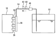
- FIG. 2 is a diagram schematically showing a fuel system for supplying fuel to the internal combustion engine 10.
- the system of this embodiment includes a fuel tank 52.
- the fuel tank 52 is connected to a delivery pipe 56 via a fuel supply passage 54.
- a fuel pump 46 for pressurizing the fuel is installed in the middle of the fuel supply passage 54.
- the installation location of the fuel pump 46 is not limited to this.
- the fuel pump 46 may be installed in the fuel tank 52.
- a fuel pressure sensor 60 for detecting the fuel pressure and a fuel temperature sensor 62 for detecting the temperature of the fuel are installed on the downstream side of the fuel pump 46.
- the fuel stored in the fuel tank 52 is pressurized by the fuel pump 46 and sent to the delivery pipe 56 through the fuel supply passage 54. Then, fuel is distributed to the fuel injectors 26 of the respective cylinders by the delivery pipe 56.
- the fuel pump 46 is configured such that the fuel pressure can be adjusted to a pressure commanded from the ECU 50 and sent to the delivery pipe 56. That is, in the system of the present embodiment, the fuel pressure inside the fuel injector 26 (that is, the fuel injection pressure) can be adjusted by the fuel pump 46.
- the alcohol concentration of the fuel supplied to the fuel injector 26, that is, the fuel stored in the fuel tank 52 depends on the alcohol concentration of the fuel selected by the user for refueling. Increase or decrease.
- the alcohol concentration of the fuel in the tank can be detected by the fuel property sensor 48 provided in the middle of the fuel supply passage 54.
- the fuel property sensor 48 for example, a sensor that detects the alcohol concentration by measuring the dielectric constant, refractive index, etc. of the fuel can be used.
- the installation position of the fuel property sensor 48 is not limited to the illustrated configuration.
- the fuel property sensor 48 may be installed in the fuel tank 52 or the delivery pipe 56.
- the method for detecting the alcohol concentration of the fuel in the tank is not limited to the method using the fuel property sensor 48.
- the alcohol concentration of the fuel may be detected (estimated) from the learned value in the air-fuel ratio feedback control. That is, since the value of the theoretical air-fuel ratio is different between gasoline and alcohol, the value of the theoretical air-fuel ratio of the alcohol mixed fuel differs depending on the alcohol concentration. Therefore, the alcohol concentration of the fuel in the tank is detected (estimated) based on the value of the theoretical air-fuel ratio learned by feeding back a signal from an air-fuel ratio sensor (not shown) provided in the exhaust passage 14. Is possible.
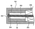
- FIG. 3 is an enlarged cross-sectional view of the tip portion of the fuel injector 26 provided in the internal combustion engine 10 of the present embodiment.
- the fuel injector 26 has a tip 261.
- the tip 261 is formed with an injection port 262 for injecting fuel and an internal space 263 for storing the fuel (filled with fuel).
- a needle valve 264 as an injection valve is inserted into the internal space 263.
- the injection port 262 is opened and closed by this needle valve 264.
- a plunger 265 is integrally provided on the proximal end side of the needle valve 264.
- a solenoid coil 266 is installed around the plunger 265.
- the solenoid coil 266 When the solenoid coil 266 is energized, the plunger 265 is attracted by the solenoid coil 266, and the plunger 265 and the needle valve 264 move to the proximal end side, thereby opening the injection port 262. Thereby, the fuel in the internal space 263 is injected from the injection port 262. When the energization of the solenoid coil 266 is cut off, the plunger 265 and the needle valve 264 are returned to their original positions by the biasing force of a spring (not shown), the injection port 262 is closed, and the injection is stopped.
- the fuel pressure in the internal space 263 of the fuel injector 26 (hereinafter also simply referred to as “fuel pressure”) can be controlled from low pressure to high pressure by a command from the ECU 50 to the fuel pump 46 as described above.
- An adsorbent 58 is installed in the internal space 263 of the tip 261 of the fuel injector 26.
- the adsorbent 58 is disposed in a cylindrical shape along the inner periphery of the internal space 263. That is, the adsorbent 58 is disposed so as to surround the outer peripheral side of the needle valve 264.
- an adsorbent 58 having a property capable of selectively adsorbing an alcohol component in the alcohol mixed fuel is selected.
- a constituent material of such an adsorbent 58 a highly hydrophilic porous body having molecular-level pores capable of taking in alcohol molecules can be used, and typically, zeolite is preferably used.
- zeolites those having a strong polarity are particularly preferable.
- a highly polar zeolite it is possible to reliably select and adsorb strongly polar alcohol molecules from the fuel containing the gasoline component.
- the pore size and the like differ depending on the skeleton structure of the porous material used as the adsorbent 58 (for zeolite, A type, Y type, X type, etc.), it depends on the size of the target alcohol molecule.
- A-type zeolite can be used particularly preferably.
- Embodiment 1 (Alcohol adsorption / desorption in adsorbent)
- the adsorbent 58 has a small amount of alcohol adsorbed on the adsorbent 58 (hereinafter referred to as “alcohol adsorbing amount”) when the surrounding fuel pressure is low, and an alcohol adsorbing amount becomes large when the fuel pressure is high. It has the characteristic.
- the alcohol concentration of the fuel injected from the fuel injector 26 is controlled by controlling the amount of alcohol adsorbed on the adsorbent 58 using this characteristic, so that the fuel supplied to the fuel injector 26 (that is, the fuel concentration) It is possible to make it lower than the alcohol concentration of the fuel in the tank.
- the alcohol component in the mixed fuel in the internal space 263 is selectively adsorbed by the adsorbent 58. For this reason, the alcohol concentration of the mixed fuel in the internal space 263 increases and the gasoline concentration increases. Therefore, by injecting the fuel from the fuel injector 26 with the fuel pressure being increased, the alcohol concentration of the fuel injected from the fuel injector 26 can be made lower than the alcohol concentration of the fuel in the tank.
- FIG. 4 is a diagram showing the relationship between the fuel pressure and the amount of alcohol adsorbed by the adsorbent 58.
- the alcohol adsorption amount decreases when the fuel pressure is low, and the alcohol adsorption amount increases when the fuel pressure is high.
- the alcohol adsorption amount has hysteresis with respect to the history of the fuel pressure. That is, the change in the amount of alcohol adsorbed in the process of adsorbing the alcohol on the adsorbent 58 by increasing the fuel pressure from low pressure to high pressure is represented by the curve on the right side in FIG. 4, and the fuel pressure is decreased from high pressure to low pressure.
- the change in the amount of adsorbed alcohol in the process of desorbing alcohol from the adsorbent 58 is represented by the left curve in FIG.
- the ECU 50 changes the fuel pressure in the internal space 263 of the fuel injector 26 by switching the set pressure value of the fuel pump 46 between a low pressure and a high pressure, thereby controlling the adsorption of alcohol to the adsorbent 58 or the adsorption
- the desorption of alcohol from the material 58 can be controlled.
- the alcohol adsorption amount of the adsorbent 58 is saturated when the fuel pressure rises to P2 in FIG. For this reason, when adsorbing alcohol on the adsorbent 58, the fuel pressure is preferably set to P2 or higher. Thereby, the alcohol adsorption capacity of the adsorbent 58 can be fully extracted.
- alcohol can be adsorbed to the adsorbent 58 at a fuel pressure equal to or higher than P1 in FIG. For this reason, when adsorbing alcohol on the adsorbent 58, the fuel pressure may be increased to at least a value higher than P1.
- FIG. 5 is a diagram showing the relationship between the required fuel injection amount of E85 (85% ethanol mixed fuel) and E0 (100% gasoline) and the temperature.
- E85 85% ethanol mixed fuel
- E0 100% gasoline
- the alcohol component that is many times the amount of the gasoline component that contributed to the combustion cannot be vaporized and passes through the combustion chamber without being burned, and flows into the exhaust passage as HC.
- the amount of HC emission into the atmosphere tends to be extremely large at the cold start.
- the above function is used to control the alcohol concentration of the fuel injected from the fuel injector 26 to be lower than the alcohol concentration of the fuel in the tank. It was decided to. Thereby, even when the alcohol concentration of the fuel in the tank is high, at the time of cold start, a fuel having a lower alcohol concentration and higher gasoline concentration than the fuel in the tank (hereinafter referred to as “alcohol concentration-reducing fuel”). It can be injected from the fuel injector 26. Thereby, good startability with good fuel can be obtained, and the amount of HC emission into the atmosphere can be sufficiently reduced.
- the alcohol concentration-reduced fuel can be generated in the internal space 263 located immediately before the injection port 262. Therefore, the alcohol concentration-reduced fuel can be injected from the initial injection at the start. it can.
- the alcohol concentration-reducing fuel is generated at a position on the front side of the fuel injector 26 (for example, the delivery pipe 56), at least until the fuel in the fuel injector 26 is replaced with the alcohol concentration-reducing fuel. The alcohol concentration-reducing fuel cannot be injected unless the fuel injection is repeated.
- the ability to inject alcohol concentration-reducing fuel from the initial injection at start-up is extremely effective for reducing HC emissions into the atmosphere for the following reasons.
- the catalyst 15 is not warmed by the exhaust gas and is not activated.
- the HC discharged from the internal combustion engine 10 is not purified by the catalyst 15 but is directly discharged into the atmosphere.
- exhaust gas begins to flow into the catalyst 15, the temperature of the catalyst 15 rises, and catalytic activity begins to be expressed, so HC begins to be purified by the catalyst 15.
- the amount of HC discharged from the internal combustion engine 10 is reduced within the first few cycles when the temperature of the catalyst 15 has not risen. It is extremely important to do this.
- the alcohol concentration-reducing fuel can be injected from the initial injection at the time of start-up, so that the amount of the alcohol component flowing into the exhaust passage 14 without being burned can be surely reduced. . For this reason, the amount of HC discharged into the atmosphere at the time of cold start can be reduced extremely effectively.
- the adsorbent 58 cannot adsorb alcohol any more. Therefore, after the internal combustion engine 10 is started, fuel injection from the fuel injector 26 is repeated, whereby the alcohol concentration of the injected fuel returns to the original concentration, that is, the alcohol concentration of the fuel in the tank. However, until then, the temperature of the catalyst 15 rises and the activity is expressed, and HC begins to be purified by the catalyst 15. Therefore, the discharge of HC into the atmosphere is sufficiently suppressed. Further, since the temperature of the internal combustion engine 10 rises until the alcohol concentration of the fuel injected from the fuel injector 26 returns to the original concentration, vaporization of the alcohol component is promoted. For this reason, the deterioration of the operational stability of the internal combustion engine 10 after starting can be sufficiently suppressed.
- the apparatus determines the fuel injection amount on the assumption that the fuel in the tank is directly injected from the fuel injector 26.
- the alcohol concentration of the mixed fuel containing desorbed alcohol (hereinafter referred to as “desorbed alcohol-containing fuel”) is higher than that of the fuel in the tank. For this reason, during the period in which the desorbed alcohol-containing fuel is injected from the fuel injector 26, a deviation occurs in the air-fuel ratio of the internal combustion engine 10.
- the air-fuel ratio correction control is executed. More specifically, the concentration of the desorbed alcohol-containing fuel injected from the fuel injector 26 is estimated, and the injection amount is increased or decreased according to the concentration so that the air-fuel ratio of the internal combustion engine 10 becomes the control target air-fuel ratio. It will be corrected. Thereby, deterioration of HC emission due to discharge of unburned alcohol can be effectively suppressed.
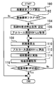
- FIG. 6 is a flowchart of a routine executed by the ECU 50 in the present embodiment in order to realize the air-fuel ratio correction described above.
- the routine shown in FIG. 6 is repeatedly executed during a period in which the alcohol concentration reduction control is executed at the cold start, that is, a period in which the fuel pressure is set to a high fuel pressure.
- a desorption request flag is calculated (step 100).
- the desorption request flag is a flag that is turned on when there is a request for desorbing the alcohol adsorbed on the adsorbent 58. Specifically, whether or not the water temperature is higher than a predetermined value. It is calculated based on whether or not there is a request for the fuel pressure to be a low pressure value.
- step 102 it is determined whether or not the desorption request flag is ON (step 102). As a result, when it is determined that the desorption request flag is OFF, this routine is immediately terminated. On the other hand, if it is determined in step 102 that the desorption request flag is ON, the process proceeds to the next step, and the required fuel pressure at the time of desorption is acquired and set (step 104).
- the required fuel pressure at the time of desorption is a low fuel pressure (hereinafter referred to as “low fuel pressure”) that can desorb most of the alcohol adsorbed on the adsorbent 58. Is set.
- the alcohol concentration ROH Tank of the fuel in the tank is acquired (step 106).
- the alcohol concentration of the fuel in the tank detected by the fuel property sensor 48 is acquired.
- the amount of alcohol desorbed from the adsorbent 58 is calculated based on the volume of the internal space 263, the fuel temperature, and the fuel pressure (step 108).
- the ECU 50 stores a map that defines the relationship between the alcohol desorption amount, the volume of the internal space 263, the fuel temperature, and the fuel pressure.
- the amount of alcohol desorption corresponding to the current state of the internal space 263 is estimated using such a map.
- the alcohol concentration ROH Inj of the injected fuel is calculated (step 110).
- the ECU 50 stores the relationship between ROH Inj , ROH Tank, and alcohol desorption amount.
- ROH Inj is calculated.
- step 112 fuel injection processing is performed (step 112).
- a corrected injection amount is calculated so that the air-fuel ratio of the internal combustion engine 10 becomes the control target air-fuel ratio.
- the desorbed alcohol-containing fuel is injected from the fuel injector 26 based on the corrected injection amount.
- the amount of alcohol still adsorbed on the adsorbent 58 (hereinafter referred to as “alcohol adsorption remaining amount”) is acquired (step 114).
- the ECU 50 stores a map that defines the relationship between the remaining amount of alcohol adsorbed, the volume of the internal space 263, the fuel temperature, and the fuel pressure.
- the remaining amount of alcohol adsorption corresponding to the current state of the internal space 263 is acquired using such a map.
- a predetermined value A a preset value is read as the alcohol adsorption amount when the fuel pressure is controlled to the required fuel pressure at the time of desorption.
- the air-fuel ratio deviation due to the injection of the desorbed alcohol-containing fuel is reduced. It can be corrected effectively.
- the fuel pressure and the fuel temperature detected by the fuel pressure sensor 60 and the fuel temperature sensor 62 are used. These values are not limited to these detected values. That is, the set fuel pressure may be substituted for the fuel pressure in the internal space 263, or these state quantities may be estimated by other known methods.
- the alcohol concentration ROH Tank corresponds to the “first alcohol concentration” in the first invention.
- the “determination means” in the first invention executes the process of step 104, so that the “control means” in the first invention changes.
- the “desorption amount estimating means” in the first invention and by executing the process of step 112, the “correcting means” in the first invention Each is realized.
- the alcohol concentration ROH Inj corresponds to the “second alcohol concentration” in the third invention.
- the “concentration estimation means” in the third aspect of the present invention is realized by the ECU 50 executing the processing of step 110 described above.
- Embodiment 2 FIG. [Features of Embodiment 2] Next, a second embodiment of the present invention will be described with reference to FIG. 4 and FIG.
- the system of the present embodiment can be realized by causing the ECU 50 to execute a routine shown in FIG. 7 described later using the hardware configuration shown in FIG.
- the alcohol adsorption amount of the adsorbent 58 is saturated when the fuel pressure rises to P2 in FIG. For this reason, it is preferable to set the fuel pressure to P2 or higher when the internal combustion engine 10 is cold started. Thereby, the alcohol adsorption capacity of the adsorbent 58 can be fully extracted.
- the fuel pressure is decreased from the state where the alcohol adsorption amount of the adsorbent 58 is saturated, the alcohol adsorption amount becomes substantially zero at P4 in FIG. For this reason, when an alcohol desorption request is issued, the fuel pressure is preferably set to P4 or less. Thereby, almost all of the alcohol adsorbed on the adsorbent 58 can be desorbed.
- the fuel pressure is controlled to P2 or more during the period after the cold start until the alcohol desorption request is issued.
- controlling the fuel pressure to a high pressure for a long time leads to a deterioration in fuel consumption due to an increase in power consumption.
- the fuel pressure is reduced from the state where the amount of alcohol adsorbed by the adsorbent 58 is saturated, the alcohol hardly desorbs from the adsorbent 58 until P3 in FIG. This is because the alcohol adsorption amount has a hysteresis with respect to the history of the fuel pressure, as indicated by an arrow attached to the curve in FIG.
- the fuel pressure is lower than the value in the vicinity of P3 in FIG. 4, that is, the fuel pressure at the cold start in the period until the desorption request is issued.
- the fuel pressure is set to a value before the alcohol adsorption amount suddenly decreases. Thereby, power consumption can be suppressed while suppressing a decrease in the amount of alcohol adsorbed as much as possible.
- FIG. 7 is a flowchart of a routine executed by the ECU 50 in the present embodiment in order to realize the above-described function.
- the routine shown in FIG. 7 is repeatedly executed during a period in which the alcohol concentration reduction control is executed at the time of cold start, that is, a period in which the fuel pressure is set to a high fuel pressure (P2 in FIG. 4).
- a complete explosion determination flag is acquired (step 200).
- the complete explosion determination flag is a flag that is turned on when the internal combustion engine 10 starts and shifts to a stable combustion state. Specifically, whether or not the internal combustion engine 10 is started and the water temperature is a predetermined value. It is calculated based on whether or not it is larger.
- step 202 it is determined whether or not the complete explosion determination flag is ON (step 202). As a result, when it is determined that the complete explosion determination flag is OFF, this routine is immediately terminated. On the other hand, if it is determined in step 202 that the complete explosion determination flag is ON, the process proceeds to the next step, and it is determined whether or not the desorption request flag calculated in step 100 is OFF. (Step 204). As a result, when it is determined that the desorption request flag is ON, this routine is immediately terminated. On the other hand, if it is determined in step 204 that the desorption request flag is OFF, the process proceeds to the next step, and the required fuel pressure is acquired and set (step 206). Here, specifically, the required fuel pressure is set to P3 in FIG.
- step 208 the alcohol concentration ROH Tank of the fuel in the tank is acquired (step 208).
- step 210 the amount of alcohol desorbed from the adsorbent 58 is calculated (step 210).
- step 212 the alcohol concentration ROH Inj of the injected fuel is calculated (step 212).
- step 214 fuel injection processing is performed (step 214).
- step 214 the same processing as in steps 106 to 112 is executed.
- step 214 is executed, the process proceeds to step 204, and the processing of steps 204 to 214 is repeatedly executed until the desorption request flag is turned ON.
- the fuel pressure is set to be lower than that at the time of cold start during the period from when the internal combustion engine 10 is completely exploded until the alcohol desorption request is issued.
- the fuel consumption can be improved by suppressing the power consumption without reducing the alcohol adsorption amount as much as possible.
- the required fuel pressure after the complete explosion is set to P3 in FIG. 4, but the set fuel pressure is not limited to this value. That is, other fuel pressure values may be set as long as the fuel pressure is lower than the fuel pressure at the time of cold start and before the amount of adsorption decreases rapidly.
- the fuel pressure P2 is the "high fuel pressure” in the fifth invention
- the fuel pressure P3 is the “second high fuel pressure” in the fifth invention
- the fuel pressure P4 is the fuel pressure P4. This corresponds to the “low fuel pressure” in the fifth invention.
- the ECU 50 executes the process of step 208, thereby realizing the “means for controlling to the second high fuel pressure” in the fifth aspect of the invention.
Landscapes
- Engineering & Computer Science (AREA)
- Chemical & Material Sciences (AREA)
- Combustion & Propulsion (AREA)
- Mechanical Engineering (AREA)
- General Engineering & Computer Science (AREA)
- Oil, Petroleum & Natural Gas (AREA)
- Output Control And Ontrol Of Special Type Engine (AREA)
- Combined Controls Of Internal Combustion Engines (AREA)
- Electrical Control Of Air Or Fuel Supplied To Internal-Combustion Engine (AREA)
Abstract
Description
燃料を貯留する内部空間と燃料を噴射する噴射口とが形成された先端部を有する燃料インジェクタと、前記内部空間に設置され、ガソリンとアルコールとの混合燃料中のアルコール成分を選択的に吸着可能な吸着材と、を有し、前記燃料インジェクタに供給される混合燃料のアルコール濃度(以下、第1のアルコール濃度)に基づいて、内燃機関の空燃比が制御目標空燃比になるように、前記燃料インジェクタからの噴射量を制御する内燃機関の燃料噴射装置において、
前記吸着材は、燃料圧力が低いときにはアルコール吸着量が小さくなり、燃料圧力が高いときにはアルコール吸着量が大きくなる特性を有し、
前記吸着材に吸着されたアルコールを脱離させる要求の有無を判定する判定手段と、
前記要求があると判定された場合に、燃料圧力を所定の低燃圧に制御する制御手段と、
前記吸着材から脱離されるアルコールの脱離量を推定する脱離量推定手段と、
前記アルコール脱離量に基づいて、前記内燃機関の空燃比のズレを補正する補正手段と、
を備えることを特徴とする。
前記脱離量推定手段は、前記内部空間内の燃料圧力および燃料温度に基づいて、前記アルコール脱離量を推定することを特徴とする。
前記補正手段は、
前記アルコール脱離量に基づいて、前記燃料インジェクタから噴射される燃料のアルコール濃度(以下、第2のアルコール濃度)を推定する濃度推定手段を含み、
前記第1のアルコール濃度に対する前記第2のアルコール濃度の上昇分に相当する空燃比の変化を、前記噴射量の増減により補正することを特徴とする。
前記判定手段は、前記内燃機関の水温を取得する手段を含み、前記水温が所定値よりも高い場合に、前記要求があると判定することを特徴とする。
前記内燃機関の冷間始動時に燃料圧力を第1の高燃圧に制御する手段と、
前記内燃機関の始動直後に前記要求がないと判定された場合に、燃料圧力を前記第1の高燃圧よりも低く且つ前記低燃圧よりも高い第2の高燃圧に制御する手段と、
を更に備えることを特徴とする。
前記第2の高燃圧は、前記第1の高燃圧の近傍の値であることを特徴とする。
[実施の形態1の構成]
図1は、本発明の実施の形態1のシステム構成を説明するための図である。図1に示すように、本実施形態のシステムは、内燃機関10を備えている。内燃機関10は、例えば車両の動力源として用いられる。本実施形態の内燃機関10は、直列4気筒型であるものとするが、本発明における内燃機関の気筒数および気筒配置は特に限定されるものではない。図1には、内燃機関10の一つの気筒の断面が示されている。
(吸着材におけるアルコール吸着・脱離動作)
吸着材58は、周囲の燃料圧力が低いときには、吸着材58に吸着されるアルコールの量(以下、「アルコール吸着量」と称する)が小さくなり、燃料圧力が高いときには、アルコール吸着量が大きくなるという特性を有している。本実施形態によれば、この特性を利用して吸着材58へのアルコール吸着量を制御することにより、燃料インジェクタ26から噴射される燃料のアルコール濃度を、燃料インジェクタ26に供給された燃料(すなわちタンク内燃料)のアルコール濃度よりも低くすることが可能である。すなわち、アルコール吸着量が小さい低圧状態から、アルコール吸着量が大きい高圧状態へと燃料圧力を上昇させると、内部空間263にある混合燃料中のアルコール成分が選択的に吸着材58に吸着される。このため、内部空間263にある混合燃料は、そのアルコール濃度が低下するとともに、ガソリン濃度が高まる。従って、燃料圧力を高圧にして燃料インジェクタ26から燃料を噴射することにより、燃料インジェクタ26から噴射される燃料のアルコール濃度をタンク内燃料のアルコール濃度より低くすることができる。
次に、図5を参照して、内燃機関10の冷間始動時動作におけるアルコール濃度低減制御ついて説明する。図5は、E85(エタノール85%混合燃料)、およびE0(ガソリン100%)の要求燃料噴射量と温度との関係を示す図である。上述したとおり、E85などのようにアルコール濃度の高い混合燃料は、低温環境下において極めて気化しにくい。このため、内燃機関の冷間始動時においては、噴射された混合燃料のうちのガソリン成分だけに頼って始動を行うため、大量の燃料噴射が必要である。そして、燃焼に寄与したガソリン成分の何倍もの量のアルコール成分が気化できずに燃焼しないまま燃焼室を通過し、HCとなって排気通路へ流れる。その結果、冷間始動時に、大気中へのHC排出量が極めて多くなり易いという問題がある。
上述したとおり、内燃機関10の冷間始動時にアルコール濃度低減制御が実行されると、アルコールが吸着材58に吸着される。このため、吸着されたアルコールは、次回の冷間始動に備えて、内燃機関10の運転中に脱離させることが好ましい。そこで、本実施の形態では、内燃機関10の暖機後、吸着されたアルコールを脱離させるための制御を実行することとしている。具体的には、燃料圧力が所定の低圧値に制御される。上述したとおり、燃料圧力を低下させると、吸着材58に吸着されていたアルコールは脱離される。脱離されたアルコールは、内部空間263内の混合燃料とともに、燃料インジェクタ26から噴射される。
次に、図6を参照して、本実施の形態の具体的処理について説明する。図6は、上述した空燃比補正を実現するために、本実施形態においてECU50が実行するルーチンのフローチャートである。尚、図6に示すルーチンは、冷間始動時におけるアルコール濃度低減制御が実行されている期間、すなわち燃料圧力が高燃圧に設定されている期間に繰り返し実行されるものとする。図6に示すルーチンでは、先ず、脱離要求フラグが算出される(ステップ100)。脱離要求フラグは、吸着材58に吸着されているアルコールを脱離させるための要求がある場合にONにされるフラグであって、具体的には、水温が所定値よりも大きいか否か、燃料圧力を低圧値にする要求があるか否か等に基づいて算出される。
[実施の形態2の特徴]
次に、図4および図7を参照して、本発明の実施の形態2について説明する。本実施の形態のシステムは、図1に示すハードウェア構成を用いて、ECU50に後述する図7に示すルーチンを実行させることにより実現することができる。
次に、図7を参照して、本実施の形態の具体的処理について説明する。図7は、上述した機能を実現するために本実施形態においてECU50が実行するルーチンのフローチャートである。尚、図7に示すルーチンは、冷間始動時におけるアルコール濃度低減制御が実行されている期間、すなわち燃料圧力が高燃圧(図4中のP2)に設定されている期間に繰り返し実行されるものとする。図7に示すルーチンでは、先ず、完爆判定フラグが取得される(ステップ200)。完爆判定フラグは、内燃機関10が始動して安定した燃焼状態に移行した場合にONにされるフラグであって、具体的には、内燃機関10が始動したか否か、水温が所定値よりも大きいか否か等に基づいて算出される。
11 吸気ポート
12 吸気通路
14 排気通路
15 触媒
16 エアフローメータ
18 スロットル弁
24 アクセルポジションセンサ
26 燃料インジェクタ
261 先端部
262 噴射口
263 内部空間
264 ニードル弁
265 プランジャ
266 ソレノイドコイル
28 吸気弁
30 点火プラグ
32 排気弁
42 水温センサ
50 ECU
52 燃料タンク
54 燃料供給通路
56 デリバリパイプ
58 吸着材
60 燃料圧力センサ
62 燃料温度センサ
Claims (6)
- 燃料を貯留する内部空間と燃料を噴射する噴射口とが形成された先端部を有する燃料インジェクタと、前記内部空間に設置され、ガソリンとアルコールとの混合燃料中のアルコール成分を選択的に吸着可能な吸着材と、を有し、前記燃料インジェクタに供給される混合燃料のアルコール濃度(以下、第1のアルコール濃度)に基づいて、内燃機関の空燃比が制御目標空燃比になるように、前記燃料インジェクタからの噴射量を制御する内燃機関の燃料噴射装置において、
前記吸着材は、燃料圧力が低いときにはアルコール吸着量が小さくなり、燃料圧力が高いときにはアルコール吸着量が大きくなる特性を有し、
前記吸着材に吸着されたアルコールを脱離させる要求の有無を判定する判定手段と、
前記要求があると判定された場合に、燃料圧力を所定の低燃圧に制御する制御手段と、
前記吸着材から脱離されるアルコールの脱離量を推定する脱離量推定手段と、
前記アルコール脱離量に基づいて、前記内燃機関の空燃比のズレを補正する補正手段と、
を備えることを特徴とする内燃機関の燃料噴射装置。 - 前記脱離量推定手段は、前記内部空間内の燃料圧力および燃料温度に基づいて、前記アルコール脱離量を推定することを特徴とする請求項1記載の内燃機関の燃料噴射装置。
- 前記補正手段は、
前記アルコール脱離量に基づいて、前記燃料インジェクタから噴射される燃料のアルコール濃度(以下、第2のアルコール濃度)を推定する濃度推定手段を含み、
前記第1のアルコール濃度に対する前記第2のアルコール濃度の上昇分に相当する空燃比の変化を、前記噴射量の増減により補正することを特徴とする請求項1または2記載の内燃機関の燃料噴射装置。 - 前記判定手段は、前記内燃機関の水温を取得する手段を含み、前記水温が所定値よりも高い場合に、前記要求があると判定することを特徴とする請求項1乃至3の何れか1項記載の内燃機関の燃料噴射装置。
- 前記内燃機関の冷間始動時に燃料圧力を第1の高燃圧に制御する手段と、
前記内燃機関の始動直後に前記要求がないと判定された場合に、燃料圧力を前記第1の高燃圧よりも低く且つ前記低燃圧よりも高い第2の高燃圧に制御する手段と、
を更に備えることを特徴とする請求項1乃至4の何れか1項記載の内燃機関の燃料噴射装置。 - 前記第2の高燃圧は、前記第1の高燃圧の近傍の値であることを特徴とする請求項5記載の内燃機関の燃料噴射装置。
Priority Applications (4)
| Application Number | Priority Date | Filing Date | Title |
|---|---|---|---|
| US13/505,613 US8522747B1 (en) | 2010-03-08 | 2010-03-08 | Fuel injection apparatus for internal combustion engine |
| JP2012504175A JP5218696B2 (ja) | 2010-03-08 | 2010-03-08 | 内燃機関の燃料噴射装置 |
| PCT/JP2010/053768 WO2011111148A1 (ja) | 2010-03-08 | 2010-03-08 | 内燃機関の燃料噴射装置 |
| BR112012022558-8A BR112012022558B1 (pt) | 2010-03-08 | 2010-03-08 | aparelho de injeção de combustível para motor a combustão interna |
Applications Claiming Priority (1)
| Application Number | Priority Date | Filing Date | Title |
|---|---|---|---|
| PCT/JP2010/053768 WO2011111148A1 (ja) | 2010-03-08 | 2010-03-08 | 内燃機関の燃料噴射装置 |
Publications (1)
| Publication Number | Publication Date |
|---|---|
| WO2011111148A1 true WO2011111148A1 (ja) | 2011-09-15 |
Family
ID=44562996
Family Applications (1)
| Application Number | Title | Priority Date | Filing Date |
|---|---|---|---|
| PCT/JP2010/053768 Ceased WO2011111148A1 (ja) | 2010-03-08 | 2010-03-08 | 内燃機関の燃料噴射装置 |
Country Status (4)
| Country | Link |
|---|---|
| US (1) | US8522747B1 (ja) |
| JP (1) | JP5218696B2 (ja) |
| BR (1) | BR112012022558B1 (ja) |
| WO (1) | WO2011111148A1 (ja) |
Families Citing this family (3)
| Publication number | Priority date | Publication date | Assignee | Title |
|---|---|---|---|---|
| JP6052224B2 (ja) * | 2014-04-23 | 2016-12-27 | トヨタ自動車株式会社 | 内燃機関の制御装置 |
| JP6160600B2 (ja) * | 2014-11-25 | 2017-07-12 | トヨタ自動車株式会社 | 車両の制御装置 |
| US9528448B2 (en) * | 2015-02-19 | 2016-12-27 | Ford Global Technologies, Llc | Methods and system for fuel ethanol content estimation and engine control |
Citations (5)
| Publication number | Priority date | Publication date | Assignee | Title |
|---|---|---|---|---|
| JP2008088941A (ja) * | 2006-10-04 | 2008-04-17 | Toyota Motor Corp | アルコール混合燃料エンジンの制御装置 |
| JP2008106623A (ja) * | 2006-10-23 | 2008-05-08 | Denso Corp | 内燃機関の燃料供給装置および燃料供給制御装置 |
| JP2009036151A (ja) * | 2007-08-03 | 2009-02-19 | Nissan Motor Co Ltd | 内燃機関の始動装置 |
| JP2009281330A (ja) * | 2008-05-23 | 2009-12-03 | Toyota Motor Corp | ハイブリッド車両 |
| JP2009293404A (ja) * | 2008-06-02 | 2009-12-17 | Toyota Motor Corp | 内燃機関の制御装置 |
Family Cites Families (2)
| Publication number | Priority date | Publication date | Assignee | Title |
|---|---|---|---|---|
| JP2008248840A (ja) | 2007-03-30 | 2008-10-16 | Mitsubishi Motors Corp | 内燃機関 |
| JP5288005B2 (ja) * | 2010-01-12 | 2013-09-11 | トヨタ自動車株式会社 | 内燃機関の燃料噴射装置 |
-
2010
- 2010-03-08 JP JP2012504175A patent/JP5218696B2/ja not_active Expired - Fee Related
- 2010-03-08 WO PCT/JP2010/053768 patent/WO2011111148A1/ja not_active Ceased
- 2010-03-08 US US13/505,613 patent/US8522747B1/en not_active Expired - Fee Related
- 2010-03-08 BR BR112012022558-8A patent/BR112012022558B1/pt not_active IP Right Cessation
Patent Citations (5)
| Publication number | Priority date | Publication date | Assignee | Title |
|---|---|---|---|---|
| JP2008088941A (ja) * | 2006-10-04 | 2008-04-17 | Toyota Motor Corp | アルコール混合燃料エンジンの制御装置 |
| JP2008106623A (ja) * | 2006-10-23 | 2008-05-08 | Denso Corp | 内燃機関の燃料供給装置および燃料供給制御装置 |
| JP2009036151A (ja) * | 2007-08-03 | 2009-02-19 | Nissan Motor Co Ltd | 内燃機関の始動装置 |
| JP2009281330A (ja) * | 2008-05-23 | 2009-12-03 | Toyota Motor Corp | ハイブリッド車両 |
| JP2009293404A (ja) * | 2008-06-02 | 2009-12-17 | Toyota Motor Corp | 内燃機関の制御装置 |
Also Published As
| Publication number | Publication date |
|---|---|
| US8522747B1 (en) | 2013-09-03 |
| BR112012022558B1 (pt) | 2020-11-24 |
| JPWO2011111148A1 (ja) | 2013-06-27 |
| JP5218696B2 (ja) | 2013-06-26 |
| BR112012022558A2 (pt) | 2016-08-30 |
| US20130213362A1 (en) | 2013-08-22 |
Similar Documents
| Publication | Publication Date | Title |
|---|---|---|
| JP5105025B2 (ja) | 内燃機関の燃料噴射装置 | |
| JP5288005B2 (ja) | 内燃機関の燃料噴射装置 | |
| CN101713316B (zh) | 用于内燃发动机的排气控制设备 | |
| US20150252772A1 (en) | Control device for internal combustion engine | |
| US20150219045A1 (en) | Evaporated fuel processing system (as amended) | |
| CN103038488B (zh) | 车辆控制装置 | |
| JP5218696B2 (ja) | 内燃機関の燃料噴射装置 | |
| JP5218695B2 (ja) | 内燃機関の燃料噴射装置 | |
| JP5218697B2 (ja) | 内燃機関の燃料噴射装置 | |
| JP5726676B2 (ja) | 燃料供給装置 | |
| JP4457803B2 (ja) | 内燃機関の制御装置 | |
| JP4715632B2 (ja) | 内燃機関の蒸発燃料処理制御装置 | |
| JP2011220208A (ja) | 内燃機関の制御装置 | |
| JP2005180222A (ja) | アルコール混合燃料エンジン | |
| JP2013164041A (ja) | 蒸発燃料供給装置 | |
| JP2014025400A (ja) | 内燃機関の制御装置 | |
| JP2012031830A (ja) | 内燃機関の燃料供給制御装置 | |
| JP2015092069A (ja) | 混合燃料車両における混合比予測装置 |
Legal Events
| Date | Code | Title | Description |
|---|---|---|---|
| 121 | Ep: the epo has been informed by wipo that ep was designated in this application |
Ref document number: 10847381 Country of ref document: EP Kind code of ref document: A1 |
|
| WWE | Wipo information: entry into national phase |
Ref document number: 2012504175 Country of ref document: JP |
|
| WWE | Wipo information: entry into national phase |
Ref document number: 13505613 Country of ref document: US |
|
| NENP | Non-entry into the national phase |
Ref country code: DE |
|
| 122 | Ep: pct application non-entry in european phase |
Ref document number: 10847381 Country of ref document: EP Kind code of ref document: A1 |
|
| REG | Reference to national code |
Ref country code: BR Ref legal event code: B01A Ref document number: 112012022558 Country of ref document: BR |
|
| ENP | Entry into the national phase |
Ref document number: 112012022558 Country of ref document: BR Kind code of ref document: A2 Effective date: 20120906 |