WO2011108788A1 - 셀 밸런싱 회로의 이상 진단 장치 및 방법 - Google Patents
셀 밸런싱 회로의 이상 진단 장치 및 방법 Download PDFInfo
- Publication number
- WO2011108788A1 WO2011108788A1 PCT/KR2010/005583 KR2010005583W WO2011108788A1 WO 2011108788 A1 WO2011108788 A1 WO 2011108788A1 KR 2010005583 W KR2010005583 W KR 2010005583W WO 2011108788 A1 WO2011108788 A1 WO 2011108788A1
- Authority
- WO
- WIPO (PCT)
- Prior art keywords
- cell balancing
- balancing circuit
- cell
- turned
- voltage
- Prior art date
Links
Images


Classifications
-
- G—PHYSICS
- G01—MEASURING; TESTING
- G01R—MEASURING ELECTRIC VARIABLES; MEASURING MAGNETIC VARIABLES
- G01R31/00—Arrangements for testing electric properties; Arrangements for locating electric faults; Arrangements for electrical testing characterised by what is being tested not provided for elsewhere
- G01R31/28—Testing of electronic circuits, e.g. by signal tracer
-
- G—PHYSICS
- G01—MEASURING; TESTING
- G01R—MEASURING ELECTRIC VARIABLES; MEASURING MAGNETIC VARIABLES
- G01R31/00—Arrangements for testing electric properties; Arrangements for locating electric faults; Arrangements for electrical testing characterised by what is being tested not provided for elsewhere
- G01R31/36—Arrangements for testing, measuring or monitoring the electrical condition of accumulators or electric batteries, e.g. capacity or state of charge [SoC]
- G01R31/396—Acquisition or processing of data for testing or for monitoring individual cells or groups of cells within a battery
-
- H—ELECTRICITY
- H02—GENERATION; CONVERSION OR DISTRIBUTION OF ELECTRIC POWER
- H02J—CIRCUIT ARRANGEMENTS OR SYSTEMS FOR SUPPLYING OR DISTRIBUTING ELECTRIC POWER; SYSTEMS FOR STORING ELECTRIC ENERGY
- H02J7/00—Circuit arrangements for charging or depolarising batteries or for supplying loads from batteries
- H02J7/0013—Circuit arrangements for charging or depolarising batteries or for supplying loads from batteries acting upon several batteries simultaneously or sequentially
- H02J7/0014—Circuits for equalisation of charge between batteries
- H02J7/0016—Circuits for equalisation of charge between batteries using shunting, discharge or bypass circuits
-
- Y—GENERAL TAGGING OF NEW TECHNOLOGICAL DEVELOPMENTS; GENERAL TAGGING OF CROSS-SECTIONAL TECHNOLOGIES SPANNING OVER SEVERAL SECTIONS OF THE IPC; TECHNICAL SUBJECTS COVERED BY FORMER USPC CROSS-REFERENCE ART COLLECTIONS [XRACs] AND DIGESTS
- Y02—TECHNOLOGIES OR APPLICATIONS FOR MITIGATION OR ADAPTATION AGAINST CLIMATE CHANGE
- Y02T—CLIMATE CHANGE MITIGATION TECHNOLOGIES RELATED TO TRANSPORTATION
- Y02T10/00—Road transport of goods or passengers
- Y02T10/60—Other road transportation technologies with climate change mitigation effect
- Y02T10/70—Energy storage systems for electromobility, e.g. batteries
Definitions
- the present invention relates to an apparatus and method for diagnosing an abnormality of a cell balancing circuit, and more particularly, to an apparatus and method for diagnosing an abnormality of a cell balancing circuit capable of determining an abnormality of a cell balancing switch included in a cell balancing circuit.
- a battery used in an electric vehicle or a hybrid vehicle uses electricity output from a battery pack in which a plurality of battery cells are connected in series.
- a method of uniformly balancing the charging voltage of each battery cell included in the battery pack a method of increasing the voltage by supplying a charging current to a battery cell having a relatively low voltage, and discharging the battery cell by discharging a relatively high voltage
- a method of lowering, determining a balancing target voltage from the voltage of each battery cell, discharging a battery cell higher than the target voltage and charging a battery cell lower than the target voltage is used.
- the cell balancing method as described above is implemented by a cell balancing circuit connected to each battery cell.
- the cell balancing circuit includes a switching element for controlling the start and end of the cell balancing operation and a discharge resistor for discharging the battery cell voltage.
- an abnormal situation such as an excessive current flows into the cell balancing circuit, an overvoltage above the operating voltage is applied to the switching element, or excessive heat is generated through the discharge resistor. If this occurs, the components included in the cell balancing circuit are shorted or opened, which causes a problem that the circuit does not operate normally.
- a separate diagnostic circuit for diagnosing an abnormality of the cell balancing circuit needs to be combined with the cell balancing circuit.
- Japanese Laid-Open Patent Publication No. 2007-085847 provides a battery balancing circuit comprising a field effect transistor (FET) and a discharge resistor, and a resistor interposed between the cathode and drain of the field effect transistor for each battery cell.
- FET field effect transistor
- the voltage difference between the source and the drain is measured through the resistor using two comparators to which reference voltage sources of different levels are applied, and according to the measured voltage level (high, low) of the cell balancing circuit.
- An apparatus for detecting an abnormality of a cell balancing circuit for determining an abnormality is disclosed.
- the above-described prior art requires a separate circuit configuration called a diagnostic circuit for detecting an abnormality of the cell balancing circuit, and since two comparators are additionally used for each diagnostic circuit, a manufacturing cost of the abnormality detecting apparatus for the cell balancing circuit is required. There was an increasing problem. In addition, it is possible to determine whether there is an abnormality of the cell balancing circuit corresponding to each cell, but when an abnormality occurs in the entire cell balancing circuit, there is a problem in that the exact cause of the abnormality cannot be determined.
- the present invention was devised to solve the above problems of the prior art, and provides an apparatus and method for diagnosing an abnormality of a cell balancing circuit which can accurately determine whether an abnormality and cause of an abnormality of the cell balancing circuit are provided by a simple circuit configuration. There is a purpose.
- an apparatus for diagnosing an abnormality of a cell balancing circuit the cell balancing circuit being connected to each battery cell to balance voltages of a plurality of battery cells included in a battery pack;
- a diagnostic resistor disposed between the positive and negative terminals of the battery cell corresponding to the cell balancing circuit;
- a voltage measuring unit measuring a voltage difference of a cell balancing circuit corresponding to each battery cell;
- a controller configured to turn on or turn off the cell balancing circuit to be diagnosed and determine whether the cell balancing circuit to be diagnosed is abnormal from a change pattern of a voltage difference between adjacent cell balancing circuits measured by the voltage measuring unit. It includes.
- the voltage difference between the adjacent cell balancing circuits includes a low potential node connected to one end of the adjacent cell balancing circuit and a negative terminal of a battery cell corresponding to one end of the adjacent cell balancing circuit, and an anode of the battery cell corresponding to the other end of the adjacent cell balancing circuit.
- the cell balancing circuit comprises: a discharge resistor for discharging a voltage of a corresponding battery cell; And a cell balancing switch for connecting or releasing the corresponding battery cell and the discharge resistor, wherein the controller controls the turn-on or turn-off of the cell balancing switch to balance the voltage of the battery cell.
- the cell balancing circuit further includes a diode for restricting the flow of the reverse current and the reverse current flowing through the discharge resistor.
- the cell balancing switch is a field effect transistor (FET).
- FET field effect transistor
- control unit turns on or off the cell balancing circuit to be diagnosed in a state where the adjacent cell balancing circuit is turned off, and the diagnostic target cell balancing circuit is turned on or off through the voltage measuring unit. The voltage difference between the adjacent cell balancing circuits is measured.
- the voltage difference between the adjacent cell balancing circuit is higher than the cell voltage when the diagnosis target cell balancing circuit is turned on, and the adjacent cell balancing when the diagnosis target cell balancing circuit is turned off If the voltage difference of the circuit corresponds to the cell voltage, it is determined that the diagnosis target cell balancing circuit is normal.
- the control unit the diagnostic target cell balancing circuit when the voltage difference between the adjacent cell balancing circuit when the on-state and the turn-off state corresponds to a cell voltage, the diagnostic target cell balancing circuit It is determined that disconnection has occurred.
- control unit if the voltage difference between the adjacent cell balancing circuit is higher than the cell voltage when the diagnostic target cell balancing circuit is turned on and turned off to the diagnostic target cell balancing circuit Determine that a short has occurred.
- an apparatus for diagnosing an abnormality of a cell balancing circuit including: a plurality of cell balancing circuits connected to each battery cell so as to balance voltages of a plurality of battery cells included in a battery pack; A voltage measuring unit measuring a voltage difference of a cell balancing circuit corresponding to each battery cell; A discharge resistor and a diagnostic switch provided between the highest potential or lowest potential side battery cell and a corresponding cell balancing circuit; And turning on or off the diagnostic switch in a turn-on or turn-off state of an entire cell balancing circuit, and changing the voltage difference of the entire cell balancing circuit measured by the voltage measuring unit in a turn-on state and a turn-off state of the diagnostic switch. And a controller for diagnosing whether the entire cell balancing circuit is abnormal from the pattern.
- control unit determines whether disconnection has occurred in the all cell balancing circuit.
- the control unit when the diagnostic switch is turned off than the voltage difference of the entire cell balancing circuit when the diagnostic switch is turned on in the state that the whole cell balancing circuit is turned off If the voltage difference of the all cell balancing circuit is low, it is determined that a short circuit has occurred in the all cell balancing circuit.
- control unit the switch control module for controlling the operation of the cell balancing switch included in the cell balancing circuit;
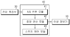
- An A / D conversion module for converting an analog voltage signal output from the voltage measuring unit into a digital voltage signal;
- a central operation module configured to receive a digital voltage signal from the A / D conversion module and determine whether the cell balancing circuit is abnormal.
- the apparatus further includes an abnormality alarm that visually or audibly outputs an abnormal occurrence of the cell balancing circuit, and wherein the controller is configured to perform an abnormality of the cell balancing circuit through the abnormality alarm when an abnormality of the cell balancing circuit occurs. Alert the user visually or audibly.
- an abnormality alarm that visually or audibly outputs an abnormal occurrence of the cell balancing circuit
- the controller is configured to perform an abnormality of the cell balancing circuit through the abnormality alarm when an abnormality of the cell balancing circuit occurs. Alert the user visually or audibly.
- the technical problem of the present invention can be achieved by a battery management system, a battery driving device or a battery pack including the above-described abnormality diagnosis device of the cell balancing circuit.
- a method for diagnosing an abnormality of a cell balancing circuit including a plurality of cell balancing circuits connected to each battery cell so as to balance voltages of a plurality of battery cells included in a battery pack.
- a method for diagnosing an abnormality comprising: turning on a diagnosis target cell balancing switch in a state in which a cell balancing circuit adjacent to a diagnosis target cell balancing circuit is turned off and measuring a voltage difference between the adjacent cell balancing circuits; Turning off the diagnosis target cell balancing switch in a state where the adjacent cell balancing circuit is turned off and measuring a voltage difference between the adjacent cell balancing circuits; And determining whether the diagnosis target cell balancing circuit is abnormal from the voltage difference change pattern of the adjacent cell balancing circuit when the diagnosis target cell balancing circuit is turned on or off.
- a method for diagnosing an abnormality of a cell balancing circuit including: a plurality of cell balancing circuits connected to each battery cell so as to balance voltages of a plurality of battery cells included in a battery pack; A method of diagnosing an abnormality of an entire cell balancing circuit using a discharge resistor and a diagnostic switch provided between a battery cell of a highest potential or the lowest potential and a corresponding cell balancing circuit, wherein the entire cell balancing circuit is turned on or turned off.
- the present invention it is possible to diagnose the abnormality of the cell balancing circuit and the cause of the abnormality with a simple circuit configuration. In addition, even when the entire cell balancing circuit is disconnected or shorted, the cause of the abnormality can be accurately determined. Therefore, it is possible to prevent the battery or the load from being damaged due to an abnormal cell balancing circuit.
- FIG. 1 is a circuit diagram illustrating an apparatus for diagnosing an abnormality of a cell balancing circuit according to a preferred embodiment of the present invention.
- FIG. 2 is a block diagram showing the configuration of a control unit according to a preferred embodiment of the present invention.
- 3 to 5 are diagrams for explaining a method of determining an abnormality and cause of an abnormality of the cell balancing circuit according to an exemplary embodiment of the present invention.
- FIG. 6 is a flowchart illustrating a method for diagnosing an abnormality in a cell balancing circuit according to a preferred embodiment of the present invention.
- FIG. 7 is a flowchart illustrating a method for diagnosing an abnormality of an entire cell balancing circuit according to a preferred embodiment of the present invention.
- FIG. 1 is a circuit diagram illustrating an apparatus for diagnosing an abnormality of a cell balancing circuit according to a preferred embodiment of the present invention. Although only three cells are illustrated in FIG. 1, the present invention is not limited by the number of cells.
- the apparatus for diagnosing an abnormality of a cell balancing circuit may be configured to balance voltages of a plurality of battery cells VB 1 , VB 2 , and VB 3 included in the battery pack 10.
- the voltage measuring unit 30 measuring the voltage difference of the cell balancing circuit 20 corresponding to the battery cells VB 1 , VB 2 , and VB 3 and the adjacent cell balancing circuit measured by the voltage measuring unit 30.
- the cell balancing circuit 20 is a protection circuit of the battery pack 10 balancing the voltages of the battery cells VB 1 , VB 2 , and VB 3 under the control of the controller 40.
- the cell balancing circuit 20 is connected in parallel with a voltage measuring line connected to the positive and negative terminals of each of the battery cells VB 1 , VB 2 , and VB 3 .
- the node connected to one end of the cell balancing circuit 20 and the voltage measurement line extending from the positive terminal of the battery cells VB 1 , VB 2 , and VB 3 is the high potential node A
- the low end node B is the node connected to the other end of the circuit board and the voltage measuring line extending from the negative terminal of the battery cells VB 1 , VB 2 and VB 3 .
- the voltage difference of the cell balancing circuit 20 means the voltage difference between the high potential node A and the low potential node B.
- the high potential node A and the low potential node B are relative points at which the cell balancing circuit 20 and the voltage measuring line are connected.
- the high potential node A and the low potential node B extend in connection with the anode of the first cell VB 1 .
- the point where the cell voltage measuring line and the cell balancing circuit 20 are connected is the high potential node A, and this high potential node A is connected to the cathode of the second cell VB 2 and extended.
- the low potential node B becomes.
- the cell balance circuit 20 includes a battery cell (VB 1, VB 2, VB 3) cell voltage to a discharge resistor (R d) and a battery cell (VB 1, VB 2, VB 3) and the discharge resistance to discharge of the ( R d ) includes a cell balancing switch SW b1 , SW b2 , SW b3 .
- a diode D may be further included at the low potential node B side of the cell balancing circuit 20 to restrict the discharge current and the reverse current from flowing through the discharge resistor R d .
- FET field effect transistor
- the field effect transistor includes a source terminal, a drain terminal, and a gate terminal, and a driving voltage is applied to the gate terminal under the control of the controller 40, and the cell balancing circuit 20 is turned on due to the application of the driving voltage.
- the cell voltage is discharged through the discharge resistor R d .
- the diagnostic resistor R m is a component employed to diagnose an abnormality of the cell balancing switches SW b1 , SW b2 , and SW b3 in the present invention, and through the discharge resistor R d when the cell voltage is discharged.
- a change in the voltage difference of the cell balancing circuit 20 is caused. That is, when the cell balancing switches SW b1 , SW b2 and SW b3 are turned on or the cell balancing switches SW b1 , SW b2 and SW b3 are shorted, a discharge current flows through the discharge loop indicated by the arrow.
- the potential of the high potential node decreases as compared with the case where the discharge current does not flow due to the discharge current flowing through the diagnostic resistance R m at the high potential node side, and the potential of the low potential node has the diagnostic resistance ( The discharge current increases due to the discharge current flowing in R m ) as compared with the case where the discharge current does not flow.
- the voltage difference between nodes of the cell balancing circuit 20 through which the discharge current flows is reduced than when the discharge current does not flow.
- the cell balancing circuit 20 The voltage difference between nodes has the same voltage value as the cell voltage. This is because when the discharge current does not flow in the discharge loop, no voltage drop is generated through the diagnostic resistor R m , and the cell voltage is applied between nodes.
- the voltage measuring unit 30 turns on or off the cell balancing switches SW b1 , SW b2 , and SW b3 under the control of the controller 40 for diagnosing an abnormality of the cell balancing circuit 20.
- the voltage difference between the high potential node A and the low potential node B of the cell balancing circuit 20 is measured and output as an analog voltage signal.
- the voltage measuring unit 30 uses a circuit commonly used to periodically measure the voltage of each of the battery cells VB 1 , VB 2 , and VB 3 . In this case, there is an advantage that it is not necessary to install a separate voltage measuring unit 30 for the purpose of diagnosing the abnormality of the cell balancing circuit 20.
- FIG. 2 is a block diagram showing in more detail the configuration of a control unit according to an embodiment of the present invention.
- the controller 40 includes an A / D conversion module 41, a central operation module 42, and a switch control module 43.
- the A / D conversion module 41 converts an analog voltage signal output from the voltage measuring unit 30 into a digital voltage signal and outputs the digital voltage signal to the central operation module 42.
- the analog voltage signal includes a signal corresponding to the cell voltage of each battery cell VB 1 , VB 2 , VB 3 , and a voltage signal corresponding to the voltage difference of the cell balancing circuit 20.
- the central operation module 42 receives the digital voltage signal from the A / D conversion module 41 and determines whether the cell balancing circuit 20 is abnormal or the cause of the error. That is, the central computing module 42 checks whether the cell balancing circuit 20 to be diagnosed is abnormal or not from the voltage difference pattern of the cell balancing circuit 20 adjacent to the cell balancing circuit 20 to be diagnosed. Determine the cause.
- the switch control module 43 controls the turning on or off of the cell balancing switches SW b1 , SW b2 , and SW b3 included in the cell balancing circuit 20.
- the cell balancing circuit 20 corresponding to the second cell VB 2 may be configured by the apparatus for diagnosing an abnormality of the cell balancing circuit according to an exemplary embodiment of the present invention to determine whether the cell balancing circuit 20 is abnormal or the cause of the abnormality. The following describes the process of diagnosing abnormalities.
- the controller 40 is a cell balancing switch (SW b1 , SW b3 ) of the first cell (VB 1 ) and the third cell (VB 3 ) adjacent to the second cell (VB 2 ) to be diagnosed. ) Is turned off and the cell balancing switch SW b2 of the second cell VB 2 is turned on. Then, the voltage difference between the cell balancing circuit 20 corresponding to the first cell VB 1 and the third cell VB 3 is measured and stored through the voltage measuring unit 30. Then, the controller 40 turns off the cell balancing switch SW b2 of the second cell VB 2 and then corresponds to the first cell VB 1 and the third cell VB 3 .
- SW b1 , SW b3 cell balancing switch
- the voltage difference of the cell balancing circuit 20 is measured and stored through the voltage measuring unit 30.
- the controller 40 temporarily turns on or turns off the cell balancing switch SW b2 of the second cell VB 2 .
- the expression 'Isometric' means controlling the turn on or turn off of the cell balancing switch SW b2 at intervals of time, and the same concept is applied hereafter.
- the controller 40 analyzes the voltage difference change pattern of the cell balancing circuit 20 corresponding to the adjacent cells when the cell balancing switch SW b2 of the second cell VB 2 is turned on or turned off. By determining whether the cell balancing circuit 20 corresponding to the second cell VB 2 is abnormal or the cause of the abnormality.
- the diagnostic target cell balancing circuit is determined to be normal.
- the controller determines that a short circuit occurs in the diagnosis target cell balancing circuit when the voltage difference between the adjacent cell balancing circuits is higher than and equal to the cell voltage when the diagnosis target cell balancing circuit is turned on and when turned off.
- the voltage difference V AB of the cell balancing circuit 20 corresponding to the first cell VB 1 and the third cell VB 3 is the cell balancing switch SW b2 of the second cell VB 2 .
- the controller determines that disconnection has occurred in the diagnostic target cell balancing circuit.
- the disconnection of the cell balancing circuit includes not only the disconnection of the cell balancing switch, but also the case where the discharge resistor Rd is disconnected or the circuit line inside the cell balancing circuit is disconnected. Even in this case, it is apparent that the voltage difference change pattern of the cell balancing circuit adjacent to the diagnosis target cell balancing circuit will show the same pattern as the voltage difference change pattern shown in FIG. 5.
- the apparatus for diagnosing abnormality of the cell balancing circuit according to the present invention may further include an additional circuit configuration capable of accurately diagnosing when the entire cell balancing circuit is shorted or disconnected.
- the apparatus for diagnosing an abnormality of the cell balancing circuit includes a cell balancing circuit 20 connected to a battery cell VB 1 positioned at the lowest potential side and a battery cell corresponding thereto.
- VB 1 may further include a discharge resistor (R z ) and the diagnostic switch (SW z ) provided between.
- the discharge resistor R z and the diagnostic switch SW z may be installed between the cell balancing circuit 20 connected to the battery cell VB3 positioned at the highest potential side and the corresponding battery cell VB 3 . It is self-evident.
- the process of determining whether an abnormality of the cell balancing circuit is abnormal and the cause of the abnormality by the apparatus for diagnosing an abnormality of the cell balancing circuit according to the present invention is as follows.
- the controller 40 may turn on each cell balancing circuit 20 corresponding to each of the battery cells VB 1 , VB 2 , and VB 3 with all cell balancing switches SW b1 , SW b2 , and SW b3 turned on.
- the voltage difference is measured through the voltage measuring unit 30, and the voltage difference of the entire cell balancing circuit 20 is calculated by adding the measured voltage differences to the first order.
- the diagnostic switch SW z is turned on with all cell balancing switches SW b1 , SW b2 , and SW b3 turned on, and then each battery cell VB 1 , VB 2 , VB 3 is turned on in this state.
- the voltage difference of each cell balancing circuit 20 corresponding to is measured through the voltage measuring unit 30, and the measured voltage difference is summed to calculate the voltage difference of the entire cell balancing circuit 20 as the secondary. Then, the controller 40 determines whether or not the voltage difference of the first-order all-cell balancing circuit and the voltage difference of the second-order all-cell balancing circuit are the same, and if it is the same, disconnection occurs in the entire cell balancing circuit. It is determined that it has been done.
- the control unit 40 switches each cell balancing circuit 20 corresponding to each of the battery cells VB 1 , VB 2 , and VB 3 with the entire cell balancing switches SW b1 , SW b2 , and SW b3 turned off. ) Is measured through the voltage measuring unit 30, and the measured voltage difference is added to calculate the voltage difference of the entire cell balancing circuit 20 as the first order. Thereafter, the diagnostic switch SW z is turned on with all cell balancing switches SW b1 , SW b2 , and SW b3 turned off, and then each battery cell VB 1 , VB 2 , VB 3 is turned on in this state.
- the voltage difference of each cell balancing circuit 20 corresponding to) is measured through the voltage measuring unit 30, and the measured voltage difference is added to calculate the voltage difference of the entire cell balancing circuit 20 as a secondary. . Then, the controller 40 determines whether the voltage difference of the total cell balancing circuit calculated second is smaller than the voltage difference of the total cell balancing circuit calculated first, and if it is small, a short circuit occurs in the entire cell balancing circuit. Determine.
- the abnormality diagnosing apparatus of the cell balancing circuit may further include an abnormality alarm 50.
- the controller 40 may notify the outside of the abnormality alarm 50 through the abnormality alarm 50 when the abnormality occurs in the cell balancing circuit 20. That is, when it is determined that there is an abnormality in the cell balancing circuit 20, the control unit 40 transmits an abnormality occurrence signal to the abnormality alarm 50 to notify the fact that the abnormality is visually or audibly through the abnormality alarm 50. Can alarm outside.
- the abnormal alarm 50 includes an LED, an LCD, an alarm alarm or a combination thereof.
- the abnormality alarm 50 may blink an LED, output a warning message to the LCD, or generate an alarm buzzer to notify the user of an abnormality of the cell balancing switch.
- the LED, LCD and alarm alarm is only one example of the abnormal alarm 50, a variety of modified forms of the visual or audio alarm device may be employed as an abnormal alarm is commonly known in the art. Self-explanatory to those who have knowledge.
- the above-described fault diagnosis of the cell balancing circuit may be repeatedly executed at regular intervals or by a diagnosis command automatically generated by a user's diagnosis command or a control algorithm of the controller 40.
- control unit 40 for performing the above-described operation may be configured as a microprocessor capable of executing a code for programming a method of diagnosing an abnormality of the cell balancing circuit, and the logic flow of the control flow of the abnormality diagnosis method of the cell balancing circuit. It can also be configured as a custom-made semiconductor chip (ASIC), but the present invention is not limited thereto.
- ASIC custom-made semiconductor chip
- the abnormality diagnosing apparatus of the cell balancing circuit according to the present invention described above may be used in combination with a battery pack driving apparatus supplied with power from a battery pack.
- the present invention may be included and used in various electronic products that receive a driving voltage from a battery such as a laptop, a mobile phone, and a personal portable multimedia player.
- the present invention may be used in combination with various power units equipped with batteries such as fossil fuel vehicles, electric vehicles, hybrid vehicles, and electric bicycles.
- the apparatus for diagnosing abnormality of the cell balancing circuit according to the present invention may be included and used in a battery management system (BMS) that controls charge / discharge of the battery pack and protects the battery pack from overcharge or overdischarge.
- BMS battery management system
- the abnormality diagnosis apparatus of the cell balancing circuit according to the present invention may be included in the battery pack and used.
- FIG. 6 is a flowchart illustrating a method for diagnosing an abnormality of a cell balancing circuit according to an exemplary embodiment of the present invention.
- to turn on or turn off the cell balancing circuit 20 means to turn on or off the cell balancing switches SW b1 , SW b2 , and SW b3 included in the cell balancing circuit 20.
- step S11 the controller measures and stores a cell voltage of each battery cell through the voltage measuring unit. At this time, the controller turns off the cell balancing circuit corresponding to each battery cell.
- step S12 the controller turns off the cell balancing circuit adjacent to the cell balancing circuit to be diagnosed.
- step S13 the controller turns on the cell balancing circuit to be diagnosed while the adjacent cell balancing circuit is turned off, and measures and stores the voltage difference between the adjacent cell balancing circuits.
- step S14 the controller turns off the cell balancing circuit to be diagnosed while the adjacent cell balancing circuit is turned off, and measures and stores the voltage difference between the adjacent cell balancing circuits.
- step S15 the controller determines whether the cell balancing circuit to be diagnosed is abnormal or the cause of the error from the voltage difference pattern of the adjacent cell balancing circuit when the cell balancing circuit to be diagnosed is turned on or off.
- the controller may determine that the voltage difference between the adjacent cell balancing circuits measured when the cell balancing circuit to be diagnosed is higher than the cell voltage and the adjacent cells measured when the cell balancing circuit to be diagnosed is turned off If the voltage difference of the balancing circuit corresponds to the cell voltage, it is determined that the cell balancing circuit to be diagnosed is normal.
- the controller may generate a short circuit in the cell balancing circuit to be diagnosed when the voltage difference between the adjacent cell balancing circuits measured when the cell balancing circuit to be diagnosed is turned on and when it is turned off is higher than the cell voltage and there is no change. It is determined that it has been done.
- step S16 the controller binarizes the process according to the result of the determination of the abnormality of the cell balancing circuit. If it is determined that no abnormality has occurred in the cell balancing circuit to be diagnosed, the controller terminates the process for diagnosing the abnormality of the cell balancing circuit. On the other hand, if it is determined that an abnormality has occurred in the cell balancing circuit to be diagnosed, the controller shifts the process to step S17, and the abnormality alarm indicates that the abnormality has occurred in the cell balancing circuit to be diagnosed in step S17. Alert the user visually or audibly through.
- Steps S11 to S17 described above may be performed for each cell balancing circuit corresponding to each battery cell.
- the abnormality diagnosis of the cell balancing circuit may be repeatedly performed at regular intervals, and may be performed by a diagnosis command automatically generated by a user's diagnosis command or a control algorithm of the controller.
- FIG. 7 is a flowchart illustrating a method of diagnosing an abnormality of the entire cell balancing circuit.
- step S21 the controller measures the voltage difference of each cell balancing circuit through the voltage measuring unit while turning on the whole cell balancing circuit and turning off the diagnostic switch, and summing each measured voltage difference to total cell balancing.
- the voltage difference of the circuit is calculated first.
- step S22 the controller turns on the diagnostic switch with the entire cell balancing circuit turned on, measures the voltage difference of each cell balancing circuit through a voltage measuring unit, and adds each measured voltage difference to the voltage of the entire cell balancing circuit. Calculate the difference two times.
- step S23 the control unit compares the voltage difference of the first cell calculation circuit calculated with the primary and the voltage difference of the cell balancing circuit calculated second. If the two voltage difference values are the same, the controller determines that disconnection has occurred in the entire cell balancing circuit.
- step S24 the control unit binaries the process according to the abnormal diagnosis result of the whole cell balancing circuit. If it is determined that disconnection has occurred in the entire cell balancing circuit, the process proceeds to step S29, and the user is visually or audibly notified to the user that the disconnection has occurred in the entire cell balancing circuit. On the other hand, if it is determined that no disconnection has occurred in the entire cell balancing circuit, the process proceeds to step S25.
- step S25 the controller measures the voltage difference of each cell balancing circuit through the voltage measuring unit in a state where the diagnostic switch is turned off and the whole cell balancing circuit is turned off.
- the voltage difference of the cell balancing circuit is calculated first.
- step S26 the controller turns on the diagnostic switch with the entire cell balancing circuit turned off, measures the voltage difference of each cell balancing circuit through the voltage measuring unit, and adds each measured voltage difference to the total cell balancing circuit. The voltage difference is calculated second.
- step S27 the control unit compares the voltage difference of the first cell calculation circuit and the second cell calculation circuit. If the voltage difference of the total cell balancing circuit calculated second is smaller than the voltage difference of the total cell balancing circuit calculated first, it is determined that a short circuit occurs in the entire cell balancing circuit.
- step S28 the controller binaryizes the process according to the abnormal diagnosis result of the entire cell balancing circuit. If it is determined that a short circuit has occurred in the entire cell balancing circuit, the process proceeds to step S29, in which the user is visually or audibly notified to the user through the abnormality alarm that the short circuit has occurred in the entire cell balancing circuit. On the other hand, if it is determined that a short circuit has not occurred in the entire cell balancing circuit, the controller terminates the abnormal diagnosis process of the entire cell balancing circuit.
- the method of diagnosing an abnormality of the cell balancing circuit according to the present invention may be repeatedly performed at regular intervals while the battery pack is in use, or may be executed by a diagnostic command automatically generated by a user's diagnostic command or a control algorithm of a controller.
- the structure which outputs the abnormality diagnosis result of a cell balancing circuit to an abnormality alarm may be abbreviate
- the controller stores and stores the abnormal diagnosis result and the cause of the error in a memory.
- the present invention is not limited to the turn-on or turn-off order of the cell balancing circuit and the diagnostic switch, the turn-on or turn-off order of the cell balancing circuit and the diagnostic switch described in the embodiment is within the scope of not changing the technical spirit of the present invention. It can be changed arbitrarily.
Abstract
Description
Claims (25)
- 배터리 팩에 포함된 복수의 배터리 셀의 전압을 밸런싱할 수 있도록 각 배터리 셀과 연결된 복수의 셀 밸런싱 회로;상기 셀 밸런싱 회로와 대응하는 배터리 셀의 양극과 음극 단자 사이에 각각 설치된 진단저항;각 배터리 셀에 대응하는 셀 밸런싱 회로의 전압차를 측정하는 전압 측정부; 및진단 대상이 되는 셀 밸런싱 회로를 턴온 또는 턴오프시키고, 상기 전압 측정부를 통해 측정된 인접하는 셀 밸런싱 회로의 전압차에 대한 변화 패턴으로부터 상기 진단 대상이 되는 셀 밸런싱 회로의 이상 여부를 판별하는 제어부를 포함하는 것을 특징으로 하는 셀 밸런싱 회로의 이상 진단 장치.
- 제1항에 있어서, 상기 인접하는 셀 밸런싱 회로의 전압차는,상기 인접하는 셀 밸런싱 회로의 일단과 대응하는 배터리 셀의 음극 단자가 연결된 저전위 노드와 상기 인접하는 셀 밸런싱 회로의 타단과 대응하는 배터리 셀의 양극 단자가 연결된 고전위 노드 사이의 전압차인 것을 특징으로 하는 셀 밸런싱 회로의 이상 진단 장치.
- 제1항에 있어서, 상기 셀 밸런싱 회로는,대응하는 배터리 셀의 전압을 방전시키는 방전저항; 및상기 대응하는 배터리 셀과 상기 방전저항을 연결 또는 해제하는 셀 밸런싱 스위치를 포함하고,상기 제어부는 상기 셀 밸런싱 스위치의 턴온 또는 턴오프를 제어하여 배터리 셀의 전압을 밸런싱하는 것을 특징으로 하는 셀 밸런싱 회로의 이상 진단 장치.
- 제3항에 있어서,상기 셀 밸런싱 회로는 방전전류와 역방향의 전류가 상기 방전저항을 통해 흐르는 것을 제한하는 다이오드를 더 포함하는 것을 특징으로 하는 셀 밸런싱 회로의 이상 진단 장치.
- 제3항에 있어서,상기 셀 밸런싱 스위치는 전계 효과 트랜지스터(field effect transistor; FET)인 것을 특징으로 하는 셀 밸런싱 회로의 이상 진단 장치.
- 제1항에 있어서, 상기 제어부는,상기 인접하는 셀 밸런싱 회로를 턴오프시킨 상태에서 상기 진단 대상이 되는 셀 밸런싱 회로를 턴온 또는 턴오프시키고,상기 전압 측정부를 통해 상기 진단 대상 셀 밸런싱 회로가 턴온 또는 턴오프되었을 때 상기 인접하는 셀 밸런싱 회로의 전압차를 측정하는 것을 특징으로 하는 셀 밸런싱 회로의 이상 진단 장치.
- 제1항 또는 제6항에 있어서, 상기 제어부는,상기 진단 대상 셀 밸런싱 회로가 턴온 상태일 때 상기 인접하는 셀 밸런싱 회로의 전압차가 셀 전압보다 높고, 상기 진단 대상 셀 밸런싱 회로가 턴오프 상태일 때 상기 인접하는 셀 밸런싱 회로의 전압차가 셀 전압에 대응하면, 상기 진단 대상 셀 밸런싱 회로가 정상인 것으로 판별하는 것을 특징으로 하는 셀 밸런싱 회로의 이상 진단 장치.
- 제1항 또는 제6항에 있어서, 상기 제어부는,상기 진단 대상 셀 밸런싱 회로가 턴온 상태일 때와 턴오프 상태일 때 상기 인접하는 셀 밸런싱 회로의 전압차가 셀 전압과 대응하면, 상기 진단 대상 셀 밸런싱 회로에 단선이 발생된 것으로 판별하는 것을 특징으로 하는 셀 밸런싱 회로의 이상 진단 장치.
- 제1항 또는 제6항에 있어서, 상기 제어부는,상기 진단 대상 셀 밸런싱 회로가 턴온 상태일 때와 턴오프상태일 때 상기 인접하는 셀 밸런싱 회로의 전압차가 셀 전압보다 높으면 상기 진단 대상 셀 밸런싱 회로에 단락이 발생된 것으로 판별하는 것을 특징으로 하는 셀 밸런싱 회로의 이상 진단 장치.
- 배터리 팩에 포함된 복수의 배터리 셀의 전압을 밸런싱할 수 있도록 각 배터리 셀과 연결된 복수의 셀 밸런싱 회로;각 배터리 셀에 대응하는 셀 밸런싱 회로의 전압차를 측정하는 전압 측정부;최고전위 또는 최저전위 측 배터리 셀과 이와 대응하는 셀 밸런싱 회로 사이에 설치된 방전저항과 진단 스위치; 및전체 셀 밸런싱 회로의 턴온 또는 턴오프 상태에서 상기 진단 스위치를 턴온 또는 턴오프시키고, 상기 진단 스위치의 턴온 상태와 턴오프 상태에서 상기 전압 측정부를 통해 측정된 전체 셀 밸런싱 회로의 전압차에 대한 변화 패턴으로부터 전체 셀 밸런싱 회로의 이상 여부를 진단하는 제어부를 포함하는 것을 특징으로 하는 셀 밸런싱 회로의 이상 진단 장치.
- 제10항에 있어서, 상기 제어부는,상기 전체 셀 밸런싱 회로를 턴온시킨 상태에서, 상기 진단 스위치를 턴온시켰을 때의 상기 전체 셀 밸런싱 회로의 전압차와 상기 진단 스위치를 턴오프시켰을 때의 상기 전체 셀 밸런싱 회로의 전압차가 전체 셀 전압과 대응하면 상기 전체 셀 밸런싱 회로에 단선이 발생된 것으로 판별하는 것을 특징으로 하는 셀 밸런싱 회로의 이상 진단 장치.
- 제10항에 있어서, 상기 제어부는,상기 전체 셀 밸런싱 회로를 턴오프시킨 상태에서, 상기 진단 스위치를 턴온시켰을 때의 상기 전체 셀 밸런싱 회로의 전압차보다 상기 진단 스위치를 턴오프시켰을 때의 상기 전체 셀 밸런싱 회로의 전압차가 낮으면 상기 전체 셀 밸런싱 회로에 단락이 발생된 것으로 판별하는 것을 특징으로 하는 셀 밸런싱 회로의 이상 진단 장치.
- 제1항 또는 제10항에 있어서,상기 제어부는,상기 셀 밸런싱 회로에 포함된 셀 밸런싱 스위치의 동작을 제어하는 스위치 제어 모듈;상기 전압 측정부로부터 출력되는 아날로그 전압 신호를 디지털 전압 신호로 변환하는 A/D 변환 모듈; 및상기 A/D 변환 모듈로부터 디지털 전압 신호를 입력 받아 상기 셀 밸런싱 회로의 이상 여부를 판별하는 중앙 연산 모듈을 포함하는 것을 특징으로 하는 셀 밸런싱 회로의 이상 진단 장치.
- 제1항 또는 제10항에 있어서,상기 셀 밸런싱 회로의 이상 발생 사실을 시각적 또는 청각적으로 출력하는 이상 경보기를 더 포함하고,상기 제어부는 상기 셀 밸런싱 회로의 이상이 발생된 경우 상기 이상 경보기를 통해 상기 셀 밸런싱 회로의 이상 발생 사실을 시각적 또는 청각적으로 경보하는 것을 특징으로 하는 셀 밸런싱 회로의 이상 진단 장치.
- 제1항 내지 제14항 중 어느 한 항에 따른 셀 밸런싱 회로의 이상 진단 장치를 포함하는 배터리 관리 시스템.
- 제1항 내지 제14항 중 어느 한 항에 따른 셀 밸런싱 회로의 이상 진단 장치를 포함하는 배터리 구동 장치.
- 제1항 내지 제14항 중 어느 한 항에 따른 셀 밸런싱 회로의 이상 진단 장치를 포함하는 배터리 팩.
- 배터리 팩에 포함된 복수의 배터리 셀의 전압을 밸런싱할 수 있도록 각 배터리 셀과 연결된 복수의 셀 밸런싱 회로의 이상을 진단하는 방법에 있어서,진단 대상 셀 밸런싱 회로와 인접하는 셀 밸런싱 회로를 턴오프시킨 상태에서 상기 진단 대상 셀 밸런싱 스위치를 턴온시키고 상기 인접하는 셀 밸런싱 회로의 전압차를 측정하는 단계;상기 인접하는 셀 밸런싱 회로를 턴오프시킨 상태에서 상기 진단 대상 셀 밸런싱 스위치를 턴오프시키고 상기 인접하는 셀 밸런싱 회로의 전압차를 측정하는 단계; 및상기 진단 대상 셀 밸런싱 회로의 턴온 또는 턴오프 시 상기 인접하는 셀 밸런싱 회로의 전압차에 대한 변화 패턴으로부터 상기 진단 대상 셀 밸런싱 회로의 이상 여부를 판별하는 단계를 포함하는 것을 특징으로 하는 셀 밸런싱 회로의 이상 진단 방법.
- 제18항에 있어서, 상기 셀 밸런싱 회로의 이상 여부를 판별하는 단계는,상기 진단 대상 셀 밸런싱 회로가 턴온 상태에서 측정된 상기 인접하는 셀 밸런싱 회로의 전압차보다 상기 진단 대상 셀 밸런싱 회로가 턴오프 상태에서 측정된 상기 인접하는 셀 밸런싱 회로의 전압차가 낮으면 상기 진단 대상 셀 밸런싱 회로가 정상인 것으로 판별하는 것을 특징으로 하는 셀 밸런싱 회로의 이상 진단 방법.
- 제18항에 있어서, 상기 셀 밸런싱 회로의 이상 여부를 판별하는 단계는,상기 진단 대상 셀 밸런싱 회로가 턴온 상태에서 측정된 상기 인접하는 셀 밸런싱 회로의 전압차와 상기 진단 대상 셀 밸런싱 회로가 턴오프 상태에서 측정된 상기 인접하는 셀 밸런싱 회로의 전압차가 셀 전압과 대응하면 상기 진단 대상 셀 밸런싱 회로에 단선이 발생된 것으로 판별하는 것을 특징으로 하는 셀 밸런싱 회로의 이상 진단 방법.
- 제18항에 있어서, 상기 셀 밸런싱 회로의 이상 여부를 판별하는 단계는,상기 진단 대상 셀 밸런싱 회로가 턴온 상태에서 측정된 상기 인접하는 셀 밸런싱 회로의 전압차와 상기 진단 대상 셀 밸런싱 회로가 턴오프 상태에서 측정된 상기 인접하는 셀 밸런싱 회로의 전압차가 셀 전압보다 높으면 상기 진단 대상 셀 밸런싱 회로에 단락이 발생된 것으로 판별하는 것을 특징으로 하는 셀 밸런싱 회로의 이상 진단 방법.
- 배터리 팩에 포함된 복수의 배터리 셀의 전압을 밸런싱할 수 있도록 각 배터리 셀과 연결된 복수의 셀 밸런싱 회로와, 최고전위 또는 최저전위 측 배터리 셀과 이와 대응하는 셀 밸런싱 회로 사이에 설치된 방전저항과 진단 스위치를 이용하여 전체 셀 밸런싱 회로의 이상을 진단하는 방법에 있어서,전체 셀 밸런싱 회로를 턴온 또는 턴오프시킨 상태에서 상기 진단 스위치를 턴온 또는 턴오프시켰을 때 상기 전체 셀 밸런싱 회로의 전압차를 측정하는 단계; 및상기 진단 스위치를 턴온 또는 턴오프시켰을 때, 상기 전체 셀 밸런싱 회로의 전압차에 대한 변화 패턴으로부터 상기 전체 셀 밸런싱 회로의 이상 여부를 판별하는 단계를 포함하는 것을 특징으로 하는 셀 밸런싱 회로의 이상 진단 방법.
- 제22항에 있어서, 상기 전체 셀 밸런싱 회로의 이상 여부를 판별하는 단계는,상기 전체 셀 밸런싱 회로를 턴온시킨 상태에서, 상기 진단 스위치를 턴온시켰을 때의 상기 전체 셀 밸런싱 회로의 전압차와 상기 진단 스위치를 턴오프시켰을 때의 상기 전체 셀 밸런싱 회로의 전압차가 전체 셀 전압과 대응하면 상기 전체 셀 밸런싱 회로에 단선이 발생된 것으로 판별하는 것을 특징으로 하는 셀 밸런싱 회로의 이상 진단 방법.
- 제22항에 있어서, 상기 전체 셀 밸런싱 회로의 이상 여부를 판별하는 단계는,상기 전체 셀 밸런싱 회로를 턴오프시킨 상태에서, 상기 진단 스위치를 턴오프시켰을 때의 상기 전체 셀 밸런싱 회로의 전압차보다 상기 진단 스위치를 턴온시켰을 때의 상기 전체 셀 밸런싱 회로의 전압차가 낮으면 상기 전체 셀 밸런싱 회로에 단락이 발생된 것으로 판별하는 특징으로 하는 셀 밸런싱 회로의 이상 진단 방법.
- 제18항 또는 제22항에 있어서,상기 셀 밸런싱 회로의 이상이 발생된 것으로 판별되면, 상기 셀 밸런싱 회로의 이상 발생 사실을 시각적 또는 청각적으로 경보하는 단계를 더 포함하는 것을 특징으로 하는 셀 밸런싱 회로의 이상 진단 방법.
Priority Applications (4)
| Application Number | Priority Date | Filing Date | Title |
|---|---|---|---|
| JP2012503342A JP5101748B2 (ja) | 2010-03-05 | 2010-08-23 | セルバランス回路の異常診断装置及び方法 |
| CN201080066551.8A CN102884438B (zh) | 2010-03-05 | 2010-08-23 | 用于诊断电池胞平衡电路中的异常的设备和方法 |
| EP10847086.5A EP2544013B1 (en) | 2010-03-05 | 2010-08-23 | Abnormality diagnostic device and method of cell balancing circuits |
| US13/195,578 US8902072B2 (en) | 2010-03-05 | 2011-08-01 | Apparatus and method for diagnosing abnormality in cell balancing circuit |
Applications Claiming Priority (2)
| Application Number | Priority Date | Filing Date | Title |
|---|---|---|---|
| KR10-2010-0019924 | 2010-03-05 | ||
| KR1020100019924A KR101256952B1 (ko) | 2010-03-05 | 2010-03-05 | 셀 밸런싱부의 고장 진단 장치 및 방법 |
Related Child Applications (1)
| Application Number | Title | Priority Date | Filing Date |
|---|---|---|---|
| US13/195,578 Continuation US8902072B2 (en) | 2010-03-05 | 2011-08-01 | Apparatus and method for diagnosing abnormality in cell balancing circuit |
Publications (1)
| Publication Number | Publication Date |
|---|---|
| WO2011108788A1 true WO2011108788A1 (ko) | 2011-09-09 |
Family
ID=44542408
Family Applications (1)
| Application Number | Title | Priority Date | Filing Date |
|---|---|---|---|
| PCT/KR2010/005583 WO2011108788A1 (ko) | 2010-03-05 | 2010-08-23 | 셀 밸런싱 회로의 이상 진단 장치 및 방법 |
Country Status (6)
| Country | Link |
|---|---|
| US (1) | US8902072B2 (ko) |
| EP (2) | EP2730933B1 (ko) |
| JP (2) | JP5101748B2 (ko) |
| KR (1) | KR101256952B1 (ko) |
| CN (2) | CN102884438B (ko) |
| WO (1) | WO2011108788A1 (ko) |
Families Citing this family (46)
| Publication number | Priority date | Publication date | Assignee | Title |
|---|---|---|---|---|
| US8819162B2 (en) | 2012-05-07 | 2014-08-26 | Tesla Motors, Inc. | Host communications architecture |
| KR101944842B1 (ko) * | 2012-08-21 | 2019-02-01 | 에스케이이노베이션 주식회사 | 셀 밸런싱 회로의 고장 진단 장치 |
| KR101953907B1 (ko) * | 2012-11-14 | 2019-03-04 | 현대모비스 주식회사 | 모듈 전압 센싱을 이용한 센싱 라인 단선 검출 시간 단축 장치 및 방법 |
| FR2998729B1 (fr) * | 2012-11-27 | 2015-01-30 | Renault Sa | Procede d'equilibrage de la tension aux bornes de cellules d'une batterie d'un vehicule automobile electrique ou hybride. |
| JP5502183B1 (ja) * | 2012-12-06 | 2014-05-28 | 三菱電機株式会社 | バッテリーマネジメント装置 |
| KR101589198B1 (ko) * | 2013-02-19 | 2016-01-28 | 주식회사 엘지화학 | 셀 밸런싱 회로의 고장 진단 장치 및 방법 |
| KR101309009B1 (ko) * | 2013-02-28 | 2013-10-04 | 주식회사 씨엔에이치시스템 | 순간정전 보상장치 및 방법 |
| US9176197B2 (en) * | 2013-07-22 | 2015-11-03 | GM Global Technology Operations LLC | Battery sensing circuit path resistance compensation systems and methods |
| JP5989620B2 (ja) * | 2013-09-17 | 2016-09-07 | 株式会社東芝 | 組電池モジュール及び断線検出方法 |
| JP6016754B2 (ja) * | 2013-11-15 | 2016-10-26 | オムロンオートモーティブエレクトロニクス株式会社 | 組電池電圧検出装置 |
| WO2015136320A1 (en) * | 2014-03-10 | 2015-09-17 | Changs Ascending Enterprise Co., Ltd. | State of health determination without unnoticed battery shut down |
| JP5928509B2 (ja) | 2014-03-12 | 2016-06-01 | トヨタ自動車株式会社 | 電池監視装置 |
| DE102014214984A1 (de) | 2014-07-30 | 2016-02-04 | Robert Bosch Gmbh | Kurzschlussschutzvorrichtung |
| US20160072156A1 (en) * | 2014-09-09 | 2016-03-10 | Chao-Cheng Lu | Universal cell |
| JP6558204B2 (ja) * | 2015-10-21 | 2019-08-14 | 株式会社デンソー | 異常判定装置 |
| KR102523045B1 (ko) | 2016-01-12 | 2023-04-17 | 삼성전자주식회사 | 고장 셀 검출 장치 및 방법 |
| CN105676137B (zh) * | 2016-01-18 | 2019-04-02 | 廖德成 | 一种高速电池电压扫描电路 |
| TWI811718B (zh) | 2016-03-16 | 2023-08-11 | 澳門商創科(澳門離岸商業服務)有限公司 | 具有無線通訊的電動工具蓄電池組 |
| JP6477593B2 (ja) * | 2016-05-16 | 2019-03-06 | 株式会社デンソー | 組電池監視システム |
| KR102025286B1 (ko) | 2016-07-12 | 2019-09-26 | 주식회사 엘지화학 | 배터리 셀 밸런싱의 방법 및 시스템 |
| CN106249099B (zh) * | 2016-08-26 | 2018-12-07 | 北京海博思创科技有限公司 | 电压采集线开路故障检测设备和方法及电池管理系统 |
| DE102016216775A1 (de) | 2016-09-05 | 2018-03-08 | Bayerische Motoren Werke Aktiengesellschaft | Verfahren zum Überprüfen einer Symmetrierschaltung |
| WO2018056262A1 (ja) * | 2016-09-21 | 2018-03-29 | オートモーティブエナジーサプライ株式会社 | 電源システム |
| KR102168910B1 (ko) * | 2016-09-21 | 2020-10-22 | 가부시키가이샤 인비젼 에이이에스씨 재팬 | 전원 시스템 |
| DE102016218516A1 (de) | 2016-09-27 | 2018-03-29 | Robert Bosch Gmbh | Elektrisches Energiespeichersystem mit einer über eine Diode mit einem Stromerfassungsmittel elektrisch leitend verbundenen Querverbindung mehrerer paralleler Energiespeicherstränge und Verfahren zur Detektion eines Leitungsfehlers |
| CN106786944B (zh) * | 2016-12-31 | 2020-12-18 | 华为技术有限公司 | 一种串联电池组单体电池的采样电路、均衡电路及系统 |
| CN106501703B (zh) * | 2017-01-04 | 2019-04-16 | 山东谦恒电子科技有限公司 | Bms均衡mos管检测方法及装置 |
| KR102345507B1 (ko) * | 2017-01-24 | 2021-12-29 | 삼성에스디아이 주식회사 | 배터리 팩 및 배터리 팩이 연결된 차량 |
| KR102202613B1 (ko) * | 2017-09-27 | 2021-01-12 | 주식회사 엘지화학 | 배터리 모듈 균등화 장치, 이를 포함하는 배터리 팩 및 자동차 |
| KR102236384B1 (ko) * | 2017-10-27 | 2021-04-05 | 주식회사 엘지화학 | 배터리 밸런싱을 위한 장치 및 그것을 포함하는 배터리팩 |
| KR102256099B1 (ko) * | 2017-11-29 | 2021-05-25 | 주식회사 엘지에너지솔루션 | 배터리 팩 |
| KR102055850B1 (ko) | 2017-12-21 | 2019-12-13 | 주식회사 엘지화학 | 전류 센서 진단 장치 및 방법 |
| JP7081225B2 (ja) * | 2018-03-12 | 2022-06-07 | 株式会社デンソー | 電池監視装置 |
| KR102469820B1 (ko) * | 2018-06-08 | 2022-11-21 | 주식회사 엘지에너지솔루션 | 전기 부하를 위한 구동 장치, 그것을 포함하는 전기 자동차 및 전기 부하의 오픈 고장을 검출하는 방법 |
| KR102591107B1 (ko) * | 2018-08-10 | 2023-10-17 | 주식회사 엘지에너지솔루션 | 전기 부하를 위한 구동 장치, 그것을 포함하는 전기 자동차 및 전기 부하를 구동하기 위한 방법 |
| KR102443667B1 (ko) * | 2018-10-26 | 2022-09-14 | 주식회사 엘지에너지솔루션 | 밸런싱 장치, 및 그것을 포함하는 배터리 관리 시스템과 배터리팩 |
| TWI683502B (zh) * | 2018-11-22 | 2020-01-21 | 美律實業股份有限公司 | 充電裝置及其操作方法 |
| KR102437323B1 (ko) * | 2019-01-11 | 2022-08-26 | 주식회사 엘지에너지솔루션 | 배터리 팩 진단 장치 |
| US11418041B2 (en) * | 2019-03-15 | 2022-08-16 | Lg Energy Solution, Ltd. | Battery system |
| KR20210011236A (ko) * | 2019-07-22 | 2021-02-01 | 주식회사 엘지화학 | 배터리 저항 진단 장치 및 방법 |
| KR102317074B1 (ko) | 2019-10-01 | 2021-10-25 | 현대모비스 주식회사 | 과전류 및 저전류 보호회로를 구비한 배터리 모니터링 시스템 및 그것의 과전류 및 저전류 보호 방법 |
| EP3822645B1 (en) | 2019-11-18 | 2022-10-26 | Volvo Car Corporation | System and method for detecting failures in a battery management system for a vehicle battery |
| US11545841B2 (en) * | 2019-11-18 | 2023-01-03 | Semiconductor Components Industries, Llc | Methods and apparatus for autonomous balancing and communication in a battery system |
| US11262408B2 (en) * | 2020-02-24 | 2022-03-01 | Ford Global Technologies, Llc | Vehicle traction battery over-discharge diagnosing method and assembly |
| KR102368977B1 (ko) * | 2020-02-25 | 2022-03-02 | 삼성에스디아이 주식회사 | 배터리 관리 장치 |
| EP4258508A1 (en) * | 2022-04-04 | 2023-10-11 | GE Aviation Systems Limited | System and method for battery management |
Citations (5)
| Publication number | Priority date | Publication date | Assignee | Title |
|---|---|---|---|---|
| JP2002354684A (ja) * | 2001-05-25 | 2002-12-06 | Toyota Motor Corp | 二次電池制御装置 |
| JP2004266992A (ja) * | 2003-02-10 | 2004-09-24 | Denso Corp | 組電池の放電装置 |
| JP2006294339A (ja) * | 2005-04-07 | 2006-10-26 | Shin Kobe Electric Mach Co Ltd | 電池モジュール |
| JP2007085847A (ja) | 2005-09-21 | 2007-04-05 | Hitachi Vehicle Energy Ltd | セルバランス回路異常検出方式 |
| JP2008175804A (ja) * | 2006-12-18 | 2008-07-31 | Nissan Motor Co Ltd | 異常診断装置 |
Family Cites Families (15)
| Publication number | Priority date | Publication date | Assignee | Title |
|---|---|---|---|---|
| JP4605952B2 (ja) * | 2001-08-29 | 2011-01-05 | 株式会社日立製作所 | 蓄電装置及びその制御方法 |
| JP3615507B2 (ja) * | 2001-09-28 | 2005-02-02 | 三洋電機株式会社 | 組電池の充電率調整回路 |
| US20050269989A1 (en) * | 2004-06-05 | 2005-12-08 | Geren Michael D | Cell balancing circuit |
| KR101014981B1 (ko) * | 2005-07-07 | 2011-02-16 | 가부시끼가이샤 도시바 | 전지 모듈 |
| EP1936777B1 (en) * | 2006-12-18 | 2017-11-01 | Nissan Motor Ltd. | Abnormality Diagnostic Device |
| KR100993110B1 (ko) * | 2007-07-26 | 2010-11-08 | 주식회사 엘지화학 | 배터리 셀의 충전량 밸런싱 장치 및 방법 |
| JP5127383B2 (ja) * | 2007-09-28 | 2013-01-23 | 株式会社日立製作所 | 電池用集積回路および該電池用集積回路を使用した車両用電源システム |
| JP5459946B2 (ja) | 2007-09-28 | 2014-04-02 | 株式会社日立製作所 | 車両用直流電源装置 |
| JP5250230B2 (ja) * | 2007-09-28 | 2013-07-31 | 株式会社日立製作所 | 車両用電源システムおよび電池セル制御用集積回路 |
| JP5224095B2 (ja) * | 2007-12-27 | 2013-07-03 | 株式会社Gsユアサ | 組電池の電池管理装置 |
| JP5549121B2 (ja) * | 2008-06-17 | 2014-07-16 | 三洋電機株式会社 | 組電池の電圧検出装置及びこれを具えたバッテリシステム |
| JP2010029050A (ja) | 2008-07-24 | 2010-02-04 | Toshiba Corp | 電池システム |
| JP5254714B2 (ja) * | 2008-09-05 | 2013-08-07 | 株式会社マキタ | 電動工具用マイコン搭載システム及び電池パック |
| JP5221468B2 (ja) * | 2009-02-27 | 2013-06-26 | 株式会社日立製作所 | 電池監視装置 |
| US8324861B2 (en) * | 2009-03-05 | 2012-12-04 | O2Micro Inc. | Multi-channel converter with self-diagnosis functionality |
-
2010
- 2010-03-05 KR KR1020100019924A patent/KR101256952B1/ko active IP Right Grant
- 2010-08-23 CN CN201080066551.8A patent/CN102884438B/zh active Active
- 2010-08-23 EP EP14151199.8A patent/EP2730933B1/en active Active
- 2010-08-23 CN CN201510239038.9A patent/CN104931841B/zh active Active
- 2010-08-23 EP EP10847086.5A patent/EP2544013B1/en active Active
- 2010-08-23 WO PCT/KR2010/005583 patent/WO2011108788A1/ko active Application Filing
- 2010-08-23 JP JP2012503342A patent/JP5101748B2/ja active Active
-
2011
- 2011-08-01 US US13/195,578 patent/US8902072B2/en active Active
-
2012
- 2012-06-26 JP JP2012143313A patent/JP5356579B2/ja active Active
Patent Citations (5)
| Publication number | Priority date | Publication date | Assignee | Title |
|---|---|---|---|---|
| JP2002354684A (ja) * | 2001-05-25 | 2002-12-06 | Toyota Motor Corp | 二次電池制御装置 |
| JP2004266992A (ja) * | 2003-02-10 | 2004-09-24 | Denso Corp | 組電池の放電装置 |
| JP2006294339A (ja) * | 2005-04-07 | 2006-10-26 | Shin Kobe Electric Mach Co Ltd | 電池モジュール |
| JP2007085847A (ja) | 2005-09-21 | 2007-04-05 | Hitachi Vehicle Energy Ltd | セルバランス回路異常検出方式 |
| JP2008175804A (ja) * | 2006-12-18 | 2008-07-31 | Nissan Motor Co Ltd | 異常診断装置 |
Non-Patent Citations (1)
| Title |
|---|
| See also references of EP2544013A4 * |
Also Published As
| Publication number | Publication date |
|---|---|
| EP2544013B1 (en) | 2015-03-25 |
| CN102884438A (zh) | 2013-01-16 |
| EP2730933A1 (en) | 2014-05-14 |
| JP5101748B2 (ja) | 2012-12-19 |
| JP5356579B2 (ja) | 2013-12-04 |
| CN104931841B (zh) | 2018-01-02 |
| KR101256952B1 (ko) | 2013-04-25 |
| CN102884438B (zh) | 2016-03-02 |
| EP2730933B1 (en) | 2018-04-18 |
| US20110285538A1 (en) | 2011-11-24 |
| US8902072B2 (en) | 2014-12-02 |
| JP2012515354A (ja) | 2012-07-05 |
| KR20110100863A (ko) | 2011-09-15 |
| EP2544013A4 (en) | 2013-07-31 |
| CN104931841A (zh) | 2015-09-23 |
| EP2544013A1 (en) | 2013-01-09 |
| JP2012255788A (ja) | 2012-12-27 |
Similar Documents
| Publication | Publication Date | Title |
|---|---|---|
| WO2011108788A1 (ko) | 셀 밸런싱 회로의 이상 진단 장치 및 방법 | |
| WO2011102576A1 (ko) | 셀 밸런싱 회로의 이상 진단 장치 및 방법 | |
| US10895603B2 (en) | Voltage monitoring module and voltage monitoring system to detect a current leakage | |
| WO2014129757A1 (ko) | 셀 밸런싱 회로의 고장 진단 장치 및 방법 | |
| WO2013147494A1 (ko) | 배터리의 절연 저항 측정 장치 및 방법 | |
| WO2020076127A1 (ko) | 배터리 관리 장치 및 방법 | |
| WO2011083993A2 (ko) | 배터리 제어 장치 및 방법 | |
| CN107576878B (zh) | 异常检测装置以及电池组系统 | |
| WO2013119070A1 (ko) | 양방향 디씨-디씨 컨버터를 이용한 배터리 관리 시스템의 셀 밸런싱 회로 장치 | |
| WO2014084628A1 (ko) | 배터리 전류 측정 장치 및 그 방법 | |
| WO2018074744A1 (ko) | 전압 분배를 이용한 스위치 진단 장치 및 방법 | |
| KR20100023364A (ko) | 부동 캐패시터를 이용한 셀 밸런싱 회로의 고장 진단 장치 및 방법 | |
| WO2022080709A1 (ko) | 릴레이 진단 장치, 릴레이 진단 방법, 배터리 시스템, 및 전기 차량 | |
| WO2022025725A1 (ko) | 배터리 관리 장치, 배터리 팩, 배터리 시스템 및 배터리 관리 방법 | |
| KR101065562B1 (ko) | 셀 밸런싱 스위치의 고장 진단 장치 및 방법 | |
| WO2023063625A1 (ko) | 배터리 진단 장치, 배터리 팩, 전기 차량, 및 배터리 진단 방법 | |
| WO2022019600A1 (ko) | 이상 셀 진단 방법 및 이를 적용한 배터리 시스템 | |
| WO2021066394A1 (ko) | 병렬 연결 셀의 연결 고장 검출 방법 및 시스템 | |
| WO2015122746A1 (ko) | 고장 발생 여부의 분석이 가능한 신호를 출력하는 배터리 관리 시스템 및 이를 포함하는 배터리 구동 시스템 | |
| WO2020076126A1 (ko) | 배터리 관리 장치 및 방법 | |
| KR20210104458A (ko) | 배터리 장치 및 전류 센서 진단 방법 | |
| WO2021049753A1 (ko) | 배터리 진단 장치 및 방법 | |
| WO2023132604A1 (ko) | 융착 진단 방법 및 이를 이용한 배터리 시스템 | |
| WO2023113159A1 (ko) | 릴레이 진단 장치 및 릴레이 진단 방법 | |
| WO2023153608A1 (ko) | 전류센서 진단 방법, 그 방법을 제공하는 전류센서 진단 시스템 및 배터리 시스템 |
Legal Events
| Date | Code | Title | Description |
|---|---|---|---|
| WWE | Wipo information: entry into national phase |
Ref document number: 201080066551.8 Country of ref document: CN |
|
| WWE | Wipo information: entry into national phase |
Ref document number: 2012503342 Country of ref document: JP |
|
| 121 | Ep: the epo has been informed by wipo that ep was designated in this application |
Ref document number: 10847086 Country of ref document: EP Kind code of ref document: A1 |
|
| NENP | Non-entry into the national phase |
Ref country code: DE |
|
| WWE | Wipo information: entry into national phase |
Ref document number: 8580/DELNP/2012 Country of ref document: IN |
|
| WWE | Wipo information: entry into national phase |
Ref document number: 2010847086 Country of ref document: EP |