WO2011108143A1 - 表示制御装置および表示制御方法 - Google Patents
表示制御装置および表示制御方法 Download PDFInfo
- Publication number
- WO2011108143A1 WO2011108143A1 PCT/JP2010/069838 JP2010069838W WO2011108143A1 WO 2011108143 A1 WO2011108143 A1 WO 2011108143A1 JP 2010069838 W JP2010069838 W JP 2010069838W WO 2011108143 A1 WO2011108143 A1 WO 2011108143A1
- Authority
- WO
- WIPO (PCT)
- Prior art keywords
- light emission
- emission amount
- amount
- backlight
- display control
- Prior art date
- Legal status (The legal status is an assumption and is not a legal conclusion. Google has not performed a legal analysis and makes no representation as to the accuracy of the status listed.)
- Ceased
Links
Images












Classifications
-
- G—PHYSICS
- G09—EDUCATION; CRYPTOGRAPHY; DISPLAY; ADVERTISING; SEALS
- G09G—ARRANGEMENTS OR CIRCUITS FOR CONTROL OF INDICATING DEVICES USING STATIC MEANS TO PRESENT VARIABLE INFORMATION
- G09G3/00—Control arrangements or circuits, of interest only in connection with visual indicators other than cathode-ray tubes
- G09G3/20—Control arrangements or circuits, of interest only in connection with visual indicators other than cathode-ray tubes for presentation of an assembly of a number of characters, e.g. a page, by composing the assembly by combination of individual elements arranged in a matrix no fixed position being assigned to or needed to be assigned to the individual characters or partial characters
- G09G3/34—Control arrangements or circuits, of interest only in connection with visual indicators other than cathode-ray tubes for presentation of an assembly of a number of characters, e.g. a page, by composing the assembly by combination of individual elements arranged in a matrix no fixed position being assigned to or needed to be assigned to the individual characters or partial characters by control of light from an independent source
- G09G3/3406—Control of illumination source
-
- G—PHYSICS
- G09—EDUCATION; CRYPTOGRAPHY; DISPLAY; ADVERTISING; SEALS
- G09G—ARRANGEMENTS OR CIRCUITS FOR CONTROL OF INDICATING DEVICES USING STATIC MEANS TO PRESENT VARIABLE INFORMATION
- G09G2320/00—Control of display operating conditions
- G09G2320/06—Adjustment of display parameters
- G09G2320/0626—Adjustment of display parameters for control of overall brightness
- G09G2320/064—Adjustment of display parameters for control of overall brightness by time modulation of the brightness of the illumination source
-
- G—PHYSICS
- G09—EDUCATION; CRYPTOGRAPHY; DISPLAY; ADVERTISING; SEALS
- G09G—ARRANGEMENTS OR CIRCUITS FOR CONTROL OF INDICATING DEVICES USING STATIC MEANS TO PRESENT VARIABLE INFORMATION
- G09G2320/00—Control of display operating conditions
- G09G2320/06—Adjustment of display parameters
- G09G2320/0626—Adjustment of display parameters for control of overall brightness
- G09G2320/0646—Modulation of illumination source brightness and image signal correlated to each other
-
- G—PHYSICS
- G09—EDUCATION; CRYPTOGRAPHY; DISPLAY; ADVERTISING; SEALS
- G09G—ARRANGEMENTS OR CIRCUITS FOR CONTROL OF INDICATING DEVICES USING STATIC MEANS TO PRESENT VARIABLE INFORMATION
- G09G2330/00—Aspects of power supply; Aspects of display protection and defect management
- G09G2330/02—Details of power systems and of start or stop of display operation
- G09G2330/021—Power management, e.g. power saving
-
- G—PHYSICS
- G09—EDUCATION; CRYPTOGRAPHY; DISPLAY; ADVERTISING; SEALS
- G09G—ARRANGEMENTS OR CIRCUITS FOR CONTROL OF INDICATING DEVICES USING STATIC MEANS TO PRESENT VARIABLE INFORMATION
- G09G2354/00—Aspects of interface with display user
-
- G—PHYSICS
- G09—EDUCATION; CRYPTOGRAPHY; DISPLAY; ADVERTISING; SEALS
- G09G—ARRANGEMENTS OR CIRCUITS FOR CONTROL OF INDICATING DEVICES USING STATIC MEANS TO PRESENT VARIABLE INFORMATION
- G09G2360/00—Aspects of the architecture of display systems
- G09G2360/16—Calculation or use of calculated indices related to luminance levels in display data
-
- G—PHYSICS
- G09—EDUCATION; CRYPTOGRAPHY; DISPLAY; ADVERTISING; SEALS
- G09G—ARRANGEMENTS OR CIRCUITS FOR CONTROL OF INDICATING DEVICES USING STATIC MEANS TO PRESENT VARIABLE INFORMATION
- G09G2380/00—Specific applications
- G09G2380/10—Automotive applications
Definitions
- the present invention relates to a display control device and a display control method.
- LCDs display images by partially blocking or transmitting light emitted from the backlight, but the high power consumption of the backlight hinders power saving . Therefore, in recent years, various attempts have been made to reduce power consumption by the backlight.
- Patent Document 1 discloses a technique for reducing the power consumption of a backlight by controlling the light emission amount of the backlight according to the brightness of the image. Specifically, in the technique described in Patent Document 1, a luminance distribution (histogram) of pixels included in a video is created, and the cumulative number of pixels is counted from the high luminance side using the created histogram. The luminance value at the position reaching the number is determined as the backlight emission amount.
- a luminance distribution histogram
- the technique described in Patent Document 1 has a problem that it is difficult to sufficiently reduce power consumption by the backlight.
- the technique described in Patent Document 1 has a problem that the power saving effect is reduced when a bright image is input. This is because, in the case of a bright image, the amount of power consumption is reduced as a result of setting a larger amount of backlight emission.
- Such a problem is particularly noticeable in an in-vehicle device that displays many bright images such as navigation images.
- the present invention has been made to solve the above-described problems caused by the prior art, and an object of the present invention is to provide a display control device and a display control method that can further reduce power consumption by a backlight.
- a display control device is a display control device that controls the amount of light emitted from a backlight that irradiates light to a display panel.
- the counting means for counting the pixels constituting the image data in descending order of the luminance value, and the luminance value when the cumulative number of pixels counted by the counting means reaches a predetermined number Comparison between the provisional light emission amount determining means for determining the provisional light emission amount of the backlight, comparison means for comparing the provisional light emission amount determined by the provisional light emission amount determination means with a predetermined threshold, and comparison by the comparison means
- a definite light emission amount determination that determines a light emission amount smaller than the provisional light emission amount as the definite light emission amount of the backlight. Characterized by comprising a stage.
- the display control device is a display control device that controls the light emission amount of the backlight that irradiates light to the display panel, and the target light emission of the backlight based on the luminance value of the input image data.
- a target light emission amount determining means for determining an amount, and a change amount from the current light emission amount according to a difference value between the target light emission amount determined by the target light emission amount determination means and the current light emission amount of the backlight.
- the display control device is a display control device that controls the amount of light emitted from a backlight that irradiates light to the display panel, and the number of pixels constituting the image data with respect to input image data.
- the cumulative addition means for cumulatively adding in order from the highest brightness value
- the partial average brightness calculation means for calculating the average brightness of the pixels that have been cumulatively added by the cumulative addition means
- the partial average brightness calculation means for calculating the average brightness of the pixels that have been cumulatively added by the cumulative addition means.
- the back-up is performed based on the minimum brightness value.
- a light emission amount determining means for determining the light emission amount of the light.
- the display control method is a display control method for controlling the light emission amount of the backlight that irradiates light to the display panel, and for the input image data, the pixels constituting the image data are changed.
- Counting step for counting in descending order of luminance value, and provisional light emission for determining the provisional light emission amount of the backlight based on the luminance value when the cumulative number of pixels counted in the counting step reaches a predetermined number
- a definite light emission amount determining step of determining a light emission amount smaller than the provisional light emission amount as a definite light emission amount of the backlight.
- the display control method is a display control method for controlling a light emission amount of a backlight that irradiates light to a display panel, and is based on a luminance value of input image data.
- the amount of change from the current light emission amount is determined in accordance with a target light emission amount determination step for determining the amount, and a difference value between the target light emission amount determined in the target light emission amount determination step and the current light emission amount of the backlight
- a light emission amount determination step of determining a light emission amount obtained by changing the current light emission amount by the change amount determined in the change amount determination step as a light emission amount of the backlight.
- the display control method is a display control method for controlling the light emission amount of a backlight that irradiates light to a display panel, and the number of pixels constituting the image data with respect to input image data.
- the partial average luminance calculation step of calculating the average luminance of the pixels cumulatively added in the cumulative addition step as the partial average luminance
- the partial average luminance calculation step When the difference between the partial average brightness and the minimum brightness value of the brightness values of the pixels cumulatively added in the cumulative addition step is equal to or greater than a predetermined threshold value, the backlight emits light based on the minimum brightness value.
- a light emission amount determining step for determining the amount.
- the pixels constituting the image data are counted in descending order of luminance value, and the luminance value when the cumulative number of counted pixels reaches a predetermined number is obtained.
- the provisional light emission amount of the backlight is determined, the provisional light emission amount is compared with a predetermined threshold value, and if the result of comparison indicates that the provisional light emission amount exceeds the predetermined threshold value, the provisional light emission amount Since the amount of light emission smaller than the amount of light is determined as the definite amount of light emission of the backlight, it is possible to suppress the reduction in the amount of reduction in backlight power consumption when a bright image is input. Play.
- the target light emission amount of the backlight is determined based on the luminance value of the input image data, and according to the difference value between the determined target light emission amount and the current light emission amount of the backlight.
- the amount of change from the current amount of light is determined, and the amount of light that has been changed by the amount of change determined is determined as the amount of light emitted from the backlight.
- the number of pixels constituting the image data is cumulatively added to the input image data in descending order of the luminance value, and the average luminance of the accumulated pixels is set as the partial average luminance.
- the difference between the calculated partial average brightness and the minimum brightness value of the cumulatively added pixel brightness values is equal to or greater than a predetermined threshold, the light emission amount of the backlight is calculated based on the minimum brightness value. Since the determination is made, when high-luminance pixels are included in a part of the overall dark image, there is an effect that the visibility of the high-luminance pixels can be improved while suppressing power consumption by the backlight.
- FIG. 1 is a diagram illustrating an overview of a display control method according to the first embodiment.
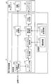
- FIG. 2 is a block diagram illustrating the configuration of the display control apparatus according to the first embodiment.
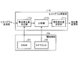
- FIG. 3 is a block diagram illustrating the configuration of the histogram analysis unit according to the first embodiment.
- FIG. 4 is a diagram illustrating an operation example of the histogram analysis unit according to the first embodiment.
- FIG. 5 is a diagram illustrating an example of RGB conversion information.
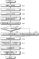
- FIG. 6 is a flowchart illustrating a processing procedure executed by the display control apparatus according to the first embodiment.
- FIG. 7 is a diagram illustrating an outline of the halation avoidance technique according to the second embodiment.
- FIG. 8 is a block diagram illustrating the configuration of the histogram analysis unit according to the second embodiment.
- FIG. 1 is a diagram illustrating an overview of a display control method according to the first embodiment.
- FIG. 2 is a block diagram illustrating the configuration of the display control apparatus according to the first embodiment.
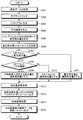
- FIG. 9 is a flowchart illustrating a processing procedure executed by the display control apparatus according to the second embodiment.
- FIG. 10 is a diagram for explaining a halation avoidance function and an H offset setting change.
- FIG. 11 is a diagram for explaining a case where the L offset is set.
- FIG. 12 is a diagram illustrating an overview of the display control method according to the third embodiment.
- FIG. 13 is a block diagram illustrating the configuration of the display control apparatus according to the third embodiment.
- FIG. 14 is a diagram illustrating an operation example of the histogram analysis unit.
- FIG. 15 is a block diagram illustrating the configuration of the light emission amount changing unit according to the third embodiment.
- FIG. 16 is a diagram illustrating an example of the change amount setting information.
- FIG. 10 is a diagram for explaining a halation avoidance function and an H offset setting change.
- FIG. 11 is a diagram for explaining a case where the L offset is set.
- FIG. 12 is a diagram illustrating an overview of the
- FIG. 17 is a diagram illustrating an operation example of the change amount determination unit and the light emission amount determination unit.
- FIG. 18 is a flowchart illustrating a processing procedure executed by the display control apparatus according to the third embodiment.
- FIG. 19 is a diagram illustrating another operation example of the change amount determination unit.
- FIG. 20 is a diagram illustrating another operation example of the change amount determination unit.
- FIG. 21 is a diagram illustrating an overview of the display control method according to the fourth embodiment.
- FIG. 22 is a block diagram illustrating a configuration of the histogram analysis unit.
- FIG. 23 is a diagram illustrating an operation example of the light emission amount determination unit when a high-luminance pixel is included in an overall dark image.
- FIG. 24 is a diagram illustrating another operation example of the light emission amount determination unit.
- FIG. 24 is a diagram illustrating another operation example of the light emission amount determination unit.
- FIG. 25 is a flowchart illustrating a processing procedure executed by the display control apparatus according to the fourth embodiment.
- FIG. 26 is a diagram for describing a case where AVEDIS is changed according to the value of partial average luminance.
- FIG. 27 is a diagram illustrating another operation example of the cumulative addition unit.
- FIG. 28 is a diagram illustrating another operation example of the light emission amount determination unit.
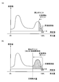
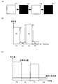
- FIG. 1 is a diagram illustrating an overview of a display control method according to the first embodiment. Note that (A) in the figure shows a case where a light emission amount lower than the provisionally determined light emission amount is determined as a definite light emission amount when a bright image is input. Further, (B) of FIG. 5 shows a case where the light emission amount tentatively determined is determined as a definite light emission amount when a dark image is input.
- the display control method when the amount of light emitted from the backlight is controlled according to the brightness of the image, the amount of light emitted from the backlight is fixed even when a bright image is input.
- the main feature is that an upper limit is set for the amount of light emitted from the backlight so as not to exceed the fixed amount.
- the display control method according to the first embodiment first, when image data is input, the pixels constituting the image data are counted in descending order of luminance value. That is, the display control method according to the first embodiment generates a luminance distribution (hereinafter, referred to as “histogram”) of the pixels constituting the image data as shown in FIG. The pixels are counted in order.
- a luminance distribution hereinafter, referred to as “histogram”.
- the luminance value of the pixel takes a value from 0 to 255, and the light emission amount of the backlight is 0% when the luminance value is 0, and 255 The value of 0 to 100% is taken as 100%.
- the light emission amount of the backlight is associated with the luminance value in advance.
- the backlight is temporarily set based on the luminance value when the accumulated number of counted pixels (hereinafter referred to as “accumulated pixel number”) reaches a predetermined number.
- accumulated pixel number the accumulated number of counted pixels
- Determine the amount of luminescence Specifically, as shown in (A) of the figure, a position where the cumulative number of pixels exceeds a predetermined number on the histogram is set as a calculation point, and a light emission amount corresponding to the calculation point is set as a temporary light emission of the backlight. It is determined as an amount (hereinafter referred to as “provisional luminescence amount”).
- the provisional light emission amount is compared with a predetermined threshold (hereinafter referred to as “H offset”).
- H offset a predetermined threshold
- the light emission amount smaller than the provisional light emission amount is determined as a definite light emission amount (hereinafter referred to as “determined light emission amount”). Determine as.
- the display control method determines the H offset as the final light emission amount.
- the light emission amount of the backlight is set to be relatively large, but the H offset located on the lower luminance side than the calculation point is set as the final light emission amount.
- the light emission amount of the backlight can be reduced as compared with the case where the light emission amount corresponding to the calculation point is set as the fixed light emission amount. Therefore, it is possible to increase the power consumption reduction amount as compared with the case where the light emission amount at the calculation point is set as the fixed light emission amount.
- the display control method according to the first embodiment by introducing the H offset as the upper limit value of the light emission amount of the backlight, even when a bright image is input, the determined light emission amount is equal to or higher than the H offset. It was decided to restrict so that it would not. Therefore, according to the display control method according to the first embodiment, it is possible to suppress a reduction in the amount of reduction in the power consumption of the backlight when a bright image is input.
- the provisional emission amount is determined as the definite emission amount of the backlight. For example, as shown in FIG. 5B, when a dark image is input, the number of pixels positioned on the low luminance side of the histogram increases, and as a result, the calculation point is positioned on the low luminance side of the H offset. Will be. In such a case, since the provisional light emission amount is smaller than the H offset, the provisional light emission amount is determined as the determined light emission amount.
- halation a phenomenon that the color of a particularly bright part in the image appears to be crushed. This may cause image quality degradation. Therefore, when there is a possibility that halation will occur, a process of avoiding the occurrence of halation by determining a light emission amount larger than the H offset as the determined light emission amount may be performed. The specific contents of the halation avoidance will be described in the second embodiment.
- the provisional light emission amount is larger than the H offset and the H offset is set as the fixed light emission amount has been described so far, but the present invention is not limited to this.
- a value obtained by converting the provisional emission amount by a predetermined conversion formula may be determined as the determined emission amount. This point will also be described later.
- the present invention is applied to a display control device that performs display control of a liquid crystal display mounted on an in-vehicle device.
- the display control device according to the present invention is not limited to this, and various types of display units that perform display using a backlight, such as a mobile terminal device, a PC (Personal Computer), or a TV (Television). It can be applied to other devices.
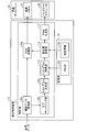
- FIG. 2 is a block diagram illustrating the configuration of the display control apparatus according to the first embodiment. In the figure, only components necessary for explaining the characteristics of the display control device are shown, and descriptions of general components are omitted.
- the display control device 10 is a device that performs display control of the liquid crystal display 20 mounted on the in-vehicle device.
- the liquid crystal display 20 includes a liquid crystal panel 21 and a backlight module 22.
- the liquid crystal panel 21 is a display unit that displays image data output from the display control device 10.
- the backlight module 22 is a lighting device provided on the back side of the liquid crystal panel 21 and irradiates the liquid crystal panel 21 with light from the back side. The high power consumption by the backlight module 22 hinders power saving.
- the display control apparatus 10 includes a control unit 11 and a storage unit 12.
- the control unit 11 includes an image data acquisition unit 11a, a sub-sampling unit 11b, a histogram generation unit 11c, a histogram analysis unit 11d, a light emission amount change unit 11e, a PWM (Pulse Width Modulation) generation unit 11f, RGB conversion unit 11g.
- the storage unit 12 stores threshold information 12a and RGB conversion information 125.
- the control unit 11 is a processing unit that executes processing such as acquisition of image data from the in-vehicle device, sub-sampling of the acquired image data, generation and analysis of a histogram, light emission amount change processing, PWM generation, or RGB conversion processing.
- the image data acquisition unit 11a is a processing unit that acquires image data such as navigation images from the in-vehicle device.
- the image data acquisition unit 11a also performs a process of passing the acquired image data to the sub-sampling unit 11b and the RGB conversion unit 11g.
- the sub-sampling unit 11b is a processing unit that performs sub-sampling on the acquired image data when the image data is acquired from the image data acquisition unit 11a. Further, the sub-sampling unit 11b also performs a process of passing the image data after sub-sampling to the histogram generation unit 11c.
- sub-sampling indicates a process of thinning out pixels from acquired image data.
- the processing speed of processing units such as a histogram generation unit 11c and a histogram analysis unit 11d described later can be increased.
- the image data of WVGA size 800 ⁇ 480
- the image data of WVGA size is reduced to a size of 128 ⁇ 64.
- the histogram generation unit 11c is a processing unit that generates a histogram using the image data after sub-sampling acquired from the sub-sampling unit 11b.
- the histogram is information representing the luminance distribution of the pixels constituting the image data.
- the histogram generation unit 11c generates a histogram using the component having the largest value among the R, G, and B components included in the image data.
- the histogram generation unit 11c also performs a process of passing the generated histogram to the histogram analysis unit 11d.
- the histogram analysis unit 11d is a processing unit that determines the determined light emission amount of the backlight module 22 by analyzing the histogram generated by the histogram generation unit 11c using the threshold information 12a.
- FIG. 3 is a block diagram illustrating the configuration of the histogram analysis unit 11d according to the first embodiment.
- the histogram analysis unit 11d includes a provisional light emission amount determination unit 111a, a comparison unit 111b, and a fixed light emission amount determination unit 111c.
- the threshold information 12a includes a DNUM 121 and an H offset 122.
- the provisional emission amount determination unit 111a is a processing unit that determines the provisional emission amount using the histogram acquired from the histogram generation unit 11c and the DNUM 121 included in the threshold information 12a.
- the DNUM 121 is information indicating a threshold value for the cumulative number of pixels.
- the provisional light emission amount determination unit 111a sequentially counts the number of pixels from the high luminance side of the histogram, and the light emission corresponding to the position (luminance value) on the histogram when the cumulative pixel number exceeds DNUM 121. The amount is determined as the provisional light emission amount. In addition, when the provisional light emission amount determination unit 111a determines the provisional light emission amount, the provisional light emission amount determination unit 111a also performs a process of passing the determined provisional light emission amount to the comparison unit 111b.
- the comparison unit 111b is a processing unit that compares the provisional emission amount determined by the provisional emission amount determination unit 111a with the H offset 122 stored in the storage unit 12.
- the H offset 122 is threshold information indicating the upper limit value of the light emission amount of the backlight module 22.
- the comparison unit 111b also performs a process of passing the comparison result between the provisional light emission amount and the H offset to the fixed light emission amount determination unit 111c.
- the determined light emission amount determination unit 111c is a processing unit that determines the determined light emission amount according to the comparison result by the comparison unit 111b.
- the determined light emission amount determining unit 111c also performs a process of passing the determined determined light emission amount to the light emission amount changing unit 11e.
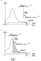
- FIG. 4 is a diagram illustrating an operation example of the histogram analysis unit 11d according to the first embodiment. Note that (A) in the figure shows an operation example of the provisional light emission amount determination unit 111a, and (B) and (C) in the same figure show operation examples of the comparison unit 111b and the fixed light emission amount determination unit 111c. Each is shown.
- the provisional light emission amount determination unit 111a sets the position of the luminance value “255” in the histogram as the counting start point.
- the provisional light emission amount determination unit 111a sequentially counts the number of pixels corresponding to each luminance value from the counting start point toward the low luminance side. Then, the provisional light emission amount determination unit 111a determines the position where the cumulative number of pixels reaches DNUM 121 as a calculation point, and determines the light emission amount corresponding to the luminance value of the calculation point as the provisional light emission amount.
- the provisional light emission amount determination unit 111a sets the light emission amount “78%” corresponding to the luminance value “200” to provisional light emission. Determine as quantity.
- the comparison unit 111b compares the provisional light emission amount determined by the provisional light emission amount determination unit 111a with the H offset 122, and passes the comparison result to the fixed light emission amount determination unit 111c. Then, as shown in (B) of the figure, when the provisional emission amount is equal to or less than the H offset, the determined emission amount determination unit 111c determines the provisional emission amount as the fixed emission amount. On the other hand, when the provisional light emission amount exceeds the H offset, the determined light emission amount determination unit 111c determines the H offset as the determined light emission amount.
- the calculation point when the calculation point is located on the lower luminance side than the H offset, such as the calculation point a and the calculation point b, that is, the input image is a dark image.
- the light emission amount (provisional light emission amount) corresponding to each calculation point is the determined light emission amount.
- the calculated points are located on the higher luminance side than the H offset as in the calculation points c to e, that is, when the input image is a bright image, the determined light emission amount corresponds to each calculated point.
- the H offset is a light emission amount smaller than the light emission amount (provisional light emission amount).
- the H offset that is a light emission amount smaller than the provisional light emission amount is set as the definite light emission amount, thereby inputting a bright image. Even if it exists, the reduction amount of the power consumption of the backlight module 22 can be increased as much as possible.
- the light emission amount changing unit 11e emits light based on the difference between the determined light emission amount acquired from the histogram analysis unit 11d and the current light emission amount in order to prevent screen flickering caused by a sudden change in the light emission amount of the backlight module 22. It is a processing unit for performing a light emission amount changing process for limiting the amount of change in the amount.
- the light emission amount changing unit 11e sets a predetermined value as the upper limit value of the change amount to the current light emission amount. A value obtained by addition (or subtraction) is determined as a final light emission amount. Further, when the light emission amount changing unit 11e determines the final light emission amount (hereinafter referred to as “changed light emission amount”), it passes this changed light emission amount to the PWM generation unit 11f.
- the light emission amount changing unit 11e will be described more specifically in the third embodiment.
- the light emission amount changing unit 11e also determines an RGB conversion coefficient corresponding to the changed light emission amount using the RGB conversion information 125, and passes the determined RGB conversion coefficient to the RGB conversion unit 11g. Do.
- the contents of the RGB conversion information 125 will be described with reference to FIG.
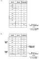
- FIG. 5 is a diagram illustrating an example of the RGB conversion information 125.
- the RGB conversion information 125 is information in which “RGB conversion coefficient” is associated with each “changed light emission amount”.
- “changed emission amount” indicates the changed emission amount determined by the emission amount changing unit 11e.
- the “RGB conversion coefficient” is a coefficient to be multiplied with the values (RGB values) of R, G, and B components.
- the RGB conversion coefficient is “1.00”. This indicates that the RGB value of the input data becomes the RGB value of the output data as it is.
- the RGB conversion coefficient is “1.26”. This indicates that a value obtained by multiplying the RGB value of the input data by 1.26 becomes the RGB value of the output data.
- R, G, and B components are respectively multiplied by RGB conversion coefficients.
- the RGB conversion information 125 is set so that the RGB conversion coefficient increases as the light emission amount after change decreases, that is, as the light emission amount of the backlight module 22 decreases and the screen becomes darker.
- the light emission amount changing unit 11e determines the light emission amount after change
- the light emission amount changing unit 11e extracts the RGB conversion coefficient associated with the determined light emission amount after change from the RGB conversion information 125, and passes the extracted RGB conversion coefficient to the RGB conversion unit 11g.
- the PWM generation unit 11f When the changed light emission amount is acquired from the light emission amount changing unit 11e, the PWM generation unit 11f generates a PWM signal whose pulse width is adjusted so that the light emission amount of the backlight module 22 becomes the changed light emission amount, and the backlight module 22 It is a processing part which outputs to. Note that the PWM generator 11f outputs the PWM signal four times by default every time VSYNC (Vertical Synchronizing signal) is output once. However, the number of output of the PWM signal per unit output of VSYNC can be appropriately adjusted by a register.
- VSYNC Very Synchronizing signal
- the RGB conversion unit 11g performs an RGB conversion process of multiplying the R, G, and B component values included in the image data acquired from the image data acquisition unit 11a by the RGB conversion coefficient acquired from the light emission amount change unit 11e. Is a processing unit.
- the RGB converter 11g also performs a process of outputting the image data after the RGB conversion process to the liquid crystal panel 21.
- the RGB conversion unit 11g when the RGB conversion unit 11g acquires the RGB conversion coefficient “1.26”, the RGB conversion unit 11g multiplies the values of the R, G, and B components included in the image data acquired from the image data acquisition unit 11a by 1.26. .
- the RGB converter 11g outputs image data obtained by multiplying the values of the R, G, and B components by 1.26 to the liquid crystal panel 21.
- FIG. 6 is a flowchart illustrating a processing procedure executed by the display control apparatus according to the first embodiment. In the figure, only the processing procedure related to the light emission amount control of the backlight among the processing procedures executed by the display control device 10 is shown.
- the display control apparatus 10 when the image data acquisition unit 11a acquires image data (step S101), the sub-sampling unit 11b performs sub-sampling on the acquired image data (step S102). ). Subsequently, in the display control device 10, the histogram generation unit 11c generates a histogram using the image data after sub-sampling (step S103), and the temporary light emission amount determination unit 111a uses the histogram and the DNUM 121 to generate a temporary light emission amount. Is determined (step S104).
- the comparison unit 111b compares the provisional light emission amount with the H offset 122 (step S105), and the determined light emission amount determination unit 111c determines whether or not the provisional light emission amount is larger than the H offset 122. Is determined (step S106). Then, when the provisional emission amount is larger than the H offset (Yes in step S106), the determined emission amount determination unit 111c sets the H offset as the decision emission amount (step S107), and the provisional emission amount is equal to or less than the H offset. In this case (No at Step S106), the provisional light emission amount is set as the fixed light emission amount (Step S108).
- the light emission amount changing unit 11e performs a light emission amount changing process to determine the changed light emission amount (step S109).
- the PWM generator 11f generates a PWM signal corresponding to the changed light emission amount and outputs the PWM signal to the backlight module 22 (step S110).
- the RGB conversion unit 11g performs an RGB conversion process of multiplying R, G, and B component values included in the image data acquired from the image data acquisition unit 11a by an RGB conversion coefficient corresponding to the changed light emission amount. Is performed (step S111). Then, the RGB conversion unit 11g outputs the image data after the RGB conversion processing to the liquid crystal panel 21 (step S112), and ends the processing.
- the provisional light emission amount determination unit counts pixels constituting the image data in descending order of luminance value for the input image data, and accumulates the counted pixels.
- the provisional light emission amount of the backlight is determined based on the luminance value when the number reaches the predetermined number, the comparison unit compares the temporary light emission amount with a predetermined threshold value, and the determined light emission amount determination unit As a result of comparison by the comparison unit, when the provisional light emission amount exceeds a predetermined threshold, the light emission amount smaller than the provisional light emission amount is determined as the definite light emission amount of the backlight. Accordingly, it is possible to suppress a reduction in the amount of reduction in power consumption of the backlight when a bright image is input.
- the image quality deterioration is prevented by performing the correction for increasing the RGB value by the RGB conversion processing.
- Example 2 it is determined whether there is a possibility that halation will occur when the provisional light emission amount is larger than the H offset, and when it is determined that there is a possibility that it will occur, it is larger than the H offset. By determining the light emission amount as the definite light emission amount, the occurrence of halation was avoided.
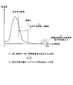
- FIG. 7 is a diagram illustrating an outline of the halation avoidance technique according to the second embodiment.
- (A) of the figure shows the situation where halation occurs
- (B) of the figure shows an outline of the halation avoidance technique.
- the RGB conversion coefficient is “1.00” (see FIG. 5). That is, when the input RGB value is “255”, the output RGB value is also “255”.
- the RGB conversion coefficient is “2.05” (see FIG. 5).
- the output RGB values are all “255” (that is, the output RGB value is “255”).
- the output RGB value should be “410”.
- the limit value of the RGB value is “255”
- the output RGB value is “255”. It becomes.
- the image data includes a pixel having a large RGB value
- the converted RGB value output RGB value
- portions that should originally be expressed with different RGB values are all expressed with the same RGB value (255) by the RGB conversion processing. May deteriorate.
- the display control apparatus 10 determines whether or not there is a possibility of halation when a bright image is input, that is, when the provisional light emission amount is larger than the H offset, When it is determined that there is a risk of occurrence, the light emission amount larger than the H offset is determined as the determined light emission amount.
- the display control apparatus 10 calculates the average luminance of the image data after sub-sampling as shown in (B) of the figure, and the average luminance corresponds to the H offset. If it is higher than that, it is determined that halation may occur.
- the display control device 10 determines that there is a high possibility that halation will occur, the display control device 10 does not set the H offset as the fixed light emission amount, but sets the light emission amount corresponding to the average luminance as the fixed light emission. Amount.
- the RGB conversion coefficient may be reduced and the output RGB value may reach a peak by setting the determined light emission amount to be higher than the H offset. Since it is suppressed, the occurrence of halation can be avoided.
- the histogram analysis unit 11d 'according to the second embodiment further includes an average luminance calculation unit 111d in addition to the configuration of the histogram analysis unit 11d described in the first embodiment.
- the average luminance calculation unit 111d is a processing unit that acquires a histogram from the histogram generation unit 11c and calculates the average luminance of the subsampled image data using the acquired histogram.
- the average luminance calculation unit 111d also performs a process of passing the calculated average luminance to the comparison unit 111b.
- the comparison unit 111b further compares the average luminance acquired from the average luminance calculation unit 111d with the luminance value corresponding to the H offset. In addition, the comparison unit 111b also performs a process of passing this comparison result to the determined light emission amount determination unit 111c.
- the determined light emission amount determination unit 111c determines whether or not the average luminance is higher than the luminance value corresponding to the H offset. Then, when it is determined that the average luminance is higher than the luminance value corresponding to the H offset, the determined light emission amount determination unit 111c determines the light emission amount corresponding to the average luminance as the determined light emission amount.
- FIG. 9 is a flowchart illustrating a processing procedure executed by the display control apparatus according to the second embodiment. In the figure, only the processing procedure related to the light emission amount control of the backlight among the processing procedures executed by the display control device 10 is shown.
- the sub-sampling unit 11b performs sub-sampling on the acquired image data (step S202). ).
- the histogram generation unit 11c generates a histogram using the image data after sub-sampling (step S203), and the average luminance calculation unit 111d uses the histogram to output the image data after sub-sampling. Is calculated (step S204).
- the provisional light emission amount determining unit 111a determines the provisional light emission amount using the histogram and the DNUM 121 (step S205).
- the comparison unit 111b compares the provisional light emission amount with the H offset 122 (step S206), and the determined light emission determination unit 111c determines whether or not the provisional light emission amount is larger than the H offset 122. Is determined (step S207). Subsequently, when the provisional light emission amount is larger than the H offset (step S207, Yes), the determined light emission amount determination unit 111c further determines whether or not the average luminance is higher than the luminance value corresponding to the H offset. (Step S208).
- the determined emission amount determining unit 111c determines the emission amount corresponding to the average luminance as the determined emission amount. (Step S209).
- the determined light emission amount determining unit 111c determines the H offset as the determined light emission amount (Step S210). In step S207, if the provisional light emission amount is not greater than the H offset (No in step S207), the provisional light emission amount is determined as the determined light emission amount (step S211).
- the light emission amount changing unit 11e performs a light emission amount changing process based on the difference between the determined light emission amount acquired from the determined light emission amount determining unit 111c and the current light emission amount, and determines the changed light emission amount (step S212).
- the PWM generation unit 11f generates a PWM signal corresponding to the changed light emission amount and outputs the PWM signal to the backlight module 22 (step S213).
- the RGB conversion unit 11g performs an RGB conversion process of multiplying R, G, and B component values included in the image data acquired from the image data acquisition unit 11a by an RGB conversion coefficient corresponding to the changed light emission amount. Is performed (step S214). Then, the RGB conversion unit 11g outputs the image data after the RGB conversion processing to the liquid crystal panel 21 (step S215), and ends the processing.
- the average luminance calculation unit calculates the average luminance of the image data
- the comparison unit further compares the average luminance calculated by the average luminance calculation unit with the H offset and confirms it. If the provisional light emission amount exceeds the H offset and the average luminance exceeds the H offset as a result of the comparison by the comparison unit, the light emission amount determination unit determines the average luminance as the definite light emission amount of the backlight. It was.
- the second embodiment when a bright image is input, it is possible to prevent image quality deterioration due to the occurrence of halation while suppressing a reduction in power consumption of the backlight module 22 from being reduced.
- FIG. 10 is a diagram for explaining a halation avoidance function and an H offset setting change.
- image quality emphasis mode the state where the halation avoidance function is ON
- power saving mode the case where it is OFF
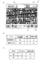
- the liquid crystal panel 21 displays a mode selection button 21a, a “dark” button 21c and a “bright” button 21d for adjusting the screen brightness.
- the liquid crystal panel 21 displays the current power consumption reduction rate 21b.
- “image quality emphasis mode” is selected, and “brightness” is set to 4 out of 7 levels.
- “30%” is displayed as the current power consumption reduction rate.
- the user can select either the image quality emphasis mode or the power saving mode according to his / her preference by pressing the mode selection button 21a while confirming the image displayed on the liquid crystal panel 21. .
- the image quality emphasis mode in the image quality emphasis mode, the image quality is improved because halation is prevented, and the light emission amount less than the provisional light emission amount is emitted from the backlight module 22. Since it is used as a quantity, it has a high power saving effect. On the other hand, in the power saving mode, there is a possibility that halation may occur. Therefore, although the image quality is inferior to that in the image quality emphasis mode, the light emission amount of the backlight module 22 is further reduced. Compared to higher.
- a user who thinks that the image quality is high enough to recognize characters can improve the power saving effect by selecting the power saving mode.
- the user can confirm the image quality of the image displayed on the liquid crystal panel 21 and the power consumption reduction rate 21b, and press the “dark” button 21c and the “bright” button 21d, so that the brightness according to the user's preference can be obtained. Can be adjusted.
- the value of the H offset is set so as to decrease as the “dark” button 21c is pressed and increase as the “bright” button 21d is pressed. Has been.
- the “dark” button 21c is pressed to reduce the value of the H offset, the upper limit value of the light emission amount of the backlight module 22 is lowered, and the power saving effect is further enhanced.
- the value of the H offset may be extremely lowered to greatly increase the power saving effect.
- a line-of-sight detection sensor is provided on the liquid crystal display 20.
- the gaze detection sensor is a sensor that detects the gaze direction of the user, and outputs the detection result to the display control device 10.
- control unit 11 of the display control apparatus 10 determines whether or not the user's line of sight is on the liquid crystal panel 21, and detects the viewer of the image when determining that the user's line of sight is on the liquid crystal panel 21. And the control part 11 of the display control apparatus 10 reduces the value of H offset significantly, when the viewer of an image is not detected.
- control unit 11 of the display control apparatus 10 functions as a viewer detection unit to detect a viewer of an image displayed on the liquid crystal panel 21. Further, the control unit 11 of the display control device 10 functions as a threshold value changing unit, so that when the image viewer is not detected, the value of the H offset is compared with the case where the image viewer is detected. Lower.
- the upper limit value of the light emission amount of the backlight module 22 is greatly reduced, so that a power saving effect is achieved. It can be further increased.
- the definite amount of light emission is 0% regardless of what image data is input.
- the power consumption of the module 22 can be reduced to the maximum.
- the present invention is not limited to this.
- a value obtained by converting the provisional emission amount by a predetermined conversion formula may be determined as the determined emission amount.
- the determined emission amount determination unit 111c obtains a value obtained by converting the provisional emission amount using the above conversion formula. Is determined as the definite light emission amount.
- the deterministic light emission amount determination unit 111c uses, for example, a linear function that obtains a definite light emission amount smaller than the provisional light emission amount by multiplying the provisional light emission amount by a coefficient larger than 0 and smaller than 1 as a conversion equation. be able to.
- the determined light emission amount becomes smaller than the provisional light emission amount, and the fixed light emission amount changes depending on the provisional light emission amount, so that the reduction in the amount of power consumption of the backlight is reduced.
- the backlight can be emitted with a fixed light emission amount suitable for each image.
- the conversion expression may be any conversion expression as long as the value before conversion is smaller than the value after conversion.
- FIG. 11 is a diagram for explaining a case where the L offset is set.
- the provisional light emission amount determination unit 111a sequentially counts the number of pixels from the high luminance side of the histogram, and corresponds to the position (luminance value) on the histogram when the cumulative number of pixels exceeds DNUM 121. The amount of light emitted is determined as the provisional light emission amount. Subsequently, the comparison unit 111b compares the provisional light emission amount with another threshold value (L offset) set on the lower luminance side than the H offset.
- L offset another threshold value
- the determined emission amount determination unit 111c determines the provisional emission amount as it is as the fixed emission amount.
- the determined light emission amount determining unit 111c determines the L offset as the determined light emission amount.
- Patent Document 1 has a problem that flicker may occur on the screen displayed on the liquid crystal display when the brightness of the image changes frequently. This is because a dark portion of an image is easily affected by luminance due to a change in the amount of backlight emission, and a sudden change in the amount of backlight emission causes flickering.
- the backlight emission amount is set to be large even though the scene is dark, or conversely, even though the scene is bright.
- the amount of light emitted from the backlight may be set to be small, which causes flickering on the screen.
- Example 3 when the target light emission amount of the backlight is determined based on the luminance distribution of the input image, the determined light emission amount is obtained by changing the current light emission amount step by step over a plurality of frames. To match.
- Example 3 will be described with reference to FIGS.
- the same reference numerals as those in the first or second embodiment are used for the same functions as those of the display control apparatus 10 according to the first or second embodiment, and the description thereof is omitted. To do.
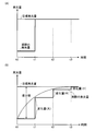
- FIG. 12 is a diagram illustrating an overview of the display control method according to the third embodiment.
- (A) in the figure shows an outline of a conventional display control technique
- (B) in the figure shows an outline of a display control technique according to the third embodiment.
- the graph shown to (A) and (B) of the figure represents the time-dependent change of the emitted light quantity of a backlight. Times t0 to t3 attached to the horizontal axis represent frame update timings.
- the target light emission amount is determined based on the luminance distribution of a certain frame
- the determined target light emission amount is directly adopted as the light emission amount of the backlight in the next frame.
- the target light emission amount determined based on the luminance distribution of the frame updated at time t0 is used as the light emission amount of the backlight at time t1.
- the target light emission amount determined based on the luminance distribution of the frame updated at time t0 is used as the light emission amount of the backlight at time t1.
- the target light emission amount when the target light emission amount is immediately reflected as the backlight light emission amount, when the actual light emission amount and the target light emission amount are greatly different, the backlight light emission amount changes abruptly. There is a risk of flickering. In particular, when a bright image and a dark image are alternately repeated, the difference between the light emission amount to be applied and the light emission amount actually applied tends to increase, and the flickering of the screen becomes remarkable.
- the current light emission amount is changed stepwise over a plurality of frames. It is characterized in that it matches the determined light emission amount.
- the current light emission amount is not changed linearly, but is increased as the difference from the target light emission amount is increased, and the change amount is reduced as the target light emission amount is approached. It also has a feature in that it can be changed.
- the amount of change from the current light emission amount is Determine the amount of change (large).
- the light emission amount obtained by changing the current light emission amount by the change amount (large) is applied to the frame updated at t1.
- the amount of change (large) is an amount of change that does not cause screen flickering.
- the difference value between the light emission amount (current light emission amount) and the target light emission amount at time t1 is smaller than the difference value between the light emission amount (current light emission amount) and the target light emission amount at time t0. For this reason, in the display control method according to the third embodiment, a change amount (medium) is determined as a change amount from the current light emission amount. In the display control method according to the third embodiment, the light emission amount obtained by changing the current light emission amount by the change amount (medium) is applied to the frame updated at t2.
- the difference value between the light emission amount (current light emission amount) and the target light emission amount at time t2 is smaller than the difference value between the light emission amount (current light emission amount) and the target light emission amount at time t1.
- the change amount (small) is determined as the change amount from the current light emission amount.
- the light emission amount obtained by changing the current light emission amount by the change amount (small) is applied to the frame updated at t3.
- the actual light emission amount of the backlight coincides with the target light emission amount determined based on the luminance distribution of the frame updated at time t0 at time t3.
- the change is made stepwise over a plurality of frames. As a result, flickering of the screen can be prevented.
- the current light emission amount is greatly changed with a change amount that does not cause flickering of the screen.
- the difference value decreases, the amount of change is also reduced, so that the current light emission amount is smoothly converged to the target light emission amount.
- the light emission amount of the backlight can be brought close to the target light emission amount as quickly as possible, so that the color collapse that tends to occur when the difference between the light emission amount of the backlight and the target light emission amount is large can be prevented.
- the screen may flicker. Therefore, if the difference value between the target light emission amount and the current light emission amount is a predetermined value or less, the light emission amount of the backlight may not be changed. Accordingly, it is possible to prevent screen flickering caused by a slight change in the light emission amount of the backlight.
- the amount of change from the current light emission amount may be reduced. As a result, it is possible to reduce the processing load caused by frequently changing the light emission amount of the backlight in a short period.
- 12A and 12B illustrate the case where the light emission amount of the backlight is increased toward the target light emission amount, but in the display control method according to the third embodiment, the light emission amount of the backlight is the target. Similarly, in the case of decreasing toward the light emission amount, the light emission amount of the backlight is changed stepwise.
- the light emission amount of the backlight when the light emission amount of the backlight is decreased, the amount of change may be larger than when the light emission amount of the backlight is increased. Thereby, when reducing the light emission amount of the backlight, the light emission amount of the backlight module 22 can be brought closer to the target light emission amount without causing the viewer to feel the flickering of the screen.
- FIGS. 12A and 12B the case where the actual light emission amount of the backlight is changed in three stages has been described.
- the present invention is not limited to this. There is no problem.
- the display control apparatus includes a display unit that performs display using a backlight, such as a mobile terminal device, a PC (Personal Computer), or a TV (Television).
- a display unit that performs display using a backlight, such as a mobile terminal device, a PC (Personal Computer), or a TV (Television).
- the present invention can be applied to various devices.
- FIG. 13 is a block diagram illustrating the configuration of the display control apparatus according to the third embodiment.
- the display control apparatus 10 according to the third embodiment includes a storage unit 12 ′ instead of the storage unit 12 in the display control apparatus 10 according to the first embodiment.
- the storage unit 12 ' stores a DNUM 121 and setting information 12b. The specific contents of the setting information 12b will be described later.
- the histogram analysis unit 11d is a processing unit that determines the definite light emission amount of the backlight module 22 by analyzing the histogram generated by the histogram generation unit 11c using the DNUM 121.
- the DNUM 121 is information indicating a threshold value for the cumulative number of pixels as described above.
- FIG. 14 is a diagram illustrating an operation example of the histogram analysis unit 11d.
- (A) in the figure shows an operation example of the cumulative pixel counting process using the histogram
- (B) in the figure shows an operation example of the target light emission amount determination process. .
- the luminance value of the pixel takes a value from 0 to 255.
- the light emission amount of the backlight is associated with the luminance value in advance so as to take a value of 0 to 100%, with 0% when the luminance value is 0 and 100% when the luminance value is 255.
- the histogram analysis unit 11d acquires the histogram from the histogram generation unit 11c, first, the histogram analysis unit 11d performs a counting process of counting the number of pixels in order from the high luminance side of the histogram. Specifically, as illustrated in (A) of FIG. 11, the histogram analysis unit 11 d uses the position of the luminance value “255” in the histogram as the counting start point, and sets the number of pixels corresponding to each luminance value as the counting start point. Counts in order from the low brightness side.
- the position corresponding to the luminance value being analyzed is referred to as “calculation point”.
- the histogram analysis unit 11 d calculates a calculation point (luminance value) when the accumulated number of counted pixels (hereinafter referred to as “accumulated pixel number”) reaches DNUM 121. ) Is determined as the target light emission amount.
- the histogram analysis unit 11d sets the light emission amount “78%” corresponding to the luminance value “200” as the target light emission amount. decide.
- the histogram generation unit 11c and the histogram analysis unit 11d function as an example of target light emission amount determining means for determining the target light emission amount of the backlight based on the luminance distribution of the input image data.
- the display control apparatus 10 according to the third embodiment includes the histogram analysis unit 11d according to the first embodiment
- the present invention is not limited thereto, and the histogram control unit 11d ′ according to the second embodiment is provided. It is good as well.
- the light emission amount changing unit 11e is a processing unit that determines the light emission amount of the backlight module 22 based on the difference between the target light emission amount acquired from the histogram analysis unit 11d and the current light emission amount.
- the configuration of the light emission amount changing unit 11e will be described with reference to FIG.
- FIG. 15 is a block diagram illustrating a configuration of the light emission amount changing unit 11e according to the third embodiment.
- the light emission amount change unit 11e includes a difference value calculation unit 112a, a change amount determination unit 112b, a light emission amount determination unit 112c, and a conversion coefficient determination unit 112d.
- the setting information 12b stores light emission amount history information 123, change amount setting information 124, and RGB conversion information 125.
- the light emission amount history information 123 is history information of the light emission amount of the backlight module 22 determined by the light emission amount determination unit 112c.
- the light emission amount history information 123 includes the current light emission amount of the backlight module 22 as history information.
- the change amount setting information 124 is information used when determining the change amount of the light emission amount of the backlight module 22.
- the light emission amount history information 123 will be described later with reference to FIG.
- the RGB conversion information 125 is information in which “RGB conversion coefficient” is associated with each light emission amount of the backlight module 22 determined by the light emission amount determination unit 112c.
- the “RGB conversion coefficient” is a coefficient that is multiplied with the values (RGB values) of R, G, and B components.
- the RGB conversion information 125 is set so that the RGB conversion coefficient increases as the light emission amount of the backlight module 22 determined by the light emission amount determination unit 112c decreases, that is, as the screen becomes darker.
- the difference value calculation unit 112a is a processing unit that calculates a difference value between the target light emission amount acquired from the histogram analysis unit 11d and the current light emission amount. Specifically, when obtaining the target light emission amount from the histogram analysis unit 11d, the difference value calculation unit 112a extracts the current light emission amount included in the light emission amount history information 123 and subtracts the current light emission amount from the target light emission amount. The absolute value is the difference value.
- the difference value calculation unit 112a is information indicating whether the value obtained by subtracting the current light emission amount from the target light emission amount is a positive value or a negative value, that is, the current light emission amount should be increased or decreased. A process of passing information indicating whether or not to be performed to the change amount determination unit 112b together with the calculated difference value is also performed.
- the change amount determination unit 112b is a processing unit that determines a change amount from the current light emission amount according to the difference value acquired from the difference value calculation unit 112a. Specifically, the change amount determination unit 112b uses the change amount setting information 124 for the change amount associated with the range to which the difference value acquired from the difference value calculation unit 112a belongs among the ranges divided by a plurality of threshold values. The determined change amount is determined as a change amount from the current light emission amount.
- FIG. 16 is a diagram illustrating an example of the change amount setting information 124.
- the change amount setting information 124 is information in which a change amount is associated with each range divided by a plurality of threshold values (threshold value L1 and threshold value L2) having different sizes. Specifically, the change amount setting information 124 is information in which “change amount (increase)” and “change amount (decrease)” are associated with each “range” delimited by the threshold L1 and the threshold L2. .
- range includes ranges “A1” to “A3”. Specifically, the range “A1” indicates a range where “threshold L1 ⁇ difference value”, the range “A2” indicates a range where “threshold L2 ⁇ difference value ⁇ threshold L1”, and the range “A3” indicates “ A range where difference value ⁇ threshold value L2 ”is shown. As shown in the figure, the threshold value L1 is assumed to be larger than the threshold value L2.
- “change amount (when increased)” is information indicating a change amount applied when the light emission amount of the backlight module 22 is increased.
- “HI_1” is stored in association with the range “A1”
- “MID_1” is stored in association with the range “A2”
- “LOW_1” is stored in association with the range “A3”.
- the amount of change (at the time of increase) is “HI_1” is the largest and “LOW_1” is the smallest among “HI_1”, “MID_1”, and “LOW_1”.
- the change amount “HI — 1” is a change amount that does not cause screen flicker in the liquid crystal display 20.
- “change amount (at the time of decrease)” is information indicating the change amount used when the light emission amount of the backlight module 22 is reduced.
- “HI_2” is stored in association with the range “A1”
- “MID_2” is stored in association with the range “A2”
- “LOW_2” is stored in association with the range “A3”.
- the amount of change (at the time of decrease) is “HI_2” is the largest and “LOW_2” is the smallest among “HI_2”, “MID_2”, and “LOW_2”.
- “HI_2” of the amount of change (when decreasing) is larger than “HI_1” of the amount of change (when increasing).
- the change amount setting information 124 associates a larger change amount with a range delimited by a threshold having a larger value among ranges delimited by a plurality of threshold values.
- the change amount setting information 124 is first change amount setting information used when the target light emission amount is larger than the current light emission amount, and second change information used when the target light emission amount is smaller than the current light emission amount. Change amount setting information.
- the change amount determination unit 112b determines the change amount corresponding to the range to which the difference value acquired from the difference value calculation unit 112a belongs as the change amount of the backlight module 22 by referring to the change amount setting information 124. Further, the change amount determination unit 112b also performs a process of passing the determined change amount and information indicating whether the current light emission amount should be increased or decreased to the light emission amount determination unit 112c.
- the difference value calculation unit 112a and the change amount determination unit 112b are based on the difference value between the target light emission amount determined by the target light emission amount determination unit and the current light emission amount of the backlight. It functions as an example of a change amount determining means for determining a change amount.
- the light emission amount determination unit 112c is a processing unit that determines the light emission amount obtained by changing the current light emission amount by the change amount determined by the change amount determination unit 112b as the light emission amount of the backlight module 22. Specifically, the light emission amount determination unit 112c performs a process of taking out the current light emission amount from the light emission amount history information 123 and changing the extracted current light emission amount by the change amount acquired from the change amount determination unit 112b.
- the light emission amount determination unit 112c uses the current light emission amount extracted from the light emission amount history information 123.
- a value obtained by adding the change amounts acquired from the change amount determination unit 112b is determined as the light emission amount of the backlight module 22.
- the light emission amount determination unit 112c changes with respect to the current light emission amount extracted from the light emission amount history information 123. A value obtained by subtracting the change amount acquired from the amount determination unit 112b is determined as the light emission amount of the backlight module 22.
- the light emission amount determination unit 112c determines the light emission amount of the backlight module 22
- the light emission amount determination unit 112c passes the determined light emission amount to the PWM generation unit 11f and the conversion coefficient determination unit 112d.
- the light emission amount determination unit 112c determines the light emission amount of the backlight module 22
- the light emission amount determination unit 112c also performs a process of storing the determined light emission amount in the light emission amount history information 123.
- FIG. 17 is a diagram illustrating an operation example of the change amount determination unit 112b and the light emission amount determination unit 112c.
- 2A shows an operation example when the light emission amount of the backlight module 22 is increased
- FIG. 2B shows an operation example when the light emission amount of the backlight module 22 is decreased. Respectively.
- the target light emission amount shown in (A) of the figure is a target light emission quantity based on the histogram of the frame (image data) updated at time t0, and the target light emission quantity shown in (B) of FIG. It is assumed that the target light emission amount is based on the histogram of the frame updated at time t4.
- the difference value D1 between the light emission amount (current light emission amount) applied to the frame updated at time t0 and the target light emission amount is within the range “A1” shown in FIG. ".
- the change amount determination unit 112b extracts the change amount (in the increase) “HI_1” corresponding to the range “A1” from the change amount setting information 124, and passes the extracted change amount “HI_1” to the light emission amount determination unit 112c. .
- the light emission amount determination unit 112c acquires the change amount “HI_1” from the change amount determination unit 112b, the light emission amount determination unit 112c extracts the current light emission amount from the light emission amount history information 123, and the change amount “HI_1” with respect to the extracted current light emission amount. ] Is determined as the backlight module 22. As a result, the light emission amount of the backlight module 22 is increased by the change amount “HI_1” at the time t1.
- the change amount determining unit 112b extracts the change amount (when increasing) “MID_1” corresponding to the range “A2” from the change amount setting information 124, and passes the extracted change amount “MID_1” to the light emission amount determining unit 112c.
- the change amount “MID_1” is a value smaller than the change amount “HI_1”.
- the light emission amount determination unit 112c acquires the change amount “MID_1” from the change amount determination unit 112b, the light emission amount determination unit 112c extracts the current light emission amount from the light emission amount history information 123, and the change amount “MID_1” with respect to the extracted current light emission amount. ] Is determined as the backlight module 22. As a result, the light emission amount of the backlight module 22 is increased by the change amount “MID_1” at the time t2.
- the change amount determination unit 112b extracts the change amount (when increasing) “LOW_1” corresponding to the range “A3” from the change amount setting information 124, and passes the extracted change amount “LOW_1” to the light emission amount determination unit 112c. .
- the change amount “LOW_1” is smaller than the change amount “MID_1”.
- the light emission amount determination unit 112c acquires the change amount “LOW_1” from the change amount determination unit 112b, the light emission amount determination unit 112c extracts the current light emission amount from the light emission amount history information 123, and the change amount “LOW_1” with respect to the extracted current light emission amount. ] Is determined as the backlight module 22. As a result, the light emission amount of the backlight module 22 is increased by the change amount “LOW_1” at time t3.
- the light emission amount of the backlight module 22 when the light emission amount of the backlight module 22 is matched with the target light emission amount, the light emission amount of the backlight module 22 is not changed suddenly in one frame, but is stepped over a plurality of frames. It was decided to make it correspond with the target light emission amount by changing it periodically. Therefore, a rapid change in the light emission amount of the backlight module 22 can be suppressed, and as a result, flickering of the screen can be prevented.
- Example 3 when the difference value between the current light emission amount and the target light emission amount is large, the current light emission amount is largely changed by a change amount that does not cause flickering of the screen, while the difference value is small. As the amount of change gradually decreases, the current light emission amount is gradually converged to the target light emission amount. As a result, the light emission amount of the backlight module 22 can be brought close to the target light emission amount as soon as possible, so that color collapse that is likely to occur when the difference between the light emission amount of the backlight module 22 and the target light emission amount is large can be prevented. .
- the change amount determination unit 112b extracts the change amount (when reduced) “HI_2” corresponding to the range “A1” from the change amount setting information 124, and passes the extracted change amount “HI_2” to the light emission amount determination unit 112c. .
- the light emission amount determination unit 112c acquires the change amount “HI_2” from the change amount determination unit 112b
- the light emission amount determination unit 112b extracts the current light emission amount from the light emission amount history information 123, and the change amount “HI_2” with respect to the extracted current light emission amount.
- the value obtained by subtracting “ is determined as the backlight module 22.
- the light emission amount of the backlight module 22 is reduced by the change amount “HI_2” at time t5.
- the amount of change “HI_2” used when the backlight module 22 is decreased is larger than the amount of change “HI_1” used when the backlight module 22 is increased. Value. This is because the viewer is less likely to recognize when the screen is darkened instantaneously than when the screen is brightened instantaneously.
- the maximum light emission amount when the light emission amount of the backlight module 22 is decreased larger than the maximum light emission amount when the light emission amount of the backlight module 22 is increased the viewer feels flickering on the screen. Without this, the light emission amount of the backlight module 22 can be brought closer to the target light emission amount more quickly.
- the amount of power consumption reduction by the backlight module 22 increases, so that the power saving effect can be further enhanced.
- the difference value D5 between the light emission amount applied to the frame updated at time t5 and the target light emission amount belongs to the range “A2”
- the light emission amount of the backlight module 22 changes at time t6. It will decrease by “MID_2”.
- the difference value D6 between the light emission amount applied to the frame updated at time t6 and the target light emission amount belongs to the range “A3”
- the light emission amount of the backlight module 22 changes at time t7. It will decrease by “LOW_2”.
- the value of the change amount stored as the light emission amount history information 123 can be arbitrarily set. For example, by setting each change amount (for example, “HI — 1”, “MID — 1”, etc.) to be a little smaller as a whole, the light emission amount of the backlight module 22 gradually changes toward the target light emission amount. For this reason, it is possible to more reliably prevent the occurrence of screen flicker.
- each change amount for example, “HI — 1”, “MID — 1”, etc.
- halation refers to a phenomenon in which the color of a particularly bright portion in an image appears to be crushed by causing the backlight module 22 to emit light with a small amount of light emission when a bright image is input.
- each change amount stored as the light emission amount history information 123 is set to be a large amount as a whole, the actual light emission amount quickly follows the target light emission amount, thereby preventing the occurrence of halation. it can. However, in such a case, the amount of change in the actual light emission amount increases, and thus the screen flickers easily. Considering such circumstances, if the value of the change amount stored as the light emission amount history information 123 is set to an appropriate value according to the device characteristics of the liquid crystal display 20, the occurrence of halation and the screen It is possible to prevent the occurrence of flickering with a good balance.
- the values of the threshold value L1 and the threshold value L2 stored as the light emission amount history information 123 can be arbitrarily set.
- the set number of thresholds can be arbitrarily changed. In particular, when the number of thresholds is set to 0, the target light emission amount can be immediately reflected on the actual light emission amount.
- the conversion coefficient determination unit 112d is a processing unit that determines the RGB conversion coefficient corresponding to the acquired light emission amount using the RGB conversion information 125 when the light emission amount of the backlight module 22 is acquired from the light emission amount determination unit 112c. .
- the conversion coefficient determination unit 112d also performs a process of passing the determined RGB conversion coefficient to the RGB conversion unit 11g.
- the PWM generation unit 11f is a processing unit that generates a PWM signal whose pulse width is adjusted so that the light emission amount of the backlight module 22 becomes the light emission amount acquired from the light emission amount determination unit 112c, and outputs the PWM signal to the backlight module 22. is there. Note that the PWM generator 11f outputs the PWM signal four times by default every time VSYNC (Vertical Synchronizing signal) is output once. However, the number of output of the PWM signal per unit output of VSYNC can be appropriately adjusted by a register.
- the RGB conversion unit 11g multiplies the R, G, B component values included in the image data acquired from the image data acquisition unit 11a by the RGB conversion coefficient acquired from the conversion coefficient determination unit 112d. Is a processing unit.
- the RGB converter 11g also performs a process of outputting the image data after the RGB conversion process to the liquid crystal panel 21.
- the RGB conversion unit 11g when the RGB conversion unit 11g acquires the RGB conversion coefficient “1.26”, the RGB conversion unit 11g multiplies the values of the R, G, and B components included in the image data acquired from the image data acquisition unit 11a by 1.26. .
- the RGB converter 11g outputs image data obtained by multiplying the values of the R, G, and B components by 1.26 to the liquid crystal panel 21.
- the RGB conversion information 125 is set such that the RGB conversion coefficient increases as the light emission amount of the backlight module 22 determined by the light emission amount determination unit 112c decreases. Therefore, the RGB conversion unit 11g corrects the RGB value to be larger as the light emission amount of the backlight module 22 is smaller.
- the RGB conversion unit 11g corrects the RGB value to be larger as the light emission amount of the backlight module 22 is smaller.
- the RGB brightness is increased by the RGB conversion unit 11g, so that the apparent brightness is kept constant and the image quality is improved. Deterioration is to be prevented.
- FIG. 18 is a flowchart illustrating a processing procedure executed by the display control apparatus 10 according to the third embodiment.
- the figure shows a processing procedure of the display control apparatus 10 when the light emission amount of the backlight module 22 is increased.
- the change amount determination unit 112b of the display control apparatus 10 determines whether to increase or decrease the light emission amount of the backlight module 22 based on information from the difference value calculation unit 112a.
- the sub-sampling unit 11b performs sub-sampling on the image data acquired by the image data acquisition unit 11a (step S301).
- the histogram generation unit 11c generates a histogram using the image data after sub-sampling (step S302), and the histogram analysis unit 11d determines the target light emission amount using the histogram and DNUM 121. (Step S303).
- the difference value calculation unit 112a calculates a difference value between the target light emission amount and the current light emission amount (step S304), and the change amount determination unit 112b has the calculated difference value in the range “ It is determined whether it belongs to “A1” (step S305). If it is determined that the difference value belongs to the range “A1” (step S305, Yes), the change amount determination unit 112b selects the change amount “HI_1” with reference to the change amount setting information 124 (step S305). S306).
- the change amount determination unit 112b determines whether or not the calculated difference value belongs to the range “A2”. Determination is made (step S307).
- the change amount determination unit 112b selects the change amount “MID_1” with reference to the change amount setting information 124 (step S307). S308).
- the change amount determination unit 112b refers to the change amount setting information 124 and sets the change amount “LOW_1”. Select (step S309).
- the light emission amount determination unit 112c adds a value obtained by adding the amount of change selected in any of steps S306, 308, and 309 to the current light emission amount extracted from the light emission amount history information 123. Is determined (step S310). Further, the light emission amount determination unit 112c stores the determined light emission amount in the light emission amount history information 123 (step S311).
- the PWM generation unit 11f generates a PWM signal corresponding to the changed light emission amount and outputs the PWM signal to the backlight module 22 (step S312).
- the RGB converter 11g multiplies the R, G, and B component values included in the image data acquired from the image data acquisition unit 11a by the RGB conversion coefficient corresponding to the changed light emission amount. Processing is performed (step S313).
- the RGB conversion unit 11g outputs the image data after the RGB conversion processing to the liquid crystal panel 21 (step S314), and ends the processing.
- the histogram analysis unit determines the target light emission amount of the backlight based on the luminance value of the input image data, and the change amount determination unit determines the determined target light emission amount.
- the amount of change from the current light emission amount is determined according to the difference value between the current light emission amount of the backlight and the backlight, and the light emission amount determination unit changes the current light emission amount by the determined change amount.
- the amount of light emitted from the backlight was determined. Therefore, according to the third embodiment, it is possible to reduce screen flicker that occurs when the brightness of an image frequently changes while suppressing power consumption by the backlight.
- the light emission amount of the backlight module 22 is changed even when the difference between the light emission amount of the backlight module 22 and the target light emission amount is small.
- the screen may flicker even if the light emission amount of the backlight module 22 is slightly changed.
- FIG. 19 is a diagram illustrating another operation example of the change amount determination unit 112b. Note that (A) in the figure shows another example of the change amount setting information 124, and (B) in the figure shows another example of operation when the light emission amount of the backlight module 22 is increased. Show.
- the change determining unit 112b changes when the difference value at the time t2 belongs to the range “A3”, that is, when the difference value at the time t2 falls below the threshold value L2.
- the amount of change “0” is selected with reference to the amount setting information 124 and passed to the light emission amount determination unit 112c.
- the light emission amount determination unit 112c determines the current light emission amount extracted from the light emission amount history information 123 as the light emission amount of the backlight module 22. . As a result, the light emission amount of the backlight module 22 does not change despite a difference from the target light emission amount.
- the amount of change from the current light emission amount of the backlight module 22 is set to 0, thereby the backlight module.
- the flickering of the screen caused by a slight change in the light emission amount 22 can be prevented.
- threshold value L2 has been described as a predetermined value here, the present invention is not limited to this, and a value smaller than the threshold value L2 may be separately provided as the predetermined value.
- the light emission amount of the backlight module 22 is changed one by one as in the above-described embodiment.
- a large processing load is applied to the liquid crystal display 20.
- the change amount determination unit 112 b determines that the screen is blinking based on the light emission amount history of the backlight module 22 stored as the light emission amount history information 123.
- the change amount is reduced by multiplying the change amount extracted from the change amount setting information 124 by a predetermined coefficient (or 0). And).
- FIG. 20 is a diagram illustrating another operation example of the change amount determination unit 112b.
- (A) in the figure shows a state in which a bright image and a dark image are alternately repeated
- (B) in the figure shows a history of the light emission amount of the backlight module 22
- (C) shows a change amount of the light emission amount of the backlight module 22 determined by the change amount determination unit 112b.
- each determined light emission amount is stored in the storage unit 12 ′ as the light emission amount history information 123 each time. To go.
- the storage unit 12 ′ stores the light emission amount “E1” determined in the frame F1, the light emission amount “E2” determined in the frame F2, and the frame F3.
- the emitted light amount “E3” and the light amount “E4” determined in the frame F4 are stored as the light amount history information 123.
- the change amount setting information 124 determines that the screen is blinking based on the light emission amount history of the backlight module 22. Specifically, the change amount determination unit 112b determines that the screen is blinking when all the difference values of the light emission amounts between adjacent frames are equal to or greater than a predetermined value.
- the change amount determination unit 112b determines that the screen is blinking.
- the change amount determination unit 112b determines that the screen is blinking
- the change amount extracted from the change amount setting information 124 is multiplied by a predetermined coefficient. To reduce the amount of change (or 0).
- the change amount determination unit 112b extracts the change amount “HI_1” from the change amount setting information 124, and multiplies the extracted change amount “HI_1” by a predetermined coefficient “0” to thereby change the backlight module 22.
- the change amount of the light emission amount is set to “0”.
- the light emission amount of the backlight module 22 is the same as that of the frame F5 in the frame F6.
- the storage unit 12 ′ stores the light emission amount of the backlight module 22 determined by the light emission amount determination unit 112c for a predetermined frame
- the change amount determination unit 112b stores the light emission amount stored in the storage unit 12 ′.
- the light emission amount determination unit 112 c calculates the backlight module 22 by multiplying the change amount extracted from the change amount setting information 124 by the daytime coefficient. Is determined as the amount of change.
- the light emission amount determination unit 112c is obtained by multiplying the change amount extracted from the change amount setting information 124 by the night coefficient, and the backlight module 22. Is determined as the amount of change.
- the daytime coefficient is larger than the nighttime coefficient.
- the amount of change from the current light emission amount is determined in accordance with the light emission amount of the backlight module 22, the target light emission amount, and the difference value.
- the light emission amount of the module 22 may be forcibly changed to a designated light emission amount.
- Patent Document 1 has a problem that the visibility of the high-luminance pixel is lowered when the high-luminance pixel is included in a part of the overall dark image. This is because when the image is entirely dark, the backlight emission amount is set to be small, so that the backlight emission amount is not appropriate for a high-luminance pixel that requires a larger amount of emission. .
- Example 4 when a high-luminance pixel is included in a part of an overall dark image, the light emission amount of the backlight is not reduced too much.
- Example 4 will be described with reference to FIGS.
- Example 4 shown below, about the thing which exhibits the same function as the display control apparatus 10 which concerns on said Example 1, 2, or 3, the same code
- FIG. 21 is a diagram illustrating an overview of the display control method according to the fourth embodiment.
- (A) in the figure shows a state in which high luminance pixels are included in a part of an overall dark image
- (B) in the figure shows the image shown in (A) in the figure. The luminance distribution is shown.
- the light emission amount of the backlight is determined based on the luminance value distribution (hereinafter referred to as “histogram”) of the input image data.
- the light emission amount of the backlight is set to be small. Since the number of pixels located on the high luminance side is large, a large amount of light emitted from the backlight is set.
- the amount of light emitted from the backlight is not reduced too much.
- the light emission amount of the backlight is not simply set to the light emission amount according to the high luminance pixel, but the light emission is also considered in consideration of the power consumption reduction by the backlight. The amount was decided.
- the display control method according to the fourth embodiment when image data is input, the number of pixels constituting the image data is changed from those having a high luminance value. Cumulative addition in order.
- the highest luminance value on the histogram (for example, “255” in the case of 8-bit resolution) is used as the calculation start point, and each luminance from the calculation start point toward the lower luminance side.
- the number of pixels of the value is sequentially accumulated and added (see (B-1) in the figure).
- the re-high brightness value on the histogram changes according to the resolution.
- the average luminance (hereinafter referred to as “partial average”) of pixels that have been cumulatively added (hereinafter referred to as “cumulative pixels”). (Refer to (B-2) in the figure).
- the luminance value currently being cumulatively added in other words, the lowest luminance value (hereinafter referred to as “calculation point”) among the luminance values of the pixels that have already been cumulatively added is reduced with each cumulative addition of the number of pixels. Transition to the side. As a result, the partial average luminance also shifts to the low luminance side.
- the light emission amount of the backlight is determined based on the calculated points when the difference from the partial average luminance is equal to or greater than a predetermined threshold ((B-4) in the figure). reference). Specifically, in the display control method according to the fourth embodiment, the light emission amounts from 0% to 100% are associated in advance with the luminance values from 0 to 255, respectively. In the display control method according to the fourth embodiment, the light emission amount corresponding to the luminance value of the calculation point is determined as the light emission amount of the backlight.
- the display control method when a high-luminance pixel is included in a part of an overall dark image, the amount of light emitted from the backlight is not reduced too much in accordance with the low-luminance pixel.
- the visibility of high-luminance pixels can be improved.
- the light emission amount of the backlight is not simply set to the light emission amount according to the high luminance pixel, but corresponds to the luminance value between the high luminance pixel and the low luminance pixel (here, the calculation point).
- the amount of emitted light was determined as the amount of emitted light from the backlight. Therefore, it is possible to improve the visibility of the high-luminance pixels while suppressing power consumption by the backlight.
- the cumulative pixel number when the cumulative pixel number exceeds the predetermined pixel number before the difference between the calculation point and the partial average luminance exceeds the predetermined threshold value, the cumulative pixel number is The light emission amount of the backlight is determined based on the calculation point when the predetermined number of pixels is exceeded. As a result, if it is not a special case in which high luminance pixels are included in a part of the overall dark image, the light emission amount according to the brightness of the entire input image is used as the backlight light emission amount as usual. be able to.
- the difference between the calculation point and the partial average luminance is a predetermined threshold value.
- the cumulative number of pixels may exceed a predetermined number of pixels. In such a case, the visibility of the high-luminance pixels cannot be appropriately improved even though the high-luminance pixels are included in a part of the overall dark image.
- the above situation is avoided by changing the predetermined threshold according to the value of the partial average luminance. Details of this point will be described later in Examples.
- the display control method according to the fourth embodiment is applied to a display control device that performs display control of a liquid crystal display mounted on an in-vehicle device.
- the display control apparatus according to the fourth embodiment is not limited to this, and includes a display unit that performs display using a backlight, such as a mobile terminal device, a PC (Personal Computer), or a TV (Television).
- a backlight such as a mobile terminal device, a PC (Personal Computer), or a TV (Television).
- the present invention can be applied to various devices.
- pixels belonging to the distribution on the high luminance side are set to high luminance.
- the pixel belonging to the distribution on the low luminance side is called a low luminance pixel.
- the display control apparatus 10 according to the fourth embodiment includes a histogram analysis unit 11d ′′ instead of the histogram analysis unit 11d in the display control apparatus 10 according to the first embodiment. Further, the display control apparatus 10 according to the fourth embodiment stores threshold information 12a ′ instead of the threshold information 12 in the display control apparatus 10 according to the first embodiment.
- the histogram analysis unit 11d ′′ is a processing unit that determines the light emission amount of the backlight module 22 by analyzing the histogram generated by the histogram generation unit 11c using the threshold information 12a ′.
- FIG. 22 is a block diagram illustrating a configuration of the histogram analysis unit 11d ′′ according to the first embodiment.
- the histogram analysis unit 11d ′′ includes a cumulative addition unit 113a, a partial average luminance calculation unit 113b, and a light emission amount determination unit 113c.
- the threshold information 12a ′ includes a DNUM 121 and an AVEDIS 126.
- the histogram generation unit 11c passes the generated histogram to the cumulative addition unit 113a and the partial average luminance calculation unit 113b.
- the cumulative addition unit 113a is a processing unit that cumulatively adds the number of pixels in descending order of luminance value using the histogram acquired from the histogram generation unit 11c. In addition, every time the number of pixels is cumulatively added, the cumulative addition unit 113a also performs a process of passing the cumulative number of pixels, which is the cumulative number of pixels, and the current calculation point to the light emission amount determination unit 113c.
- the cumulative addition unit 113a cumulatively adds the number of pixels up to the luminance value “253”, the cumulative number of pixels “6” and the current calculation point “253” are transferred to the light emission amount determination unit 113c.
- the cumulative addition unit 113a also performs a process of passing the current calculation point to the partial average luminance calculation unit 113b.
- the partial average luminance calculation unit 113b is a processing unit that calculates the average luminance of the pixels that have been cumulatively added by the cumulative addition unit 113a as the partial average luminance. That is, when the partial average luminance calculation unit 113b receives the calculation point from the cumulative addition unit 113a, the partial average luminance calculation unit 113b calculates the partial average luminance of pixels included from the calculation start point to the calculation point.
- the partial average luminance is expressed by ⁇ ⁇ (calculation point) ⁇ (number of pixels) ⁇ / (cumulative number of pixels). That is, the partial average luminance is obtained by summing a value obtained by multiplying each calculation point (luminance value) and the number of pixels of the calculation point from the calculation start point to the current calculation point, and dividing the total value by the cumulative number of pixels. Sought by.
- the luminance value “255” has one pixel
- the luminance value “254” has two pixels
- the luminance value “253” has three pixels
- the current calculation point is “253”.
- the partial average luminance is ⁇ (255 ⁇ 1) + (254 ⁇ 2) + (253 ⁇ 3) ⁇ / 6 ⁇ 254.
- the partial average luminance calculation unit 113b After calculating the partial average luminance, the partial average luminance calculation unit 113b passes the calculated partial average luminance to the light emission amount determination unit 113c.
- the light emission amount determination unit 113c is a processing unit that determines the light emission amount of the backlight module 22 using the information received from the cumulative addition unit 113a and the partial average luminance calculation unit 113b, and the DNUM 121 and the AVEDIS 126 that are threshold information 12a ′. is there.
- DNUM 121 is information indicating a threshold value for the cumulative number of pixels.
- AVEDIS 126 is information indicating a threshold value of a difference between the partial average luminance and the current calculation point.
- the light emission amount determination unit 113c determines that the difference between the partial average luminance and the current calculation point (hereinafter referred to as “luminance difference value”) is equal to or greater than AVEDIS 126 before the cumulative number of pixels reaches DNUM 121. In this case, the light emission amount corresponding to the current calculation point is determined as the light emission amount of the backlight module 22. In addition, the light emission amount determination unit 113 c determines the light emission amount corresponding to the calculation point when the cumulative number of pixels received from the cumulative addition unit 113 a reaches DNUM 121 as the light emission amount of the backlight module 22.
- FIG. 23 is a diagram illustrating an operation example of the light emission amount determination unit 113c when a high-luminance pixel is included in an overall dark image.
- the luminance difference value increases as the calculation point shifts to the low luminance side, and becomes AVEDIS 126 or more at a certain calculation point ( (See (B-1) in the figure).
- the light emission amount determination unit 113c sets the light emission amount corresponding to this calculation point as the light emission amount of the backlight module 22.
- FIG. 24 is a diagram illustrating another operation example of the light emission amount determination unit 113c. In the figure, a histogram in which pixels are evenly distributed is shown.
- the cumulative addition unit 113a sequentially adds the number of pixels by sequentially shifting the calculation point to the low luminance side until the cumulative number of pixels reaches DNUM 121 (see FIG. (See (A-1)).
- the light emission amount determination unit 113 c determines the light emission amount corresponding to the calculation point when the cumulative number of pixels reaches DNUM 121 as the light emission amount of the backlight module 22.
- the light emission amount of the backlight module 22 is determined based on the calculation point in such a case. It was. Therefore, the light emission amount larger than the light emission amount corresponding to the calculation point when the cumulative number of pixels reaches DNUM 121 is determined as the light emission amount of the backlight module 22. For this reason, when a high-intensity pixel is included in a part of an entirely dark image, the visibility of the high-intensity pixel can be enhanced.
- the light emission amount of the backlight module 22 is determined based on the calculation point when the cumulative number of pixels reaches DNUM 121. Therefore, when processing for increasing the visibility of high-luminance pixels is not necessary, the light emission amount corresponding to the luminance value of the entire image can be used as the light emission amount of the backlight module 22 as usual.
- the light emission amount changing unit 11e and the current light emission amount acquired from the histogram analysis unit 11d '' are used to prevent screen flickering caused by a sudden change in the light emission amount of the backlight module 22. It is a processing unit that performs a light emission amount change process for limiting the amount of change in the light emission amount based on the difference from the amount. Specifically, the light emission amount changing unit 11e limits the amount of change in the light emission amount according to the processing procedure shown in the third embodiment.
- FIG. 25 is a flowchart illustrating a processing procedure executed by the display control apparatus 10 according to the fourth embodiment. In the figure, only the processing procedure related to the light emission amount control of the backlight module 22 among the processing procedures executed by the display control device 10 is shown.
- the sub-sampling unit 11b performs sub-sampling on the image data acquired by the image data acquisition unit 11a (step S401). Further, in the display control apparatus 10, the histogram generation unit 11c generates a histogram using the image data after sub-sampling (step S402), and passes the generated histogram to the cumulative addition unit 113a and the partial average luminance calculation unit 113b.
- the cumulative addition unit 113a starts a cumulative addition process of sequentially adding the number of pixels from the calculation start point using the histogram received from the histogram generation unit 11c (step S403).
- the partial average luminance calculation unit 113b calculates partial average luminance that is the average luminance of the pixels that have been cumulatively added by the cumulative addition unit 113a (step S404).
- the light emission amount determination unit 113c determines whether or not the cumulative pixel number has reached the DNUM 121 (step S405), and when the cumulative pixel number is less than the DNUM 121 (step S405, No), the luminance difference value. Is determined to be equal to or greater than AVEDIS 126 (step S406).
- the light emission amount determination unit 113c determines the light emission amount corresponding to the calculated point when the luminance difference value is equal to or greater than AVEDIS 126 to the backlight module. The amount of light emission 22 is determined (step S407). On the other hand, when the luminance difference value is less than AVEDIS 126 (No in step S406), the light emission amount determination unit 113c repeats the processes in steps S404 to S406.
- the light emission amount determination unit 113c sets the light emission amount corresponding to the calculated point when the cumulative pixel number has reached DNUM 121 as the backlight.
- the amount of light emitted by the module 22 is determined (step S408).
- step S407 or step S408 the light emission amount changing unit 11e performs a light emission amount changing process on the light emission amount determined by the light emission amount determining unit 113c to determine the changed light emission amount (step S409).
- the PWM generator 11f generates a PWM signal corresponding to the changed light emission amount and outputs the PWM signal to the backlight module 22 (step S410).
- the RGB conversion unit 11g performs an RGB conversion process of multiplying R, G, and B component values included in the image data acquired from the image data acquisition unit 11a by an RGB conversion coefficient corresponding to the changed light emission amount. Is performed (step S411). Then, the RGB converter 11g outputs the image data after the RGB conversion process to the liquid crystal panel 21 (step S412), and ends the process.
- the cumulative addition unit cumulatively adds the number of pixels constituting the image data to the input image data in descending order of the luminance value, and the partial average luminance calculation unit. Calculates the average luminance of the accumulated pixels as the partial average luminance, and the light emission amount determination unit determines that the difference between the calculated partial average luminance and the lowest luminance value of the accumulated luminance values of the pixels is a predetermined value. When the threshold value is exceeded, the light emission amount of the backlight is determined based on the minimum luminance value. Therefore, when high-luminance pixels are included in a part of an overall dark image, it is possible to increase the visibility of the high-luminance pixels while suppressing power consumption by the backlight.
- the case where the luminance difference between the dark portion and the bright portion in the image is large that is, the case where the distribution of the high luminance pixels and the distribution of the low luminance pixels are largely separated in the histogram is an example.
- the present invention is not limited to this.
- the luminance value of the bright portion in the image is not so high, the distribution of the high luminance pixels and the distribution of the low luminance pixels are relatively close to each other. There is also.
- the cumulative number of pixels may reach DNUM 121 before the luminance difference value becomes equal to or greater than AVEDIS 126, even though high luminance pixels are included in a part of the overall dark image. . Therefore, when the luminance value of the high-luminance pixel is relatively low, the value of AVEDIS 126 may be made smaller than when the luminance value of the high-luminance pixel is high.
- FIG. 26 is a diagram for explaining a case where the AVEDIS 126 is changed according to the value of the partial average luminance.
- (A) in the figure shows a state in which different AVEDIS 121 are associated according to the magnitude relationship between the partial average luminance and the threshold A.
- (B) in the figure shows a state in which AVEDIS (large) is applied when the partial average luminance is equal to or higher than the threshold A
- (C) in the same figure shows that the partial average luminance is less than the threshold A.
- Each of them shows how AVEDIS (small) is applied in some cases.
- the light emission amount determination unit 113c compares the luminance difference value with AVEDIS (large), and the luminance difference value is It is determined whether or not (large) or more (see (B) of the figure). This is because when the partial average luminance is equal to or greater than the threshold value A (corresponding to “predetermined luminance value”), it can be considered that the luminance difference between the low luminance pixel and the high luminance pixel is large.
- the light emission amount determination unit 113c compares the luminance difference value with AVEDIS (small), and determines whether the luminance difference value is equal to or greater than AVEDIS (small). (See (C) of the figure). This is because when the partial average luminance is less than the threshold value A, it can be considered that the luminance difference between the low luminance pixel and the high luminance pixel is small.
- the partial average luminance calculated by the partial average luminance calculation unit 113b is less than the predetermined luminance value
- AVEDIS is reduced as compared with the case where the partial average luminance is equal to or higher than the predetermined luminance value. It was. Therefore, when the luminance difference between the high luminance pixel and the low luminance pixel is small, the cumulative number of pixels is prevented from reaching DNUM 121 before the luminance difference value becomes equal to or larger than AVEDIS 126. As a result, the high luminance pixel is visually recognized. sexually can be improved appropriately.
- AVEDIS (large) and AVEDIS (small) stored as AVEDIS 126 can be arbitrarily changed as long as AVEDIS (small) does not exceed AVEDIS (large).
- a method has been described in which the visibility of a high-brightness pixel is improved when a high-brightness pixel is included in a part of an overall dark image by introducing the AVEDIS 126.
- This method can also improve the visibility of high-luminance pixels. For example, when all the pixels included in the image data are classified into two, a high luminance pixel and a low luminance pixel, and the cumulative addition unit 113a performs cumulative addition of the number of pixels, the cumulative number of high luminance pixels is set to the low luminance pixel.
- the cumulative number of pixels may reach the DNUM 121 earlier than usual by sequentially performing cumulative addition while adding to the number of pixels of each luminance value.
- FIG. 27 is a diagram illustrating another operation example of the cumulative addition unit 113a.
- (A) in the figure shows a normal operation example of the cumulative addition unit 113a
- (B) in the same figure shows another operation example of the cumulative addition unit 113a.
- the value of DNUM 121 will be described as “60”.
- pixels with luminance values “200” to “255” are high luminance pixels
- pixels with luminance values “0” to “199” are low luminance pixels.
- Shall be classified as
- the cumulative addition unit 113a sequentially adds the number of pixels from the calculation start point toward the low luminance. Then, the light emission amount “39%” corresponding to the calculation point when the cumulative number of pixels exceeds DNUM 121 (here, the luminance value “100”) is determined as the light emission amount of the backlight module 22.
- the cumulative adder 113a is classified into low luminance pixels when the cumulative number of high luminance pixels is “15”. A value obtained by adding “15” to the number of pixels of the luminance value is cumulatively added. For example, the cumulative addition unit 113a cumulatively adds a value “16” obtained by adding “15” to the number of pixels “1” of the luminance value “199”.
- the cumulative number of pixels is obtained by sequentially adding the sum of the cumulative number of high luminance pixels to the number of pixels of each luminance value classified as the low luminance pixel.
- the DNUM 121 is reached earlier than in the case shown in A). That is, by this processing, the calculation point (in this case, the luminance value “197”) at the time when the cumulative number of pixels reaches DNUM 121 can be made higher than the case shown in FIG.
- the amount of light emitted from the backlight module 22 can also be increased as compared with the case shown in FIG.
- the visibility of the high-luminance pixels can be enhanced when the high-luminance pixels are included in a part of the overall dark image.
- the boundary value between the high luminance pixel and the low luminance pixel can be arbitrarily set and changed.
- the predetermined light emission amount may be determined as the light emission amount of the backlight module 22.
- FIG. 28 is a diagram illustrating another operation example of the light emission amount determination unit 113c.
- the partial average luminance calculation unit 113b calculates the overall average luminance which is the average luminance of all the pixels of the image data, and passes it to the light emission amount determination unit 113c.
- the cumulative addition unit 113a passes the cumulative number of high luminance pixels to the light emission amount determination unit 113c.
- the cumulative number of high-luminance pixels indicates the cumulative number of pixels from the luminance value “255” to a predetermined luminance value (for example, “200”).
- the light emission amount determining unit 113c receives the overall average brightness from the partial average brightness calculating unit 113b, it determines whether or not the overall average brightness is less than the threshold value B (see (1) in the figure). In addition, the light emission amount determination unit 113c determines whether or not the cumulative number of high-luminance pixels is greater than or equal to a predetermined number (see (2) in the figure). If the light emission amount determination unit 113c determines that the overall average luminance is less than the threshold B and determines that the cumulative number of high-luminance pixels is greater than or equal to a predetermined number, the light emission amount determination unit 113c adds a part of the dark image. It is determined that a high-luminance pixel is included (see (3) in the figure).
- the light emission amount determination unit 113c determines a predetermined light emission amount as the light emission amount of the backlight module 22 (see (4) in FIG. 4).
- the predetermined light emission amount is a light emission amount larger than the light emission amount corresponding to the overall average luminance.
- the predetermined threshold value when the overall average luminance is equal to or less than the predetermined threshold value and the cumulative number of high luminance pixels is equal to or greater than the predetermined number, a method for determining the predetermined light emission amount as the light emission amount of the backlight module 22 is provided. Even when it is used, it is possible to improve the visibility of high-luminance pixels included in a part of a dark image as a whole. Note that the predetermined number and the value of the threshold value B can be arbitrarily changed.
- the display control device and the display control method according to the present invention are useful when it is desired to further reduce the power consumption by the backlight, and are particularly suitable for the case where it is desired to reduce the power consumption of the liquid crystal display of the in-vehicle device. Yes.
Landscapes
- Engineering & Computer Science (AREA)
- Physics & Mathematics (AREA)
- Computer Hardware Design (AREA)
- General Physics & Mathematics (AREA)
- Theoretical Computer Science (AREA)
- Control Of Indicators Other Than Cathode Ray Tubes (AREA)
- Liquid Crystal Display Device Control (AREA)
Abstract
バックライトによる消費電力をより抑えることを課題とする。この課題を解決するために、入力された画像データに対して当該画像データを構成する画素を輝度値の高いものから順に計数し、計数した画素の累積数が所定数に達した場合の輝度値に基づいてバックライトの暫定的な発光量を決定し、暫定的な発光量と所定の閾値とを比較し、比較の結果、暫定的な発光量が所定の閾値を超える場合に、暫定的な発光量よりも少ない発光量をバックライトの確定的な発光量として決定するように表示制御装置を構成する。
Description
本発明は、表示制御装置および表示制御方法に関する。
近年、カーナビゲーションの普及に伴い、自動車には液晶ディスプレイを有する車載装置が搭載されることが一般的となってきている。
液晶ディスプレイは、バックライトから照射された光を部分的に遮ったり透過させたりすることによって映像の表示を行っているが、バックライトによる消費電力の高さが省電力化の妨げとなっている。そこで、近年では、バックライトによる消費電力を削減するための様々な試みがなされている。
たとえば、特許文献1には、映像の明るさに応じてバックライトの発光量を制御することで、バックライトによる消費電力を削減する技術が開示されている。具体的には、特許文献1に記載の技術では、映像に含まれる画素の輝度分布(ヒストグラム)を作成し、作成したヒストグラムを用いて高輝度側から累積画素数を計数していき所定の画素数に達した位置の輝度値をバックライト発光量として決定する。
これにより、特許文献1に記載の技術では、暗い映像の場合には、高輝度側に位置する画素数が少ないためバックライトの発光量が少なく設定され、明るい映像の場合には、高輝度側に位置する画素数が多いためバックライトの発光量が多く設定されることとなる。
しかしながら、特許文献1に記載の技術には、バックライトによる消費電力を十分に抑えることが難しいという問題があった。たとえば、特許文献1に記載の技術には、明るい映像が入力された場合に、省電力効果が低くなるという問題があった。これは、明るい映像の場合には、バックライトの発光量が多めに設定される結果、消費電力の削減量が少なくなるためである。
このような問題は、特に、ナビゲーション画像などの明るい映像が多く表示される車載装置において顕著である。
これらのことから、バックライトによる消費電力をより抑えることができる表示制御装置あるいは表示制御方法をいかにして実現するかが大きな課題となっている。
本発明は、上述した従来技術による問題点を解消するためになされたものであって、バックライトによる消費電力をより抑えることができる表示制御装置および表示制御方法を提供することを目的とする。
上述した課題を解決し、目的を達成するために、本発明に係る表示制御装置は、表示パネルへ光を照射するバックライトの発光量を制御する表示制御装置であって、入力された画像データに対して、当該画像データを構成する画素を輝度値の高いものから順に計数する計数手段と、前記計数手段によって計数された画素の累積数が所定数に達した場合の輝度値に基づいて前記バックライトの暫定的な発光量を決定する暫定発光量決定手段と、前記暫定発光量決定手段によって決定された暫定的な発光量と所定の閾値とを比較する比較手段と、前記比較手段による比較の結果、前記暫定的な発光量が前記所定の閾値を超える場合に、前記暫定的な発光量よりも少ない発光量を前記バックライトの確定的な発光量として決定する確定発光量決定手段とを備えたことを特徴とする。
また、本発明に係る表示制御装置は、表示パネルへ光を照射するバックライトの発光量を制御する表示制御装置であって、入力された画像データの輝度値に基づいて前記バックライトの目標発光量を決定する目標発光量決定手段と、前記目標発光量決定手段によって決定された目標発光量と前記バックライトの現在の発光量との差分値に応じて前記現在の発光量からの変化量を決定する変化量決定手段と、前記変化量決定手段によって決定された変化量だけ前記現在の発光量を変化させた発光量を前記バックライトの発光量として決定する発光量決定手段とを備えたことを特徴とする。
また、本発明に係る表示制御装置は、表示パネルへ光を照射するバックライトの発光量を制御する表示制御装置であって、入力された画像データに対して当該画像データを構成する画素の数を輝度値の高いものから順に累積加算する累積加算手段と、前記累積加算手段によって累積加算済みの画素の平均輝度を部分平均輝度として算出する部分平均輝度算出手段と、前記部分平均輝度算出手段によって算出された部分平均輝度と、前記累積加算手段によって累積加算済みの画素の輝度値のうちの最低輝度値との差が所定の閾値以上となった場合に、当該最低輝度値に基づいて前記バックライトの発光量を決定する発光量決定手段とを備えたことを特徴とする。
また、本発明に係る表示制御方法は、表示パネルへ光を照射するバックライトの発光量を制御する表示制御方法であって、入力された画像データに対して、当該画像データを構成する画素を輝度値の高いものから順に計数する計数工程と、前記計数工程において計数した画素の累積数が所定数に達した場合の輝度値に基づいて前記バックライトの暫定的な発光量を決定する暫定発光量決定工程と、前記暫定発光量決定工程において決定した暫定的な発光量と所定の閾値とを比較する比較工程と、前記比較工程における比較の結果、前記暫定的な発光量が前記所定の閾値を超える場合に、前記暫定的な発光量よりも少ない発光量を前記バックライトの確定的な発光量として決定する確定発光量決定工程とを含んだことを特徴とする。
また、本発明に係る表示制御方法は、表示パネルへ光を照射するバックライトの発光量を制御する表示制御方法であって、入力された画像データの輝度値に基づいて前記バックライトの目標発光量を決定する目標発光量決定工程と、前記目標発光量決定工程において決定した目標発光量と前記バックライトの現在の発光量との差分値に応じて前記現在の発光量からの変化量を決定する変化量決定工程と、前記変化量決定工程において決定した変化量だけ前記現在の発光量を変化させた発光量を前記バックライトの発光量として決定する発光量決定工程とを含んだことを特徴とする。
また、本発明に係る表示制御方法は、表示パネルへ光を照射するバックライトの発光量を制御する表示制御方法であって、入力された画像データに対して当該画像データを構成する画素の数を輝度値の高いものから順に累積加算する累積加算工程と、前記累積加算工程において累積加算した画素の平均輝度を部分平均輝度として算出する部分平均輝度算出工程と、前記部分平均輝度算出工程において算出した部分平均輝度と、前記累積加算工程において累積加算した画素の輝度値のうちの最低輝度値との差が所定の閾値以上となった場合に、当該最低輝度値に基づいて前記バックライトの発光量を決定する発光量決定工程とを含んだことを特徴とする。
本発明によれば、入力された画像データに対して、当該画像データを構成する画素を輝度値の高いものから順に計数し、計数した画素の累積数が所定数に達した場合の輝度値に基づいてバックライトの暫定的な発光量を決定し、暫定的な発光量と所定の閾値とを比較し、比較の結果、暫定的な発光量が所定の閾値を超える場合に、暫定的な発光量よりも少ない発光量をバックライトの確定的な発光量として決定することとしたので、明るい映像が入力された場合に、バックライトの消費電力の削減量が少なくなることを抑制できるという効果を奏する。
また、本発明によれば、入力された画像データの輝度値に基づいて前記バックライトの目標発光量を決定し、決定された目標発光量とバックライトの現在の発光量との差分値に応じて現在の発光量からの変化量を決定し、決定された変化量だけ現在の発光量を変化させた発光量をバックライトの発光量として決定することとしたので、バックライトによる消費電力を抑えつつ、画像の明るさが頻繁に変化した場合に生じる画面のちらつきを低減することができるという効果を奏する。
また、本発明によれば、入力された画像データに対して当該画像データを構成する画素の数を輝度値の高いものから順に累積加算し、累積加算済みの画素の平均輝度を部分平均輝度として算出し、算出した部分平均輝度と累積加算済みの画素の輝度値のうちの最低輝度値との差が所定の閾値以上となった場合に、当該最低輝度値に基づいてバックライトの発光量を決定することとしたため、全体的に暗い画像の一部に高輝度の画素が含まれる場合に、バックライトによる消費電力を抑えつつ、高輝度画素の視認性を高めることができるという効果を奏する。
以下に添付図面を参照して、本発明に係る表示制御装置および表示制御方法の実施例を詳細に説明する。
まず、実施例1の詳細な説明に先立って、実施例1に係る表示制御手法の概要について図1を用いて説明する。図1は、実施例1に係る表示制御手法の概要を示す図である。なお、同図の(A)には、明るい画像が入力された場合に、暫定的に決定された発光量よりも低い発光量が確定的な発光量として決定される場合を示している。また、同図の(B)には、暗い画像が入力された場合に、暫定的に決定された発光量がそのまま確定的な発光量として決定される場合を示している。
同図に示すように、実施例1に係る表示制御手法では、画像の明るさに応じてバックライトの発光量を制御する場合に、明るい画像が入力されたとしてもバックライトの発光量が所定量を超えないようにバックライトの発光量に上限値を設けた点に主たる特徴を有する。
具体的には、実施例1に係る表示制御手法では、まず、画像データが入力されると、画像データを構成する画素を輝度値の高いものから順に計数する。すなわち、実施例1に係る表示制御手法では、同図の(A)に示したように、画像データを構成する画素の輝度分布(以下、「ヒストグラム」と記載する)を生成し、高輝度側から順に画素を計数していく。
ここで、同図の(A)に示したように、画素の輝度値は、0~255までの値を取り、バックライトの発光量は、輝度値が0のときを0%、255のときを100%として、0~100%の値を取る。このように、バックライトの発光量は、輝度値と予め対応付けられている。
つづいて、実施例1に係る表示制御手法では、計数した画素の累積数(以下、「累積画素数」と記載する)が所定数に達した場合の輝度値に基づいてバックライトの暫定的な発光量を決定する。具体的には、同図の(A)に示したように、ヒストグラム上において累積画素数が所定数を超える位置を算出ポイントとし、かかる算出ポイントに対応する発光量をバックライトの暫定的な発光量(以下、「暫定発光量」と記載する)として決定する。
つづいて、実施例1に係る表示制御手法では、暫定発光量と所定の閾値(以下、「Hオフセット」と記載する)とを比較する。そして、実施例1に係る表示制御手法では、暫定発光量がHオフセットよりも多い場合に、暫定発光量よりも少ない発光量を確定的な発光量(以下、「確定発光量」と記載する)として決定する。
たとえば、同図の(A)に示したように、明るい画像が入力された場合には、ヒストグラムの高輝度側に位置する画素が多くなる結果、算出ポイントがHオフセットよりも高輝度側に位置することとなる。かかる場合、暫定発光量がHオフセットよりも多くなるため、実施例1に係る表示制御手法では、Hオフセットを確定発光量として決定する。
このように、明るい画像が入力された場合には、バックライトの発光量が比較的多めに設定されることとなるが、算出ポイントよりも低輝度側に位置するHオフセットを確定発光量とすることで、算出ポイントに対応する発光量を確定発光量とする場合と比較してバックライトの発光量を少なくすることができる。したがって、算出ポイントにおける発光量を確定発光量とした場合と比較して消費電力の削減量を多くすることができる。
このように、実施例1に係る表示制御手法では、バックライトの発光量の上限値としてHオフセットを導入することで、明るい画像が入力された場合であっても、確定発光量がHオフセット以上とならないように制限することとした。したがって、実施例1に係る表示制御手法によれば、明るい画像が入力された場合に、バックライトの消費電力の削減量が少なくなることを抑制することができる。
なお、暫定発光量がHオフセットよりも少ない場合には、暫定発光量をバックライトの確定的な発光量として決定する。たとえば、同図の(B)に示したように、暗い画像が入力された場合には、ヒストグラムの低輝度側に位置する画素が多くなる結果、算出ポイントがHオフセットよりも低輝度側に位置することとなる。かかる場合には、暫定発光量がHオフセットよりも少なくなるため、暫定発光量が確定発光量として決定される。
ところで、明るい画像が入力された場合に、少ない発光量でバックライトを発光させると、画像中の特に明るい部分の色がつぶれたように見える現象(以下、「ハレーション」と記載する)が発生するおそれがあり、画質劣化の原因となる。そこで、ハレーションが発生する可能性がある場合には、Hオフセットよりも多い発光量を確定発光量として決定することによってハレーションの発生を回避する処理も併せて行ってもよい。なお、かかるハレーション回避の具体的な内容については、実施例2において説明することとする。
また、これまでは、暫定発光量がHオフセットよりも多い場合に、Hオフセットを確定発光量とする場合について説明したが、これに限ったものではない。たとえば、暫定発光量がHオフセットよりも多い場合に、暫定発光量を所定の変換式で変換した値を確定発光量として決定することとしてもよい。かかる点についても後述する。
以下では、図1を用いて説明した表示制御手法を適用した表示制御装置についての実施例1を詳細に説明する。なお、以下に示す実施例1では、車載装置に搭載される液晶ディスプレイの表示制御を行う表示制御装置に対して本発明を適用する場合について説明する。ただし、本発明にかかる表示制御装置は、これに限ったものではなく、携帯端末装置やPC(Personal Computer)あるいはTV(Television)のように、バックライトを用いて表示を行う表示部を備える各種の装置に対して適用することができる。
図2は、実施例1に係る表示制御装置の構成を示すブロック図である。なお、同図には、表示制御装置の特徴を説明するために必要な構成要素のみを示しており、一般的な構成要素についての記載を省略している。
同図に示すように、実施例1に係る表示制御装置10は、車載装置に搭載される液晶ディスプレイ20の表示制御を行う装置である。ここで、液晶ディスプレイ20は、液晶パネル21と、バックライトモジュール22とを備えている。液晶パネル21は、表示制御装置10から出力される画像データを表示する表示部である。また、バックライトモジュール22は、液晶パネル21の背面側に設けられた照明装置であり、液晶パネル21に対して背面側から光を照射する。かかるバックライトモジュール22による消費電力の高さが省電力化の妨げとなっている。
つづいて、実施例1に係る表示制御装置10の構成について説明する。実施例1に係る表示制御装置10は、制御部11と、記憶部12とを備えている。また、制御部11は、画像データ取得部11aと、サブサンプリング部11bと、ヒストグラム生成部11cと、ヒストグラム解析部11dと、発光量変更部11eと、PWM(Pulse Width Modulation)生成部11fと、RGB変換部11gとを備えている。また、記憶部12は、閾値情報12aと、RGB変換情報125とを記憶している。
制御部11は、車載装置からの画像データの取得、取得した画像データのサブサンプリング、ヒストグラムの生成および解析、発光量の変更処理、PWMの生成あるいはRGB変換処理といった処理を実行する処理部である。画像データ取得部11aは、ナビゲーション画像等の画像データを車載装置から取得する処理部である。また、画像データ取得部11aは、取得した画像データをサブサンプリング部11bおよびRGB変換部11gへ渡す処理も併せて行う。
サブサンプリング部11bは、画像データ取得部11aから画像データを取得した場合に、取得した画像データに対してサブサンプリングを行う処理部である。また、サブサンプリング部11bは、サブサンプリング後の画像データをヒストグラム生成部11cへ渡す処理も併せて行う。
ここで、サブサンプリングとは、取得した画像データから画素を間引く処理を示す。このように、取得した画像データに対してサブサンプリングを行うことによって、後述するヒストグラム生成部11cやヒストグラム解析部11dといった処理部の処理速度を高めることができる。なお、ここでは、WVGAサイズ(800×480)の画像データが128×64のサイズに縮小されるものとする。
ヒストグラム生成部11cは、サブサンプリング部11bから取得したサブサンプリング後の画像データを用いてヒストグラムを生成する処理部である。ヒストグラムとは、上述したように、画像データを構成する画素の輝度分布をあらわす情報である。ここで、ヒストグラム生成部11cは、画像データに含まれるR,G,Bの各成分うち、最も値の大きい成分を用いてヒストグラムを生成する。また、ヒストグラム生成部11cは、生成したヒストグラムをヒストグラム解析部11dへ渡す処理も併せて行う。
ヒストグラム解析部11dは、ヒストグラム生成部11cによって生成されたヒストグラムを閾値情報12aを用いて解析することによって、バックライトモジュール22の確定発光量を決定する処理部である。
ここで、かかるヒストグラム解析部11dの具体的な構成について図3を用いて説明する。図3は、実施例1に係るヒストグラム解析部11dの構成を示すブロック図である。同図に示すように、ヒストグラム解析部11dは、暫定発光量決定部111aと、比較部111bと、確定発光量決定部111cとを備えている。また、閾値情報12aは、DNUM121と、Hオフセット122とを含んでいる。
暫定発光量決定部111aは、ヒストグラム生成部11cから取得したヒストグラムと閾値情報12aに含まれるDNUM121とを用いて暫定発光量を決定する処理部である。DNUM121とは、累積画素数の閾値を示す情報である。
具体的には、暫定発光量決定部111aは、ヒストグラムの高輝度側から順に画素数を計数していき、累積画素数がDNUM121を超えた場合におけるヒストグラム上の位置(輝度値)に対応する発光量を暫定発光量として決定する。また、暫定発光量決定部111aは、暫定発光量を決定すると、決定した暫定発光量を比較部111bへ渡す処理も併せて行う。
比較部111bは、暫定発光量決定部111aによって決定された暫定発光量と記憶部12に記憶されたHオフセット122とを比較する処理部である。ここで、Hオフセット122は、バックライトモジュール22の発光量の上限値を示す閾値情報である。また、比較部111bは、暫定発光量とHオフセットとの比較結果を確定発光量決定部111cへ渡す処理も併せて行う。
確定発光量決定部111cは、比較部111bによる比較結果に応じて確定発光量を決定する処理部である。また、確定発光量決定部111cは、決定した確定発光量を発光量変更部11eへ渡す処理も併せて行う。
ここで、かかるヒストグラム解析部11dの動作例について図4を用いて説明する。図4は、実施例1に係るヒストグラム解析部11dの動作例を示す図である。なお、同図の(A)には、暫定発光量決定部111aの動作例を、同図の(B)および(C)には、比較部111bおよび確定発光量決定部111cの動作例を、それぞれ示している。
同図の(A)に示したように、暫定発光量決定部111aは、ヒストグラムにおける輝度値「255」の位置を計数開始ポイントとする。また、暫定発光量決定部111aは、各輝度値に対応する画素数を計数開始ポイントから低輝度側へ向かって順に計数していく。そして、暫定発光量決定部111aは、累積画素数がDNUM121に達した位置を算出ポイントとして定め、かかる算出ポイントの輝度値に対応する発光量を暫定発光量として決定する。
たとえば、暫定発光量決定部111aは、累積画素数がDNUM121に達した位置の輝度値が「200」である場合には、かかる輝度値「200」に対応する発光量「78%」を暫定発光量として決定する。
また、比較部111bは、暫定発光量決定部111aによって決定された暫定発光量とHオフセット122との比較を行い、比較結果を確定発光量決定部111cへ渡す。そして、確定発光量決定部111cは、同図の(B)に示したように、暫定発光量がHオフセット以下である場合には、暫定発光量を確定発光量として決定する。一方、確定発光量決定部111cは、暫定的発光量がHオフセットを超える場合には、Hオフセットを確定発光量として決定する。
たとえば、同図の(C)に示したように、算出ポイントaや算出ポイントbのように、算出ポイントがHオフセットよりも低輝度側に位置する場合、すなわち、入力された画像が暗めの画像である場合には、各算出ポイントに対応する発光量(暫定発光量)が確定発光量となる。一方、算出ポイントc~eのように算出ポイントがHオフセットよりも高輝度側に位置する場合、すなわち、入力された画像が明るめの画像である場合の確定発光量は、各算出ポイントに対応する発光量(暫定発光量)よりも少ない発光量であるHオフセットとなる。
このように、実施例1では、暫定発光量がHオフセットを超える場合には、暫定発光量よりも少ない発光量であるHオフセットを確定発光量とすることによって、明るい画像が入力された場合であっても、バックライトモジュール22の消費電力の削減量を極力多くすることができる。
図2に戻り、制御部11の説明を続ける。発光量変更部11eは、バックライトモジュール22の発光量の急激な変化によって生じる画面のちらつきを防止するため、ヒストグラム解析部11dから取得した確定発光量と現在の発光量との差分に基づいて発光量の変化量を制限する発光量変更処理を行う処理部である。
具体的には、発光量変更部11eは、確定発光量と現在の発光量との差分が所定の閾値よりも大きい場合に、変化量の上限値として予め決められた値を現在の発光量に対して加算(あるいは減算)した値を最終的な発光量として決定する。また、発光量変更部11eは、最終的な発光量(以下、「変更後発光量」と記載する)を決定すると、この変更後発光量をPWM生成部11fへ渡す。なお、発光量変更部11eについては、実施例3においてより具体的に説明する。
また、発光量変更部11eは、変更後発光量を決定すると、RGB変換情報125を用いて変更後発光量に対応するRGB変換係数を決定し、決定したRGB変換係数をRGB変換部11gへ渡す処理も行う。ここで、RGB変換情報125の内容について図5を用いて説明する。図5は、RGB変換情報125の一例を示す図である。
同図に示したように、RGB変換情報125は、「変更後発光量」ごとに「RGB変換係数」を対応付けた情報である。ここで、「変更後発光量」は、発光量変更部11eによって決定された変更後発光量を示す。また、「RGB変換係数」は、R,G,Bの各成分の値(RGB値)に対して掛け合わせる係数である。
たとえば、変更後発光量が「100%」である場合には、RGB変換係数は「1.00」となる。これは、入力データのRGB値が、そのまま出力データのRGB値となることを示している。また、変更後発光量が「50%」である場合には、RGB変換係数は「1.26」となる。これは、入力データのRGB値を1.26倍した値が出力データのRGB値となることを示している。なお、ここでは、R,G,Bの各成分に対してRGB変換係数をそれぞれに掛け合わせるものとする。
このように、RGB変換情報125では、変更後発光量が少なくなるほど、すなわち、バックライトモジュール22の発光量が少なくなり画面が暗くなるほど、RGB変換係数が高くなるように設定されている。なお、発光量変更部11eは、変更後発光量を決定すると、決定した変更後発光量と対応付けられたRGB変換係数をRGB変換情報125から取り出し、取り出したRGB変換係数をRGB変換部11gへ渡す。
PWM生成部11fは、発光量変更部11eから変更後発光量を取得すると、バックライトモジュール22の発光量が変更後発光量となるようにパルス幅が調整されたPWM信号を生成してバックライトモジュール22へ出力する処理部である。なお、PWM生成部11fは、VSYNC(Vertical Synchronizing signal:垂直同期信号)が1回出力されるごとに、デフォルトでは、PWM信号を4回出力することとしている。ただし、VSYNCの単位出力当たりのPWM信号の出力回数は、レジスタにより適宜調整可能である。
RGB変換部11gは、画像データ取得部11aから取得した画像データに含まれるR,G,Bの各成分の値に対して、発光量変更部11eから取得したRGB変換係数を掛け合わせるRGB変換処理を行う処理部である。また、RGB変換部11gは、RGB変換処理後の画像データを液晶パネル21へ出力する処理も併せて行う。
たとえば、RGB変換部11gは、RGB変換係数「1.26」を取得した場合、画像データ取得部11aから取得した画像データに含まれるR,G,Bの各成分の値を1.26倍する。そして、RGB変換部11gは、R,G,Bの各成分の値を1.26倍した画像データを液晶パネル21へ出力する。
次に、実施例1に係る表示制御装置10の具体的動作について図6を用いて説明する。図6は、実施例1に係る表示制御装置が実行する処理手順を示すフローチャートである。なお、同図においては、表示制御装置10が実行する処理手順のうち、バックライトの発光量制御に関する処理手順のみを示す。
同図に示すように、表示制御装置10では、画像データ取得部11aが、画像データを取得すると(ステップS101)、サブサンプリング部11bが、取得した画像データに対してサブサンプリングを行う(ステップS102)。つづいて、表示制御装置10では、ヒストグラム生成部11cが、サブサンプリング後の画像データを用いてヒストグラムを生成し(ステップS103)、暫定発光量決定部111aが、ヒストグラムおよびDNUM121を用いて暫定発光量を決定する(ステップS104)。
つづいて、表示制御装置10では、比較部111bが、暫定発光量とHオフセット122とを比較し(ステップS105)、確定発光量決定部111cが、暫定発光量がHオフセット122よりも多いか否かを判定する(ステップS106)。そして、確定発光量決定部111cは、暫定発光量がHオフセットよりも多い場合には(ステップS106、Yes)、Hオフセットを確定発光量とし(ステップS107)、暫定発光量がHオフセット以下である場合には(ステップS106、No)、暫定発光量を確定発光量とする(ステップS108)。
つづいて、発光量変更部11eは、発光量変更処理を行って変更後発光量を決定する(ステップS109)。つづいて、PWM生成部11fは、変更後発光量に応じたPWM信号を生成してバックライトモジュール22へ出力する(ステップS110)。
また、RGB変換部11gは、画像データ取得部11aから取得した画像データに含まれるR,G,Bの各成分の値に対して、変更後発光量に対応するRGB変換係数を掛け合わせるRGB変換処理を行う(ステップS111)。そして、RGB変換部11gは、RGB変換処理後の画像データを液晶パネル21へ出力して(ステップS112)、処理を終了する。
上述してきたように、実施例1では、暫定発光量決定部が、入力された画像データに対して、当該画像データを構成する画素を輝度値の高いものから順に計数し、計数した画素の累積数が所定数に達した場合の輝度値に基づいてバックライトの暫定的な発光量を決定し、比較部が、暫定的な発光量と所定の閾値とを比較し、確定発光量決定部が、比較部による比較の結果、暫定的な発光量が所定の閾値を超える場合に、暫定的な発光量よりも少ない発光量をバックライトの確定的な発光量として決定することとした。したがって、明るい映像が入力された場合に、バックライトの消費電力の削減量が少なくなることを抑制することができる。
ところで、上述した実施例1では、バックライトモジュール22の発光量を少なくする場合であっても、RGB変換処理によってRGB値を高める補正を行うことで、画質劣化を防止することとした。
ところが、実施例1で説明したように、明るい画像が入力された場合に、暫定発光量よりも少ない発光量でバックライトモジュール22を発光させることとすると、RGB値の補正量が頭打ちとなり、ハレーションが発生するおそれがある。そこで、実施例2では、暫定発光量がHオフセットよりも多い場合に、ハレーションが発生するおそれがあるか否かを判定し、発生するおそれがあると判定した場合には、Hオフセットよりも多い発光量を確定発光量として決定することで、ハレーションの発生を回避することとした。
以下では、かかる実施例2について説明する。まず、ハレーション回避手法の概要について図7を用いて説明する。図7は、実施例2に係るハレーション回避手法の概要を示す図である。なお、同図の(A)には、ハレーションが発生する状況を示し、同図の(B)には、ハレーション回避手法の概要を示している。
また、以下に示す実施例2では、上記の実施例1に係る表示制御装置10と同様の機能を発揮するものについては実施例1と同一の符号を付してその説明を省略する。
同図の(A)に示したように、発光量変更部11eによって変更後発光量が「100%」に決定された場合には、RGB変換係数は「1.00」となる(図5参照)。すなわち、入力RGB値が「255」である場合は、出力RGB値も「255」となる。
一方、発光量変更部11eによって変更後発光量が「12.5%」に決定された場合、RGB変換係数は「2.05」となる(図5参照)。
かかる場合において、同図の(A)に示したように、入力RGB値が「124」以上である場合には、出力RGB値が全て「255」となる(すなわち、出力RGB値が「255」で頭打ちとなる)。たとえば、入力RGB値が「200」である場合、本来ならば、出力RGB値を「410」となるべきところが、RGB値の限界値が「255」であるために、出力RGB値は「255」となる。
このように、画像データにRGB値の大きい画素が含まれる場合には、RGB変換処理を行うことによって変換後のRGB値(出力RGB値)が頭打ちとなるおそれがある。この結果、本来ならば異なるRGB値(たとえば、124~255)で表現されるべき部分が、RGB変換処理によって全て同じRGB値(255)で表現されることとなるため、ハレーションが発生し、画質が劣化するおそれがある。
そこで、実施例2に係る表示制御装置10は、明るい画像が入力された場合、すなわち、暫定発光量がHオフセットよりも多い場合には、ハレーションが発生するおそれがあるか否かを判定し、発生するおそれがあると判定した場合には、Hオフセットよりも多い発光量を確定発光量として決定することとした。
ここで、ハレーションが発生する可能性は、RGB値の大きい画素が多く含まれる画像データほど高い。このため、実施例2に係る表示制御装置10は、同図の(B)に示したように、サブサンプリング後の画像データの平均輝度を算出し、かかる平均輝度がHオフセットに対応する輝度値よりも高い場合に、ハレーションが発生する可能性があると判定する。
そして、実施例2に係る表示制御装置10は、ハレーションが発生する可能性が高いと判定した場合には、Hオフセットを確定発光量とするのではなく、平均輝度に対応する発光量を確定発光量とする。
このように、実施例2では、ハレーションが発生する可能性がある場合には、確定発光量をHオフセットよりも高くすることによって、RGB変換係数が小さくなり、出力RGB値が頭打ちとなることが抑制されるため、ハレーションの発生を回避することができる。
次に、実施例2に係るヒストグラム解析部11d’の構成について図8を用いて説明する。ここで、実施例1において説明した機能と同一の機能を有するものについては、同一の符号を付し、その説明を省略することとする。同図に示すように、実施例2に係るヒストグラム解析部11d’は、実施例1において説明したヒストグラム解析部11dの構成に加えて、平均輝度算出部111dをさらに備えている。
平均輝度算出部111dは、ヒストグラム生成部11cからヒストグラムを取得し、取得したヒストグラムを用いてサブサンプリング後の画像データの平均輝度を算出する処理部である。また、平均輝度算出部111dは、算出した平均輝度を比較部111bへ渡す処理も併せて行う。
また、比較部111bは、平均輝度算出部111dから取得した平均輝度とHオフセットに対応する輝度値とをさらに比較する。また、比較部111bは、この比較結果を確定発光量決定部111cへ渡す処理も併せて行う。
また、確定発光量決定部111cは、暫定発光量がHオフセットよりも多い場合に、平均輝度がHオフセットに対応する輝度値よりも高いか否かを判定する。そして、確定発光量決定部111cは、平均輝度がHオフセットに対応する輝度値よりも高いと判定した場合には、平均輝度に対応する発光量を確定発光量として決定する。
次に、実施例2に係る表示制御装置10の具体的動作について図9を用いて説明する。図9は、実施例2に係る表示制御装置が実行する処理手順を示すフローチャートである。なお、同図においては、表示制御装置10が実行する処理手順のうち、バックライトの発光量制御に関する処理手順のみを示す。
同図に示すように、表示制御装置10では、画像データ取得部11aが、画像データを取得すると(ステップS201)、サブサンプリング部11bが、取得した画像データに対してサブサンプリングを行う(ステップS202)。つづいて、表示制御装置10では、ヒストグラム生成部11cが、サブサンプリング後の画像データを用いてヒストグラムを生成し(ステップS203)、平均輝度算出部111dが、ヒストグラムを用いてサブサンプリング後の画像データの平均輝度を算出する(ステップS204)。また、暫定発光量決定部111aは、ヒストグラムおよびDNUM121を用いて暫定発光量を決定する(ステップS205)。
つづいて、表示制御装置10では、比較部111bが、暫定発光量とHオフセット122とを比較し(ステップS206)、確定発光量決定部111cが、暫定発光量がHオフセット122よりも多いか否かを判定する(ステップS207)。つづいて、確定発光量決定部111cは、暫定発光量がHオフセットよりも多い場合には(ステップS207、Yes)、平均輝度がHオフセットに対応する輝度値よりも高いか否かをさらに判定する(ステップS208)。そして、平均輝度がHオフセットに対応する輝度値よりも高いと判定した場合には(ステップS208、Yes)、確定発光量決定部111cは、平均輝度に対応する発光量を確定発光量として決定する(ステップS209)。
一方、平均輝度がHオフセットに対応する輝度値よりも高くない場合には(ステップS208、No)、確定発光量決定部111cは、Hオフセットを確定発光量として決定する(ステップS210)。また、ステップS207において、暫定発光量がHオフセットよりも多くない場合には(ステップS207、No)、暫定発光量を確定発光量として決定する(ステップS211)。
つづいて、発光量変更部11eは、確定発光量決定部111cから取得した確定発光量と現在の発光量との差分に基づく発光量変更処理を行って変更後発光量を決定する(ステップS212)。つづいて、PWM生成部11fは、変更後発光量に応じたPWM信号を生成してバックライトモジュール22へ出力する(ステップS213)。
また、RGB変換部11gは、画像データ取得部11aから取得した画像データに含まれるR,G,Bの各成分の値に対して、変更後発光量に対応するRGB変換係数を掛け合わせるRGB変換処理を行う(ステップS214)。そして、RGB変換部11gは、RGB変換処理後の画像データを液晶パネル21へ出力して(ステップS215)、処理を終了する。
上述してきたように、実施例2では、平均輝度算出部が、画像データの平均輝度を算出し、比較部が、平均輝度算出部によって算出された平均輝度とHオフセットとをさらに比較し、確定発光量決定部が、比較部による比較の結果、暫定発光量がHオフセットを超え、かつ、平均輝度がHオフセットを超える場合には、平均輝度をバックライトの確定的な発光量として決定することとした。
したがって、実施例2によれば、明るい画像が入力された場合に、バックライトモジュール22の消費電力の削減量が少なくなることを抑制しつつ、ハレーションの発生による画質劣化を防止することができる。
ところで、上述したハレーション回避機能をユーザの操作に応じてON/OFFの切り替え可能としてもよい。また、Hオフセットの値をユーザの操作に応じて変更することとしてもよい。以下では、これらの点について図10を用いて説明する。図10は、ハレーション回避機能およびHオフセットの設定変更について説明するための図である。ここでは、ハレーション回避機能がONの状態を「画質重視モード」と呼び、OFFの場合を「省電力モード」と呼ぶこととする。
なお、同図の(A)には、液晶パネル21に表示される画面の一例を示し、同図の(B)には、各モード時の画質および省電力効果について示し、同図の(C)には、Hオフセットと省電力効果との関係を示している。なお、同図の(A)に示した液晶パネル21は、タッチパネルであるとする。
同図の(A)に示したように、液晶パネル21には、モード選択ボタン21a、画面の明るさを調整するための「暗」ボタン21cおよび「明」ボタン21dが表示されている。また、液晶パネル21には、現在の消費電力削減率21bが表示されている。たとえば、同図の(A)では、「画質重視モード」が選択されており、「明るさ」が7段階中の4に設定されている。また、同図の(A)では、現在の消費電力削減率として「30%」が表示されている。
ここで、ユーザは、液晶パネル21に表示される画像を確認しつつモード選択ボタン21aを押下することによって、画質重視モードあるいは省電力モードのいずれかのモードを好みに応じて選択することができる。
ここで、同図の(B)に示したように、画質重視モードでは、ハレーションの発生が防止されるため画質が高くなり、また、暫定発光量よりも少ない発光量をバックライトモジュール22の発光量として用いるため省電力効果も高い。一方、省電力モードでは、ハレーションが発生する可能性があるため、画質重視モードと比較して画質は劣るものの、バックライトモジュール22の発光量がさらに少なくなるため、省電力効果が画質重視モードと比較してより高くなる。
たとえば、ナビゲーション画像が表示されている場合に、文字が認識できる程度の画質でよいと考えるユーザは、省電力モードを選択することによって、省電力効果を高めることができる。
また、ユーザは、液晶パネル21に表示される画像の画質や消費電力削減率21bを確認しつつ、「暗」ボタン21cや「明」ボタン21dを押下することで、ユーザの好みに合った明るさに調整することができる。
ここで、同図の(C)に示したように、Hオフセットの値は、「暗」ボタン21cが押下されるに従って小さくなり、「明」ボタン21dが押下されるにしたがって大きくなるように設定されている。特に、「暗」ボタン21cを押下してHオフセットの値を小さくすることで、バックライトモジュール22の発光量の上限値が下がる結果、省電力効果が一層高まることとなる。
ところで、液晶ディスプレイ20に表示される画像を誰も見ていない場合には、Hオフセットの値を極端に下げて省電力効果を大幅に高めることとしてもよい。具体的には、液晶ディスプレイ20に視線検知センサを設ける。ここで、視線検知センサは、ユーザの視線方向を検知するセンサであり、検知結果を表示制御装置10へ出力する。
また、表示制御装置10の制御部11は、ユーザの視線が液晶パネル21上にあるか否かを判定し、液晶パネル21上にあると判定した場合に、画像の閲覧者を検出する。そして、表示制御装置10の制御部11は、画像の閲覧者が検出されなかった場合に、Hオフセットの値を大幅に下げる。
このように、表示制御装置10の制御部11は、閲覧者検出手段として機能することによって、液晶パネル21に表示される画像の閲覧者の検出を行う。また、表示制御装置10の制御部11は、閾値変更手段として機能することによって、画像の閲覧者が検出されなかった場合に、画像閲覧者が検出された場合と比較してHオフセットの値を下げる。
すなわち、画像の閲覧者がいない場合(すなわち、液晶パネル21に画像を表示する必要がない場合)には、バックライトモジュール22の発光量の上限値を大幅に下げることとしたため、省電力効果をより一層高めることができる。
なお、画像の閲覧者が検出されなかった場合に、Hオフセットの値を0とすれば、どのような画像データが入力された場合であっても確定発光量が0%となるため、バックライトモジュール22の消費電力を最大限に削減することができる。
また、上述してきた各実施例では、暫定発光量がHオフセットよりも多い場合に、Hオフセットを確定発光量とする場合について説明したが、これに限ったものではない。たとえば、暫定発光量がHオフセットよりも多い場合に、暫定発光量を所定の変換式で変換した値を確定発光量として決定することとしてもよい。
具体的には、確定発光量決定部111cは、比較部111bによる比較の結果、暫定発光量がHオフセットを超える場合に、上記の変換式を用いて暫定発光量を変換することによって得られる値を確定発光量として決定する。
ここで、確定発光量決定部111cは、たとえば、0よりも大きく1よりも小さい係数を暫定発光量に対して乗じることによって暫定発光量よりも少ない確定発光量を得る一次関数を変換式として用いることができる。
これにより、確定発光量が暫定発光量よりも少なくなり、かつ、確定発光量が暫定発光量に依存して変化することとなるため、バックライトの消費電力の削減量が少なくなることを抑制しつつ、画像ごとに適した確定発光量でバックライトを発光させることができる。なお、変換式は、変換前の値が変換後の値よりも小さくなるものであればどのような変換式であってもよい。
また、上述してきた各実施例では、バックライトモジュール22の発光量に対して上限値のみを定める場合について説明してきたが、バックライトモジュール22の発光量に対して下限値も定めてもよい。以下、かかる点について図11を用いて説明しておく。図11は、Lオフセットを設定する場合について説明するための図である。
同図に示すように、暫定発光量決定部111aは、ヒストグラムの高輝度側から順に画素数を計数していき、累積画素数がDNUM121を超えた場合におけるヒストグラム上の位置(輝度値)に対応する発光量を暫定発光量として決定する。つづいて、比較部111bは、暫定発光量と、Hオフセットよりも低輝度側に設定された他の閾値(Lオフセット)とを比較する。
そして、確定発光量決定部111cは、暫定発光量がLオフセットよりも多い場合には、暫定発光量をそのまま確定発光量として決定する。一方、確定発光量決定部111cは、Lオフセットが暫定発光量よりも多い場合には、Lオフセットを確定発光量として決定する。これにより、画面が暗くなり過ぎることが防止されるため、画面の視認性を高めることができる。
ところで、特許文献1に記載の技術には、画像の明るさが頻繁に変化した場合に、液晶ディスプレイに表示される画面にちらつきが発生するおそれがあるという問題もあった。これは、映像の暗部がバックライト発光量の変化によって輝度への影響を受けやすく、急激なバックライト発光量の変化がちらつきの原因となるためである。
このため、特に、暗いシーンと明るいシーンとが交互に繰り返される場合には、暗いシーンであるにも関わらずバックライトの発光量が多めに設定されたり、逆に、明るいシーンであるにも関わらずバックライトの発光量が少なめに設定されたりする場合があり、これによって画面にちらつきが発生することとなる。
これらのことから、バックライトによる消費電力を抑えつつ、画像の明るさが頻繁に変化した場合に生じる画面のちらつきを低減することができる表示制御装置あるいは表示制御方法をいかにして実現するかも大きな課題となっている。
そこで、実施例3では、入力画像の輝度分布に基づいてバックライトの目標発光量が決定された場合に、現在の発光量を複数フレームかけて段階的に変化させることによって、決定された発光量と一致させることとした。以下では、かかる実施例3について図12~20を用いて説明する。
なお、以下に示す実施例3では、上記の実施例1または2に係る表示制御装置10と同様の機能を発揮するものについては実施例1または2と同一の符号を付してその説明を省略する。
まず、実施例3の詳細な説明に先立って、実施例3に係る表示制御手法の概要について図12を用いて説明する。図12は、実施例3に係る表示制御手法の概要を示す図である。ここで、同図の(A)には、従来の表示制御手法の概要を、同図の(B)には、実施例3に係る表示制御手法の概要を、それぞれ示している。なお、同図の(A)および(B)に示したグラフは、バックライトの発光量の経時変化をあらわしている。また、横軸に付した時刻t0~t3は、フレームの更新タイミングをあらわしている。
従来の表示制御手法では、あるフレームの輝度分布に基づいて目標発光量が決定された場合に、決定された目標発光量をそのまま次のフレームにおけるバックライトの発光量として採用していた。たとえば、同図の(A)に示したように、従来の表示制御手法では、時刻t0において更新されたフレームの輝度分布に基づいて決定された目標発光量を、時刻t1におけるバックライトの発光量として決定していた。
このように、目標発光量をバックライトの発光量として即反映することとすると、実際の発光量と目標発光量とが大きく異なる場合に、バックライトの発光量が急激に変化することによって画面のちらつきが発生するおそれがある。特に、明るい画像と暗い画像とが交互に繰り返された場合に、適用すべき発光量と実際に適用される発光量との差が大きくなりやすく、画面のちらつきが顕著となる。
そこで、実施例3に係る表示制御手法では、入力画像の輝度分布に基づいてバックライトの目標発光量が決定された場合に、現在の発光量を複数フレームかけて段階的に変化させることによって、決定された発光量と一致させる点に特徴を有する。また、実施例3に係る表示制御手法では、現在の発光量を直線的に変化させるのではなく、目標発光量との差が大きいほど大きく変化させ、目標発光量に近づくにつれて変化量が少なくなるように変化させる点にも特徴を有する。
具体的には、同図の(B)に示したように、実施例3に係る表示制御手法では、目標発光量と現在の発光量との差分値に応じて現在の発光量からの変化量を決定し、決定した変化量だけ現在の発光量を変化させた発光量をバックライトの発光量として採用する。
たとえば、同図の(B)に示したように、時刻t0における発光量(現在の発光量)と目標発光量との差分値が比較的大きい場合には、現在の発光量からの変化量として変化量(大)を決定する。そして、実施例3に係る表示制御手法では、現在の発光量を変化量(大)だけ変化させた発光量をt1において更新されるフレームに適用する。ここで、変化量(大)は、画面のちらつきが発生しない程度の変化量とする。
また、時刻t1における発光量(現在の発光量)と目標発光量との差分値は、時刻t0における発光量(現在の発光量)と目標発光量との差分値よりも小さくなる。このため、実施例3に係る表示制御手法では、現在の発光量からの変化量として変化量(中)を決定する。そして、実施例3に係る表示制御手法では、現在の発光量を変化量(中)だけ変化させた発光量をt2において更新されるフレームに適用する。
同様に、時刻t2における発光量(現在の発光量)と目標発光量との差分値は、時刻t1における発光量(現在の発光量)と目標発光量との差分値よりも小さくなる。このため、実施例3に係る表示制御手法では、現在の発光量からの変化量として変化量(小)を決定する。そして、実施例3に係る表示制御手法では、現在の発光量を変化量(小)だけ変化させた発光量をt3において更新されるフレームに適用する。
これによって、バックライトの実際の発光量は、時刻t0において更新されたフレームの輝度分布に基づいて決定された目標発光量と時刻t3において一致することとなる。
このように、実施例3に係る表示制御手法では、現在の発光量を目標発光量まで変化させる場合に、複数フレームかけて段階的に変化させることとしたため、バックライトの発光量の急激な変化を抑えることができ、この結果、画面のちらつきを防止することができる。
しかも、実施例3に係る表示制御手法では、現在の発光量と目標発光量との差分値が大きい場合には、画面のちらつきが発生しない程度の変化量で現在の発光量を大きく変化させる一方、差分値が小さくなるにつれて変化量も少なくしていくことによって現在の発光量を目標発光量へなだらかに収束させることとした。これによって、バックライトの発光量を極力早く目標発光量に近づけることができるため、バックライトの発光量と目標発光量との差が大きい場合に生じやすい色つぶれを防ぐことができる。
ところで、使用する液晶ディスプレイによっては、バックライトの発光量をわずかに変化させただけでも画面にちらつきが生じる場合がある。そこで、目標発光量と現在の発光量との差分値が所定値以下であるならば、バックライトの発光量を変化させないこととしてもよい。これによって、バックライトの発光量のわずかな変化によって生じる画面のちらつきを防止することができる。
また、暗い画像と明るい画像とが交互に繰り返される場合には、現在の発光量からの変化量を少なくすることとしてもよい。これによって、バックライトの発光量を短期間で頻繁に変化させることによる処理負荷を低減することができる。
また、図12(A)および(B)では、バックライトの発光量を目標発光量へ向かって増加させる場合について説明したが、実施例3に係る表示制御手法では、バックライトの発光量を目標発光量へ向かって減少させる場合も同様に、バックライトの発光量を段階的に変化させる。
ここで、ハレーションは、バックライト制御を暗→明へ変化させた場合に発生し易く、逆に、明→暗へ変化させた場合には発生し難い。そこで、バックライトの発光量を減少させる場合には、バックライトの発光量を増加させる場合よりも変化量を多くしてもよい。これによって、バックライトの発光量を減少させる場合に、視認者に画面のちらつきを感じさせることなく、バックライトモジュール22の発光量をより早く目標発光量へ近づけることができる。
なお、図12(A)および(B)では、バックライトの実際の発光量を3段階で変化させる場合について説明したが、これに限ったものではなく、多段階であれば3段階より多くても少なくても構わない。
以下では、図12を用いて説明した表示制御手法を適用した表示制御装置についての実施例3を詳細に説明する。なお、実施例3では、実施例1および2と同様、車載装置に搭載される液晶ディスプレイの表示制御を行う表示制御装置に対して実施例3に係る表示制御手法を適用する場合について説明する。ただし、実施例3にかかる表示制御装置は、これに限ったものではなく、携帯端末装置やPC(Personal Computer)あるいはTV(Television)のように、バックライトを用いて表示を行う表示部を備える各種の装置に対して適用することができる。
図13は、実施例3に係る表示制御装置の構成を示すブロック図である。同図に示すように、実施例3に係る表示制御装置10は、実施例1に係る表示制御装置10における記憶部12に代えて記憶部12’を備えている。記憶部12’は、DNUM121と、設定情報12bとを記憶している。なお、設定情報12bの具体的な内容については、後述する。
ヒストグラム解析部11dは、ヒストグラム生成部11cによって生成されたヒストグラムをDNUM121を用いて解析することによって、バックライトモジュール22の確定発光量を決定する処理部である。DNUM121とは、上述したように累積画素数の閾値を示す情報である。
ここで、ヒストグラム解析部11dの動作例について図14を用いて説明しておく。図14は、ヒストグラム解析部11dの動作例を示す図である。ここで、同図の(A)には、ヒストグラムを用いた累積画素の計数処理の動作例を、同図の(B)には、目標発光量の決定処理の動作例を、それぞれ示している。
なお、同図の(A)および(B)に示したように、画素の輝度値は、0~255までの値を取る。また、バックライトの発光量は、輝度値が0のときを0%、255のときを100%として、0~100%の値を取るように輝度値と予め対応付けられている。
ヒストグラム解析部11dは、ヒストグラム生成部11cからヒストグラムを取得すると、まず、ヒストグラムの高輝度側から順に画素数を計数する計数処理を行う。具体的には、同図の(A)に示したように、ヒストグラム解析部11dは、ヒストグラムにおける輝度値「255」の位置を計数開始ポイントとし、各輝度値に対応する画素数を計数開始ポイントから低輝度側へ向かって順に計数していく。なお、ここでは、同図の(A)に示したように、解析中の輝度値に対応する位置を「算出ポイント」と記載する。
そして、ヒストグラム解析部11dは、同図の(B)に示したように、計数した画素の累積数(以下、「累積画素数」と記載する)がDNUM121に達した場合における算出ポイント(輝度値)に対応する発光量を目標発光量として決定する。
たとえば、ヒストグラム解析部11dは、累積画素数がDNUM121に達した位置の輝度値が「200」である場合には、かかる輝度値「200」に対応する発光量「78%」を目標発光量として決定する。
このように、ヒストグラム生成部11cやヒストグラム解析部11dは、入力された画像データの輝度分布に基づいてバックライトの目標発光量を決定する目標発光量決定手段の一例として機能する。
なお、ここでは、実施例3に係る表示制御装置10が、実施例1に係るヒストグラム解析部11dを備える場合について説明するが、これに限らず、実施例2に係るヒストグラム解析部11d’を備えることとしてもよい。
図13に戻り、発光量変更部11eについて説明する。発光量変更部11eは、ヒストグラム解析部11dから取得した目標発光量と現在の発光量との差分に基づいてバックライトモジュール22の発光量を決定する処理部である。ここで、発光量変更部11eの構成について図15を用いて説明する。図15は、実施例3に係る発光量変更部11eの構成を示すブロック図である。
同図に示すように、発光量変更部11eは、差分値算出部112aと、変化量決定部112bと、発光量決定部112cと、変換係数決定部112dとを備えている。また、設定情報12bは、発光量履歴情報123と、変化量設定情報124と、RGB変換情報125とを記憶している。
ここで、設定情報12bについて説明しておく。発光量履歴情報123は、発光量決定部112cによって決定されたバックライトモジュール22の発光量の履歴情報である。かかる発光量履歴情報123には、バックライトモジュール22の現在の発光量も履歴情報として含まれている。また、変化量設定情報124は、バックライトモジュール22の発光量の変化量を決定する際に用いられる情報である。かかる発光量履歴情報123については、図16を用いて後述する。
また、RGB変換情報125は、発光量決定部112cによって決定されるバックライトモジュール22の発光量ごとに、「RGB変換係数」を対応付けた情報である。「RGB変換係数」とは、R,G,Bの各成分の値(RGB値)に対して掛け合わせる係数である。ここで、RGB変換情報125は、発光量決定部112cによって決定されるバックライトモジュール22の発光量が少ないほど、すなわち、画面が暗くなるほど、RGB変換係数が高くなるように設定されている。
差分値算出部112aは、ヒストグラム解析部11dから取得した目標発光量と現在の発光量との差分値を算出する処理部である。具体的には、差分値算出部112aは、ヒストグラム解析部11dから目標発光量を取得すると、発光量履歴情報123に含まれる現在の発光量を取り出し、目標発光量から現在の発光量を減算した値の絶対値を差分値とする。
また、差分値算出部112aは、目標発光量から現在の発光量を減算した値が正の値であるか負の値であるか示す情報、すなわち、現在の発光量を増加させるべきか減少させるべきかを示す情報を、算出した差分値とともに変化量決定部112bへ渡す処理も併せて行う。
変化量決定部112bは、差分値算出部112aから取得した差分値に応じて現在の発光量からの変化量を決定する処理部である。具体的には、変化量決定部112bは、複数の閾値によって区切られる範囲のうち、差分値算出部112aから取得した差分値が属する範囲に対応付けられた変化量を変化量設定情報124を用いて特定し、特定した変化量を現在の発光量からの変化量として決定する。
ここで、変化量設定情報124の内容について図16を用いて説明する。図16は、変化量設定情報124の一例を示す図である。
同図に示すように、変化量設定情報124は、大きさの異なる複数の閾値(閾値L1および閾値L2)によって区切られる範囲ごとに変化量を対応付けた情報である。具体的には、変化量設定情報124は、閾値L1および閾値L2によって区切られる「範囲」ごとに、「変化量(増加時)」および「変化量(減少時)」を対応付けた情報である。
ここで、「範囲」は、範囲「A1」~「A3」を含んでいる。具体的には、範囲「A1」は「閾値L1≦差分値」である範囲を示し、範囲「A2」は「閾値L2≦差分値<閾値L1」である範囲を示し、範囲「A3」は「差分値<閾値L2」である範囲を示している。なお、同図に示したように、閾値L1は閾値L2よりも大きいものとする。
また、「変化量(増加時)」は、バックライトモジュール22の発光量を増加させる場合に適用される変化量を示す情報である。同図では、範囲「A1」と対応付けて「HI_1」が記憶され、範囲「A2」と対応付けて「MID_1」が記憶され、範囲「A3」と対応付けて「LOW_1」が記憶されている。ここで、変化量(増加時)は、「HI_1」,「MID_1」,「LOW_1」のうち、「HI_1」が最も大きく、「LOW_1」が最も小さいものとする。また、変化量「HI_1」は、液晶ディスプレイ20に画面のちらつきが生じない程度の変化量であるものとする。
また、「変化量(減少時)」とは、バックライトモジュール22の発光量を減少させる場合に用いられる変化量を示す情報である。同図では、範囲「A1」と対応付けて「HI_2」が記憶され、範囲「A2」と対応付けて「MID_2」が記憶され、範囲「A3」と対応付けて「LOW_2」が記憶されている。ここで、変化量(減少時)は、「HI_2」,「MID_2」,「LOW_2」のうち、「HI_2」が最も大きく、「LOW_2」が最も小さいものとする。また、変化量(減少時)の「HI_2」は、変化量(増加時)の「HI_1」よりも大きい値であるものとする。
このように、変化量設定情報124は、複数の閾値によって区切られる範囲のうち、より値の大きい閾値によって区切られる範囲ほど大きい変化量を対応付けている。また、変化量設定情報124は、目標発光量が現在の発光量よりも多い場合に用いられる第1の変化量設定情報と、目標発光量が現在の発光量よりも少ない場合に用いられる第2の変化量設定情報とを含んでいる。
変化量決定部112bは、かかる変化量設定情報124を参照することによって、差分値算出部112aから取得した差分値が属する範囲に対応する変化量をバックライトモジュール22の変化量として決定する。また、変化量決定部112bは、決定した変化量と、現在の発光量を増加させるべきか減少させるべきかを示す情報とを発光量決定部112cへ渡す処理も併せて行う。
このように、差分値算出部112aや変化量決定部112bは、目標発光量決定手段によって決定された目標発光量とバックライトの現在の発光量との差分値に応じて現在の発光量からの変化量を決定する変化量決定手段の一例として機能する。
発光量決定部112cは、変化量決定部112bによって決定された変化量だけ現在の発光量を変化させた発光量をバックライトモジュール22の発光量として決定する処理部である。具体的には、発光量決定部112cは、発光量履歴情報123から現在の発光量を取り出し、取り出した現在の発光量を変化量決定部112bから取得した変化量だけ変化させる処理を行う。
より具体的には、発光量決定部112cは、現在の発光量を増加させるべき旨の情報を変化量決定部112bから取得した場合には、発光量履歴情報123から取り出した現在の発光量に対して変化量決定部112bから取得した変化量を加算した値をバックライトモジュール22の発光量として決定する。また、発光量決定部112cは、現在の発光量を減少させるべき旨を示す情報を変化量決定部112bから取得した場合には、発光量履歴情報123から取り出した現在の発光量に対して変化量決定部112bから取得した変化量を減算した値をバックライトモジュール22の発光量として決定する。
また、発光量決定部112cは、バックライトモジュール22の発光量を決定すると、決定した発光量をPWM生成部11fおよび変換係数決定部112dへ渡す。また、発光量決定部112cは、バックライトモジュール22の発光量を決定すると、決定した発光量を発光量履歴情報123へ記憶する処理も行う。
ここで、変化量決定部112bおよび発光量決定部112cの動作例について図17を用いて説明する。図17は、変化量決定部112bおよび発光量決定部112cの動作例を示す図である。なお、同図の(A)には、バックライトモジュール22の発光量を増加させる場合の動作例を、同図の(B)には、バックライトモジュール22の発光量を減少させる場合の動作例を、それぞれ示している。
また、同図の(A)に示した目標発光量は、時刻t0において更新されたフレーム(画像データ)のヒストグラムに基づく目標発光量であり、同図の(B)に示した目標発光量は、時刻t4において更新されたフレームのヒストグラムに基づく目標発光量であるとする。
同図の(A)に示したように、時刻t0において更新されたフレームに適用された発光量(現在の発光量)と目標発光量との差分値D1が、図16に示した範囲「A1」に属するとする。かかる場合、変化量決定部112bは、変化量設定情報124から範囲「A1」に対応する変化量(増加時)「HI_1」を取り出し、取り出した変化量「HI_1」を発光量決定部112cへ渡す。
そして、発光量決定部112cは、変化量決定部112bから変化量「HI_1」を取得すると、発光量履歴情報123から現在の発光量を取り出し、取り出した現在の発光量に対して変化量「HI_1」を加算した値をバックライトモジュール22として決定する。これによって、バックライトモジュール22の発光量は、時刻t1において変化量「HI_1」だけ増加することとなる。
また、時刻t1において更新されたフレームに適用された発光量(現在の発光量)と目標発光量との差分値D2が、図16に示した範囲「A2」に属するとする。かかる場合、変化量決定部112bは、変化量設定情報124から範囲「A2」に対応する変化量(増加時)「MID_1」を取り出し、取り出した変化量「MID_1」を発光量決定部112cへ渡す。なお、上述したように、変化量「MID_1」は、変化量「HI_1」よりも小さい値である。
そして、発光量決定部112cは、変化量決定部112bから変化量「MID_1」を取得すると、発光量履歴情報123から現在の発光量を取り出し、取り出した現在の発光量に対して変化量「MID_1」を加算した値をバックライトモジュール22として決定する。これによって、バックライトモジュール22の発光量は、時刻t2において変化量「MID_1」だけ増加することとなる。
また、時刻t2において更新されたフレームに適用された発光量(現在の発光量)と目標発光量との差分値D3が、図16に示した範囲「A3」に属するとする。かかる場合、変化量決定部112bは、変化量設定情報124から範囲「A3」に対応する変化量(増加時)「LOW_1」を取り出し、取り出した変化量「LOW_1」を発光量決定部112cへ渡す。なお、上述したように、変化量「LOW_1」は、変化量「MID_1」よりも小さい値である。
そして、発光量決定部112cは、変化量決定部112bから変化量「LOW_1」を取得すると、発光量履歴情報123から現在の発光量を取り出し、取り出した現在の発光量に対して変化量「LOW_1」を加算した値をバックライトモジュール22として決定する。これによって、バックライトモジュール22の発光量は、時刻t3において変化量「LOW_1」だけ増加することとなる。
このように、実施例3では、バックライトモジュール22の発光量を目標発光量と一致させる場合に、バックライトモジュール22の発光量を1フレームで急激に変化させるのではなく、複数フレームかけて段階的に変化させることによって目標発光量と一致させることとした。したがって、バックライトモジュール22の発光量の急激な変化を抑えることができ、この結果、画面のちらつきを防止することができる。
しかも、実施例3では、現在の発光量と目標発光量との差分値が大きい場合には、画面のちらつきが発生しない程度の変化量で現在の発光量を大きく変化させる一方、差分値が小さくなるにつれて変化量も少なくしていくことによって現在の発光量を目標発光量へなだらかに収束させることとした。これによって、バックライトモジュール22の発光量を極力早く目標発光量に近づけることができるため、バックライトモジュール22の発光量と目標発光量との差が大きい場合に生じやすい色つぶれを防ぐことができる。
一方、同図の(B)に示したように、時刻t4において更新されたフレームに適用された発光量(現在の発光量)と目標発光量との差分値D4が、図16に示した範囲「A1」に属するとする。かかる場合、変化量決定部112bは、変化量設定情報124から範囲「A1」に対応する変化量(減少時)「HI_2」を取り出し、取り出した変化量「HI_2」を発光量決定部112cへ渡す。
そして、発光量決定部112cは、変化量決定部112bから変化量「HI_2」を取得すると、発光量履歴情報123から現在の発光量を取り出し、取り出した現在の発光量に対して変化量「HI_2」を減算した値をバックライトモジュール22として決定する。これによって、バックライトモジュール22の発光量は、時刻t5において変化量「HI_2」だけ減少することとなる。
ここで、実施例3では、上述したように、バックライトモジュール22を減少させる場合に用いられる変化量「HI_2」は、バックライトモジュール22を増加させる場合に用いられる変化量「HI_1」よりも大きな値としている。これは、画面が瞬間的に明るくなる場合よりも瞬間的に暗くなる場合の方が視認者によって認識され難いためである。
このように、バックライトモジュール22の発光量を減少させる場合の最大発光量をバックライトモジュール22の発光量を増加させる場合の最大発光量よりも大きくすることで、視認者に画面のちらつきを感じさせることなく、バックライトモジュール22の発光量をより早く目標発光量へ近づけることができる。
また、バックライトモジュール22の発光量の最大減少量を多くすることによって、バックライトモジュール22による消費電力の削減量が増えるため、省電力効果をより一層高めることができる。
なお、時刻t5において更新されたフレームに適用された発光量と目標発光量との差分値D5が、範囲「A2」に属する場合には、バックライトモジュール22の発光量は、時刻t6において変化量「MID_2」だけ減少することとなる。また、時刻t6において更新されたフレームに適用された発光量と目標発光量との差分値D6が、範囲「A3」に属する場合には、バックライトモジュール22の発光量は、時刻t7において変化量「LOW_2」だけ減少することとなる。
ところで、発光量履歴情報123として記憶される変化量の値は任意に設定可能である。たとえば、各変化量(たとえば、「HI_1」や「MID_1」など)を全体的に少なめに設定することによって、バックライトモジュール22の発光量が目標発光量へ向かってなだらかに変化することとなる。このため、画面のちらつきの発生をより確実に防止することができる。
ただし、かかる場合には、実際の発光量が目標発光量に対してゆっくり追従していくこととなるため、ハレーションが発生しやすくなる。ここで、ハレーションとは、明るい画像が入力された場合に、少ない発光量でバックライトモジュール22を発光させることによって画像中の特に明るい部分の色がつぶれたように見える現象を示す。
一方、発光量履歴情報123として記憶される各変化量を全体的に多めに設定した場合には、実際の発光量が目標発光量に対して素早く追従するため、ハレーションの発生を防止することができる。しかし、かかる場合には、実際の発光量の変化量が多くなるため、画面のちらつきが発生しやすくなる。このような事情を考慮して、発光量履歴情報123として記憶される変化量の値を液晶ディスプレイ20のデバイス特性等に応じた適切な値に設定することとすれば、ハレーションの発生と画面のちらつきの発生をバランスよく防止することが可能となる。
また、発光量履歴情報123として記憶される閾値L1および閾値L2の値も任意に設定可能である。また、閾値の設定数も同様に、任意に変更することができる。特に、閾値の数を0とした場合には、目標発光量を実際の発光量に対して即反映させることができる。
図15に戻り、変換係数決定部112dについて説明する。変換係数決定部112dは、発光量決定部112cからバックライトモジュール22の発光量を取得した場合に、取得した発光量に対応するRGB変換係数をRGB変換情報125を用いて決定する処理部である。また、変換係数決定部112dは、決定したRGB変換係数をRGB変換部11gへ渡す処理も併せて行う。
図13に戻り、PWM生成部11fについて説明する。PWM生成部11fは、バックライトモジュール22の発光量が発光量決定部112cから取得した発光量となるようにパルス幅が調整されたPWM信号を生成してバックライトモジュール22へ出力する処理部である。なお、PWM生成部11fは、VSYNC(Vertical Synchronizing signal:垂直同期信号)が1回出力されるごとに、デフォルトでは、PWM信号を4回出力することとしている。ただし、VSYNCの単位出力当たりのPWM信号の出力回数は、レジスタにより適宜調整可能である。
RGB変換部11gは、画像データ取得部11aから取得した画像データに含まれるR,G,Bの各成分の値に対して、変換係数決定部112dから取得したRGB変換係数を掛け合わせるRGB変換処理を行う処理部である。また、RGB変換部11gは、RGB変換処理後の画像データを液晶パネル21へ出力する処理も併せて行う。
たとえば、RGB変換部11gは、RGB変換係数「1.26」を取得した場合、画像データ取得部11aから取得した画像データに含まれるR,G,Bの各成分の値を1.26倍する。そして、RGB変換部11gは、R,G,Bの各成分の値を1.26倍した画像データを液晶パネル21へ出力する。
なお、上述したように、RGB変換情報125は、発光量決定部112cによって決定されるバックライトモジュール22の発光量が少ないほど、RGB変換係数が高くなるように設定されている。したがって、RGB変換部11gは、バックライトモジュール22の発光量が少ないほどRGB値を大きく補正することとなる。このように、実施例3では、バックライトモジュール22の発光量を少なくする場合であっても、RGB変換部11gによってRGB値を高める補正を行うことで、見た目の明るさを一定に保ち、画質劣化を防止することとしている。
次に、実施例3に係る表示制御装置10の具体的動作について図18を用いて説明する。図18は、実施例3に係る表示制御装置10が実行する処理手順を示すフローチャートである。ここで、同図には、バックライトモジュール22の発光量を増加させる場合における表示制御装置10の処理手順を示している。なお、表示制御装置10の変化量決定部112bは、上述したように、バックライトモジュール22の発光量を増加させるかあるいは減少させるかを差分値算出部112aからの情報に基づいて判定する。
同図に示すように、表示制御装置10では、サブサンプリング部11bが、画像データ取得部11aによって取得された画像データに対してサブサンプリングを行う(ステップS301)。つづいて、表示制御装置10では、ヒストグラム生成部11cが、サブサンプリング後の画像データを用いてヒストグラムを生成し(ステップS302)、ヒストグラム解析部11dが、ヒストグラムおよびDNUM121を用いて目標発光量を決定する(ステップS303)。
つづいて、表示制御装置10では、差分値算出部112aが、目標発光量と現在の発光量との差分値を算出し(ステップS304)、変化量決定部112bが、算出した差分値が範囲「A1」に属するか否かを判定する(ステップS305)。そして、差分値が範囲「A1」に属すると判定した場合には(ステップS305、Yes)、変化量決定部112bは、変化量設定情報124を参照して変化量「HI_1」を選択する(ステップS306)。
一方、差分値算出部112aによって算出した差分値が範囲「A1」に属さない場合(ステップS305、No)、変化量決定部112bは、算出した差分値が範囲「A2」に属するか否かを判定する(ステップS307)。そして、差分値が範囲「A2」に属すると判定した場合には(ステップS307、Yes)、変化量決定部112bは、変化量設定情報124を参照して変化量「MID_1」を選択する(ステップS308)。
一方、差分値算出部112aによって算出した差分値が範囲「A2」に属さない場合(ステップS307、No)、変化量決定部112bは、変化量設定情報124を参照して変化量「LOW_1」を選択する(ステップS309)。
つづいて、発光量決定部112cは、発光量履歴情報123から取り出した現在の発光量に対して、ステップS306,308,309の何れかにおいて選択された変化量を加算した値をバックライトモジュール22の発光量として決定する(ステップS310)。また、発光量決定部112cは、決定した発光量を発光量履歴情報123へ記憶する(ステップS311)。
つづいて、PWM生成部11fは、変更後発光量に応じたPWM信号を生成してバックライトモジュール22へ出力する(ステップS312)。つづいて、RGB変換部11gは、画像データ取得部11aから取得した画像データに含まれるR,G,Bの各成分の値に対して、変更後発光量に対応するRGB変換係数を掛け合わせるRGB変換処理を行う(ステップS313)。そして、表示制御装置10では、RGB変換部11gは、RGB変換処理後の画像データを液晶パネル21へ出力して(ステップS314)、処理を終了する。
上述してきたように、実施例3では、ヒストグラム解析部が、入力された画像データの輝度値に基づいて前記バックライトの目標発光量を決定し、変化量決定部が、決定された目標発光量とバックライトの現在の発光量との差分値に応じて現在の発光量からの変化量を決定し、発光量決定部が、決定された変化量だけ現在の発光量を変化させた発光量をバックライトの発光量として決定することとした。したがって、実施例3によれば、バックライトによる消費電力を抑えつつ、画像の明るさが頻繁に変化した場合に生じる画面のちらつきを低減することができる。
ところで、上述してきた実施例では、バックライトモジュール22の発光量と目標発光量と差がわずかな場合であっても、バックライトモジュール22の発光量を変化させることとした。しかしながら、液晶ディスプレイ20の性能によっては、バックライトモジュール22の発光量をわずかに変化させただけでも画面にちらつきが生じる場合がある。
そこで、バックライトモジュール22の発光量と目標発光量との差分値が所定値を下回る場合には、バックライトモジュール22の発光量を変化させないこととしてもよい。以下では、かかる場合について図19を用いて説明する。図19は、変化量決定部112bの他の動作例を示す図である。なお、同図の(A)には、変化量設定情報124の他の一例を、同図の(B)には、バックライトモジュール22の発光量を増加させる場合の他の動作例を、それぞれ示している。
同図の(A)に示したように、変化量設定情報124には、範囲「A3」に対して変化量(増加時)および変化量(減少時)ともに「0」が対応付けられている(同図の(A-1)参照)。
同図の(B)に示したように、変化量決定部112bは、時刻t2における差分値が範囲「A3」に属する場合、すなわち、時刻t2における差分値が閾値L2を下回る場合には、変化量設定情報124を参照して変化量「0」を選択して発光量決定部112cへ渡す。
そして、発光量決定部112cは、変化量決定部112bから取得した変化量が「0」であるため、発光量履歴情報123から取り出した現在の発光量をバックライトモジュール22の発光量として決定する。これによって、バックライトモジュール22の発光量は、目標発光量との間に差があるにもかかわらず変化しないこととなる。
このように、バックライトモジュール22の発光量と目標発光量との差分値が所定値を下回る場合に、バックライトモジュール22の現在の発光量からの変化量を0とすることによって、バックライトモジュール22の発光量のわずかな変化によって生じる画面のちらつきを防止することができる。
なお、ここでは、閾値L2を所定値として説明したが、これに限ったものではなく、閾値L2よりも小さい値を所定値として別途設けることとしてもよい。
ところで、点滅シーンのように暗い画像と明るい画像とが交互に繰り返される場合に、上述してきた実施例のように、バックライトモジュール22の発光量を逐一変更していたのでは、制御部11や液晶ディスプレイ20に対して大きな処理負荷がかかることとなる。
そこで、暗い画像と明るい画像とが交互に繰り返される場合には、現在の発光量からの変化量を少なくするまたは0とすることとしてもよい。具体的には、変化量決定部112bは、発光量履歴情報123として記憶されたバックライトモジュール22の発光量履歴に基づき、画面が点滅していることを判定する。そして、変化量決定部112bは、画面が点滅していると判定した場合に、変化量設定情報124から取り出した変化量に対して所定の係数を乗じることによってかかる変化量を少なくする(または0とする)。
以下では、かかる場合について図20を用いて説明する。図20は、変化量決定部112bの他の動作例を示す図である。なお、同図の(A)には、明るい画像と暗い画像とが交互に繰り返される様子を示し、同図の(B)には、バックライトモジュール22の発光量の履歴を示し、同図の(C)には、変化量決定部112bによって決定されるバックライトモジュール22の発光量の変化量を示している。
同図の(A)に示したように、明るいフレームF1,F3と暗いフレームF2,F4とが、F1→F2→F3→F4の順で表示されたとする。かかる場合、発光量決定部112cは、各フレームF1~F4のそれぞれにおいてバックライトモジュール22の発光量を決定すると、決定した各発光量を発光量履歴情報123としてその都度記憶部12’に記憶していく。
これによって、同図の(B)に示したように、記憶部12’には、フレームF1において決定された発光量「E1」、フレームF2において決定された発光量「E2」、フレームF3において決定された発光量「E3」およびフレームF4において決定された発光量「E4」が発光量履歴情報123として記憶される。
そして、変化量設定情報124は、これらバックライトモジュール22の発光量履歴に基づいて画面が点滅していることを判定する。具体的には、変化量決定部112bは、隣接するフレーム間の発光量の差分値が全て所定値以上である場合に、画面が点滅していると判定する。
すなわち、フレームF1およびフレームF2間の発光量の差分値「E1-E2」(絶対値)、フレームF2およびフレームF3間の発光量の差分値「E2-E3」(絶対値)、フレームF3およびフレームF4間の発光量の差分値「E3-E4」(絶対値)が全て所定値以上である場合、変化量決定部112bは、画面が点滅していると判定する。
そして、同図の(C)に示したように、変化量決定部112bは、画面が点滅していると判定すると、変化量設定情報124から取り出した変化量に対して所定の係数を乗じることによってかかる変化量を少なくする(または0とする)。
たとえば、フレームF5のヒストグラムに基づいて決定された目標発光量が、フレームF5における実際の発光量よりも閾値L1以上多いとする。かかる場合、変化量決定部112bは、変化量設定情報124から変化量「HI_1」を取り出すとともに、取り出した変化量「HI_1」に対して所定の係数「0」を乗じることによってバックライトモジュール22の発光量の変化量を「0」とする。これによって、バックライトモジュール22の発光量は、フレームF6においてもフレームF5と同一の発光量となる。
このように、記憶部12’が、発光量決定部112cよって決定されたバックライトモジュール22の発光量を所定フレーム分記憶し、変化量決定部112bが、記憶部12’に記憶された発光量に基づいて画面が点滅していると判定した場合に、画像が点滅していない場合と比較して現在の発光量からの変化量を少なくする。これによって、バックライトモジュール22の発光量を短期間で頻繁に変化させることによる処理負荷を低減することができる。なお、ここでは、所定の係数を「0」として説明したが、これに限ったものではなく、所定の係数は、0以上かつ1を超えない範囲で任意に設定することができる。
また、昼間と夜間とで変化量を変えることとしてもよい。たとえば、発光量決定部112cは、昼間(たとえば、午前9~午後5時)の場合には、変化量設定情報124から取り出した変化量に対して昼用係数を乗じた値をバックライトモジュール22の変化量として決定する。また、発光量決定部112cは、夜間(たとえば、午後5~午前9時)の場合には、変化量設定情報124から取り出した変化量に対して夜用係数を乗じた値をバックライトモジュール22の変化量として決定する。ここで、昼用係数は、夜用係数よりも大きな値とする。これによって、画像の明るさだけでなく周囲の明るさも考慮してバックライトモジュール22の発光量を変更させることができる。
なお、上述してきた実施例では、バックライトモジュール22の発光量と目標発光量と差分値に応じて現在の発光量からの変更量を決定することとしたが、差分値に関係なく、バックライトモジュール22の発光量を指定した発光量に強制的に変更するようにしてもよい。
ところで、特許文献1に記載の技術には、全体的に暗い映像の一部に高輝度画素が含まれる場合に、かかる高輝度画素の視認性が低下するという問題もあった。これは、映像が全体的に暗い場合には、バックライトの発光量が少なめに設定される結果、多めの発光量を必要とする高輝度画素にとって適切なバックライトの発光量とならないためである。
また、バックライトの発光量が暗めに設定された場合には、映像自体の明るさを高める補正がなされるため、高輝度画素によって表示される部分(元々明るい部分)に色つぶれが生じ、視認性が低下するという問題もある。
これらのことから、全体的に暗い画像の一部に高輝度の画素が含まれる場合に、バックライトによる消費電力を抑えつつ、高輝度画素の視認性を高めることができる表示制御装置あるいは表示制御方法をいかにして実現するかも大きな課題となっている。
そこで、実施例4では、全体的に暗い画像の一部に高輝度画素が含まれる場合には、バックライトの発光量を少なくしすぎないこととした。以下では、かかる実施例4について図21~28を用いて説明する。
なお、以下に示す実施例4では、上記の実施例1,2または3に係る表示制御装置10と同様の機能を発揮するものについてはこれらと同一の符号を付してその説明を省略する。
まず、実施例4の詳細な説明に先立って、実施例4に係る表示制御手法の概要について図21を用いて説明する。図21は、実施例4に係る表示制御手法の概要を示す図である。ここで、同図の(A)には、全体的に暗い画像の一部に高輝度画素が含まれる様子を示し、同図の(B)には、同図の(A)に示した画像の輝度分布を示している。
なお、実施例4に係る表示制御手法では、入力された画像データの輝度値分布(以下、「ヒストグラム」と記載する)に基づいてバックライトの発光量を決定することとしている。具体的には、実施例4に係る表示制御手法では、暗い画像の場合には、低輝度側に位置する画素の数が多いためバックライトの発光量を少なく設定し、明るい画像の場合には、高輝度側に位置する画素の数が多いためバックライトの発光量を多く設定する。
このため、同図の(A)に示したように、全体的に暗い画像の一部に高輝度画素が含まれる場合には、低輝度画素の数が多いためバックライトの発光量が少なく設定される。しかしながら、バックライトの発光量が少なめに設定されると、高輝度画素によって表示される部分に色つぶれ現象(以下、「ハレーション」と記載する)が発生し、かかる部分の視認性が低下するおそれがある。
そこで、実施例4に係る表示制御手法では、全体的に暗い画像の一部に高輝度画素が含まれる場合には、バックライトの発光量を少なくしすぎないこととした。また、実施例4に係る表示制御手法では、かかる場合に、バックライトの発光量を単純に高輝度画素に合わせた発光量とするのではなく、バックライトによる消費電力の削減も考慮して発光量を決定することとした。
具体的には、同図の(B)に示したように、実施例4に係る表示制御手法では、画像データが入力されると、画像データを構成する画素の数を輝度値の高いものから順に累積加算する。すなわち、実施例4に係る表示制御手法では、ヒストグラム上の最高輝度値(たとえば、8bit分解能の場合には、「255」)を算出開始ポイントとし、算出開始ポイントから低輝度側へ向かって各輝度値の画素数を順次累積加算していく(同図の(B-1)参照)。なお、ヒストグラム上の再高輝度値は、分解能に応じて変化するものである。
また、実施例4に係る表示制御手法では、各輝度値の画素数を累積加算するごとに、累積加算済みの画素(以下、「累積画素」と記載する)の平均輝度(以下、「部分平均輝度」と記載する)を算出する(同図の(B-2)参照)。
すなわち、現在累積加算中の輝度値、言い換えれば、累積加算済みの画素の輝度値のうちの最低輝度値(以下、「算出ポイント」と記載する)は、画素数を累積加算するごとに低輝度側へ向かって遷移していく。また、これに伴い、部分平均輝度も低輝度側へ遷移していくこととなる。
ここで、全体的に暗い画像の一部に明るい部分が含まれる場合には、同図の(B)に示したように、高輝度側に少数の画素が存在し、残り大多数の画素が低輝度側に存在するヒストグラムとなる。このため、このようなヒストグラムを用いて高輝度側から画素数を累積加算していくと、高輝度画素の数を累積加算し終えた時点で累積画素数がほとんど増えない状態となり、これに伴い、部分平均輝度もほとんど変化しなくなる。
すなわち、全体的に暗い画像の一部に明るい部分が含まれる場合には、算出ポイントが低輝度側へ遷移するほど、部分平均輝度と算出ポイントとの間に大きな差が生じることとなる。そこで、実施例4に係る表示制御手法では、部分平均輝度と算出ポイントとの差が所定の閾値以上となった場合に(同図の(B-3)参照)、全体的に暗い画像の一部に高輝度画素が含まれると判定することとした。
そして、実施例4に係る表示制御手法では、部分平均輝度との差が所定の閾値以上となった場合における算出ポイントに基づいてバックライトの発光量を決定する(同図の(B-4)参照)。具体的には、実施例4に係る表示制御手法では、0から255までの輝度値に対してそれぞれ0%から100%までの発光量があらかじめ対応付けられている。そして、実施例4に係る表示制御手法では、上記算出ポイントの輝度値に対応する発光量をバックライトの発光量として決定する。
このように、実施例4に係る表示制御手法では、全体的に暗い画像の一部に高輝度画素が含まれる場合に、バックライトの発光量を低輝度画素に合わせて下げすぎないようにしたため、高輝度画素の視認性を高めることができる。
しかも、かかる場合に、バックライトの発光量を単純に高輝度画素に合わせた発光量とするのではなく、高輝度画素と低輝度画素との間(ここでは、算出ポイント)の輝度値に対応する発光量をバックライトの発光量とすることとした。したがって、バックライトによる消費電力を抑えつつ、高輝度画素の視認性を高めることができる。
なお、実施例4に係る表示制御手法では、算出ポイントと部分平均輝度との差が所定の閾値以上となる前に、累積画素数が所定の画素数を超えた場合には、累積画素数が所定の画素数を超えた時点の算出ポイントに基づいてバックライトの発光量を決定する。これにより、全体的に暗い画像の一部に高輝度画素が含まれるような特殊なケースでない場合には、通常通り、入力画像全体の明るさに応じた発光量をバックライトの発光量とすることができる。
ところで、同図の(B)に示したヒストグラムにおいて高輝度画素の分布と低輝度画素の分布とが比較的近い位置に存在する場合には、算出ポイントと部分平均輝度との差が所定の閾値以上となる前に、累積画素数が所定の画素数を超えてしまう場合がある。このような場合には、全体的に暗い画像の一部に高輝度画素が含まれているにもかかわらず、高輝度画素の視認性を適切に高めることができない。
そこで、実施例4に係る表示制御手法では、部分平均輝度の値に応じて所定の閾値を変更することによって上記のような状況を回避することとしている。かかる点の詳細については、実施例において後述する。
以下では、図21を用いて説明した表示制御手法を適用した表示制御装置についての実施例4を詳細に説明する。なお、以下に示す実施例4では、実施例1~3と同様、車載装置に搭載される液晶ディスプレイの表示制御を行う表示制御装置に対して実施例4に係る表示制御手法を適用する場合について説明する。ただし、実施例4にかかる表示制御装置は、これに限ったものではなく、携帯端末装置やPC(Personal Computer)あるいはTV(Television)のように、バックライトを用いて表示を行う表示部を備える各種の装置に対して適用することができる。
また、以下では、全体的に暗い画像の一部に高輝度画素が含まれる場合にヒストグラム上に形成される2つの分布のうち(図21参照)、高輝度側の分布に属する画素を高輝度画素と呼び、低輝度側の分布に属する画素を低輝度画素と呼ぶこととする。
実施例4に係る表示制御装置10は、実施例1に係る表示制御装置10におけるヒストグラム解析部11dに代えてヒストグラム解析部11d''を備えている。また、実施例4に係る表示制御装置10は、実施例1に係る表示制御装置10における閾値情報12に代えて閾値情報12a’を記憶している。
ヒストグラム解析部11d''は、ヒストグラム生成部11cによって生成されたヒストグラムを閾値情報12a’を用いて解析することによって、バックライトモジュール22の発光量を決定する処理部である。
ここで、かかるヒストグラム解析部11d''の具体的な構成について図22を用いて説明する。図22は、実施例1に係るヒストグラム解析部11d''の構成を示すブロック図である。同図に示すように、ヒストグラム解析部11d''は、累積加算部113aと、部分平均輝度算出部113bと、発光量決定部113cとを備えている。また、閾値情報12a’は、DNUM121と、AVEDIS126とを含んでいる。なお、同図に示したように、ヒストグラム生成部11cは、生成したヒストグラムを累積加算部113aおよび部分平均輝度算出部113bへ渡す。
累積加算部113aは、ヒストグラム生成部11cから取得したヒストグラムを用いて輝度値の高いものから順に画素数を累積加算する処理部である。また、累積加算部113aは、画素数を累積加算するごとに、累積加算した画素数である累積画素数および現在の算出ポイントを発光量決定部113cへ渡す処理も併せて行う。
たとえば、輝度値「255」の画素数が1個であり、輝度値「254」の画素数が2個であり、輝度値「253」の画素数が3個であるとする。かかる場合、累積加算部113aは、輝度値「253」までの画素数を累積加算したならば、累積画素数「6」および現在の算出ポイント「253」を発光量決定部113cへ渡す。
また、累積加算部113aは、現在の算出ポイントを部分平均輝度算出部113bへ渡す処理も行う。
部分平均輝度算出部113bは、累積加算部113aによって累積加算済みの画素の平均輝度を部分平均輝度として算出する処理部である。すなわち、部分平均輝度算出部113bは、累積加算部113aから算出ポイントを受け取ると、算出開始ポイントから算出ポイントまでに含まれる画素の部分平均輝度を算出する。
ここで、部分平均輝度は、Σ{(算出ポイント)×(画素数)}/(累積画素数)によってあらわされる。すなわち、部分平均輝度は、各算出ポイント(輝度値)と当該算出ポイントの画素数とを乗じた値を算出開始ポイントから現在の算出ポイントまで総和し、総和した値を累積画素数で除算することによって求められる。
たとえば、輝度値「255」の画素数が1個、輝度値「254」の画素数が2個、輝度値「253」の画素数が3個であり、現在の算出ポイントが「253」であるとする。かかる場合、部分平均輝度は、{(255×1)+(254×2)+(253×3)}/6≒254となる。
部分平均輝度算出部113bは、部分平均輝度を算出すると、算出した部分平均輝度を発光量決定部113cへ渡す。
発光量決定部113cは、累積加算部113aおよび部分平均輝度算出部113bから受け取った情報と、閾値情報12a’であるDNUM121およびAVEDIS126とを用いてバックライトモジュール22の発光量を決定する処理部である。ここで、DNUM121とは、累積画素数の閾値を示す情報である。また、AVEDIS126は、部分平均輝度と現在の算出ポイントとの差の閾値を示す情報である。
具体的には、発光量決定部113cは、累積画素数がDNUM121に達する前に、部分平均輝度と現在の算出ポイントとの差(以下、「輝度差分値」と記載する)がAVEDIS126以上となった場合に、現在の算出ポイントに対応する発光量をバックライトモジュール22の発光量として決定する。また、発光量決定部113cは、累積加算部113aから受け取った累積画素数がDNUM121に達した場合の算出ポイントに対応する発光量をバックライトモジュール22の発光量として決定する。
ここで、発光量決定部113cの動作例について図23を用いて説明する。図23は、全体的に暗い画像の中に高輝度画素が含まれる場合における発光量決定部113cの動作例を示す図である。
同図の(A)に示すように、全体的に暗い画像の一部に明るい部分が含まれる場合には、高輝度側に少数の画素が存在し、残り大多数の画素が低輝度側に存在するようなヒストグラムとなる。ここで、同図の(A)に示したように、累積加算部113aによって高輝度側の画素数を累積加算している場合、すなわち、現在の算出ポイントが高輝度側に位置する場合には、部分平均輝度と現在の算出ポイントとの差はあまり開かない。したがって、算出ポイントおよび部分平均輝度は、輝度差分値がAVEDIS126未満の状態で低輝度側へ遷移していく(同図の(A-1)参照)。
一方、同図の(B)に示したように、累積加算部113aが高輝度画素の画素数を累積加算し終えると、算出ポイントが低輝度側へ到達するまで累積画素数がほとんど増えない状態となる。これは、高輝度画素および低輝度画素間の輝度値に対応する画素数が少ないためである。これに伴い、部分平均輝度もほとんど変化しなくなる。
したがって、全体的に暗い画像の一部に明るい部分が含まれる場合には、算出ポイントが低輝度側へ遷移するにしたがって、輝度差分値が大きくなっていき、ある算出ポイントにおいてAVEDIS126以上となる(同図の(B-1)参照)。かかる場合に、発光量決定部113cは、この算出ポイントに対応する発光量をバックライトモジュール22の発光量とする。
一方、発光量決定部113cは、累積画素数がDNUM121に達した場合には、かかる場合の算出ポイントに対応する発光量をバックライトモジュール22の発光量とする。かかる場合について図24を用いて説明する。また、図24は、発光量決定部113cの他の動作例を示す図である。なお、同図には、画素が満遍なく分布したヒストグラムを示している。
同図の(A)に示したように、累積加算部113aは、累積画素数がDNUM121に達するまで、算出ポイントを順次低輝度側へ遷移させて画素数を累積加算していく(同図の(A-1)参照)。
ここで、同図の(B)に示したように、画素が満遍なく分布している場合には、算出ポイントおよび部分平均輝度は、輝度差分値がAVEDIS126未満の状態で共に低輝度側へ遷移していくこととなる(同図の(A-2)および(B-1)参照)。このような場合には、輝度差分値がAVEDIS126以上となることなく累積画素数がDNUM121に達することとなる(同図の(B-2)参照)。したがって、発光量決定部113cは、累積画素数がDNUM121に達した場合の算出ポイントに対応する発光量をバックライトモジュール22の発光量として決定する。
このように、実施例4では、累積画素数がDNUM121に達する前に、輝度差分値がAVEDIS126以上となった場合に、かかる場合の算出ポイントに基づいてバックライトモジュール22の発光量を決定することとした。したがって、累積画素数がDNUM121に達した場合の算出ポイントに対応する発光量よりも多い発光量がバックライトモジュール22の発光量として決定されることとなる。このため、全体的に暗い画像の一部に高輝度画素が含まれる場合に、かかる高輝度画素の視認性を高めることができる。
また、実施例4では、累積画素数がDNUM121に達した場合には、累積画素数がDNUM121に達した場合の算出ポイントに基づいてバックライトモジュール22の発光量を決定することとした。したがって、高輝度画素の視認性を高める処理が必要ない場合には、通常通り、画像全体の輝度値に応じた発光量をバックライトモジュール22の発光量とすることができる。
なお、閾値情報12a’として記憶されるDNUM121およびAVEDIS126の値は、任意に変更することができる。
また、実施例4において、発光量変更部11eは、バックライトモジュール22の発光量の急激な変化によって生じる画面のちらつきを防止するため、ヒストグラム解析部11d''から取得した発光量と現在の発光量との差分に基づいて発光量の変化量を制限する発光量変更処理を行う処理部である。具体的には、発光量変更部11eは、実施例3に示した処理手順により発光量の変化量を制限する。
次に、実施例4に係る表示制御装置10の具体的動作について図25を用いて説明する。図25は、実施例4に係る表示制御装置10が実行する処理手順を示すフローチャートである。なお、同図においては、表示制御装置10が実行する処理手順のうち、バックライトモジュール22の発光量制御に関する処理手順のみを示している。
同図に示すように、表示制御装置10では、サブサンプリング部11bが、画像データ取得部11aによって取得された画像データに対してサブサンプリングを行う(ステップS401)。また、表示制御装置10では、ヒストグラム生成部11cが、サブサンプリング後の画像データを用いてヒストグラムを生成し(ステップS402)、生成したヒストグラムを累積加算部113aおよび部分平均輝度算出部113bへ渡す。
つづいて、累積加算部113aは、ヒストグラム生成部11cから受け取ったヒストグラムを用いて算出開始ポイントから画素数を順次累積加算する累積加算処理を開始する(ステップS403)。つづいて、部分平均輝度算出部113bは、累積加算部113aによって累積加算済みの画素の平均輝度である部分平均輝度を算出する(ステップS404)。
つづいて、発光量決定部113cは、累積画素数がDNUM121に達したか否かを判定し(ステップS405)、累積画素数がDNUM121未満である場合には(ステップS405、No)、輝度差分値がAVEDIS126以上となったか否かを判定する(ステップS406)。
そして、輝度差分値がAVEDIS126以上となったと判定した場合(ステップS406、Yes)、発光量決定部113cは、輝度差分値がAVEDIS126以上となった時点の算出ポイントに対応する発光量をバックライトモジュール22の発光量として決定する(ステップS407)。一方、輝度差分値がAVEDIS126未満である場合には(ステップS406、No)、発光量決定部113cは、ステップS404~S406の処理を繰り返す。
また、累積画素数がDNUM121に達したと判定した場合には(ステップS405、Yes)、発光量決定部113cは、累積画素数がDNUM121に達した時点の算出ポイントに対応する発光量をバックライトモジュール22の発光量として決定する(ステップS408)。
ステップS407またはステップS408の処理を終えると、発光量変更部11eは、発光量決定部113cによって決定された発光量に対して発光量変更処理を行って変更後発光量を決定する(ステップS409)。つづいて、PWM生成部11fは、変更後発光量に応じたPWM信号を生成してバックライトモジュール22へ出力する(ステップS410)。
また、RGB変換部11gは、画像データ取得部11aから取得した画像データに含まれるR,G,Bの各成分の値に対して、変更後発光量に対応するRGB変換係数を掛け合わせるRGB変換処理を行う(ステップS411)。そして、RGB変換部11gは、RGB変換処理後の画像データを液晶パネル21へ出力して(ステップS412)、処理を終了する。
上述してきたように、実施例4では、累積加算部が、入力された画像データに対して当該画像データを構成する画素の数を輝度値の高いものから順に累積加算し、部分平均輝度算出部が、累積加算済みの画素の平均輝度を部分平均輝度として算出し、発光量決定部が、算出した部分平均輝度と累積加算済みの画素の輝度値のうちの最低輝度値との差が所定の閾値以上となった場合に、当該最低輝度値に基づいてバックライトの発光量を決定することとした。したがって、全体的に暗い画像の一部に高輝度の画素が含まれる場合に、バックライトによる消費電力を抑えつつ、高輝度画素の視認性を高めることができる。
ところで、上述してきた実施例4では、画像中の暗い部分と明るい部分との輝度差が大きい場合、すなわち、ヒストグラムにおいて高輝度画素の分布と低輝度画素の分布とが大きく離れている場合を例として説明してきた。しかしながら、これに限ったものではなく、たとえば、画像中の明るい部分の輝度値があまり高くない場合のように、高輝度画素の分布と低輝度画素の分布とが比較的近い位置に存在する場合もある。
かかる場合には、全体的に暗い画像の一部に高輝度画素が含まれているにもかかわらず、輝度差分値がAVEDIS126以上となる前に、累積画素数がDNUM121に達してしまうおそれがある。そこで、高輝度画素の輝度値が比較的低い場合には、高輝度画素の輝度値が高い場合と比較してAVEDIS126の値を小さくすることとしてもよい。
以下では、かかる場合について図26を用いて説明する。図26は、部分平均輝度の値に応じてAVEDIS126を変更する場合について説明するための図である。なお、同図の(A)には、部分平均輝度と閾値Aとの大小関係に応じて異なるAVEDIS121が対応付けられる様子を示している。また、同図の(B)には、部分平均輝度が閾値A以上である場合にAVEDIS(大)が適用される様子を、同図の(C)には、部分平均輝度が閾値A未満である場合にAVEDIS(小)が適用される様子を、それぞれ示している。
同図の(A)に示したように、実施例4に係る記憶部12には、AVEDIS126として、AVEDIS(大)と、AVEDIS(大)よりも値の小さいAVEDIS(小)とが記憶されている。
そして、発光量決定部113cは、部分平均輝度算出部113bによって算出された部分平均輝度が閾値A以上である場合には、輝度差分値とAVEDIS(大)とを比較し、輝度差分値がAVEDIS(大)以上となったか否かを判定する(同図の(B)参照)。これは、部分平均輝度が閾値A(「所定の輝度値」に相当)以上である場合には、低輝度画素と高輝度画素との輝度差が大きいと見なすことができるためである。
一方、発光量決定部113cは、部分平均輝度が閾値A未満となった場合には、輝度差分値とAVEDIS(小)とを比較し、輝度差分値がAVEDIS(小)以上となったか否かを判定する(同図の(C)参照)。これは、部分平均輝度が閾値A未満となった場合には、低輝度画素と高輝度画素との輝度差が小さいと見なすことができるためである。
このように、部分平均輝度算出部113bによって算出された部分平均輝度が所定の輝度値未満である場合には、部分平均輝度が所定の輝度値以上である場合と比較してAVEDISを小さくすることとした。したがって、高輝度画素と低輝度画素との輝度差が小さい場合に、輝度差分値がAVEDIS126以上となる前に、累積画素数がDNUM121に達してしまうことが防止される結果、高輝度画素の視認性を適切に高めることができる。
なお、AVEDIS126として記憶されるAVEDIS(大)およびAVEDIS(小)の値は、AVEDIS(小)がAVEDIS(大)を超えない範囲であれば、任意に設定変更可能である。
ところで、上述してきた実施例4では、AVEDIS126を導入することによって、全体的に暗い画像の一部に高輝度画素が含まれる場合における高輝度画素の視認性を高める方式について説明してきたが、他の方式によっても高輝度画素の視認性を高めることができる。たとえば、画像データに含まれる全画素を高輝度画素および低輝度画素の2つに分類し、累積加算部113aによって画素数の累積加算を行う場合に、高輝度画素の累積画素数を低輝度画素の各輝度値の画素数へ加算しながら順次累積加算していくことによって、累積画素数を通常よりも早くDNUM121に到達させるようにしてもよい。
以下では、かかる場合について図27を用いて説明する。図27は、累積加算部113aの他の動作例を示す図である。ここで、同図の(A)には、累積加算部113aの通常の動作例を示し、同図の(B)には、累積加算部113aの他の動作例を示している。なお、ここでは、DNUM121の値を「60」として説明する。また、同図の(B)に示したように、ここでは、輝度値「200」~「255」までの画素を高輝度画素とし、輝度値「0」~「199」の画素を低輝度画素として分類するものとする。
同図の(A)に示したように、通常の動作において、累積加算部113aは、算出開始ポイントから低輝度へ向かって画素数を順次累積加算していく。そして、累積画素数がDNUM121を超えた時点の算出ポイント(ここでは、輝度値「100」)に対応する発光量「39%」をバックライトモジュール22の発光量として決定する。
一方、他の動作において、累積加算部113aは、同図の(B)に示したように、高輝度画素の累積画素数が「15」である場合には、低輝度画素に分類される各輝度値の画素数に対してそれぞれ「15」を加算したものを累積加算していく。たとえば、累積加算部113aは、輝度値「199」の画素数「1」に対して「15」を加算した値「16」を累積加算する。
このように、低輝度画素に分類される各輝度値の画素数に対して高輝度画素の累積画素数を加算したものを順次累積加算していくことによって、累積画素数は、同図の(A)に示した場合よりも早くDNUM121に達することとなる。すなわち、かかる処理によって、累積画素数がDNUM121に達した時点における算出ポイント(ここでは、輝度値「197」)を同図の(A)に示した場合よりも高くすることができ、結果として、バックライトモジュール22の発光量も同図の(A)に示した場合よりも多くすることができる。
したがって、かかる方式を用いた場合であっても、全体的に暗い画像の一部に高輝度画素が含まれる場合に、高輝度画素の視認性を高めることができる。なお、高輝度画素と低輝度画素との境界値は、任意に設定変更可能である。
また、その他の方式として、全体平均輝度が所定の閾値以下であり、かつ、高輝度画素の累積画素数が所定数以上である場合に、暗い画像の一部に高輝度画素が含まれると判定し、既定の発光量をバックライトモジュール22の発光量として決定してもよい。以下では、かかる場合について図28を用いて説明する。図28は、発光量決定部113cの他の動作例を示す図である。
同図に示したように、部分平均輝度算出部113bは、画像データの全画素の平均輝度である全体平均輝度を算出し、発光量決定部113cへ渡す。また、累積加算部113aは、高輝度画素の累積画素数を発光量決定部113cへ渡す。なお、高輝度画素の累積画素数とは、輝度値「255」から所定の輝度値(たとえば、「200」)までの画素の累積数を示す。
また、発光量決定部113cは、部分平均輝度算出部113bから全体平均輝度を受け取ると、全体平均輝度が閾値B未満であるか否かを判定する(同図の(1)参照)。また、発光量決定部113cは、高輝度画素の累積画素数が所定数以上であるか否かを判定する(同図の(2)参照)。そして、発光量決定部113cは、全体平均輝度が閾値B未満であると判定し、かつ、高輝度画素の累積画素数が所定数以上であると判定した場合には、暗い画像の一部に高輝度画素が含まれると判定する(同図の(3)参照)。
そして、暗い画像の一部に高輝度画素が含まれると判定すると、発光量決定部113cは、既定の発光量をバックライトモジュール22の発光量として決定する(同図の(4)参照)。ここで、既定の発光量とは、全体平均輝度に対応する発光量よりも多い発光量とする。
このように、全体平均輝度が所定の閾値以下であり、かつ、高輝度画素の累積画素数が所定数以上である場合に、既定の発光量をバックライトモジュール22の発光量として決定する方式を用いた場合であっても、全体的に暗い画像の一部に含まれる高輝度画素の視認性を高めることができる。なお、上記の所定数や閾値Bの値は、任意に変更することができる。
以上のように、本発明に係る表示制御装置および表示制御方法は、バックライトによる消費電力をより抑えたい場合に有用であり、特に、車載装置の液晶ディスプレイの消費電力を抑えたい場合に適している。
10 表示制御装置
11 制御部
11a 画像データ取得部
11b サブサンプリング部
11c ヒストグラム生成部
11d ヒストグラム解析部
111a 暫定発光量決定部
111b 比較部
111c 確定発光量決定部
11d’ ヒストグラム解析部
111d 平均輝度算出部
11d'' ヒストグラム解析部
113a 累積加算部
113b 部分平均輝度算出部
113c 発光量決定部
11e 発光量変更部
112a 差分値算出部
112b 変化量決定部
112c 発光量決定部
112d 変換係数決定部
11f PWM生成部
11g RGB変換部
12 記憶部
12a 閾値情報
121 DNUM
122 Hオフセット
12b 設定情報
123 発光量履歴情報
124 変化量設定情報
125 RGB変換情報
12’ 記憶部
126 AVEDIS
20 液晶ディスプレイ
21 液晶パネル
21a モード選択ボタン
21c 「暗」ボタン
21d 「明」ボタン
22 バックライトモジュール
11 制御部
11a 画像データ取得部
11b サブサンプリング部
11c ヒストグラム生成部
11d ヒストグラム解析部
111a 暫定発光量決定部
111b 比較部
111c 確定発光量決定部
11d’ ヒストグラム解析部
111d 平均輝度算出部
11d'' ヒストグラム解析部
113a 累積加算部
113b 部分平均輝度算出部
113c 発光量決定部
11e 発光量変更部
112a 差分値算出部
112b 変化量決定部
112c 発光量決定部
112d 変換係数決定部
11f PWM生成部
11g RGB変換部
12 記憶部
12a 閾値情報
121 DNUM
122 Hオフセット
12b 設定情報
123 発光量履歴情報
124 変化量設定情報
125 RGB変換情報
12’ 記憶部
126 AVEDIS
20 液晶ディスプレイ
21 液晶パネル
21a モード選択ボタン
21c 「暗」ボタン
21d 「明」ボタン
22 バックライトモジュール
Claims (17)
- 表示パネルへ光を照射するバックライトの発光量を制御する表示制御装置であって、
入力された画像データに対して、当該画像データを構成する画素を輝度値の高いものから順に計数する計数手段と、
前記計数手段によって計数された画素の累積数が所定数に達した場合の輝度値に基づいて前記バックライトの暫定的な発光量を決定する暫定発光量決定手段と、
前記暫定発光量決定手段によって決定された暫定的な発光量と所定の閾値とを比較する比較手段と、
前記比較手段による比較の結果、前記暫定的な発光量が前記所定の閾値を超える場合に、前記暫定的な発光量よりも少ない発光量を前記バックライトの確定的な発光量として決定する確定発光量決定手段と
を備えたことを特徴とする表示制御装置。 - 前記確定発光量決定手段は、
前記比較手段による比較の結果、前記暫定的な発光量が前記所定の閾値を超える場合に、前記所定の閾値を前記バックライトの確定的な発光量として決定することを特徴とする請求項1に記載の表示制御装置。 - 前記画像データの平均輝度を算出する平均輝度算出手段
をさらに備え、
前記比較手段は、
前記平均輝度算出手段によって算出された平均輝度と前記所定の閾値とをさらに比較し、
前記確定発光量決定手段は、
前記比較手段による比較の結果、前記暫定的な発光量が前記所定の閾値を超え、かつ、前記平均輝度が前記所定の閾値を超える場合には、前記平均輝度を前記バックライトの確定的な発光量として決定することを特徴とする請求項1に記載の表示制御装置。 - 前記表示パネルに表示される画像の閲覧者を検出する閲覧者検出手段と、
前記閲覧者検出手段によって前記画像の閲覧者が検出されなかった場合に、前記閲覧者検出手段によって前記画像の閲覧者が検出された場合と比較して前記所定の閾値を下げる閾値変更手段と
をさらに備えたことを特徴とする請求項1に記載の表示制御装置。 - 前記確定発光量決定手段は、
前記比較手段による比較の結果、前記暫定的な発光量が前記所定の閾値を超える場合に、変換前の値が変換後の値よりも小さくなる変換式を用いて前記暫定的な発光量を変換することによって得られる値を前記確定的な発光量として決定することを特徴とする請求項1に記載の表示制御装置。 - 表示パネルへ光を照射するバックライトの発光量を制御する表示制御装置であって、
入力された画像データの輝度値に基づいて前記バックライトの目標発光量を決定する目標発光量決定手段と、
前記目標発光量決定手段によって決定された目標発光量と前記バックライトの現在の発光量との差分値に応じて前記現在の発光量からの変化量を決定する変化量決定手段と、
前記変化量決定手段によって決定された変化量だけ前記現在の発光量を変化させた発光量を前記バックライトの発光量として決定する発光量決定手段と
を備えたことを特徴とする表示制御装置。 - 大きさの異なる複数の閾値によって区切られる範囲ごとに変化量を対応付けた変化量設定情報を記憶する変化量記憶手段
をさらに備え、
前記変化量決定手段は、
前記複数の閾値によって区切られる範囲のうち前記差分値が属する範囲に対応付けられた変化量を前記変化量設定情報を用いて特定し、特定した変化量を前記現在の発光量からの変化量として決定する
ことを特徴とする請求項6に記載の表示制御装置。 - 前記変化量記憶手段は、
前記複数の閾値によって区切られる範囲のうち、より値の大きい閾値によって区切られる範囲ほど大きい変化量を対応付けた変化量設定情報を記憶することを特徴とする請求項7に記載の表示制御装置。 - 前記変化量決定手段は、
前記差分値が所定の値を下回る場合に、前記現在の発光量からの変化量を0とすることを特徴とする請求項6に記載の表示制御装置。 - 前記発光量決定手段によって決定された前記バックライトの発光量を所定フレーム分記憶する発光量履歴記憶手段
をさらに備え、
前記変化量決定手段は、
前記発光量履歴記憶手段に記憶された発光量に基づいて画面が点滅していると判定した場合には、画像が点滅していない場合と比較して前記現在の発光量からの変化量を少なくすることを特徴とする請求項6に記載の表示制御装置。 - 前記変化量記憶手段は、
前記目標発光量が前記バックライトの現在の発光量よりも多い場合に用いられる第1の変化量設定情報と、前記目標発光量が前記バックライトの現在の発光量よりも少ない場合に用いられる第2の変化量設定情報とを記憶し、
前記変化量決定手段は、
前記目標発光量が前記バックライトの現在の発光量よりも多い場合には、前記第1の変化量設定情報を用いて前記現在の発光量からの変化量を決定し、前記目標発光量が前記バックライトの現在の発光量よりも少ない場合には、前記第2の変化量設定情報を用いて前記現在の発光量からの変化量を決定することを特徴とする請求項7に記載の表示制御装置。 - 表示パネルへ光を照射するバックライトの発光量を制御する表示制御装置であって、
入力された画像データに対して当該画像データを構成する画素の数を輝度値の高いものから順に累積加算する累積加算手段と、
前記累積加算手段によって累積加算済みの画素の平均輝度を部分平均輝度として算出する部分平均輝度算出手段と、
前記部分平均輝度算出手段によって算出された部分平均輝度と、前記累積加算手段によって累積加算済みの画素の輝度値のうちの最低輝度値との差が所定の閾値以上となった場合に、当該最低輝度値に基づいて前記バックライトの発光量を決定する発光量決定手段と
を備えたことを特徴とする表示制御装置。 - 前記発光量決定手段は、
前記部分平均輝度算出手段によって算出された部分平均輝度が所定の輝度値未満である場合には、前記部分平均輝度が前記所定の輝度値以上である場合と比較して前記所定の閾値を小さくすることを特徴とする請求項12に記載の表示制御装置。 - 前記発光量決定手段は、
前記累積加算手段によって累積加算された画素の数が所定数に達した場合の輝度値に基づいて前記バックライトの発光量を決定する一方、前記累積加算手段によって累積加算された画素の数が前記所定数に達する前に、前記部分平均輝度と前記最低輝度値との差が前記所定の閾値以上となったならば、当該最低輝度値に基づいて前記バックライトの発光量を決定することを特徴とする請求項12に記載の表示制御装置。 - 表示パネルへ光を照射するバックライトの発光量を制御する表示制御方法であって、
入力された画像データに対して、当該画像データを構成する画素を輝度値の高いものから順に計数する計数工程と、
前記計数工程において計数した画素の累積数が所定数に達した場合の輝度値に基づいて前記バックライトの暫定的な発光量を決定する暫定発光量決定工程と、
前記暫定発光量決定工程において決定した暫定的な発光量と所定の閾値とを比較する比較工程と、
前記比較工程における比較の結果、前記暫定的な発光量が前記所定の閾値を超える場合に、前記暫定的な発光量よりも少ない発光量を前記バックライトの確定的な発光量として決定する確定発光量決定工程と
を含んだことを特徴とする表示制御方法。 - 表示パネルへ光を照射するバックライトの発光量を制御する表示制御方法であって、
入力された画像データの輝度値に基づいて前記バックライトの目標発光量を決定する目標発光量決定工程と、
前記目標発光量決定工程において決定した目標発光量と前記バックライトの現在の発光量との差分値に応じて前記現在の発光量からの変化量を決定する変化量決定工程と、
前記変化量決定工程において決定した変化量だけ前記現在の発光量を変化させた発光量を前記バックライトの発光量として決定する発光量決定工程と
を含んだことを特徴とする表示制御方法。 - 表示パネルへ光を照射するバックライトの発光量を制御する表示制御方法であって、
入力された画像データに対して当該画像データを構成する画素の数を輝度値の高いものから順に累積加算する累積加算工程と、
前記累積加算工程において累積加算した画素の平均輝度を部分平均輝度として算出する部分平均輝度算出工程と、
前記部分平均輝度算出工程において算出した部分平均輝度と、前記累積加算工程において累積加算した画素の輝度値のうちの最低輝度値との差が所定の閾値以上となった場合に、当該最低輝度値に基づいて前記バックライトの発光量を決定する発光量決定工程と
を含んだことを特徴とする表示制御方法。
Applications Claiming Priority (6)
| Application Number | Priority Date | Filing Date | Title |
|---|---|---|---|
| JP2010-045824 | 2010-03-02 | ||
| JP2010-045825 | 2010-03-02 | ||
| JP2010-045823 | 2010-03-02 | ||
| JP2010045824A JP5604136B2 (ja) | 2010-03-02 | 2010-03-02 | 表示制御装置および表示制御方法 |
| JP2010045823 | 2010-03-02 | ||
| JP2010045825A JP5649832B2 (ja) | 2010-03-02 | 2010-03-02 | 表示制御装置および表示制御方法 |
Publications (1)
| Publication Number | Publication Date |
|---|---|
| WO2011108143A1 true WO2011108143A1 (ja) | 2011-09-09 |
Family
ID=44541819
Family Applications (1)
| Application Number | Title | Priority Date | Filing Date |
|---|---|---|---|
| PCT/JP2010/069838 Ceased WO2011108143A1 (ja) | 2010-03-02 | 2010-11-08 | 表示制御装置および表示制御方法 |
Country Status (1)
| Country | Link |
|---|---|
| WO (1) | WO2011108143A1 (ja) |
Cited By (5)
| Publication number | Priority date | Publication date | Assignee | Title |
|---|---|---|---|---|
| CN105590599A (zh) * | 2014-11-07 | 2016-05-18 | 乐金显示有限公司 | 显示装置的背光调光期间剪切像素的灰度级的方法和装置 |
| CN108282922A (zh) * | 2018-02-13 | 2018-07-13 | 上海艾为电子技术股份有限公司 | 一种音频声光同步灯效动态增强方法与装置 |
| CN114495858A (zh) * | 2022-02-09 | 2022-05-13 | Tcl华星光电技术有限公司 | 影像显示方法、装置及存储介质 |
| CN115035865A (zh) * | 2022-05-05 | 2022-09-09 | 石家庄市京华电子实业有限公司 | 一种基于led背光的光阀组件的分区调光方法 |
| TWI797785B (zh) * | 2021-10-20 | 2023-04-01 | 茂達電子股份有限公司 | 提升平均器效果的方法 |
Citations (7)
| Publication number | Priority date | Publication date | Assignee | Title |
|---|---|---|---|---|
| JP2006285064A (ja) * | 2005-04-04 | 2006-10-19 | Matsushita Electric Ind Co Ltd | 画像表示装置 |
| JP2006284982A (ja) * | 2005-04-01 | 2006-10-19 | Seiko Epson Corp | 調光情報生成装置、その方法、そのプログラム、そのプログラムを記録した記録媒体、および画像表示装置 |
| JP2008111886A (ja) * | 2006-10-27 | 2008-05-15 | Digital Electronics Corp | 自動ドア、画面表示装置、画面表示制御プログラムおよびそのプログラムを記録したコンピュータ読み取り可能な記録媒体 |
| JP2008209828A (ja) * | 2007-02-28 | 2008-09-11 | Epson Imaging Devices Corp | 画像表示装置及び電子機器 |
| JP2009003188A (ja) * | 2007-06-21 | 2009-01-08 | Renesas Technology Corp | 表示装置駆動回路、表示装置及び電子機器 |
| JP2009098617A (ja) * | 2007-06-22 | 2009-05-07 | Renesas Technology Corp | 表示装置および表示装置駆動回路 |
| JP2009271104A (ja) * | 2008-04-30 | 2009-11-19 | Seiko Epson Corp | 画像処理装置、集積回路装置及び電子機器 |
-
2010
- 2010-11-08 WO PCT/JP2010/069838 patent/WO2011108143A1/ja not_active Ceased
Patent Citations (7)
| Publication number | Priority date | Publication date | Assignee | Title |
|---|---|---|---|---|
| JP2006284982A (ja) * | 2005-04-01 | 2006-10-19 | Seiko Epson Corp | 調光情報生成装置、その方法、そのプログラム、そのプログラムを記録した記録媒体、および画像表示装置 |
| JP2006285064A (ja) * | 2005-04-04 | 2006-10-19 | Matsushita Electric Ind Co Ltd | 画像表示装置 |
| JP2008111886A (ja) * | 2006-10-27 | 2008-05-15 | Digital Electronics Corp | 自動ドア、画面表示装置、画面表示制御プログラムおよびそのプログラムを記録したコンピュータ読み取り可能な記録媒体 |
| JP2008209828A (ja) * | 2007-02-28 | 2008-09-11 | Epson Imaging Devices Corp | 画像表示装置及び電子機器 |
| JP2009003188A (ja) * | 2007-06-21 | 2009-01-08 | Renesas Technology Corp | 表示装置駆動回路、表示装置及び電子機器 |
| JP2009098617A (ja) * | 2007-06-22 | 2009-05-07 | Renesas Technology Corp | 表示装置および表示装置駆動回路 |
| JP2009271104A (ja) * | 2008-04-30 | 2009-11-19 | Seiko Epson Corp | 画像処理装置、集積回路装置及び電子機器 |
Cited By (9)
| Publication number | Priority date | Publication date | Assignee | Title |
|---|---|---|---|---|
| CN105590599A (zh) * | 2014-11-07 | 2016-05-18 | 乐金显示有限公司 | 显示装置的背光调光期间剪切像素的灰度级的方法和装置 |
| US10720112B2 (en) | 2014-11-07 | 2020-07-21 | Lg Display Co., Ltd. | Method and device for clipping a gray scale level of pixels during the dimming of the backlight of a display device |
| CN108282922A (zh) * | 2018-02-13 | 2018-07-13 | 上海艾为电子技术股份有限公司 | 一种音频声光同步灯效动态增强方法与装置 |
| CN108282922B (zh) * | 2018-02-13 | 2020-03-10 | 上海艾为电子技术股份有限公司 | 一种音频声光同步灯效动态增强方法与装置 |
| TWI797785B (zh) * | 2021-10-20 | 2023-04-01 | 茂達電子股份有限公司 | 提升平均器效果的方法 |
| CN114495858A (zh) * | 2022-02-09 | 2022-05-13 | Tcl华星光电技术有限公司 | 影像显示方法、装置及存储介质 |
| CN114495858B (zh) * | 2022-02-09 | 2024-03-08 | Tcl华星光电技术有限公司 | 影像显示方法、装置及存储介质 |
| CN115035865A (zh) * | 2022-05-05 | 2022-09-09 | 石家庄市京华电子实业有限公司 | 一种基于led背光的光阀组件的分区调光方法 |
| CN115035865B (zh) * | 2022-05-05 | 2024-05-17 | 石家庄市京华电子实业有限公司 | 一种基于led背光的光阀组件的分区调光方法 |
Similar Documents
| Publication | Publication Date | Title |
|---|---|---|
| US8552946B2 (en) | Display device, display driver and image display method | |
| JP5508679B2 (ja) | 低電力駆動装置および方法 | |
| KR102143656B1 (ko) | 표시 장치, 화상 처리 장치, 및 표시 방법 | |
| US9495921B2 (en) | Video display device and television receiving device with luminance stretching | |
| US20090274389A1 (en) | Image processor, integrated circuit device, and electronic apparatus | |
| US20100214325A1 (en) | Image display | |
| JP2010533305A (ja) | ビデオ管理技術 | |
| KR20140000153A (ko) | 표시 장치, 화상 처리 유닛, 및 표시 방법 | |
| CN103886851A (zh) | 显示单元、图像处理装置、显示方法和电子设备 | |
| KR20080042722A (ko) | 화상 표시 제어 장치와 이를 탑재하는 전기 광학 장치의구동 장치, 제어 장치 및 구동 제어 장치 및 화상 표시제어 장치를 탑재하는 전자 기기 | |
| JP2009002976A (ja) | 表示駆動回路 | |
| WO2011108143A1 (ja) | 表示制御装置および表示制御方法 | |
| US20190289217A1 (en) | Display apparatus, control method thereof, and non-transitory computer readable medium | |
| CN109637437B (zh) | 图像显示控制方法、装置、介质及显示屏控制系统 | |
| JP2007298693A (ja) | 映像表示装置及び半導体回路 | |
| JP5604136B2 (ja) | 表示制御装置および表示制御方法 | |
| KR20070085114A (ko) | 영상 신호 변환 장치 및 영상 표시 장치 | |
| JP2015099181A (ja) | 表示装置 | |
| JP6180135B2 (ja) | 画像表示装置及びその制御方法 | |
| JP2008258925A (ja) | ガンマ補正回路及びガンマ補正方法 | |
| JP5687908B2 (ja) | 表示制御装置および表示制御方法 | |
| JP2012173576A (ja) | 表示制御装置および表示制御方法 | |
| JP4854431B2 (ja) | 画像処理装置およびその方法 | |
| EP2190195A2 (en) | Moving-image processing apparatus and method therefor | |
| JP5649832B2 (ja) | 表示制御装置および表示制御方法 |
Legal Events
| Date | Code | Title | Description |
|---|---|---|---|
| 121 | Ep: the epo has been informed by wipo that ep was designated in this application |
Ref document number: 10847040 Country of ref document: EP Kind code of ref document: A1 |
|
| NENP | Non-entry into the national phase |
Ref country code: DE |
|
| 122 | Ep: pct application non-entry in european phase |
Ref document number: 10847040 Country of ref document: EP Kind code of ref document: A1 |