WO2011108083A1 - 車両制御装置 - Google Patents
車両制御装置 Download PDFInfo
- Publication number
- WO2011108083A1 WO2011108083A1 PCT/JP2010/053361 JP2010053361W WO2011108083A1 WO 2011108083 A1 WO2011108083 A1 WO 2011108083A1 JP 2010053361 W JP2010053361 W JP 2010053361W WO 2011108083 A1 WO2011108083 A1 WO 2011108083A1
- Authority
- WO
- WIPO (PCT)
- Prior art keywords
- wheel
- braking
- slip
- vehicle
- slip ratio
- Prior art date
- Legal status (The legal status is an assumption and is not a legal conclusion. Google has not performed a legal analysis and makes no representation as to the accuracy of the status listed.)
- Ceased
Links
Images



Classifications
-
- B—PERFORMING OPERATIONS; TRANSPORTING
- B60—VEHICLES IN GENERAL
- B60T—VEHICLE BRAKE CONTROL SYSTEMS OR PARTS THEREOF; BRAKE CONTROL SYSTEMS OR PARTS THEREOF, IN GENERAL; ARRANGEMENT OF BRAKING ELEMENTS ON VEHICLES IN GENERAL; PORTABLE DEVICES FOR PREVENTING UNWANTED MOVEMENT OF VEHICLES; VEHICLE MODIFICATIONS TO FACILITATE COOLING OF BRAKES
- B60T8/00—Arrangements for adjusting wheel-braking force to meet varying vehicular or ground-surface conditions, e.g. limiting or varying distribution of braking force
- B60T8/17—Using electrical or electronic regulation means to control braking
- B60T8/176—Brake regulation specially adapted to prevent excessive wheel slip during vehicle deceleration, e.g. ABS
- B60T8/1761—Brake regulation specially adapted to prevent excessive wheel slip during vehicle deceleration, e.g. ABS responsive to wheel or brake dynamics, e.g. wheel slip, wheel acceleration or rate of change of brake fluid pressure
- B60T8/17616—Microprocessor-based systems
-
- B—PERFORMING OPERATIONS; TRANSPORTING
- B60—VEHICLES IN GENERAL
- B60T—VEHICLE BRAKE CONTROL SYSTEMS OR PARTS THEREOF; BRAKE CONTROL SYSTEMS OR PARTS THEREOF, IN GENERAL; ARRANGEMENT OF BRAKING ELEMENTS ON VEHICLES IN GENERAL; PORTABLE DEVICES FOR PREVENTING UNWANTED MOVEMENT OF VEHICLES; VEHICLE MODIFICATIONS TO FACILITATE COOLING OF BRAKES
- B60T8/00—Arrangements for adjusting wheel-braking force to meet varying vehicular or ground-surface conditions, e.g. limiting or varying distribution of braking force
- B60T8/17—Using electrical or electronic regulation means to control braking
- B60T8/175—Brake regulation specially adapted to prevent excessive wheel spin during vehicle acceleration, e.g. for traction control
Definitions
- the present invention relates to a vehicle control device.
- Patent Document 1 discloses an anti-skid control device that performs so-called ABS control based on road surface ⁇ calculated according to wheel acceleration and slip ratio.
- this anti-skid control device accurately estimates the vehicle body speed and improves the anti-skid control performance even during anti-skid control in which all wheels are braking and slipping.
- the anti-skid control device described in Patent Document 1 as described above has room for further improvement in control accuracy when controlling the slip state of a wheel such as ABS control.
- the present invention has been made in view of the above circumstances, and an object of the present invention is to provide a vehicle control device capable of improving the control accuracy when controlling the slip state of a wheel.
- the vehicle control device controls the braking / driving force generated on the wheels of the vehicle to control the slip state of the wheels based on the slip rate speed of the wheels.
- the reduction amount of the driving force is adjusted.
- the braking / driving force reduction amount is adjusted based on the slip ratio speed when the slip ratio of the wheels or a value correlated with the slip ratio exceeds a predetermined value set in advance. Can be.
- the amount of reduction is greater when the absolute value of the slip ratio speed is relatively larger than the value of the slip ratio speed having a relatively smaller absolute value. It can be.
- the amount of reduction may be such that the value on the side where the inertial mass of the wheel is relatively large is larger than the value on the side where the inertial mass of the wheel is relatively small. it can.
- the amount of reduction is compared with a value on the side where the absolute value of the slip ratio of the wheel is relatively large compared to a value on the side where the absolute value of the slip ratio of the wheel is relatively small. Can be big.
- the vehicle control device adjusts the braking / driving force reduction amount based on the slip rate speed of the wheel when controlling the braking / driving force generated on the wheel of the vehicle to control the slip state of the wheel. There is an effect that the control accuracy in controlling the slip state of the wheel can be improved.
- FIG. 1 is a schematic configuration diagram of a vehicle control device according to the embodiment.
- FIG. 2 is a diagram for explaining the slip rate speed according to the embodiment.
- FIG. 3 is a flowchart illustrating an example of control by the vehicle control device according to the embodiment.
- FIG. 4 is an example of a control map of the vehicle control device according to the embodiment.
- FIG. 5 is an example of a control map of the vehicle control device according to the modification.
- FIG. 1 is a schematic configuration diagram of a vehicle control device according to the embodiment
- FIG. 2 is a diagram for explaining a slip rate speed according to the embodiment
- FIG. 3 is an example of control of the vehicle control device according to the embodiment
- 4 is an example of a control map of the vehicle control device according to the embodiment
- FIG. 5 is an example of a control map of the vehicle control device according to the modification.
- the vehicle control device 1 of this embodiment is mounted on a vehicle 2 and controls the braking / driving force generated on the wheel 3 of the vehicle 2 to control the slip state of the wheel 3.
- the vehicle 2 includes a vehicle control device 1, wheels 3, an accelerator pedal 4, a drive source 5, a brake pedal 6, a braking device 7, and the like.
- the drive source 5 generates power (torque) according to the operation of the accelerator pedal 4 by the driver, and this power is transmitted via a power transmission device (not shown) such as a transmission, a differential device, and a drive shaft. Is transmitted to the wheel 3 and a driving force is generated in the wheel 3.
- the vehicle 2 generates a braking force on the wheel 3 by operating the braking device 7 according to the operation of the brake pedal 6 by the driver.
- the drive source 5 is a driving power source such as an internal combustion engine or an electric motor.
- the brake device 7 is various known hydraulic brake devices in which a brake fluid as a working fluid is filled in a hydraulic path connected from the master cylinder 8 to the wheel cylinder 10 via the actuator 9.
- the brake device 7 basically has a master cylinder pressure (operating pressure) applied to the brake oil by the master cylinder 8 according to the pedal depression force (operating force) acting on the brake pedal 6 when the driver operates the brake pedal 6. Is granted.
- the braking device 7 has a hydraulic brake unit 11 configured to include a caliper, a brake pad, a disc rotor, and the like by the master cylinder pressure acting as a wheel cylinder pressure (braking pressure) in each wheel cylinder 10. Actuate to generate a pressure braking force on the wheel 3. During this time, in the braking device 7, the wheel cylinder pressure is appropriately adjusted by the actuator 9 according to the operating state.
- the actuator 9 is constituted by, for example, a hydraulic control device (hydraulic control circuit) controlled by the vehicle control device 1.
- the actuator 9 is used for increasing, reducing, and holding the hydraulic pressure of each of the plurality of pipes, the oil reservoir, the oil pump, each hydraulic pipe connected to each wheel cylinder 10 provided on each wheel 3 and each hydraulic pipe. It includes a plurality of solenoid valves.
- the actuator 9 is driven by an oil pump or a predetermined electromagnetic valve in accordance with a control command from the vehicle control device 1, so that the wheel according to the operation amount (depression amount) of the brake pedal 6 by the driver.
- the wheel cylinder pressure acting on the cylinder 10 can be adjusted.
- the actuator 9 increases the wheel cylinder pressure acting on the wheel cylinder 10 by driving an oil pump or a predetermined electromagnetic valve in accordance with a control command of the vehicle control device 1 during vehicle control, which will be described later. It is possible to operate in a mode, a holding mode in which the pressure is kept substantially constant, a pressure reduction mode in which pressure is reduced.
- the actuator 9 can set the mode individually for each wheel cylinder 10 provided in each wheel 3 according to the traveling state of the vehicle 2 under the control of the vehicle control device 1. That is, the actuator 9 can individually adjust the braking force acting on each wheel 3 according to the traveling state of the vehicle 2 regardless of the operation of the brake pedal 6 by the driver.
- the vehicle control apparatus 1 includes an electronic circuit mainly composed of a known microcomputer including a CPU, a ROM, a RAM, and an interface.
- the vehicle control device 1 includes various sensors attached to various parts of the vehicle 2, such as wheel speed sensors 12 for detecting wheel speeds of the wheels 3 and G sensors (acceleration sensors) for detecting acceleration acting on the vehicle 2, respectively. )
- An electric signal corresponding to the detection result detected by 13 or the like is input.
- the vehicle control device 1 controls the drive source 5 and the actuator 9 by executing a stored control program based on various input signals and various maps input from various sensors.
- the vehicle control device 1 of the present embodiment controls the drive source 5 and the actuator 9 according to the traveling state of the vehicle 2, thereby providing the ABS (Antilock Brake System) function, the TRC (Traction Control System) function, and the like of the vehicle 2.
- ABS Antilock Brake System
- TRC Traction Control System
- the vehicle control device 1 controls the braking / driving force generated on the wheel 3 by adjusting the output of the drive source 5 and the wheel cylinder pressure (hereinafter referred to as “brake pressure” unless otherwise specified) as the braking pressure of the braking device 7.
- the slip ratio of the wheel 3 which is an index representing the slip state of the wheel 3, for example, the slip (slip) between the tire of the wheel 3 and the road surface is controlled.
- the vehicle control device 1 controls the braking / driving force generated on the wheels 3 so that the actual slip rate becomes the target slip rate.
- the target slip ratio is, for example, a slip ratio in the vicinity of the peak ⁇ slip ratio at which the friction coefficient of the tire of the wheel 3 is maximum.
- the vehicle control device 1 executes this slip ratio control (slip ratio control) in accordance with the traveling state of the vehicle 2 in order to realize the ABS function and TRC function of the vehicle 2.
- the vehicle control device 1 performs braking force control when the ABS function is activated in order to suppress slip that may occur in the wheel 3 when the braking device 7 is activated in response to the depression operation of the brake pedal 6 by the driver.
- the slip ratio control is executed.
- the vehicle control device 1 controls the braking force generated on the wheels 3 by adjusting the brake pressure of the braking device 7 so that the actual slip rate becomes the target slip rate.
- the vehicle control device 1 reduces the braking pressure by reducing the brake pressure when the actual slip ratio becomes larger than the target slip ratio, while reducing the braking force when the actual slip ratio becomes smaller than the target slip ratio. Increases the braking force. By repeating this, the vehicle control device 1 can shorten the braking distance of the vehicle 2 while preventing brake lock, and can improve vehicle stability and steering performance.
- the vehicle control apparatus 1 determines the start of pressure reduction of the brake apparatus 7 based on, for example, the slip ratio of the wheel 3 or a parameter substantially corresponding to the slip ratio. For example, depending on the detection accuracy of the slip ratio, the actual slip ratio may start at a point where the peak ⁇ slip ratio, which is the target slip ratio, has passed. In this case, the vehicle control device 1 may require a large pressure reduction for slip recovery, or the wheels 3 may become locked due to insufficient pressure reduction.
- the slip rate itself of the wheel 3 used for the determination is merely an estimated value, and the tire ⁇ -S (friction coefficient-slip of the wheel 3 depending on the road surface ⁇ (for example, a snowy road) or the like that is traveling.
- the peak ⁇ slip ratio at which the ratio) characteristic and the friction coefficient of the tire become maximum also fluctuate, which may cause variations in determination of the start of pressure reduction.
- the initial pressure reduction amount that requires quick pressure reduction is set according to, for example, the acceleration acting on the vehicle body of the vehicle 2, the vehicle speed, etc. (only)
- the optimum reduction amount of braking / driving force There is a possibility that it is difficult to output the optimum amount of pressure reduction, in other words, the optimum reduction amount of braking / driving force.
- the vehicle control device 1 of the present embodiment reduces the braking / driving force based on the slip rate speed of the wheel 3 when controlling the braking / driving force generated on the wheel 3 of the vehicle 2 to control the slip state of the wheel 3. By adjusting the amount, the control accuracy when controlling the slip state of the wheel 3 is improved.
- slip rate control braking force control
- the vehicle control device 1 is connected to a processing unit 14 that performs various processes, a storage unit 15 that stores a computer program for controlling each unit of the vehicle 2, a drive circuit (not shown) that drives each unit of the vehicle 2, and various sensors.
- the input / output unit 16 is configured to be connected to each other so that signals can be exchanged with each other.
- the vehicle control device 1 is functionally conceptual in the processing unit 14 and includes a slip rate detection unit 14 a that determines the slip rate of the wheel 3 according to the traveling state of the vehicle 2, and the wheel 3 according to the traveling state of the vehicle 2.
- a slip ratio speed detecting unit 14b for obtaining the slip ratio speed and a braking / driving force control unit 14c for controlling the braking / driving force acting on the wheels 3 of the vehicle 2 are provided.
- the slip ratio detection part 14a calculates
- the slip ratio detection unit 14a is based on, for example, the following formula (1) based on the wheel speed Vw of each wheel 3 detected by the wheel speed sensor 12 and the vehicle body speed Vr of the vehicle 2 estimated from the wheel speed Vw of each wheel 3. ) To determine the slip ratio S.
- the slip rate is calculated for each wheel 3 based on each detected value by each wheel speed sensor 12.
- S [(Vr ⁇ Vw) / Vr] ⁇ 100 (1)
- the slip rate speed detection unit 14b obtains the slip rate speed of the wheel 3 using various known methods. For example, the slip rate speed detection unit 14b calculates a differential value of the slip rate obtained by the slip rate detection unit 14a, calculates a change amount of the slip rate per unit time, or calculates a wheel acceleration. 3 slip rate speed (in other words, slip rate changing speed) ds / dt can be obtained.
- the braking / driving force control unit 14c controls the braking / driving force so as to suppress slip generated between the wheel 3 and the road surface when the slip ratio obtained by the slip ratio detection unit 14a exceeds a predetermined value set in advance.
- the predetermined value is a target slip ratio set in advance according to the above-described peak ⁇ slip ratio. This predetermined value may have a predetermined range.
- the braking / driving force control unit 14c controls the actuator 9 of the braking device 7 to reduce the braking pressure and reduce the braking force when the slip ratio becomes larger than the predetermined value (target slip ratio).
- the brake pressure is increased to increase the braking force.
- the braking / driving force control unit 14c sets the reduction amount of the braking force when the slip rate becomes larger than a predetermined value as the reduction amount corresponding to the slip rate speed of the wheel 3.
- the braking / driving force control unit 14c adjusts the reduction amount of the braking / driving force based on the slip rate speed when the slip rate of the wheel 3 (or a value correlated with the slip rate) exceeds the predetermined value.
- the braking / driving force control unit 14c adjusts the amount of reduction of the brake pressure of the braking device 7 according to the slip rate speed of the wheel 3, thereby reducing the amount of reduction of the braking force according to the slip rate speed of the wheel 3. Reduce amount.
- the braking / driving force control unit 14c is determined based on the acceleration of the vehicle 2 or the vehicle body speed detected by the wheel speed sensor 12, the G sensor 13 or the like when the slip ratio becomes larger than a predetermined value.
- the amount of pressure reduction in the above is changed (corrected) based on the slip rate speed as the amount of pressure reduction actually applied.
- the acceleration of the vehicle 2 is an index representing a road surface state such as a road surface ⁇ while the vehicle 2 is traveling. That is, for example, the braking / driving force control unit 14c sets the brake pressure reduction amount in consideration of the slip rate speed of the wheels 3 in addition to the acceleration of the vehicle 2 and the vehicle body speed.
- the braking / driving force control unit 14c reduces the brake pressure using, for example, a control map (for example, see FIG. 4) that describes the relationship between the acceleration of the vehicle 2, the vehicle body speed, the slip rate speed, and the brake pressure reduction amount.
- the amount of brake pressure to be actually applied can be calculated by multiplying the reference pressure reduction amount calculated according to the acceleration of the vehicle 2 and the vehicle body speed by a proportional term corresponding to the slip rate speed. It may be calculated.
- the amount of braking force reduction in other words, the amount of brake pressure reduction, is compared with the value on the side where the absolute value of the slip ratio speed is relatively large and the value on the side where the absolute value of the slip ratio speed is relatively small. And big. That is, the braking / driving force control unit 14c determines that the brake pressure reduction amount on the side where the absolute value of the slip rate speed is relatively large is smaller than the brake pressure reduction amount on the side where the absolute value of the slip rate speed is relatively small. Enlarge. Note that the amount of increase in braking force when the slip ratio becomes smaller than a predetermined value, in other words, the amount of increase in brake pressure may be set as appropriate according to the current slip ratio and the like.
- Equation (2) the equation of motion of the wheel 3 at the time of braking of the vehicle 2 can be expressed as, for example, the following formula (2).
- I is the inertial mass of the wheel 3
- ⁇ is the angular velocity of the wheel 3
- d ⁇ is the angular acceleration of the wheel 3
- Fr is the road surface reaction force torque acting on the wheel 3 from the road surface.
- Bt is a brake braking torque generated on the wheel 3 by the braking device 7.
- I ⁇ d ⁇ Fr ⁇ Bt (2)
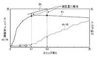
- FIG. 2 is a diagram schematically showing the relationship between the brake braking torque Bt, the road surface reaction force torque Fr, the slip ratio S, and the slip ratio speed ds / dt, where the horizontal axis represents the slip ratio S and the vertical axis.
- the line representing the road surface reaction torque Fr has substantially the same shape as the tire ⁇ -S (friction coefficient-slip rate) line of the wheel 3.
- the slip rate speed ds / dt of the wheel 3 is a value reflecting a deviation between the brake braking torque Bt and the road surface reaction torque Fr.
- the slip rate speed ds / dt increases as the deviation between the brake braking torque Bt and the road reaction torque Fr increases, and decreases as the deviation decreases.
- a drop in the wheel speed of the wheel 3 corresponding to a slip that may occur in the wheel 3 when the braking device 7 is operated appears as a difference between the brake braking torque Bt and the road surface reaction force torque Fr. Therefore, the braking / driving force control unit 14c Is to reflect the slip ratio speed ds / dt in the brake pressure reduction amount when the slip ratio becomes larger than the predetermined value as described above, in other words, to reflect the degree of decrease in the wheel speed of the wheel 3.
- the pressure reduction amount of the brake pressure can be optimized.
- the slip ratio obtained by the slip ratio detector 14a is the target.
- the result is as follows.
- the brake pressure may be insufficiently reduced due to a delay in the brake pressure reduction timing.
- the vehicle control apparatus 1 when the slip ratio becomes larger than the predetermined value as described above, determines the brake pressure based on the slip ratio speed ds / dt (corresponding to the degree of decrease in the wheel speed of the wheel 3). By adjusting the amount of pressure reduction and adjusting the braking force, it is possible to optimize the amount of brake pressure to be reduced and the amount of braking / driving force to be reduced. As a result, the vehicle control apparatus 1 causes the slip ratio obtained by the slip ratio detection unit 14a to deviate from the actual slip ratio.
- the vehicle control apparatus 1 reflects the amount of reduction in brake pressure, more specifically, the amount of reduction in braking force, by the control logic that takes in the slip rate speed in the slip rate control of the wheel 3. As a result, the control accuracy at the time of controlling the slip state of the wheel 3 can be improved.
- control routines are repeatedly executed at a control cycle of several ms to several tens of ms.
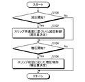
- the braking / driving force control unit 14c of the vehicle control device 1 determines whether or not to start reducing the brake pressure to control the slip state of the wheel 3 (S100). For example, the braking / driving force control unit 14c starts reducing the brake pressure by determining whether or not the slip rate of the wheel 3 obtained by the slip rate detection unit 14a is larger than a predetermined value (target slip rate). It is determined whether or not.
- a predetermined value target slip rate
- the braking / driving force control unit 14c determines to start reducing the brake pressure, that is, when it is determined that the slip rate of the wheel 3 obtained by the slip rate detection unit 14a is greater than a predetermined value (S100: Yes)
- a brake pressure reduction amount is determined based on the slip rate speed (slip rate speed when the slip rate of the wheel 3 exceeds a predetermined value) obtained by the slip rate speed detection unit 14b, and the brake is determined based on the pressure reduction amount.
- the braking force generated on the wheel 3 is reduced by reducing the pressure (S102).
- the braking / driving force control unit 14c obtains the brake pressure reduction amount based on, for example, the control map illustrated in FIG.
- the abscissa indicates the slip rate speed
- the ordinate indicates the brake pressure reduction amount (corresponding to the braking force reduction amount).
- the slip rate speed is such that the braking side slip is in the “positive” direction.
- This control map describes the relationship between the slip rate speed for each reference pressure reduction amount determined according to the acceleration of the vehicle 2 and the vehicle body speed and the brake pressure reduction amount, and the storage unit 15 stores each reference pressure reduction amount. Is stored more than once.
- the amount of brake pressure reduction is larger on the side where the absolute value of the slip ratio speed is relatively larger than on the side where the absolute value of the slip ratio speed is relatively small.
- the braking / driving force control unit 14c detects the acceleration of the vehicle 2, the vehicle body speed, and the slip ratio speed detected by the wheel speed sensor 12, the G sensor 13 and the like when the slip ratio exceeds a predetermined value.
- the brake pressure reduction amount is obtained from the slip ratio speed obtained by the section 14b.
- the braking / driving force control unit 14c may obtain the amount of reduction in brake pressure based on a mathematical expression corresponding to this control map.
- the braking / driving force control unit 14c determines whether or not to start increasing the brake pressure to control the slip state of the wheel 3 (S104). For example, the braking / driving force control unit 14c starts increasing the brake pressure by determining whether or not the slip rate of the wheel 3 obtained by the slip rate detection unit 14a is smaller than a predetermined value (target slip rate). It is determined whether or not to do.
- a predetermined value target slip rate
- the braking / driving force control unit 14c determines to start increasing the brake pressure, that is, when it is determined that the slip rate of the wheel 3 obtained by the slip rate detection unit 14a is smaller than a predetermined value (S104: Yes).
- the brake pressure increase amount is determined based on the slip state such as the current slip ratio, and the brake pressure is increased based on the pressure increase amount to increase the braking force generated in the wheel 3 (S106). End the cycle and move to the next control cycle.
- the braking / driving force control unit 14c determines in S100 that the brake pressure reduction is not started, that is, when it is determined that the slip ratio of the wheel 3 obtained by the slip ratio detection unit 14a is equal to or less than a predetermined value. (S100: No), S102 is skipped, and the processes after S104 are executed.
- the braking / driving force control unit 14c determines in S104 that the brake pressure increase is not started, that is, the slip rate of the wheel 3 obtained by the slip rate detection unit 14a is determined to be equal to or greater than a predetermined value. In the case (S104: No), S106 is skipped to end the current control cycle and shift to the next control cycle.
- the braking / driving force generated on the wheel 3 of the vehicle 2 is controlled to control the slip state of the wheel 3 based on the slip rate speed of the wheel 3. Adjust the amount of driving force reduction. Accordingly, the vehicle control device 1 can improve the control accuracy when controlling the slip state of the wheel 3 by reducing the influence of the operation of the brake pedal 6 by the driver and the influence of the road surface, for example.
- the vehicle control device 1 described above controls the braking / driving force generated on the wheel 3 of the vehicle 2 to control the slip state of the wheel 3, and further increases the inertial mass of the wheel 3 in addition to the slip rate speed of the wheel 3. Based on this, the reduction amount of the braking / driving force may be adjusted.
- the braking / driving force control unit 14c may obtain the brake pressure reduction amount based on the control map according to the modification illustrated in FIG. This control map describes the relationship between the slip rate speed for each reference depressurization amount determined according to the acceleration of the vehicle 2 and the vehicle body speed, the depressurization amount of the brake pressure, and the inertial mass I of the wheel 3. Are stored for each reference decompression amount.
- the amount of brake pressure reduction is larger when the absolute value of the slip ratio speed is relatively larger than the value of the slip ratio speed when the absolute value is relatively smaller.
- the value on the side where the inertial mass 3 is relatively large is larger than the value on the side where the inertial mass of the wheel 3 is relatively small.
- the braking / driving force control unit 14 c obtains a brake pressure reduction amount from the acceleration of the vehicle 2, the vehicle body speed, the slip rate speed, and the inertial mass of the wheel 3.
- the inertial mass of the wheel 3 may be input in advance via an input device, for example.
- the vehicle control device 1 can optimize the brake pressure reduction amount, that is, the braking / driving force reduction amount to a value that also reflects the inertial mass of the wheel 3, so that the slip state of the wheel 3 can be achieved.
- the control accuracy at the time of controlling can be further improved.
- the vehicle control apparatus 1 described above is not limited to the so-called pressure-reducing mode of S102 but also to the pressure-decreasing amount of the brake pressure based on the slip rate speed of the wheel 3, not only during the so-called pressure-increasing mode of S106.
- the reduction amount of braking / driving force may be adjusted.
- the vehicle control device 1 determines that the slip ratio obtained by the slip ratio detection unit 14a is smaller than the target slip ratio S1 (see FIG. 2), and actually shifts to the pressure increasing mode of S106. Even when the slip ratio is larger than the target slip ratio S1, it is possible to more reliably and appropriately prevent the slip state of the wheel 3 from being promoted to the lock tendency side.
- the braking / driving force control unit 14c may obtain the brake pressure reduction amount based on a control map similar to the control map illustrated in FIG.
- the control map in this case may be, for example, a description of the relationship between the slip rate speed for each reference pressure reduction amount determined according to the acceleration of the vehicle 2 and the vehicle body speed, the brake pressure reduction amount, and the slip rate S.
- the amount of brake pressure reduction is larger when the absolute value of the slip ratio speed is relatively larger than the value of the slip ratio speed when the absolute value is relatively smaller.
- the braking / driving force control unit 14c obtains a brake pressure reduction amount from the acceleration of the vehicle 2, the vehicle body speed, the slip rate speed, and the slip speed. In this case, the braking / driving force control unit 14c can optimize the pressure reduction amount of the brake pressure, that is, the reduction amount of the braking / driving force even in the so-called pressure increasing mode. The control accuracy at the time of controlling can be further improved.
- the braking / driving force control unit 14c has been described as performing the determination to start the decrease or increase of the brake pressure based on the slip ratio of the wheel 3, but the present invention is not limited thereto. It may be performed based on a value correlating with the slip ratio or based on the slip ratio speed.
- the braking device 7 has been described as a hydraulic brake device that performs pressure braking using hydraulic pressure, but is not limited thereto.
- the braking device 7 may be any device that can apply a braking force to the wheel 3.
- the braking device 7 generates a braking force on the wheel 3 by so-called regenerative braking using an electric motor that can operate as a generator. Also good.
- the vehicle control device 1 operates when the ABS function is activated in order to suppress a slip that may occur in the wheel 3 when the braking device 7 is activated in response to the depression operation of the brake pedal 6 by the driver.
- the slip ratio control has been described as the braking force control, the present invention is not limited to the braking force control, and can be applied to the slip ratio control as the driving force control. That is, the vehicle control apparatus 1 has the TRC function activated to suppress slip that may occur due to the wheel 3 slipping when the output of the drive source 5 increases in response to the depression of the accelerator pedal 4 by the driver.
- the slip ratio control can also be executed as the driving force control. In this case, in the control maps illustrated in FIGS.
- the horizontal axis may be the slip rate speed when the driving side slip is in the “positive” direction, and the vertical axis may be the reduction amount of the driving force. Even in this case, the vehicle control device 1 can improve the control accuracy when controlling the slip state of the wheel 3 in the slip ratio control (driving force control) when the TRC function is activated.
- the vehicle control device according to the present invention is suitable for application to various vehicle control devices that control the slip state of the wheels of the vehicle.
Landscapes
- Engineering & Computer Science (AREA)
- Transportation (AREA)
- Mechanical Engineering (AREA)
- Microelectronics & Electronic Packaging (AREA)
- Physics & Mathematics (AREA)
- Fluid Mechanics (AREA)
- Chemical & Material Sciences (AREA)
- Combustion & Propulsion (AREA)
- Regulating Braking Force (AREA)
Abstract
車両(2)の車輪(3)に生じる制駆動力を制御して車輪(3)のスリップ状態を制御する際に車輪(3)のスリップ率速度に基づいて制駆動力の低減量を調節することを特徴とするので、車輪(3)のスリップ状態を制御する際の制御精度を向上することができる車両制御装置(1)を提供することができる。この車両制御装置(1)は、典型的には、車輪(3)のスリップ率が予め設定される所定値を超えた際のスリップ率速度に基づいて制駆動力の低減量を調節し、この低減量は、スリップ率速度の絶対値が相対的に大きい側の値がスリップ率速度の絶対値が相対的に小さい側の値と比較して大きくなっている。
Description
本発明は、車両制御装置に関する。
従来の車両制御装置として、例えば、特許文献1には車輪の加速度とスリップ率に応じて演算した路面μに基づいていわゆるABS制御を行うアンチスキッド制御装置が開示されている。 これにより、このアンチスキッド制御装置は、全輪が制動スリップしているアンチスキッド制御中であっても、車体速を精度良く推定し、アンチスキッド制御性能を向上させている。
ところで、上述のような特許文献1に記載されているアンチスキッド制御装置は、例えば、ABS制御などの車輪のスリップ状態を制御する際の制御精度にさらなる改善の余地があった。
本発明は、上記の事情に鑑みてなされたものであって、車輪のスリップ状態を制御する際の制御精度を向上することができる車両制御装置を提供することを目的とする。
上記目的を達成するために、本発明に係る車両制御装置は、車両の車輪に生じる制駆動力を制御して前記車輪のスリップ状態を制御する際に前記車輪のスリップ率速度に基づいて前記制駆動力の低減量を調節することを特徴とする。
また、上記車両制御装置では、前記車輪のスリップ率又は当該スリップ率と相関する値が予め設定される所定値を超えた際の前記スリップ率速度に基づいて前記制駆動力の低減量を調節するものとすることができる。
また、上記車両制御装置では、前記低減量は、前記スリップ率速度の絶対値が相対的に大きい側の値が前記スリップ率速度の絶対値が相対的に小さい側の値と比較して大きいものとすることができる。
また、上記車両制御装置では、前記低減量は、前記車輪の慣性質量が相対的に大きい側の値が前記車輪の慣性質量が相対的に小さい側の値と比較して大きいものとすることができる。
また、上記車両制御装置では、前記低減量は、前記車輪のスリップ率の絶対値が相対的に大きい側の値が前記車輪のスリップ率の絶対値が相対的に小さい側の値と比較して大きいものとすることができる。
本発明に係る車両制御装置は、車両の車輪に生じる制駆動力を制御して車輪のスリップ状態を制御する際に車輪のスリップ率速度に基づいて制駆動力の低減量を調節することから、車輪のスリップ状態を制御する際の制御精度を向上することができる、という効果を奏する。
以下に、本発明に係る車両制御装置の実施形態を図面に基づいて詳細に説明する。なお、この実施形態によりこの発明が限定されるものではない。また、下記実施形態における構成要素には、当業者が置換可能かつ容易なもの、或いは実質的に同一のものが含まれる。
[実施形態]
図1は、実施形態に係る車両制御装置の概略構成図、図2は、実施形態に係るスリップ率速度について説明する線図、図3は、実施形態に係る車両制御装置の制御の一例を説明するフローチャート、図4は、実施形態に係る車両制御装置の制御マップの一例、図5は、変形例に係る車両制御装置の制御マップの一例である。
図1は、実施形態に係る車両制御装置の概略構成図、図2は、実施形態に係るスリップ率速度について説明する線図、図3は、実施形態に係る車両制御装置の制御の一例を説明するフローチャート、図4は、実施形態に係る車両制御装置の制御マップの一例、図5は、変形例に係る車両制御装置の制御マップの一例である。
本実施形態の車両制御装置1は、図1に示すように、車両2に搭載され、車両2の車輪3に生じる制駆動力を制御して車輪3のスリップ状態を制御するものである。車両2は、車両制御装置1、車輪3、アクセルペダル4、駆動源5、ブレーキペダル6、制動装置7などを備える。車両2は、運転者によるアクセルペダル4の操作に応じて駆動源5が動力(トルク)を発生させ、この動力が変速機、差動装置、ドライブシャフトなどの動力伝達装置(不図示)を介して車輪3に伝達され、この車輪3に駆動力を発生させる。また、車両2は、運転者によるブレーキペダル6の操作に応じて制動装置7が作動することで車輪3に制動力を発生させる。
駆動源5は、内燃機関や電動機などの走行用の動力源である。制動装置7は、マスタシリンダ8からアクチュエータ9を介してホイールシリンダ10に接続する油圧経路に作動流体であるブレーキオイルが充填された種々の公知の油圧ブレーキ装置である。制動装置7は、基本的には運転者がブレーキペダル6を操作することで、ブレーキペダル6に作用するペダル踏力(操作力)に応じてマスタシリンダ8によりブレーキオイルにマスタシリンダ圧(操作圧力)が付与される。そして、制動装置7は、このマスタシリンダ圧が各ホイールシリンダ10にてホイールシリンダ圧(制動圧力)として作用することで、キャリパ、ブレーキパッド、ディスクロータなどを含んで構成される油圧制動部11が作動し車輪3に圧力制動力を発生させる。この間、制動装置7は、アクチュエータ9によってホイールシリンダ圧が運転状態に応じて適宜調圧される。
より具体的に言うと、アクチュエータ9は、例えば、車両制御装置1により制御される油圧制御装置(油圧制御回路)によって構成される。アクチュエータ9は、複数の配管、オイルリザーバ、オイルポンプ、各車輪3にそれぞれ設けられた各ホイールシリンダ10に接続する各油圧配管、各油圧配管の油圧を各々に増圧、減圧、保持するための複数の電磁弁などを含んで構成される。
アクチュエータ9は、通常の運転時には、例えば、車両制御装置1の制御指令にしたがってオイルポンプや所定の電磁弁が駆動することで、運転者によるブレーキペダル6の操作量(踏み込み量)に応じてホイールシリンダ10に作用するホイールシリンダ圧を調圧することができる。また、アクチュエータ9は、後述する車両制御時には、例えば、車両制御装置1の制御指令にしたがってオイルポンプや所定の電磁弁が駆動することで、ホイールシリンダ10に作用するホイールシリンダ圧を増圧する増圧モード、ほぼ一定に保持する保持モード、減圧する減圧モードなどで作動可能である。アクチュエータ9は、車両制御装置1による制御によって、車両2の走行状態に応じて各車輪3にそれぞれ設けられたホイールシリンダ10ごとに個別に上記モードを設定することができる。すなわち、アクチュエータ9は、運転者によるブレーキペダル6の操作とは無関係に車両2の走行状態に応じて各車輪3に作用する制動力を個別に調節することができる。
ここで、車両制御装置1は、CPU、ROM、RAM及びインターフェースを含む周知のマイクロコンピュータを主体とする電子回路を含んで構成される。車両制御装置1は、車両2の各所に取り付けられた種々のセンサ、例えば、各車輪3の車輪速度をそれぞれ検出する各車輪速度センサ12や車両2に作用する加速度を検出するGセンサ(加速度センサ)13などが検出した検出結果に対応した電気信号が入力される。車両制御装置1は、各種センサから入力された各種入力信号や各種マップに基づいて、格納されている制御プログラムを実行することにより駆動源5やアクチュエータ9を制御する。
本実施形態の車両制御装置1は、車両2の走行状態に応じて駆動源5やアクチュエータ9を制御することで、車両2のABS(Antilock Brake System)機能やTRC(Traction Control System)機能などを実現することができる。すなわち、車両制御装置1は、運転者によるアクセルペダル4の踏み込み操作(加速操作)やブレーキペダル6の踏み込み操作(制動操作)に伴って車輪3がスリップしたとき、そのスリップ状態にある車輪3の制駆動力を調節することで、車両2の走行状態に応じた最適な制駆動力を車輪3に対して付与するようにする。車両制御装置1は、駆動源5の出力や制動装置7の制動圧力としてのホイールシリンダ圧(以下、特に断りのない限り「ブレーキ圧」という)を調節し車輪3に生じる制駆動力を制御することで、車輪3のスリップ状態、例えば、車輪3のタイヤと路面とのスリップ(滑り)をあらわす指標である車輪3のスリップ率を制御する。車両制御装置1は、実際のスリップ率が目標のスリップ率になるように車輪3に生じる制駆動力を制御する。ここで、目標のスリップ率は、例えば、車輪3のタイヤの摩擦係数が最大となるピークμスリップ率の近傍のスリップ率である。車両制御装置1は、車両2のABS機能やTRC機能を実現するべく、車両2の走行状態に応じてこのスリップ率の制御(スリップ率制御)を実行する。
例えば、車両制御装置1は、運転者によるブレーキペダル6の踏み込み操作に応じて制動装置7が作動した際に車輪3に生じうるスリップを抑制するためにABS機能が作動したときの制動力制御として上記スリップ率制御を実行する。この場合、車両制御装置1は、実際のスリップ率が目標のスリップ率になるように制動装置7のブレーキ圧を調節し車輪3に生じる制動力を制御する。車両制御装置1は、実際のスリップ率が目標のスリップ率より大きくなった場合にブレーキ圧を減圧し制動力を低減する一方、実際のスリップ率が目標のスリップ率より小さくなった場合にブレーキ圧を増圧し制動力を増加する。車両制御装置1は、これを繰り返すことでブレーキロックを防止しつつ車両2の制動距離を短くすることができると共に車両安定性や操舵性を向上することができる。
ところで、車両制御装置1は、上記のようなスリップ率制御において、例えば、車輪3のスリップ率あるいは実質的にスリップ率に相当するパラメータに基づいて制動装置7のブレーキ圧の減圧開始を判定する場合、例えば、スリップ率の検出精度によっては実際のスリップ率が狙いのスリップ率であるピークμスリップ率を過ぎたポイントで減圧が開始されるおそれがある。この場合、車両制御装置1は、スリップ回復のために大きな減圧が必要となったり、減圧不足で車輪3がロック傾向になったりするおそれがある。これは例えば、判定に用いる車輪3のスリップ率自体があくまでも推定値であり、また、走行している路面μ(例えば雪道とか)などに応じて車輪3のタイヤμ-S(摩擦係数-スリップ率)特性やタイヤの摩擦係数が最大となるピークμスリップ率も変動するためであり、これにより減圧開始の判定にバラツキが生じるおそれがある。特に素早い減圧が必要とされる初回の減圧量を例えば車両2の車体に作用する加速度、車速など(のみ)に応じて設定する構成では、狙いのスリップ率で減圧を開始できなかった場合には最適な減圧量、言い換えれば最適な制駆動力の低減量を出力しづらくなるおそれがある。
そこで、本実施形態の車両制御装置1は、車両2の車輪3に生じる制駆動力を制御して車輪3のスリップ状態を制御する際に車輪3のスリップ率速度に基づいて制駆動力の低減量を調節することで、車輪3のスリップ状態を制御する際の制御精度の向上を図っている。なお、以下の説明では、ABS機能が作動したときのスリップ率制御(制動力制御)について説明する。
車両制御装置1は、種々の処理を行う処理部14、車両2の各部を制御するコンピュータプログラムなどが格納された記憶部15及び車両2の各部を駆動する不図示の駆動回路、各種センサが接続される入出力部16を含んで構成され、これらが互いに接続され、互いに信号の受け渡しが可能になっている。そして、車両制御装置1は、処理部14に機能概念的に、車両2の走行状態に応じて車輪3のスリップ率を求めるスリップ率検出部14aと、車両2の走行状態に応じて車輪3のスリップ率速度を求めるスリップ率速度検出部14bと、車両2の車輪3に作用する制駆動力を制御する制駆動力制御部14cとが設けられる。
スリップ率検出部14aは、種々の公知の手法を用いて車輪3のスリップ率を求める。スリップ率検出部14aは、例えば、車輪速度センサ12が検出した各車輪3の車輪速度Vwと、各車輪3の車輪速度Vwから推定される車両2の車体速度Vrとに基づき、下記数式(1)を用いてスリップ率Sを求める。なお、スリップ率は、各車輪速度センサ12による各検出値に基づいて各車輪3に対応してそれぞれ演算されている。以下、特に断りのない限り、このスリップ率に関する演算、判定、制御などは、各車輪3に応じてそれぞれ行われているものとして説明する。
S=[(Vr-Vw)/Vr]×100 ・・・ (1)
S=[(Vr-Vw)/Vr]×100 ・・・ (1)
スリップ率速度検出部14bは、種々の公知の手法を用いて車輪3のスリップ率速度を求める。スリップ率速度検出部14bは、例えば、スリップ率検出部14aが求めたスリップ率の微分値を演算したりスリップ率の単位時間当たりの変化量を演算したり車輪加速度を演算したりすることで車輪3のスリップ率速度(言い換えればスリップ率の変化速度)ds/dtを求めることができる。
制駆動力制御部14cは、スリップ率検出部14aが求めたスリップ率が予め設定される所定値を超えた際に、車輪3と路面との間に生じるスリップを抑制するように制駆動力を制御する。ここで、所定値は、上述したピークμスリップ率に応じて予め設定される狙いのスリップ率である。この所定値は、所定の範囲を有していてもよい。ここでは、制駆動力制御部14cは、制動装置7のアクチュエータ9を制御することで、スリップ率がこの所定値(狙いのスリップ率)より大きくなった場合にブレーキ圧を減圧し制動力を低減する一方、実際のスリップ率が所定値より小さくなった場合にブレーキ圧を増圧し制動力を増加する。
このとき、制駆動力制御部14cは、スリップ率が所定値より大きくなった際の制動力の低減量を車輪3のスリップ率速度に応じた低減量とする。制駆動力制御部14cは、車輪3のスリップ率(又は当該スリップ率と相関する値)が上記所定値を超えた際のスリップ率速度に基づいて制駆動力の低減量を調節する。ここでは、制駆動力制御部14cは、制動装置7のブレーキ圧の減圧量を車輪3のスリップ率速度に応じて調節することで、制動力の低減量を車輪3のスリップ率速度に応じた低減量とする。
さらに具体的に言えば、制駆動力制御部14cは、スリップ率が所定値より大きくなった際に車輪速度センサ12、Gセンサ13などが検出した車両2の加速度や車体速度に応じて定まる基準の減圧量をスリップ率速度に基づいて変更したもの(補正したもの)を実際に適用する減圧量とする。ここで車両2の加速度は、車両2が走行中の路面μなど路面状態をあらわす指標である。つまり、制駆動力制御部14cは、例えば、車両2の加速度や車体速度などに加えて、さらに車輪3のスリップ率速度を加味してブレーキ圧の減圧量を設定する。制駆動力制御部14cは、例えば、車両2の加速度、車体速度、スリップ率速度とブレーキ圧の減圧量との関係が記述された制御マップ(例えば、図4参照)を用いてブレーキ圧の減圧量を算出してもよいし、車両2の加速度と車体速度とに応じて算出された基準の減圧量にスリップ率速度に応じた比例項を乗算して実際に適用するブレーキ圧の減圧量を算出してもよい。
そして、上記制動力の低減量、言い換えれば、ブレーキ圧の減圧量は、スリップ率速度の絶対値が相対的に大きい側の値がスリップ率速度の絶対値が相対的に小さい側の値と比較して大きい。つまり、制駆動力制御部14cは、スリップ率速度の絶対値が相対的に大きい側でのブレーキ圧の減圧量をスリップ率速度の絶対値が相対的に小さい側でのブレーキ圧の減圧量より大きくする。なお、スリップ率が所定値より小さくなった際の制動力の増加量、言い換えれば、ブレーキ圧の増圧量は、現在のスリップ率などに応じて適宜設定されればよい。
ここで、車両2の制動時における車輪3の運動方程式は、例えば、下記の数式(2)のようにあらわすことができる。数式(2)中、「I」は車輪3の慣性質量、「ω」は車輪3の角速度、「dω」は車輪3の角加速度、「Fr」は路面から車輪3に作用する路面反力トルク、「Bt」は制動装置7により車輪3に生じるブレーキ制動トルクである。
I・dω=Fr-Bt ・・・ (2)
I・dω=Fr-Bt ・・・ (2)
そして、図2は、上記ブレーキ制動トルクBt、路面反力トルクFr、スリップ率S及びスリップ率速度ds/dtの関係を模式的に表した線図であり、横軸をスリップ率S、縦軸をスリップ率速度ds/dt、トルクBt、Frとしている。この図において、路面反力トルクFrをあらわす線は、車輪3のタイヤμ-S(摩擦係数-スリップ率)線とほぼ同じ形になっている。本図に示すように、車輪3のスリップ率速度ds/dtは、ブレーキ制動トルクBtと路面反力トルクFrとの偏差を反映した値となる。スリップ率速度ds/dtは、ブレーキ制動トルクBtと路面反力トルクFrとの偏差が大きくなると大きくなり、前記偏差が小さくなると小さくなる。制動装置7が作動した際に車輪3に生じうるスリップに応じた車輪3の車輪速度の落ち込みは、このブレーキ制動トルクBtと路面反力トルクFrとの差分としてあらわれるので、制駆動力制御部14cは、上記のようにスリップ率が所定値より大きくなった際のブレーキ圧の減圧量にスリップ率速度ds/dtを反映させることで、言い換えれば、車輪3の車輪速度の落ち込み度合いを反映させることで、ブレーキ圧の減圧量を適正化することができる。
例えば、図2に例示するように、スリップ率が狙いのスリップ率(目標のスリップ率)S1となるように制駆動力を制御する際、例えば、スリップ率検出部14aが求めたスリップ率が狙いのスリップ率S1より大きくなったときにブレーキ圧を減圧しても、検出精度の誤差に起因して実際のスリップ率が狙いのスリップ率S1より大きいスリップ率S2であった場合には、結果的にブレーキ圧の減圧のタイミングが遅れてブレーキ圧の減圧が不足するおそれがある。
しかしながら、本実施形態の車両制御装置1は、上記のようにスリップ率が所定値より大きくなった際にスリップ率速度ds/dt(車輪3の車輪速度の落ち込み度合いに相当)に基づいてブレーキ圧の減圧量を調節し制動力を調節することで、ブレーキ圧の減圧量を適正化し制駆動力の低減量を適正化することができる。この結果、車両制御装置1は、実際のスリップ率に対してスリップ率検出部14aが求めたスリップ率がずれており、結果的にブレーキ圧の減圧のタイミングが遅れた場合であってもスリップ率速度ds/dtに応じた減圧量でブレーキ圧を減圧し制動力の低減することで、ブレーキ圧の減圧不足によって大きなスリップが発生することを抑制することができ、また、スリップが発生している状態から復帰するために、ブレーキ圧の大きな減圧が必要になることを抑制することができる。また、車両制御装置1は、スリップ率制御において外乱や設計誤差などの不確定な変動に対して適正に対応でき、いわゆるロバスト性を向上することができる。したがって、この車両制御装置1は、車輪3のスリップ率制御においてスリップ率速度を取り込む制御ロジックによって、ブレーキ圧の減圧量、さらに言えば、制動力の低減量を車輪3のスリップ率速度を反映させた値として適正化することができ、車輪3のスリップ状態を制御する際の制御精度を向上することができる。
次に、図3のフローチャートを参照して車両制御装置1における制御の一例を説明する。なお、これらの制御ルーチンは、数msないし数十ms毎の制御周期で繰り返し実行される。
まず、車両制御装置1の制駆動力制御部14cは、車輪3のスリップ状態を制御すべくブレーキ圧の減圧を開始するか否かを判定する(S100)。制駆動力制御部14cは、例えば、スリップ率検出部14aによって求められた車輪3のスリップ率が所定値(狙いのスリップ率)より大きいか否かを判定することでブレーキ圧の減圧を開始するか否かを判定する。
制駆動力制御部14cは、ブレーキ圧の減圧を開始すると判定した場合、すなわち、スリップ率検出部14aによって求められた車輪3のスリップ率が所定値より大きいと判定した場合(S100:Yes)、スリップ率速度検出部14bによって求められたスリップ率速度(車輪3のスリップ率が所定値を超えた際のスリップ率速度)に基づいてブレーキ圧の減圧量を決定し、この減圧量に基づいてブレーキ圧を減圧し車輪3に生じる制動力を低減する(S102)。
制駆動力制御部14cは、例えば、図4に例示する制御マップに基づいてブレーキ圧の減圧量を求める。この制御マップは、横軸がスリップ率速度、縦軸がブレーキ圧の減圧量(制動力の低減量に相当)を示す。ここでのスリップ率速度は、制動側スリップを「正」方向としている。この制御マップは、車両2の加速度や車体速度に応じて定まる基準の減圧量ごとのスリップ率速度とブレーキ圧の減圧量との関係を記述したものであり、記憶部15に基準の減圧量ごとに複数格納されている。この制御マップでは、ブレーキ圧の減圧量は、スリップ率速度の絶対値が相対的に大きい側の値がスリップ率速度の絶対値が相対的に小さい側の値と比較して大きくなっている。制駆動力制御部14cは、この制御マップに基づいて、スリップ率が所定値より大きくなった際に車輪速度センサ12、Gセンサ13などが検出した車両2の加速度や車体速度、スリップ率速度検出部14bが求めたスリップ率速度からブレーキ圧の減圧量を求める。この図4の制御マップでは、例えば、スリップ率速度=0のときの減圧量が車体に作用する加速度と車体速度などに応じて決まる基準の減圧量に相当する。なお、制駆動力制御部14cは、この制御マップに相当する数式に基づいてブレーキ圧の減圧量を求めてもよい。
次に、制駆動力制御部14cは、車輪3のスリップ状態を制御すべくブレーキ圧の増圧を開始するか否かを判定する(S104)。制駆動力制御部14cは、例えば、スリップ率検出部14aによって求められた車輪3のスリップ率が所定値(狙いのスリップ率)より小さいか否かを判定することでブレーキ圧の増圧を開始するか否かを判定する。
制駆動力制御部14cは、ブレーキ圧の増圧を開始すると判定した場合、すなわち、スリップ率検出部14aによって求められた車輪3のスリップ率が所定値より小さいと判定した場合(S104:Yes)、現在のスリップ率などのスリップ状態に基づいてブレーキ圧の増圧量を決定し、この増圧量に基づいてブレーキ圧を増圧し車輪3に生じる制動力を増加し(S106)、現在の制御周期を終了し、次の制御周期に移行する。
制駆動力制御部14cは、S100にて、ブレーキ圧の減圧を開始しないと判定した場合、すなわち、スリップ率検出部14aによって求められた車輪3のスリップ率が所定値以下であると判定した場合(S100:No)、S102をとばしてS104以降の処理を実行する。制駆動力制御部14cは、S104にて、ブレーキ圧の増圧を開始しないと判定した場合、すなわち、スリップ率検出部14aによって求められた車輪3のスリップ率が所定値以上であると判定した場合(S104:No)、S106をとばして現在の制御周期を終了し、次の制御周期に移行する。
以上で説明した実施形態に係る車両制御装置1によれば、車両2の車輪3に生じる制駆動力を制御して車輪3のスリップ状態を制御する際に車輪3のスリップ率速度に基づいて制駆動力の低減量を調節する。したがって、車両制御装置1は、例えば、運転者によるブレーキペダル6の踏み方などの操作や路面の影響を低減して、車輪3のスリップ状態を制御する際の制御精度を向上することができる。
なお、上述した本発明の実施形態に係る車両制御装置は、上述した実施形態に限定されず、請求の範囲に記載された範囲で種々の変更が可能である。
以上で説明した車両制御装置1は、車両2の車輪3に生じる制駆動力を制御して車輪3のスリップ状態を制御する際に車輪3のスリップ率速度に加えてさらに車輪3の慣性質量に基づいて制駆動力の低減量を調節するように構成してもよい。この場合、制駆動力制御部14cは、例えば、図5に例示する変形例に係る制御マップに基づいてブレーキ圧の減圧量を求めるようにすればよい。この制御マップは、車両2の加速度や車体速度に応じて定まる基準の減圧量ごとのスリップ率速度、ブレーキ圧の減圧量及び車輪3の慣性質量Iの関係を記述したものであり、記憶部15に基準の減圧量ごとに複数格納されている。この制御マップでは、ブレーキ圧の減圧量は、スリップ率速度の絶対値が相対的に大きい側の値がスリップ率速度の絶対値が相対的に小さい側の値と比較して大きくなると共に、車輪3の慣性質量が相対的に大きい側の値が車輪3の慣性質量が相対的に小さい側の値と比較して大きくなっている。制駆動力制御部14cは、この制御マップに基づいて、車両2の加速度、車体速度、スリップ率速度、車輪3の慣性質量からブレーキ圧の減圧量を求める。車輪3の慣性質量は、例えば、入力装置などを介して予め入力しておいてもよい。この場合、車両制御装置1は、ブレーキ圧の減圧量、さらに言えば、制駆動力の低減量を車輪3の慣性質量も反映させた値に適正化することができるので、車輪3のスリップ状態を制御する際の制御精度をさらに向上することができる。
また、以上で説明した車両制御装置1は、S102のいわゆる減圧モード中だけでなく、S106のいわゆる増圧モード中においても、車輪3のスリップ率速度に基づいてブレーキ圧の減圧量、さらに言えば、制駆動力の低減量を調節するようにしてもよい。この場合、車両制御装置1は、仮にスリップ率検出部14aが求めたスリップ率が狙いのスリップ率S1(図2参照)より小さいと判定しS106の増圧モードに移行したにもかかわらず実際のスリップ率が狙いのスリップ率S1より大きくなっている場合であっても、車輪3のスリップ状態がロック傾向側に助長されてしまうことをより確実、適正に防止することができる。
この場合、制駆動力制御部14cは、例えば、図5に例示した制御マップと同様な制御マップに基づいてブレーキ圧の減圧量を求めるようにすればよい。この場合の制御マップは、例えば、車両2の加速度や車体速度に応じて定まる基準の減圧量ごとのスリップ率速度、ブレーキ圧の減圧量及びスリップ率Sの関係を記述したものとすればよい。この制御マップでは、ブレーキ圧の減圧量は、スリップ率速度の絶対値が相対的に大きい側の値がスリップ率速度の絶対値が相対的に小さい側の値と比較して大きくなると共に、車輪3のスリップ率が相対的に大きい側の値(すなわち減圧モード側の値)が車輪3のスリップ率が相対的に小さい側の値(すなわち増圧モード側の値)と比較して大きくなっている。制駆動力制御部14cは、この制御マップに基づいて、車両2の加速度、車体速度、スリップ率速度、スリップ速度からブレーキ圧の減圧量を求める。この場合、制駆動力制御部14cは、いわゆる増圧モード中であってもブレーキ圧の減圧量、さらに言えば、制駆動力の低減量を適正化することができるので、車輪3のスリップ状態を制御する際の制御精度をさらに向上することができる。
また、以上の説明では、制駆動力制御部14cは、ブレーキ圧の減圧又は増圧を開始する判定を車輪3のスリップ率に基づいて行うものとして説明したがこれに限らず、例えば、車輪3のスリップ率と相関する値に基づいて行ってもよいし、スリップ率速度に基づいて行ってもよい。
また、以上の説明では、制動装置7は、油圧を用いた圧力制動を行う油圧ブレーキ装置であるものとして説明したがこれに限らない。制動装置7は、車輪3に制動力を作用させることができるものであればなんでもよく、例えば、発電機として作動可能な電動機などによっていわゆる回生制動により車輪3に制動力を発生させるものであってもよい。
また、以上の説明では、車両制御装置1は、運転者によるブレーキペダル6の踏み込み操作に応じて制動装置7が作動した際に車輪3に生じうるスリップを抑制するためにABS機能が作動したときの制動力制御としてスリップ率制御を説明したが制動力制御に限定されるものではなく、駆動力制御としてのスリップ率制御に適用することもできる。すなわち、車両制御装置1は、運転者によるアクセルペダル4の踏み込み操作に応じて駆動源5の出力が増加した際に車輪3が空転することで生じうるスリップを抑制するためにTRC機能が作動したときの駆動力制御として上記スリップ率制御を実行することもできる。この場合、図4や図5で例示した制御マップは、横軸を、駆動側スリップを「正」方向とした場合のスリップ率速度、縦軸を、駆動力の低減量とすればよい。この場合であっても車両制御装置1は、TRC機能が作動したときのスリップ率制御(駆動力制御)において、車輪3のスリップ状態を制御する際の制御精度を向上することができる。
以上のように本発明に係る車両制御装置は、車両の車輪のスリップ状態を制御する種々の車両制御装置に適用して好適である。
1 車両制御装置
2 車両
3 車輪
4 アクセルペダル
5 駆動源
6 ブレーキペダル
7 制動装置
8 マスタシリンダ
9 アクチュエータ
10 ホイールシリンダ
11 油圧制動部
12 車輪速度センサ
13 Gセンサ
14a スリップ率検出部
14b スリップ率速度検出部
14c 制駆動力制御部
2 車両
3 車輪
4 アクセルペダル
5 駆動源
6 ブレーキペダル
7 制動装置
8 マスタシリンダ
9 アクチュエータ
10 ホイールシリンダ
11 油圧制動部
12 車輪速度センサ
13 Gセンサ
14a スリップ率検出部
14b スリップ率速度検出部
14c 制駆動力制御部
Claims (5)
- 車両の車輪に生じる制駆動力を制御して前記車輪のスリップ状態を制御する際に前記車輪のスリップ率速度に基づいて前記制駆動力の低減量を調節することを特徴とする、
車両制御装置。 - 前記車輪のスリップ率又は当該スリップ率と相関する値が予め設定される所定値を超えた際の前記スリップ率速度に基づいて前記制駆動力の低減量を調節する、
請求項1に記載の車両制御装置。 - 前記低減量は、前記スリップ率速度の絶対値が相対的に大きい側の値が前記スリップ率速度の絶対値が相対的に小さい側の値と比較して大きい、
請求項1又は請求項2に記載の車両制御装置。 - 前記低減量は、前記車輪の慣性質量が相対的に大きい側の値が前記車輪の慣性質量が相対的に小さい側の値と比較して大きい、
請求項1乃至請求項3のいずれか1項に記載の車両制御装置。 - 前記低減量は、前記車輪のスリップ率の絶対値が相対的に大きい側の値が前記車輪のスリップ率の絶対値が相対的に小さい側の値と比較して大きい、
請求項1乃至請求項4のいずれか1項に記載の車両制御装置。
Priority Applications (1)
| Application Number | Priority Date | Filing Date | Title |
|---|---|---|---|
| PCT/JP2010/053361 WO2011108083A1 (ja) | 2010-03-02 | 2010-03-02 | 車両制御装置 |
Applications Claiming Priority (1)
| Application Number | Priority Date | Filing Date | Title |
|---|---|---|---|
| PCT/JP2010/053361 WO2011108083A1 (ja) | 2010-03-02 | 2010-03-02 | 車両制御装置 |
Publications (1)
| Publication Number | Publication Date |
|---|---|
| WO2011108083A1 true WO2011108083A1 (ja) | 2011-09-09 |
Family
ID=44541769
Family Applications (1)
| Application Number | Title | Priority Date | Filing Date |
|---|---|---|---|
| PCT/JP2010/053361 Ceased WO2011108083A1 (ja) | 2010-03-02 | 2010-03-02 | 車両制御装置 |
Country Status (1)
| Country | Link |
|---|---|
| WO (1) | WO2011108083A1 (ja) |
Citations (5)
| Publication number | Priority date | Publication date | Assignee | Title |
|---|---|---|---|---|
| JPH04274914A (ja) * | 1991-02-28 | 1992-09-30 | Nissan Motor Co Ltd | 能動型サスペンション |
| JPH0971231A (ja) * | 1995-09-06 | 1997-03-18 | Nissan Diesel Motor Co Ltd | 車両の制動力制御装置 |
| JPH10175536A (ja) * | 1996-12-19 | 1998-06-30 | Nissan Motor Co Ltd | アンチスキッド制御装置 |
| JP2001114085A (ja) * | 1999-10-18 | 2001-04-24 | Toyota Motor Corp | ブレーキシステム用液圧制御装置 |
| JP2001260839A (ja) * | 2000-03-21 | 2001-09-26 | Bosch Braking Systems Co Ltd | 車両用制動圧力制御方法 |
-
2010
- 2010-03-02 WO PCT/JP2010/053361 patent/WO2011108083A1/ja not_active Ceased
Patent Citations (5)
| Publication number | Priority date | Publication date | Assignee | Title |
|---|---|---|---|---|
| JPH04274914A (ja) * | 1991-02-28 | 1992-09-30 | Nissan Motor Co Ltd | 能動型サスペンション |
| JPH0971231A (ja) * | 1995-09-06 | 1997-03-18 | Nissan Diesel Motor Co Ltd | 車両の制動力制御装置 |
| JPH10175536A (ja) * | 1996-12-19 | 1998-06-30 | Nissan Motor Co Ltd | アンチスキッド制御装置 |
| JP2001114085A (ja) * | 1999-10-18 | 2001-04-24 | Toyota Motor Corp | ブレーキシステム用液圧制御装置 |
| JP2001260839A (ja) * | 2000-03-21 | 2001-09-26 | Bosch Braking Systems Co Ltd | 車両用制動圧力制御方法 |
Similar Documents
| Publication | Publication Date | Title |
|---|---|---|
| JP5252118B2 (ja) | 車両制御装置 | |
| JP5273289B2 (ja) | 車両状態演算装置及び車両制御装置 | |
| JP5333466B2 (ja) | フェード判定装置及び制動装置 | |
| JP5267741B1 (ja) | 車両制御装置 | |
| WO2015064771A1 (en) | Braking force control method for vehicle | |
| JP5506632B2 (ja) | 車両用ブレーキ装置 | |
| KR101888454B1 (ko) | 통합형 전자제어장치의 페일 세이프 제어장치 및 제어방법 | |
| JP5215279B2 (ja) | 車両用ブレーキ圧制御装置 | |
| JP6318795B2 (ja) | 車両用旋回走行制御装置、車両用旋回走行制御方法 | |
| KR102325692B1 (ko) | 차량의 구동 제어 방법 및 장치 | |
| JP5228815B2 (ja) | ブレーキ制御装置 | |
| WO2011108083A1 (ja) | 車両制御装置 | |
| JP2676726B2 (ja) | アンチスキツド制御装置 | |
| JP5821830B2 (ja) | 制動力制御装置及び制御装置 | |
| JP4697430B2 (ja) | タイヤ前後力推定装置 | |
| JP5849740B2 (ja) | 車両制御装置 | |
| JP5966994B2 (ja) | 車両用ブレーキ制御装置 | |
| JP5892023B2 (ja) | 制動力制御装置 | |
| JP4792763B2 (ja) | アンチロックブレーキ制御装置 | |
| JP4602186B2 (ja) | 車両用ブレーキ液圧制御装置 | |
| JP2007030748A (ja) | 横加速度計算方法および横加速度計算装置 | |
| JP3868155B2 (ja) | 車両挙動制御装置 | |
| JP2009196494A (ja) | 車輌走行制御装置 | |
| JP2006264614A (ja) | ブレーキ振動検知装置およびそれを備えたブレーキ振動抑制装置 | |
| KR20120137033A (ko) | 차량의 자세제어방법 |
Legal Events
| Date | Code | Title | Description |
|---|---|---|---|
| 121 | Ep: the epo has been informed by wipo that ep was designated in this application |
Ref document number: 10846988 Country of ref document: EP Kind code of ref document: A1 |
|
| NENP | Non-entry into the national phase |
Ref country code: DE |
|
| 122 | Ep: pct application non-entry in european phase |
Ref document number: 10846988 Country of ref document: EP Kind code of ref document: A1 |
|
| NENP | Non-entry into the national phase |
Ref country code: JP |