WO2011105271A1 - 放射線画像撮影装置 - Google Patents
放射線画像撮影装置 Download PDFInfo
- Publication number
- WO2011105271A1 WO2011105271A1 PCT/JP2011/053334 JP2011053334W WO2011105271A1 WO 2011105271 A1 WO2011105271 A1 WO 2011105271A1 JP 2011053334 W JP2011053334 W JP 2011053334W WO 2011105271 A1 WO2011105271 A1 WO 2011105271A1
- Authority
- WO
- WIPO (PCT)
- Prior art keywords
- control unit
- radiation
- unit
- panel
- housing
- Prior art date
Links
- 238000003384 imaging method Methods 0.000 title claims abstract description 150
- 230000005855 radiation Effects 0.000 claims abstract description 363
- 238000006243 chemical reaction Methods 0.000 claims abstract description 142
- 239000000758 substrate Substances 0.000 claims description 58
- 238000004891 communication Methods 0.000 claims description 52
- 238000001514 detection method Methods 0.000 claims description 49
- 230000007246 mechanism Effects 0.000 claims description 40
- 239000000463 material Substances 0.000 claims description 36
- 239000007787 solid Substances 0.000 claims description 21
- 239000004065 semiconductor Substances 0.000 claims description 19
- 229920002457 flexible plastic Polymers 0.000 claims description 2
- 239000012466 permeate Substances 0.000 claims 1
- 239000010408 film Substances 0.000 description 54
- 230000032258 transport Effects 0.000 description 39
- 230000000694 effects Effects 0.000 description 38
- 230000005484 gravity Effects 0.000 description 25
- 239000010410 layer Substances 0.000 description 19
- 238000000034 method Methods 0.000 description 19
- XQPRBTXUXXVTKB-UHFFFAOYSA-M caesium iodide Chemical compound [I-].[Cs+] XQPRBTXUXXVTKB-UHFFFAOYSA-M 0.000 description 18
- 230000000903 blocking effect Effects 0.000 description 17
- 238000003860 storage Methods 0.000 description 14
- 150000002894 organic compounds Chemical class 0.000 description 13
- 230000006870 function Effects 0.000 description 11
- 230000008569 process Effects 0.000 description 11
- 238000010586 diagram Methods 0.000 description 10
- 230000004048 modification Effects 0.000 description 10
- 238000012986 modification Methods 0.000 description 10
- 230000035945 sensitivity Effects 0.000 description 10
- 230000017525 heat dissipation Effects 0.000 description 9
- 230000000149 penetrating effect Effects 0.000 description 9
- OKTJSMMVPCPJKN-UHFFFAOYSA-N Carbon Chemical compound [C] OKTJSMMVPCPJKN-UHFFFAOYSA-N 0.000 description 8
- 239000004760 aramid Substances 0.000 description 8
- 229920003235 aromatic polyamide Polymers 0.000 description 8
- -1 quinacridone organic compounds Chemical class 0.000 description 8
- 239000002041 carbon nanotube Substances 0.000 description 7
- 229910021393 carbon nanotube Inorganic materials 0.000 description 7
- 230000020169 heat generation Effects 0.000 description 7
- OAICVXFJPJFONN-UHFFFAOYSA-N Phosphorus Chemical compound [P] OAICVXFJPJFONN-UHFFFAOYSA-N 0.000 description 6
- 239000011368 organic material Substances 0.000 description 6
- 229910021417 amorphous silicon Inorganic materials 0.000 description 5
- 230000005540 biological transmission Effects 0.000 description 5
- 230000001276 controlling effect Effects 0.000 description 5
- 230000007423 decrease Effects 0.000 description 5
- 238000009826 distribution Methods 0.000 description 5
- 239000011521 glass Substances 0.000 description 5
- 239000002121 nanofiber Substances 0.000 description 5
- 239000003990 capacitor Substances 0.000 description 4
- 150000001875 compounds Chemical class 0.000 description 4
- 239000004020 conductor Substances 0.000 description 4
- 230000007274 generation of a signal involved in cell-cell signaling Effects 0.000 description 4
- 239000011159 matrix material Substances 0.000 description 4
- 239000004033 plastic Substances 0.000 description 4
- 229920003023 plastic Polymers 0.000 description 4
- 238000012545 processing Methods 0.000 description 4
- 239000011347 resin Substances 0.000 description 4
- 229920005989 resin Polymers 0.000 description 4
- 238000012546 transfer Methods 0.000 description 4
- 238000002834 transmittance Methods 0.000 description 4
- 238000009966 trimming Methods 0.000 description 4
- 239000013585 weight reducing agent Substances 0.000 description 4
- XLOMVQKBTHCTTD-UHFFFAOYSA-N Zinc monoxide Chemical compound [Zn]=O XLOMVQKBTHCTTD-UHFFFAOYSA-N 0.000 description 3
- 229910007541 Zn O Inorganic materials 0.000 description 3
- 238000010521 absorption reaction Methods 0.000 description 3
- 238000009825 accumulation Methods 0.000 description 3
- 230000008859 change Effects 0.000 description 3
- 230000008878 coupling Effects 0.000 description 3
- 238000010168 coupling process Methods 0.000 description 3
- 238000005859 coupling reaction Methods 0.000 description 3
- 229910052733 gallium Inorganic materials 0.000 description 3
- 229910052738 indium Inorganic materials 0.000 description 3
- 239000000088 plastic resin Substances 0.000 description 3
- 238000003825 pressing Methods 0.000 description 3
- 229910052725 zinc Inorganic materials 0.000 description 3
- 241000894006 Bacteria Species 0.000 description 2
- 229920002749 Bacterial cellulose Polymers 0.000 description 2
- NRCMAYZCPIVABH-UHFFFAOYSA-N Quinacridone Chemical compound N1C2=CC=CC=C2C(=O)C2=C1C=C1C(=O)C3=CC=CC=C3NC1=C2 NRCMAYZCPIVABH-UHFFFAOYSA-N 0.000 description 2
- 238000000862 absorption spectrum Methods 0.000 description 2
- 230000009471 action Effects 0.000 description 2
- 239000005016 bacterial cellulose Substances 0.000 description 2
- 229920002678 cellulose Polymers 0.000 description 2
- 239000001913 cellulose Substances 0.000 description 2
- 238000001816 cooling Methods 0.000 description 2
- 239000013078 crystal Substances 0.000 description 2
- 238000000151 deposition Methods 0.000 description 2
- 238000002347 injection Methods 0.000 description 2
- 239000007924 injection Substances 0.000 description 2
- 230000001678 irradiating effect Effects 0.000 description 2
- 230000031700 light absorption Effects 0.000 description 2
- 238000012423 maintenance Methods 0.000 description 2
- 229910052751 metal Inorganic materials 0.000 description 2
- 239000002184 metal Substances 0.000 description 2
- 210000001724 microfibril Anatomy 0.000 description 2
- 238000002156 mixing Methods 0.000 description 2
- 239000012044 organic layer Substances 0.000 description 2
- 239000004417 polycarbonate Substances 0.000 description 2
- 238000002601 radiography Methods 0.000 description 2
- 238000005070 sampling Methods 0.000 description 2
- 239000011669 selenium Substances 0.000 description 2
- 239000010409 thin film Substances 0.000 description 2
- 238000007740 vapor deposition Methods 0.000 description 2
- 241000589220 Acetobacter Species 0.000 description 1
- 235000002837 Acetobacter xylinum Nutrition 0.000 description 1
- 239000004925 Acrylic resin Substances 0.000 description 1
- 229920000178 Acrylic resin Polymers 0.000 description 1
- XMWRBQBLMFGWIX-UHFFFAOYSA-N C60 fullerene Chemical compound C12=C3C(C4=C56)=C7C8=C5C5=C9C%10=C6C6=C4C1=C1C4=C6C6=C%10C%10=C9C9=C%11C5=C8C5=C8C7=C3C3=C7C2=C1C1=C2C4=C6C4=C%10C6=C9C9=C%11C5=C5C8=C3C3=C7C1=C1C2=C4C6=C2C9=C5C3=C12 XMWRBQBLMFGWIX-UHFFFAOYSA-N 0.000 description 1
- 241001136169 Komagataeibacter xylinus Species 0.000 description 1
- 239000004695 Polyether sulfone Substances 0.000 description 1
- 239000004642 Polyimide Substances 0.000 description 1
- 239000004793 Polystyrene Substances 0.000 description 1
- BUGBHKTXTAQXES-UHFFFAOYSA-N Selenium Chemical compound [Se] BUGBHKTXTAQXES-UHFFFAOYSA-N 0.000 description 1
- XUIMIQQOPSSXEZ-UHFFFAOYSA-N Silicon Chemical compound [Si] XUIMIQQOPSSXEZ-UHFFFAOYSA-N 0.000 description 1
- 229910006404 SnO 2 Inorganic materials 0.000 description 1
- 229910000831 Steel Inorganic materials 0.000 description 1
- 229910010413 TiO 2 Inorganic materials 0.000 description 1
- BOPGJASFSFBTIY-UHFFFAOYSA-N [O-2].S.[Gd+3] Chemical compound [O-2].S.[Gd+3] BOPGJASFSFBTIY-UHFFFAOYSA-N 0.000 description 1
- 239000004840 adhesive resin Substances 0.000 description 1
- 229920006223 adhesive resin Polymers 0.000 description 1
- 238000013459 approach Methods 0.000 description 1
- QVGXLLKOCUKJST-UHFFFAOYSA-N atomic oxygen Chemical compound [O] QVGXLLKOCUKJST-UHFFFAOYSA-N 0.000 description 1
- 230000004888 barrier function Effects 0.000 description 1
- 238000005452 bending Methods 0.000 description 1
- 239000008280 blood Substances 0.000 description 1
- 210000004369 blood Anatomy 0.000 description 1
- 229910052799 carbon Inorganic materials 0.000 description 1
- 238000005119 centrifugation Methods 0.000 description 1
- 230000000295 complement effect Effects 0.000 description 1
- 239000002131 composite material Substances 0.000 description 1
- 238000002425 crystallisation Methods 0.000 description 1
- 230000008025 crystallization Effects 0.000 description 1
- 238000011161 development Methods 0.000 description 1
- 238000009792 diffusion process Methods 0.000 description 1
- 230000005684 electric field Effects 0.000 description 1
- 230000005611 electricity Effects 0.000 description 1
- 239000007772 electrode material Substances 0.000 description 1
- 238000000295 emission spectrum Methods 0.000 description 1
- 239000003822 epoxy resin Substances 0.000 description 1
- 230000008020 evaporation Effects 0.000 description 1
- 238000001704 evaporation Methods 0.000 description 1
- 230000005284 excitation Effects 0.000 description 1
- 230000001747 exhibiting effect Effects 0.000 description 1
- 239000000835 fiber Substances 0.000 description 1
- 230000005669 field effect Effects 0.000 description 1
- 229910003472 fullerene Inorganic materials 0.000 description 1
- 239000007789 gas Substances 0.000 description 1
- 230000036541 health Effects 0.000 description 1
- 238000003702 image correction Methods 0.000 description 1
- 239000012535 impurity Substances 0.000 description 1
- AMGQUBHHOARCQH-UHFFFAOYSA-N indium;oxotin Chemical compound [In].[Sn]=O AMGQUBHHOARCQH-UHFFFAOYSA-N 0.000 description 1
- 238000007689 inspection Methods 0.000 description 1
- 238000009413 insulation Methods 0.000 description 1
- 239000011229 interlayer Substances 0.000 description 1
- 238000010030 laminating Methods 0.000 description 1
- 238000004519 manufacturing process Methods 0.000 description 1
- 239000012528 membrane Substances 0.000 description 1
- 229910044991 metal oxide Inorganic materials 0.000 description 1
- 150000004706 metal oxides Chemical class 0.000 description 1
- 239000000203 mixture Substances 0.000 description 1
- 239000004745 nonwoven fabric Substances 0.000 description 1
- JFNLZVQOOSMTJK-KNVOCYPGSA-N norbornene Chemical compound C1[C@@H]2CC[C@H]1C=C2 JFNLZVQOOSMTJK-KNVOCYPGSA-N 0.000 description 1
- 230000000474 nursing effect Effects 0.000 description 1
- 229910052760 oxygen Inorganic materials 0.000 description 1
- 239000001301 oxygen Substances 0.000 description 1
- YRZZLAGRKZIJJI-UHFFFAOYSA-N oxyvanadium phthalocyanine Chemical compound [V+2]=O.C12=CC=CC=C2C(N=C2[N-]C(C3=CC=CC=C32)=N2)=NC1=NC([C]1C=CC=CC1=1)=NC=1N=C1[C]3C=CC=CC3=C2[N-]1 YRZZLAGRKZIJJI-UHFFFAOYSA-N 0.000 description 1
- 230000035515 penetration Effects 0.000 description 1
- SLIUAWYAILUBJU-UHFFFAOYSA-N pentacene Chemical compound C1=CC=CC2=CC3=CC4=CC5=CC=CC=C5C=C4C=C3C=C21 SLIUAWYAILUBJU-UHFFFAOYSA-N 0.000 description 1
- IEQIEDJGQAUEQZ-UHFFFAOYSA-N phthalocyanine Chemical class N1C(N=C2C3=CC=CC=C3C(N=C3C4=CC=CC=C4C(=N4)N3)=N2)=C(C=CC=C2)C2=C1N=C1C2=CC=CC=C2C4=N1 IEQIEDJGQAUEQZ-UHFFFAOYSA-N 0.000 description 1
- 229920002493 poly(chlorotrifluoroethylene) Polymers 0.000 description 1
- 229920003207 poly(ethylene-2,6-naphthalate) Polymers 0.000 description 1
- 229920003050 poly-cycloolefin Polymers 0.000 description 1
- 229920001230 polyarylate Polymers 0.000 description 1
- 229920000515 polycarbonate Polymers 0.000 description 1
- 239000005023 polychlorotrifluoroethylene (PCTFE) polymer Substances 0.000 description 1
- 229920000647 polyepoxide Polymers 0.000 description 1
- 229920000728 polyester Polymers 0.000 description 1
- 229920006393 polyether sulfone Polymers 0.000 description 1
- 239000011112 polyethylene naphthalate Substances 0.000 description 1
- 229920000139 polyethylene terephthalate Polymers 0.000 description 1
- 239000005020 polyethylene terephthalate Substances 0.000 description 1
- 229920001721 polyimide Polymers 0.000 description 1
- 229920000642 polymer Polymers 0.000 description 1
- 229920002223 polystyrene Polymers 0.000 description 1
- 238000002360 preparation method Methods 0.000 description 1
- 239000010453 quartz Substances 0.000 description 1
- 230000009467 reduction Effects 0.000 description 1
- 230000001105 regulatory effect Effects 0.000 description 1
- 230000004044 response Effects 0.000 description 1
- 229910052711 selenium Inorganic materials 0.000 description 1
- 229910052710 silicon Inorganic materials 0.000 description 1
- 239000010703 silicon Substances 0.000 description 1
- VYPSYNLAJGMNEJ-UHFFFAOYSA-N silicon dioxide Inorganic materials O=[Si]=O VYPSYNLAJGMNEJ-UHFFFAOYSA-N 0.000 description 1
- 229910052709 silver Inorganic materials 0.000 description 1
- 239000004332 silver Substances 0.000 description 1
- 229910000679 solder Inorganic materials 0.000 description 1
- 239000010959 steel Substances 0.000 description 1
- 239000000126 substance Substances 0.000 description 1
- 230000001629 suppression Effects 0.000 description 1
- 229910052716 thallium Inorganic materials 0.000 description 1
- BKVIYDNLLOSFOA-UHFFFAOYSA-N thallium Chemical compound [Tl] BKVIYDNLLOSFOA-UHFFFAOYSA-N 0.000 description 1
- 238000013519 translation Methods 0.000 description 1
- XLYOFNOQVPJJNP-UHFFFAOYSA-N water Substances O XLYOFNOQVPJJNP-UHFFFAOYSA-N 0.000 description 1
Images


Classifications
-
- A—HUMAN NECESSITIES
- A61—MEDICAL OR VETERINARY SCIENCE; HYGIENE
- A61B—DIAGNOSIS; SURGERY; IDENTIFICATION
- A61B6/00—Apparatus or devices for radiation diagnosis; Apparatus or devices for radiation diagnosis combined with radiation therapy equipment
- A61B6/42—Arrangements for detecting radiation specially adapted for radiation diagnosis
- A61B6/4283—Arrangements for detecting radiation specially adapted for radiation diagnosis characterised by a detector unit being housed in a cassette
-
- A—HUMAN NECESSITIES
- A61—MEDICAL OR VETERINARY SCIENCE; HYGIENE
- A61B—DIAGNOSIS; SURGERY; IDENTIFICATION
- A61B6/00—Apparatus or devices for radiation diagnosis; Apparatus or devices for radiation diagnosis combined with radiation therapy equipment
-
- A—HUMAN NECESSITIES
- A61—MEDICAL OR VETERINARY SCIENCE; HYGIENE
- A61B—DIAGNOSIS; SURGERY; IDENTIFICATION
- A61B6/00—Apparatus or devices for radiation diagnosis; Apparatus or devices for radiation diagnosis combined with radiation therapy equipment
- A61B6/44—Constructional features of apparatus for radiation diagnosis
- A61B6/4488—Means for cooling
-
- G—PHYSICS
- G01—MEASURING; TESTING
- G01T—MEASUREMENT OF NUCLEAR OR X-RADIATION
- G01T1/00—Measuring X-radiation, gamma radiation, corpuscular radiation, or cosmic radiation
- G01T1/16—Measuring radiation intensity
- G01T1/20—Measuring radiation intensity with scintillation detectors
- G01T1/2018—Scintillation-photodiode combinations
- G01T1/20188—Auxiliary details, e.g. casings or cooling
-
- G—PHYSICS
- G01—MEASURING; TESTING
- G01T—MEASUREMENT OF NUCLEAR OR X-RADIATION
- G01T1/00—Measuring X-radiation, gamma radiation, corpuscular radiation, or cosmic radiation
- G01T1/16—Measuring radiation intensity
- G01T1/24—Measuring radiation intensity with semiconductor detectors
-
- G—PHYSICS
- G01—MEASURING; TESTING
- G01T—MEASUREMENT OF NUCLEAR OR X-RADIATION
- G01T1/00—Measuring X-radiation, gamma radiation, corpuscular radiation, or cosmic radiation
- G01T1/16—Measuring radiation intensity
- G01T1/24—Measuring radiation intensity with semiconductor detectors
- G01T1/244—Auxiliary details, e.g. casings, cooling, damping or insulation against damage by, e.g. heat, pressure or the like
-
- G—PHYSICS
- G03—PHOTOGRAPHY; CINEMATOGRAPHY; ANALOGOUS TECHNIQUES USING WAVES OTHER THAN OPTICAL WAVES; ELECTROGRAPHY; HOLOGRAPHY
- G03B—APPARATUS OR ARRANGEMENTS FOR TAKING PHOTOGRAPHS OR FOR PROJECTING OR VIEWING THEM; APPARATUS OR ARRANGEMENTS EMPLOYING ANALOGOUS TECHNIQUES USING WAVES OTHER THAN OPTICAL WAVES; ACCESSORIES THEREFOR
- G03B42/00—Obtaining records using waves other than optical waves; Visualisation of such records by using optical means
- G03B42/02—Obtaining records using waves other than optical waves; Visualisation of such records by using optical means using X-rays
- G03B42/04—Holders for X-ray films
-
- A—HUMAN NECESSITIES
- A61—MEDICAL OR VETERINARY SCIENCE; HYGIENE
- A61B—DIAGNOSIS; SURGERY; IDENTIFICATION
- A61B6/00—Apparatus or devices for radiation diagnosis; Apparatus or devices for radiation diagnosis combined with radiation therapy equipment
- A61B6/04—Positioning of patients; Tiltable beds or the like
-
- A—HUMAN NECESSITIES
- A61—MEDICAL OR VETERINARY SCIENCE; HYGIENE
- A61B—DIAGNOSIS; SURGERY; IDENTIFICATION
- A61B6/00—Apparatus or devices for radiation diagnosis; Apparatus or devices for radiation diagnosis combined with radiation therapy equipment
- A61B6/44—Constructional features of apparatus for radiation diagnosis
- A61B6/4423—Constructional features of apparatus for radiation diagnosis related to hygiene or sterilisation
-
- A—HUMAN NECESSITIES
- A61—MEDICAL OR VETERINARY SCIENCE; HYGIENE
- A61B—DIAGNOSIS; SURGERY; IDENTIFICATION
- A61B6/00—Apparatus or devices for radiation diagnosis; Apparatus or devices for radiation diagnosis combined with radiation therapy equipment
- A61B6/56—Details of data transmission or power supply, e.g. use of slip rings
Definitions
- the present invention relates to a radiation imaging apparatus having a panel unit accommodating a radiation conversion panel for converting radiation into a radiation image, and a control unit for controlling the radiation conversion panel.
- a radiation image capturing apparatus which applies radiation to a subject, guides the radiation transmitted through the subject to a radiation conversion panel, and captures a radiation image.
- a radiation conversion panel a conventional radiation film on which the radiation image is exposed and recorded, or radiation energy as the radiation image is accumulated in a fluorescent material, and the radiation image is irradiated with excitation light to stimulate the radiation image.
- Storage phosphor panels are known which can be extracted as light. These radiation conversion panels supply the radiation film on which the radiation image is recorded to a developing device to perform development processing, or supply the stimulable phosphor panel to a reading device to perform reading processing. A visible image can be obtained.
- the above-described direct conversion type or indirect conversion type radiation conversion panel is accommodated in a panel unit, and a radiation image obtained by the radiation conversion panel is read out by a control unit that controls the radiation conversion panel.
- the panel unit and the control unit constitute a radiation imaging apparatus called an electronic cassette.
- the electronic cassette is preferably configured to be portable by a doctor or a technician (user).
- Japanese Patent Application Laid-Open No. 2008-256685 proposes that a gripping portion gripped by a user be provided integrally with the control portion, and the control portion be configured to be removable from the panel portion.
- Japanese Patent Application Laid-Open No. 2004-77641 proposes that a grip portion be provided on the side surface of the electronic cassette and the grip portion be movable along the side surface.
- Japanese Patent Application Laid-Open No. 2002-82172 proposes that the center of gravity of the electronic cassette be on the center line of the grip portion.
- the panel unit and the control unit are transported in an integrated state in which the panel unit and the control unit are connected, and after transportation, shooting is performed in a state where the control unit is separated from the panel unit. Proposed.
- control unit is equipped with a power supply unit such as a battery for supplying power to the radiation conversion panel and each unit in the control unit, and a communication unit for performing communication with the outside.
- a power supply unit such as a battery for supplying power to the radiation conversion panel and each unit in the control unit
- a communication unit for performing communication with the outside.
- the proportion of the weight of the control unit is large.
- the power supply unit and the communication unit are often arranged in a concentrated manner at a specific place in the control unit. Therefore, depending on the position of the control unit in the electronic cassette, the entire apparatus becomes unbalanced load arrangement, and as a result, when the user grips the grip during transportation, the weight of the electronic cassette is greater than the actual weight. It may feel heavy.
- An object of the present invention is to make it possible to stably carry a radiation imaging apparatus.
- Another object of the present invention is to make it possible to stably carry the radiation imaging apparatus by eliminating the unbalanced load arrangement at the time of transportation of the radiation imaging apparatus.
- a radiation image capturing apparatus controls a radiation conversion panel, which is disposed in the panel unit containing a radiation conversion panel for converting radiation into a radiation image, and the panel unit.
- the control unit is characterized in that the control unit is thicker than the panel unit or provided so as to protrude from the panel unit.
- the thickness of the panel portion thinner than the thickness of the control portion, or by providing the control portion so as to protrude from the panel portion, it is possible to realize thinning and weight reduction of the radiographic imaging device .
- the control unit is disposed at a location other than the region to which the radiation transmitted through the subject is irradiated, more preferably at a location other than the imageable region where the radiation can be irradiated. Ru.
- control unit may move along the surface of the panel unit.
- the radiation image capturing apparatus further includes a moving mechanism for translating the control unit relative to the panel unit along the surface of the panel unit.
- the position of the center of gravity of the radiation imaging device can be easily changed by moving the control unit causing the unbalanced load arrangement in parallel with the panel unit by the moving mechanism. It is possible to
- the control unit is disposed offset with respect to the central position of the geometric shape of the radiation image capturing apparatus. If so, the position of the center of gravity of the radiation image capturing apparatus does not coincide with the center position and becomes eccentric, resulting in an unbalanced load arrangement as the entire apparatus.
- the center position and the center-of-gravity position can be made to substantially coincide with each other, and unbalanced load arrangement can be easily eliminated.
- the radiographic imaging device can be carried stably and easily.
- the radiation imaging apparatus can be transported without hitting the control unit against an arbitrary object or dropping the radiation imaging apparatus, and the burden on the user at the time of transportation can be achieved. Is also mitigated.
- the control unit by moving the control unit in parallel with respect to the panel unit by the moving mechanism, it is possible to easily eliminate unbalanced load arrangement in the radiation image capturing apparatus.
- the user can stably carry the radiation imaging apparatus during transportation.
- the panel unit accommodates the radiation conversion panel in a substantially rectangular first housing capable of transmitting the radiation
- the moving mechanism is configured to capture the image of the surface of the first housing. It is desirable to be comprised from the substantially linear guide part formed in places other than a possible area
- the control unit can be moved relative to the panel unit with a simple mechanism.
- the control unit can be retracted from the imageable area at the time of imaging, so the presence of the control unit and the guide unit There is no hindrance to radiography.
- the moving method of the control unit with respect to the panel unit may be rotational movement instead of the above-described parallel movement. That is, the radiation image capturing apparatus may further include a moving mechanism that rotationally moves the control unit with respect to the panel unit along the surface of the panel unit.
- the center of gravity position of the radiographic imaging device can be easily changed by rotationally moving the control unit causing the unbalanced load arrangement with respect to the panel unit by the moving mechanism. It is possible to
- the center position and the center-of-gravity position can be made to substantially coincide with each other, and unbalanced load arrangement can be easily eliminated. Therefore, as in the case of translating the control unit in parallel, the user feels light in the radiographic imaging device at the time of transportation, and therefore, the radiographic imaging device can be carried stably and easily. As a result, the radiation imaging apparatus can be transported without hitting the control unit against an arbitrary object or dropping the radiation imaging apparatus, and the burden on the user at the time of transportation can be achieved. Is also mitigated.
- the rotational movement of the control unit with respect to the panel unit by the movement mechanism can easily eliminate the unbalanced load arrangement in the radiographic imaging device, so that the user can It is possible to stably carry the radiation imaging apparatus during transportation.
- the panel unit accommodates the radiation conversion panel in the first housing
- the moving mechanism is provided on a surface of the first housing other than the image captureable area. It has a shaft and rotates the control unit about the shaft.
- control unit Since the control unit is rotationally moved about the shaft unit, the control unit can be rotationally moved with respect to the panel unit by a simple mechanism. In addition, even if the control unit is disposed so as to cover the imageable area at the time of transportation, the control unit can be retracted from the imageable area at the time of imaging, so the presence of the control unit and the shaft unit There is no hindrance to radiography.
- control unit drives and controls the radiation conversion panel, and a panel control unit that reads the radiation image from the radiation conversion panel, a communication unit that can communicate with the outside, and the panel control unit The communication unit and a power supply unit that supplies power to the radiation conversion panel.
- connection portion for electrically connecting the radiation conversion panel and the control portion is provided in the panel portion, and the connection portion and the control portion are separated when the control portion is moved, and electrical connection is performed.
- the panel control unit may include a connection detection unit that detects the presence or absence of an electrical connection between the connection unit and the control unit.
- connection detection unit determines the presence or absence of the electrical connection between the connection unit and the control unit. By detecting, the timing of control on the radiation conversion panel and the timing of reading out the radiation image on the radiation conversion panel can be easily grasped.
- the radiation image capturing apparatus can be easily carried by providing the holding unit to be held by the user on the control unit and / or the panel unit.
- the panel unit accommodates the radiation conversion panel in the first housing, and the control unit at least at the time of photographing, a portion of the surface of the first housing other than the imageable area.
- the grip portion is provided on the side surface of the first housing, the upper surface of the substantially rectangular second housing constituting the control unit, and / or the side surface of the second housing.
- the holding unit may include one side surface of the first case, the first It is provided on the other side surface of the case, the other side surface connecting the one side surface and the other side surface, the upper surface of the second case, and / or the side surface of the second case.
- the radiation image capturing apparatus can be easily carried by providing the holding unit on the panel unit.
- control unit when the control unit is provided with the grip unit, the user grips the grip unit and carries the control unit with a relatively large weight during transportation, so that the radiation imaging device can be carried. Stability can be enhanced.
- control unit when the control unit is movable with respect to the panel unit, the user can easily move the control unit with respect to the panel unit while gripping the grip unit.
- the holding unit When the control unit is provided with the holding unit, the holding unit is pulled out from the upper surface or the side surface of the second housing when the radiographic imaging device is transported or when the control unit is moved. It may be gripped. By setting the holding unit to be pulled out only when transporting or moving the control unit, the presence of the holding unit does not interfere with imaging. Thereby, the usability of the radiographic imaging device is improved.
- the radiation conversion panel includes a scintillator for converting the radiation into visible light, a solid detection element for converting the visible light into an electrical signal indicating the radiographic image, and the electric signal from the solid detection element.
- a substrate on which the solid detection device and the switching device are formed the substrate is a flexible plastic substrate, and the solid detection device is an organic photoconductor
- the switching element is made of an organic semiconductor material.
- the radiation conversion panel and the panel unit that accommodates the radiation conversion panel can also be flexible. As a result, the object can be removed from the subject It is possible to avoid the occurrence of breakage or the like of the radiation conversion panel when a load is applied to the part.
- the substrate, the switching element, the solid detection element, and the scintillator composed of CsI are arranged in this order along the radiation direction of the radiation, it is possible to obtain a high quality radiation image.
- a first invention relates to a radiation imaging apparatus having a moving mechanism which moves the control unit in parallel with respect to the panel unit.
- the radiation irradiation surface having the imageable area, and between two opposing sides of at least one of the side surfaces of the first housing.
- the guide portion is formed along a direction substantially perpendicular to the two sides.
- the guide portion can be formed along the longitudinal direction of the first housing, and the moving member and the control portion can be linearly translated integrally along the guide portion. .
- the center position and the center-of-gravity position can be easily made to coincide with each other, and the unbalanced load arrangement can be reliably eliminated.
- the image captureable area may be formed substantially at the center of the irradiation surface, and the two guide portions may be formed so as to sandwich the image captureable area between two opposing sides of the irradiation surface.
- the guide portions may be formed parallel to each other on two opposite side surfaces of the first housing.
- the two moving members are attached to the control unit, and the two moving members are respectively disposed in the two guide portions.
- the control unit and the two moving members can be translated more stably and reliably along the two guide units.
- the guide portion is a recess, a groove or a rail formed in a substantially linear shape on the surface of the first housing, and the movable member can slide linearly in the recess or along the rail. If the sliding portion or the wheel capable of traveling in a straight line along the groove is provided, the control portion can be simply and reliably moved in parallel to the panel portion.
- the stop member capable of stopping the sliding of the sliding portion along the recess or the rail or the traveling of the wheel along the groove is provided in the recess, the groove, or the rail. It is possible to stop the control unit at an arbitrary position with respect to the panel unit.
- the stopping member is formed in the recess, the groove, or the rail, and the sliding of the sliding portion or the traveling of the wheel is stopped by the abutment of the sliding portion or the wheel. If it is a convex portion, the control unit can be reliably stopped at the arbitrary position.
- a second aspect of the present invention relates to a radiation imaging apparatus having a moving mechanism that rotationally moves the control unit with respect to the panel unit.
- the moving mechanism further includes an oblong hole formed in the second case and through which the shaft passes, and the control unit is centered on the shaft. It is sufficient to be able to rotate and move relative to the shaft along the hole.
- the central position is obtained by rotating the control unit with respect to the panel unit around the shaft unit and moving the control unit with respect to the panel unit along the oval hole.
- the center-of-gravity position can be easily matched, and the unbalanced load arrangement can be reliably eliminated.
- the shaft portion is provided at a position other than the imageable area among the irradiation surfaces of the radiation having the imageable area in the first case, and the irradiation side of the second case is provided.
- the oval hole may be formed on the bottom surface along the longitudinal direction of the second housing.
- control unit can be moved more stably and reliably along the longitudinal direction.
- a tip portion of the shaft inserted into the second housing is provided with a protrusion extending in the radial direction of the shaft and having a width substantially the same as the diameter of the shaft
- the bottom surface of the case 2 is provided with a movement restricting member that substantially surrounds the hole and opens at one end of the hole in a plan view, and the shaft is the one end of the hole.
- the movement restricting member restricts the rotation angle range of the control unit, and when the projection is disposed in the hole in a plan view, the movement restricting member contacts the tip of the shaft and the projection. It is desirable to regulate the moving direction of the control unit with respect to the shaft.
- the rotation angle range of the control unit with respect to the shaft portion is set by one end portion and the other end portion of the opening portion of the movement restricting member, and the projection portion.
- the moving direction of the control unit with respect to the shaft unit is set by the unit and the protrusion. Further, the moving amount of the control unit along the moving direction is also set by the length of the oval hole.
- a stop member capable of stopping the movement of the control unit along the hole by being in contact with the protrusion is disposed on the side of the hole of the movement restricting member, it is possible to the panel portion. It is possible to stop the control unit at any position.
- control unit can be reliably stopped at the arbitrary position as long as the stopping member is a convex portion that stops the movement of the control unit by the abutment of the projection.
- the movement mechanism further includes a hole formed in the second housing and through which the shaft passes, and the control unit is rotatable around the shaft.
- the shaft portion is provided at a position other than the image captureable area among the irradiation surfaces of the radiation having the image captureable area in the first case, and the bottom surface on the irradiation surface side of the second case If the holes are formed in the above, the control unit can be more stably and reliably rotated.
- the tip of the shaft inserted into the second housing is provided with a projection extending in the radial direction of the shaft, and the bottom surface of the second housing is flat
- a rotation restricting member that substantially surrounds the hole and is partially open, and one end of the opening of the rotation restricting member when the control unit rotates about the shaft. It is desirable that the rotation angle range of the control unit with respect to the shaft portion be restricted by contacting the protrusion with the other end.
- the rotation angle range of the control unit with respect to the shaft portion is set by the one end portion and the other end portion of the opening portion of the rotation restricting member and the projection portion, so that the rotation movement of the control portion with respect to the panel portion is accurate And accurate.
- a third invention relates to a radiographic imaging device in which the holding unit is provided in the vicinity of the control unit in the panel unit and / or in the control unit.
- the user grips and transports the gripping portion provided on the side of the control unit that is heavy in weight.
- the grip unit is provided in the vicinity of the control unit in the panel unit and / or the control unit;
- the control unit and the holding unit are held on the upper side, and the holding unit is held to carry the radiographic imaging device.
- the user since the user holds the heavy control unit via the holding unit, the user can feel the radiation imaging apparatus lightly when carrying the radiation imaging apparatus. It becomes possible to carry the radiographic imaging device stably and easily.
- the radiation imaging apparatus can be transported without hitting the control unit against an arbitrary object or dropping the radiation imaging apparatus, and the burden on the user at the time of transportation can be achieved. Is also mitigated.
- the user holds the heavy control unit through the holding unit by providing the holding unit on the control unit side. It is possible to stably carry the radiation imaging apparatus during transportation.
- control unit is disposed on the side of the first housing in a state of being in contact with the first housing.
- the control unit may be disposed at any position as long as it is a side surface of the first housing, and, for example, the side surface of the irradiation surface of the first housing to which the radiation is irradiated, It may be disposed on the side surface of the first housing or on the side surface of the back surface of the first housing. Therefore, the grip portion is provided in the vicinity of the control portion disposed on the side of the first housing and / or in the control portion.
- the gripping unit and the control unit are reliably positioned on the upper side of the radiation image capturing apparatus at the time of transportation, it is possible to ensure the portability of the radiation image capturing apparatus.
- the holding unit and the control unit are positioned on the upper side of the radiation imaging apparatus during transportation.
- the radiation image capturing apparatus can be placed on the imaging table with the irradiation surface and the control unit directed upward.
- the radiation imaging apparatus can be easily carried and placed, and the usability of the radiation imaging apparatus can be improved.
- the gripping portion is provided in the vicinity of the control portion on the side surface of the first housing, the gripping portion and the control portion are located at the top of the radiographic imaging device when being transported. Therefore, the carrying stability of the radiation imaging apparatus can be further enhanced.
- the gripping portion is provided directly on the upper surface or the side surface of the second casing, the user grips the gripping portion and the control portion at the top of the radiographic imaging device during transportation.
- the control unit By directly gripping the control unit via the gripping unit, it is possible to further enhance the carrying stability of the radiographic imaging device.
- a fourth aspect of the present invention relates to a radiographic imaging device in which the control unit is disposed at one end of the panel unit and the grip unit is provided at the other end of the panel unit.
- the user grips and transports the gripping portion with the gripping portion on the upper side and the heavy control unit on the lower side. Do.
- the grip in the radiation image capturing apparatus in which the load distribution is biased toward the control unit, the grip is provided at a position facing the control unit, and the user grips the grip when carrying While holding the gripping portion to transport the radiographic imaging device in a state where the control portion that is responsible for the heavy and unbalanced load arrangement is at the upper side.
- the user grips the grip in a state in which the center of gravity of the entire apparatus is lowered, so that when the radiographic imaging apparatus is carried, the radiographic imaging apparatus feels light, so the radiographic imaging apparatus Can be carried stably and easily.
- the radiation imaging apparatus can be transported without hitting the control unit against an arbitrary object or dropping the radiation imaging apparatus, and the burden on the user at the time of transportation can be achieved. Is also mitigated.
- a power supply unit such as an electronic component or a battery for controlling the radiation conversion panel is mounted on the control unit, and the temperature of the control unit is increased by heat generated from the electronic component or the power supply unit.
- the user holds the grip portion in a state where the center of gravity of the entire device is low by arranging the grip portion and the control portion in the panel portion so as to face each other. As it becomes different, it becomes possible to stably carry the radiation imaging apparatus during transportation.
- control unit is disposed in contact with a surface on one end side of the first housing, and the grip is provided on the other end side of the first housing.
- the control unit may be disposed at any position as long as it is on one end side of the first housing, and, for example, the one end side of the surface of the first housing, the first housing It may be disposed on the one end side of the side surface of the body or on the one end side of the back surface of the first casing.
- the grip portion may be disposed at any position as long as it is the other end side of the first housing, for example, the other end side of the surface of the first housing, It may be provided on the other end side of the side surface of the first housing or on the other end side of the back surface of the first housing.
- control unit and the holding unit are disposed at the above location in the first housing, the holding unit is reliably positioned on the upper side of the radiation image capturing apparatus during transportation, and the control unit is provided with the control unit. Since the lower side of the radiation image capturing apparatus is surely positioned, the carrying stability of the radiation image capturing apparatus can be secured.
- control unit is disposed on one side of the irradiation surface of the first housing having a shootable area to which the radiation is irradiated, and the other of the irradiation surface among the side surfaces of the first housing.
- the grips are provided on the side of the side, the grips are located at the top of the radiation imaging apparatus and the control is located at the bottom of the radiation imaging apparatus during transportation. Therefore, the carrying stability of the radiation imaging apparatus can be further enhanced.
- a buffer member that entirely covers the second housing or covers a part of the second housing.
- the control unit is disposed at the lowermost portion of the radiation imaging apparatus. Therefore, by providing the buffer member, it is possible to effectively protect the control unit from the impact when the control unit is hit to another object or when the radiation imaging apparatus is dropped.
- the control unit by rotating the control unit with respect to the panel unit by the moving mechanism, it is possible to easily eliminate the unbalanced load arrangement in the radiation image capturing apparatus, so that the user can It is possible to stably carry the radiation imaging apparatus during transport.
- the gripping unit on the control unit side, the user grips the heavy control unit via the gripping unit, so that a radiographic image can be taken during transportation. It becomes possible to carry the imaging device stably.
- the user holds the holding unit in a state where the center of gravity of the entire device is low by arranging the holding unit and the control unit in the panel unit so as to face each other. It is possible to stably carry the radiographic imaging device during transportation.
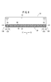
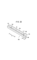
- FIG. 4 is a cross-sectional view taken along line IV-IV of FIG. 3; It is the top view which fractured
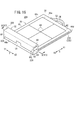
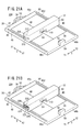
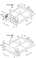
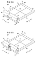
- 8A and 8B are perspective views illustrating the parallel movement of the control unit with respect to the panel unit.
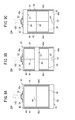
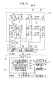
- FIG. 9A to 9C are plan views illustrating the transport state of the cassette. It is explanatory drawing which shows typically the arrangement of the pixel in a radiation conversion panel, and the electrical connection between a pixel and a cassette control part. It is a block diagram of the cassette of FIG. It is a flowchart for demonstrating imaging
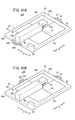
- FIG. 14A and FIG. 14B are perspective views illustrating a cassette provided to the buffer member in the control unit. 15A and 15B are cross-sectional views illustrating the parallel movement of the control unit with respect to the panel unit by the wheel. It is a perspective view of a cassette which provided the guide part in the side of a panel part.
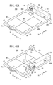
- FIG. 17 is a cross-sectional view taken along the line XVII-XVII in FIG. 18A and 18B are cross-sectional views illustrating the translation of the control unit with respect to the panel unit in the cassette of FIG. 19A and 19B are perspective views of a cassette in which two grips are provided on the panel.
- FIG. 20A and FIG. 20B are perspective views of a cassette in which the control unit and the panel unit are provided with the grips.
- FIG. 21A and FIG. 21B are perspective views of a cassette in which the control unit and the panel unit are provided with grips. It is a perspective view of a cassette which provided the holding part in the control part. It is a perspective view of a cassette which provided the rail-like guide part in the side of a panel part.
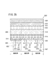
- FIG. 26 is a schematic configuration diagram of a TFT and a charge storage unit shown in FIG. 25. It is a block diagram of the radiographic imaging system to which the cassette which concerns on 2nd Embodiment is applied. It is a perspective view of the cassette of FIG. It is a perspective view of the cassette of FIG.
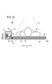
- FIG. 30 is a cross-sectional view of FIG. 29 taken along the line XXX-XXX. FIG. 30 is a cross-sectional view of FIG. 29 taken along the line XXXI-XXXI.
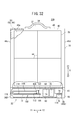
- FIG. 32 It is the top view which fractured
- 34A and 34B are plan views illustrating rotational movement of the control unit with respect to the panel unit.
- 35A and 35B are plan views illustrating the movement of the control unit with respect to the panel unit.
- 36A and 36B are perspective views illustrating rotational movement of the control unit with respect to the panel unit.
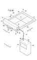
- 37A and 37B are plan views illustrating the transport state of the cassette. It is a perspective view which shows the state of the charge process with respect to a cassette.
- 39A and 39B are perspective views illustrating a cassette provided in the buffer member in the control unit.
- 40A and 40B are perspective views of a cassette in which the control unit and the panel unit are provided with the grips.
- 41A and 41B are perspective views of a cassette in which two grips are provided on the panel.
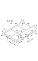
- 42A and 42B are perspective views of a cassette in which the control unit and the panel unit are provided with the grips.
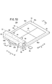
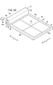
- FIGS. 43A and 43B are perspective views of a cassette in which the control unit and the panel unit are provided with the grips. It is a perspective view of the cassette which provided the holding part in the control part and the panel part, respectively.
- 45A and 45B are perspective views illustrating the rotation of the control unit with respect to the panel unit.
- 46A and 46B are enlarged plan views of the shaft portion, the protrusion portion, and the rotation restricting member of the cassette of FIGS.
- FIG. 45A and 45B It is a perspective view of a cassette which provided two holding parts in the control part. It is an expansion perspective view of the axial part of a cassette, a projection part, and a rotation control member.
- FIG. 49A is a perspective view of the cassette showing the case where the shaft portion is disposed at a different place from the case of FIG. 29 and FIG. 32
- FIG. 49B shows the movement of the control portion relative to the panel portion in the cassette of FIG.
- 50A is a perspective view illustrating the rotation of the control unit with respect to the panel unit in the cassette of FIG. 49B
- FIG. 50B is a perspective view illustrating the movement of the control unit with respect to the panel unit after the rotation of FIG. 50A.
- FIG. 53 is a perspective view of the cassette of FIG. 52.
- FIG. 53 is a perspective view of the cassette of FIG. 52.
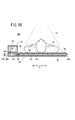
- FIG. 54 is a cross-sectional view along the line LV-LV in FIG. 53.
- FIG. 53 is a plan view showing a part of the cassette of FIG. 52 cut away. It is the top view which illustrated the conveyance state of the cassette of FIG. It is explanatory drawing which shows typically the arrangement of the pixel in a radiation conversion panel, and the electrical connection between a pixel and a cassette control part.
- FIG. 61A and 61B are perspective views of a cassette in which the control unit is provided with a grip. It is a block diagram of the radiographic imaging system which applied the cassette for double-sided imaging. It is a perspective view of the cassette of FIG. It is a perspective view of the cassette of FIG. FIG. 64 is a cross-sectional view of FIG. 63 taken along the line LXV-LXV. It is the top view which fractured
- a radiation imaging system 10A includes a radiation source 18 for irradiating a subject 14 such as a patient lying on an imaging table 12 such as a bed with a radiation 16 having a dose according to imaging conditions;
- the electronic cassette 20A detects the radiation 16 transmitted through the subject 14 and converts it into a radiation image, the console 22 controls the radiation source 18 and the electronic cassette 20A, and the display device 24 displays the radiation image.
- UWB Ultra Wide Band
- IEEE 802.11 Transmission and reception of signals are performed by wireless communication using a wireless LAN (Local Area Network) such as a / g / n or millimeter wave.
- a wireless LAN Local Area Network
- the signal may be transmitted and received by wired communication using a cable.
- a radiology information system (RIS) 26 that comprehensively manages radiation images and other information handled in the radiology department in the hospital is connected to the console 22.
- medical information in the hospital is provided in the RIS 26
- a medical information system (HIS) 28 that manages the entire content of the computer is connected.
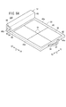
- the electronic cassette 20A as a radiation image capturing apparatus includes a panel unit 30 disposed between the imaging table 12 and the subject 14, a control unit 32 disposed on the panel unit 30, and a panel It is a portable electronic cassette provided with the holding part 34 arrange
- the thickness of the panel unit 30 is set to be thinner than the thickness of the control unit 32.
- the panel unit 30 has a substantially rectangular casing (first casing) 40 made of a material capable of transmitting the radiation 16, and the casing 40 on which the subject 14 lies.
- the upper surface of the is an irradiation surface 42 to which the radiation 16 is irradiated.
- a guide line 44 is formed which indicates the imaging region and the imaging position of the subject 14.
- the outer frame of the guide wire 44 becomes an imageable area 36 showing the radiation field of the radiation 16.
- the central position of the guide line 44 (the intersection of the two guide lines 44 intersecting in a cross shape) is the central position of the image captureable area 36 and the geometrical central position of the electronic cassette 20A. .
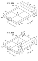
- a guide portion 48 formed of a linear recess or groove is along the arrow X direction (direction parallel to the side surfaces 46c and 46d).
- a guide portion 50 parallel to the guide portion 48 is formed along the arrow X direction on the side surface (the other side surface) 46 d side outside the imageable area 36.
- the linear guides 48 and 50 sandwich the imageable area 36 between the two side surfaces 46a and 46b (between the two sides of the irradiation surface 42). Are formed parallel to one another.
- a grip portion 34 is provided on the side surface 46a of the housing 40 (the other side surface), and between the handle portion of the grip portion 34 and the side surface 46a, a doctor or a technician (user) passes the hand. It is set as the hole 52 of a magnitude
- a projecting portion 54 that protrudes upward is provided, and the control unit 32 is on the side surface 46b side of the irradiation surface 42 so as to cover the projecting portion 54 from above. Is located in
- the control unit 32 has a substantially rectangular casing (second casing) 60 made of a material non-transparent to the radiation 16.
- the housing 60 extends along the arrow Y direction (a direction parallel to the side surfaces 46a and 46b) so as to cover a part of the guide portions 48 and 50 in the arrow X2 direction side (side surface 46b side) from above. (See Figure 5).
- the connector 64 which can be fitted to the connector (connecting portion) 62 provided on the side surface of the projecting portion 54 in the direction of the arrow X1, and the connector 64 electrically connected
- a cassette control unit (panel control unit) 66 that controls the panel unit 30 via 62 and 64, a power supply unit 68 such as a battery, and a communication unit 70 that can transmit and receive signals wirelessly between the console 22 and the like. It is arranged.
- the power supply unit 68 supplies power to the panel unit 30 via the connectors 62 and 64 while the power supply unit 68 supplies the cassette control unit 66 and the communication unit 70 with power. Also supply power.
- the power supply unit 68 supplies power only to the cassette control unit 66 when the connector 62 and the connector 64 are separated and the electrical connection between the panel unit 30 and the control unit 32 is cut off.
- the side surface 80 of the control unit 32 on the arrow Y 2 direction side (side surface 46 d side) is connected between the external adapter and the input terminal 82 of the AC adapter for charging the power supply unit 68 from the external power supply.
- a USB (Universal Serial Bus) terminal 84 as interface means capable of transmission and reception, and a card slot 88 for loading a memory card 86 such as a PC card are provided.
- a radiation conversion panel 92 for detecting the radiation 16 transmitted through 14 and a lead plate 94 for absorbing the back scattered radiation of the radiation 16 are disposed in order with respect to the irradiation surface 42 on the subject 14 side.
- the grid 90, the radiation conversion panel 92, and the lead plate 94 substantially coincide with the image captureable area 36 in plan view (see FIG. 5).
- the irradiation surface 42 may be configured as a grid 90.
- the radiation conversion panel 92 for example, a solid detection element (hereinafter referred to as a solid detection element (hereinafter referred to as “the radiation detection panel”) made of a material such as amorphous silicon (a-Si) Indirect conversion type radiation conversion panel which converts it into electric signal by the pixel), and direct conversion type which directly converts the dose of radiation 16 into electric signal by solid detection element which consists of substances such as amorphous selenium (a-Se) Radiation conversion panels can be employed.
- a-Si amorphous silicon
- a-Se amorphous selenium
- the radiation 16 transmitted through the subject 14 is once converted into visible light by, for example, a scintillator composed of cesium iodide (CsI) or gadolinium oxide sulfur (GOS), and the visible light is converted into a solid detection element Indirect conversion type radiation conversion panels (radiation detectors) which convert into electric signals by (pixels), there are a surface reading type radiation detector and a back side reading type radiation detector.
- the radiation detector of the ISS (Irradiation Side Sampling) method which is a surface reading method, has a configuration in which solid detection elements and a scintillator are arranged in order along the irradiation direction of the radiation 16.
- a radiation detector of the PSS (Penetration Side Sampling) method which is a back side reading method, has a configuration in which a scintillator and a solid detection element are arranged in order along the irradiation direction of the radiation 16.
- the radiation conversion panel 92 is electrically connected to the drive circuit unit 98 via the flexible substrate 96, and the drive circuit unit 98 is electrically connected to the connector 62 via the flexible substrate 100. It is connected.
- a recess 110 is formed on the side of the housing 60 in the direction of the arrow X2, and a connector 64 is provided in the recess 110.
- the cassette control unit 66 electrically connects with the drive circuit unit 98 through the connectors 64 and 62 and the flexible substrate 100.
- the drive circuit unit 98 drives and controls the radiation conversion panel 92 in accordance with a control signal (address signal) from the cassette control unit 66, reads a radiation image from the radiation conversion panel 92, and outputs the radiation image to the cassette control unit 66.
- the power supply unit 68 supplies power to the drive circuit unit 98 via the connectors 64 and 62 and the flexible substrate 100, thereby driving the radiation conversion panel 92 from the drive circuit unit 98 via the flexible substrate 96.
- FIG. 4 illustrates the case where the drive circuit unit 98 is disposed on the side of the panel unit 30 in the direction of the arrow X2.
- the drive circuit unit 98 is disposed on the side of the panel unit 30 in the direction of the arrow X2.
- other drive circuit units are actually disposed along the guide units 48 and 50, but in the first embodiment, the other drive circuit units are provided for ease of explanation. Illustration of is omitted.
- the bottoms of the guide portions 48 and 50 extending in the arrow X direction are formed as chambers 120 and 122 wider than the upper portions of the guide portions 48 and 50 communicating with the outside, as shown in FIG.
- the guide portion 48 includes a sliding portion 124 disposed in the chamber 120, and a connecting portion 126 which penetrates the guide portion 48 and connects the sliding portion 124 and the housing 60.
- a member 128 is provided.
- a moving member configured of a sliding portion 130 disposed in the chamber 122, and a connecting portion 132 which penetrates the guide portion 50 and connects the sliding portion 130 and the housing 60. 134 are provided.
- the width of the sliding portions 124 and 130 along the arrow Y direction substantially matches the width of the chambers 120 and 122 along the arrow Y direction, while the position of the upper surface of the sliding portions 124 and 130 is , And is positioned lower than the ceiling of the room 120, 122. That is, the chambers 120 and 122 are provided with clearances to such an extent that the sliding portions 124 and 130 can move up and down.
- the lengths of the sliding portions 124 and 130 and the coupling portions 126 and 132 along the arrow X direction are substantially the same length, and The length is set slightly shorter than the width along the X direction.
- the both ends along the arrow X direction of the sliding parts 124 and 130 are made into the slightly rounded shape which carried out the corner.
- a plurality of mountain-shaped convex portions (stop members) 140a to 140d are disposed at the bottom of the chambers 120 and 122 along the arrow X direction.
- the distance between the side surface 46a and the projection 140a, the distance between the projection 140b and the projection 140c, and the distance between the projection 140d and the side surface 46b are the sliding portions 124 and 130 and the connecting portion 126, respectively.
- the length is set to be substantially the same as the length along the arrow X direction of 132.
- the moving members 128 and 134 are connected to the bottom surface of the housing 60 of the control unit 32 and the moving members 128 and 134 are disposed in the guide portions 48 and 50, they are illustrated in FIGS. 7A to 8B.
- the movable members 128 and 134 slide in the arrow X direction integrally with the housing 60 while being guided by the guide portions 48 and 50.
- the plurality of convex portions 140a to 140d are disposed in the chambers 120 and 122 of the guide portions 48 and 50, but between the upper surfaces of the sliding portions 124 and 130 and the ceilings of the chambers 120 and 122.
- the moving members 128 and 134 move even if the sliding portions 124 and 130 abut the convex portions 140a to 140d. Can travel in the direction of arrow X over the protrusions 140a to 140d. Accordingly, the moving members 128 and 134 and the guide portions 48 and 50 constitute a moving mechanism 136 for parallelly moving the control unit 32 with respect to the panel unit 30 in the arrow X direction.
- the housing 60 of the control unit 32 is positioned on the side surface 46b side shown in FIGS. 3 and 7A.
- the housing 60 is positioned substantially at the center of the photographable area 36 shown in FIGS. 7B and 8A.
- the housing 60 is positioned on the side surface 46a and the gripping portion 34 shown in FIGS. 7C and 8B.
- FIGS. 9A to 9C illustrate transport of the electronic cassette 20A by the user 142 such as a doctor or a technician.
- the power supply unit 68 (see FIGS. 3 and 5) is relatively heavy, the ratio of the weight of the control unit 32 to the total weight of the electronic cassette 20A is large. Further, in the control unit 32, the cassette control unit 66, the power supply unit 68, and the communication unit 70 are centrally disposed in the central portion of the housing 60. Therefore, in the case of FIG. 9A, the geometric center position of the electronic cassette 20A (the center position of the recordable area 36) and the barycentric position (the position on the control unit 32 side) are eccentric. The overall load arrangement is unbalanced.
- the user 142 transports the electronic cassette 20A in a state where the control unit 32 is at the bottom and the center of gravity of the electronic cassette 20A is lowered, so even in an unbalanced load arrangement. , The electronic cassette 20A can be stably carried.
- the user 142 grips the gripping portion 34 to position the electronic cassette 20A with the control portion 32 disposed substantially at the center of the photographable area 36 and the gripping portion 34 at the top.
- the eccentric state is eliminated, and the load arrangement as a whole of the apparatus is balanced. As a result, the user 142 can stably carry the electronic cassette 20A.
- the geometrical center position of the electronic cassette 20A and the center-of-gravity position do not coincide with each other, and the load arrangement as a whole is unbalanced.
- the position of the center of gravity of the electronic cassette 20A is on the upper side, and the user 142 grips the control unit 32 having a large weight via the holding unit 34. Therefore, even in this case, the electronic cassette 20A is stably carried. be able to.
- the position of the housing 60 is on the side 46b side, the substantially central portion of the image captureable area 36, and the grip 34 and side 46a sides.
- the electronic cassette 20A can be reliably transported regardless of the position of the control unit 32 with respect to the panel unit 30 in any position of FIGS. 9A to 9C. .
- a large number of pixels 150 are arranged on a substrate (not shown), and these pixels 150 are further connected to the drive circuit 98 through the flexible substrate 96.
- a large number of gate lines 152 for supplying control signals and a large number of signal lines 154 for reading out electric signals output from the large number of pixels 150 and outputting the electric signals to the drive circuit unit 98 through the flexible substrate 96 are arranged.
- the radiation conversion panel 92 has a structure in which a photoelectric conversion layer in which each pixel 150 made of a material such as a-Si for converting visible light into an electric signal is formed on an array of matrix TFTs 156.
- a photoelectric conversion layer in which each pixel 150 made of a material such as a-Si for converting visible light into an electric signal is formed on an array of matrix TFTs 156.
- the TFT 156 connected to each pixel 150 is connected with a gate line 152 extending in parallel with the column direction and a signal line 154 extending in parallel with the row direction.
- Each gate line 152 is connected to the gate drive circuit 158, and each signal line 154 is connected to the multiplexer 170.
- a control signal for controlling on / off of the TFTs 156 arranged in the column direction is supplied from the gate drive circuit 158 to the gate line 152.
- the gate drive circuit 158 is supplied with an address signal from the cassette control unit 66.
- the multiplexer 170 is connected to the amplifier 164 via the sample and hold circuit 166.
- the multiplexer 170 includes an FET (field effect transistor) switch 168 that switches the signal line 154 and a multiplexer drive circuit 162 that outputs a selection signal to turn on one FET switch 168.
- An address signal is supplied from the cassette control unit 66 to the multiplexer drive circuit 162.
- An A / D converter 172 is connected to the FET switch 168, and a radiation image converted into a digital signal by the A / D converter 172 is supplied to a cassette control unit 66.
- the TFT 156 functioning as a switching element may be realized in combination with another imaging element such as a complementary metal-oxide semiconductor (CMOS) image sensor. Furthermore, it is possible to replace it with a CCD (Charge-Coupled Device) image sensor which transfers charges while shifting charges by a shift pulse corresponding to a gate signal in TFT.
- CMOS complementary metal-oxide semiconductor
- the cassette control unit 66 includes an address signal generation unit 180, an image memory 182, a cassette ID memory 184, and a connection state detection unit (connection detection unit) 186.
- the address signal generator 180 supplies an address signal to the gate drive circuit 158 and the multiplexer drive circuit 162.
- the image memory 182 stores the radiation image detected by the radiation conversion panel 92.
- the cassette ID memory 184 stores cassette ID information for specifying the electronic cassette 20A.
- the connection state detection unit 186 detects the presence or absence of an electrical connection state between the connector 62 and the connector 64, and controls the power supply from the power supply unit 68 to each unit in the electronic cassette 20A based on the detection result.
- the radiation imaging system 10A including the electronic cassette 20A according to the first embodiment is basically configured as described above. Next, the operation thereof will be described with reference to the flowchart of FIG.
- step S1 of FIG. 12 the user 142 who is a doctor or a technician holds the gripping portion 34 with the gripping portion 34 at the top and the control portion 32 disposed at a substantially central portion of the imageable area 36. Then, the electronic cassette 20A is transported from a predetermined storage place such as a radiology department in a hospital to the imaging table 12 (see FIG. 1) (see FIG. 9B). In this case, since the connector 62 and the connector 64 are not fitted, the connection state detection unit 186 (see FIG. 11) detects that the electrical connection between the connector 62 and the connector 64 is interrupted. The power supply unit 68 is controlled to supply power only to the cassette control unit 66. As a result, the electronic cassette 20A enters the sleep state in which only the cassette control unit 66 is operating.
- a predetermined storage place such as a radiology department in a hospital
- the connection state detection unit 186 detects that the electrical connection between the connector 62 and the connector 64 is interrupted.
- the power supply unit 68 is controlled to supply power
- the user 142 arranges the electronic cassette 20A on the photographing table 12 with the control unit 32 and the irradiation surface 42 directed upward, and then the position of the housing 60 of the control unit 32 can be photographed It translates from the position of the approximately central portion 36 (see FIGS. 7B and 8A) to the position on the side 46b (see FIGS. 1 to 5 and 7A).
- the moving members 128 and 134 slide integrally with the housing 60 in the arrow X2 direction, and the sliding portions 124 and 130 move to the convex portion 140d. Even if they abut each other, they move over the protrusions 140d and further slide in the direction of the arrow X2.
- the moving members 128 and 134 are positioned between the side surface 46 b and the convex portion 140 d. That is, the housing 60 of the control unit 32 connected to the moving members 128 and 134 is positioned on the side surface 46 b side, and the connector 62 of the protrusion 54 and the connector 64 of the recess 110 are engaged.
- connection state detection unit 186 When the connection state detection unit 186 detects that the connector 62 and the connector 64 are electrically connected by fitting the connector 62 and the connector 64, the connection state detection unit 186 transmits a cassette control unit 66 to the power supply unit 68. In addition, control is performed to supply power to the communication unit 70 and the panel unit 30 as well. As a result, the power supply unit 68 starts supplying power to the communication unit 70 and the panel unit 30, so that the communication unit 70 can transmit and receive signals wirelessly to and from the console 22. In addition, the drive circuit unit 98 of the panel unit 30 is activated by the power supply from the power supply unit 68, and the bias circuit 160 supplies a bias voltage to each pixel 150 to enable charge accumulation of each pixel 150. Bring to the end. As a result, the electronic cassette 20A shifts from the sleep state to the active state.
- the user 142 prepares for imaging a radiographic image of the imaging region of the subject 14.
- the user 142 operates the console 22 to set imaging conditions such as subject information related to the subject 14 to be imaged (for example, the tube voltage or tube current of the radiation source 18 and the radiation time of the radiation 16). Register When the region to be imaged and the imaging method are determined in advance, the user 142 also registers these imaging conditions.
- subject information related to the subject 14 to be imaged for example, the tube voltage or tube current of the radiation source 18 and the radiation time of the radiation 16.
- the user 142 adjusts the inter-imaging distance between the radiation source 18 and the radiation conversion panel 92 to SID (inter-source-image distance), and places the subject 14 on the irradiation surface 42,
- SID inter-source-image distance
- the subject 14 is positioned (positioned) such that the imaging region of the subject 14 enters the imaging available area 36 and the center position of the imaging site substantially coincides with the center position of the imaging available area 36.
- step S4 after the preparation for imaging is completed, the user 142 turns on an exposure switch (not shown) provided on the console 22 or the radiation source 18.
- an exposure switch (not shown) provided on the console 22 or the radiation source 18.
- imaging conditions are transmitted from the console 22 to the radiation source 18 by wireless communication.
- the radiation source 18 is provided with an exposure switch, transmission of imaging conditions is requested from the radiation source 18 to the console 22 by wireless communication after the exposure switch is turned on.
- the imaging conditions are transmitted to the radiation source 18 by wireless communication.
- the radiation source 18 When receiving the imaging condition, the radiation source 18 irradiates the object 14 with a radiation 16 having a predetermined dose for a predetermined exposure time according to the imaging condition.
- the radiation 16 passes through the subject 14 and reaches the radiation conversion panel 92 in the panel unit 30.
- step S5 when the radiation conversion panel 92 is an indirect conversion type radiation conversion panel, the scintillator constituting the radiation conversion panel 92 emits visible light of an intensity corresponding to the intensity of the radiation 16, and the photoelectric conversion layer Each of the pixels 150 that make up the pixel converts visible light into an electrical signal and stores it as a charge. Then, charge information which is a radiation image of the subject 14 held in each pixel 150 is read out according to the address signal supplied from the address signal generation unit 180 constituting the cassette control unit 66 to the gate drive circuit 158 and the multiplexer drive circuit 162.
- the gate drive circuit 158 supplies a control signal to the gate of the TFT 156 connected to the gate line 152 corresponding to the address signal supplied from the address signal generator 180.
- the multiplexer drive circuit 162 outputs a selection signal according to the address signal supplied from the address signal generation unit 180 to sequentially switch the FET switches 168 (turn on and off sequentially), and the gate line selected by the gate drive circuit 158 A radiation image as charge information held in each pixel 150 connected to 152 is sequentially read out via the signal line 154.
- the radiation image read out from each pixel 150 connected to the selected gate line 152 is amplified by each amplifier 164 and then sampled by each sample and hold circuit 166 and A / D converted via the FET switch 168 It is supplied to the unit 172 and converted into a digital signal.
- the radiation image converted into the digital signal is temporarily stored in the image memory 182 of the cassette control unit 66 (step S6).
- the gate drive circuit 158 sequentially switches the gate lines 152 outputting the control signal according to the address signal supplied from the address signal generation unit 180, and is held in each pixel 150 connected to each gate line 152.
- the radiation image which is the charge information, is read out through the signal line 154 and stored in the image memory 182 of the cassette control unit 66 through the FET switch 168 and the A / D converter 172 (step S6).
- the radiation image stored in the image memory 182 is transmitted to the console 22 by wireless communication via the communication unit 70 together with the cassette ID information stored in the cassette ID memory 184.
- the console 22 performs predetermined image processing on the received radiation image, and transmits the radiation image after the image processing to the display device 24 by wireless communication.
- the display 24 displays the received radiation image (step S7).
- the user 142 visually recognizes the radiation image displayed on the display device 24 to confirm that the radiation image of the appropriate subject 14 has been obtained, and in step S8 after the imaging of the subject 14 is completed, the user 142 From the current position on the side 46b (see FIGS. 1 to 5 and 7A) to the position of the substantially central portion of the image captureable area 36 (see FIGS. 7B and 8A). Move up to parallel.
- the user 142 pushes the housing 60 in the arrow X1 direction, and the moving members 128 and 134 connected to the control unit 32 are guided by the guide portions 48 and 50 in the arrow X1 direction. Slide together (translate).
- connection state detection unit 186 When the connection state detection unit 186 detects that the electrical connection between the connector 62 and the connector 64 is interrupted, the connection state detection unit 186 controls the power supply unit 68 to supply power only to the cassette control unit 66. Thereby, the power supply unit 68 immediately stops the power supply to the communication unit 70 and the panel unit 30, and supplies the power only to the cassette control unit 66. As a result, the electronic cassette 20A shifts from the active state to a sleep state where only the cassette control unit 66 can operate.
- the moving members 128 and 134 move in parallel in the arrow X1 direction integrally with the housing 60, and the sliding portions 124 and 130 are convex. Even if they abut on the portions 140c, they move over the protrusions 140c and move in parallel in the direction of the arrow X1.
- the moving members 128 and 134 are positioned between the convex part 140 c and the convex part 140 b.
- the housing 60 of the control unit 32 connected to the position 134 is positioned substantially at the center of the imageable area 36.
- step S9 the user 142 grips the electronic cassette 20A by holding the gripping portion 34 with the gripping portion 34 as the uppermost portion and the control portion 32 disposed at the substantially central portion of the photographable area 36. Transport to a designated storage place such as a radiology department in a hospital.
- the control unit 32 causing the unbalanced load arrangement is configured by the guide portions 48 and 50 and the moving members 128 and 134.
- the moving mechanism 136 By moving the panel unit 30 in parallel along the arrow X direction using the moving mechanism 136, it is possible to easily change the position of the center of gravity of the electronic cassette 20A.
- the control unit 32 since the ratio of the weight of the control unit 32 to the total weight of the electronic cassette 20A is relatively large, the control unit with respect to the central position of the geometric shape of the electronic cassette 20A (substantially central portion of the photographable area 36) If the position of the electronic cassette 20A is shifted, the center of gravity of the electronic cassette 20A does not coincide with the center position and becomes eccentric, resulting in an unbalanced load arrangement as a whole of the apparatus.
- control unit 32 is moved in parallel along the arrow X direction with respect to the panel unit 30 so that the center position and the center-of-gravity position substantially coincide with each other to achieve unbalanced load arrangement. It can be eliminated easily.
- the guide portion 48, 50 and the moving members 128, 134 are used to move the position of the control portion 32 relative to the panel portion 30 to a position substantially at the center of the image captureable area 36 shown in FIGS. 7B and 8A. After the parallel movement, as shown in FIG. 9B, the electronic cassette 20A is transported with the gripping portion 34 at the top.
- the user 142 feels light on the electronic cassette 20A at the time of transportation, so that the electronic cassette 20A can be carried stably and easily.
- the electronic cassette 20A can be transported without hitting the control unit 32 against any object or dropping the electronic cassette 20A, and the burden on the user 142 during transportation is also reduced. Ru.
- the unbalanced load arrangement in the electronic cassette 20A can be easily eliminated.
- the user 142 can stably carry the electronic cassette 20A during transportation.
- the moving members 128 and 134 and the control unit 32 integrally and linearly move in parallel along the arrow X direction along the guide units 48 and 50, the control unit with respect to the panel unit 30 by a simple mechanism 32 can be translated.
- the control unit 32 can be retracted from the image captureable area 36 at the time of image capture. There is no problem in taking radiographs.
- the guide portions 48, 50 are formed along the arrow X direction (longitudinal direction of the housing 40) substantially perpendicular to the two sides (side surfaces 46a, 46b) of the irradiation surface 42.
- the control unit 32 has two moving members 128. , 134 are attached, and the two moving members 128, 134 are respectively disposed in the two guide portions 48, 50.
- the control unit 32 and the two moving members 128 and 134 can be translated more stably and reliably along the two guide units 48 and 50.
- the guide portions 48 and 50 are recesses or grooves formed substantially linearly on the irradiation surface 42 of the housing 40, and the moving members 128 and 134 can slide linearly along the inside of the recesses or grooves. Because of this, the control unit 32 can be simply and reliably translated relative to the panel unit 30.
- the control unit 32 can be reliably stopped at an arbitrary position.
- the side surface 46a of the panel unit 30 is provided with the gripping portion 34 for the user 142 to grip and transport the electronic cassette 20A, so the electronic cassette 20A can be easily carried.
- the power supply unit 68 stops the power supply to the communication unit 70 and the panel unit 30, thereby suppressing unnecessary power consumption.
- the cassette control unit 66 includes a connection state detection unit 186 that detects the presence or absence of an electrical connection between the connectors 62 and 64.
- the connection state detection unit 186 indicates the presence or absence of an electrical connection between the connectors 62 and 64. By detecting this, it is possible to easily grasp the timing of control on the panel unit 30 and the timing of reading out a radiation image on the radiation conversion panel 92. Further, by notifying the detection result from the connection state detection unit 186 to the power supply unit 68, it is also possible to realize efficient power supply.
- the thickness of the panel section 30 thinner than the thickness of the control section 32, it is possible to realize the thickness reduction and weight reduction of the electronic cassette 20A.
- the control unit 32 can be moved in parallel in the arrow X direction using the moving mechanism 136 including the guide portions 48 and 50 and the moving members 128 and 134, After the control unit 32 is moved to the position shown in FIGS. 3 and 7A with respect to the panel unit 30, as shown in FIG. 9A, the gripping unit 34 is the top and the control unit 32 is the bottom. In the state, it is also possible to transport the electronic cassette 20A.
- the electronic cassette 20A is transported with the center of gravity of the electronic cassette 20A lowered, so that the electronic cassette 20A can be stably carried.
- the electronic cassette 20A can be stably and easily It is possible to carry Therefore, even in the case of FIG. 9A, the electronic cassette 20A can be transported without hitting the control unit 32 against an arbitrary object or dropping the electronic cassette 20A, and the user 142 at the time of transportation can be transported. Burden is also reduced.
- the gripping unit 34 and the control unit 32 are uppermost. It is also possible to transport the electronic cassette 20A in the state described above.
- the user 142 holds the heavy control unit 32 via the holding unit 34, so the electronic cassette 20A can be stably carried.
- the electronic cassette 20A can be stably and easily It is possible to carry Therefore, even in the case of FIG. 9C, the electronic cassette 20A can be transported without hitting the control unit 32 against an arbitrary object or dropping the electronic cassette 20A, and the user 142 at the time of transportation can be transported. Burden is also reduced.
- the case where the case 60 of the control unit 32 which is thicker than the case 40 of the panel unit 30 is disposed on the case 40 has been described, but the description is limited to this Instead, as long as the control unit 32 can move in parallel with respect to the panel unit 30, the control unit 32 may be provided in a state of protruding from the housing 40.
- the control unit 32 is disposed at a location other than the shootable area 36 in the panel unit 30.
- the first embodiment is not limited to the above description, and in the panel unit 30, the control unit 32 may be disposed at a place other than the area to which the radiation 16 transmitted through the subject 14 is irradiated.
- the control unit 32 can be disposed at a position in the imageable area 36 where the radiation 16 is not irradiated.
- the console 22 can obtain a desired image corresponding to the small area by trimming a portion corresponding to the portion irradiated with the radiation 16 in the radiation image acquired from the electronic cassette 20A.
- the electronic cassette 20A according to the first embodiment is not limited to the above description, and the embodiments shown in FIGS. 13 to 26 can also be realized.
- FIG. 13 is a perspective view showing the charging process of the power supply unit 68 by the cradle 190 disposed at a necessary place in the medical institution.
- the electronic cassette 20A and the cradle 190 are electrically connected by the USB cable 192 having the connectors 194 and 196.
- the cradle 190 performs transmission and reception of necessary information with the console 22 and the RIS 26 in the medical institution using not only the charging of the power source unit 68 but also the wireless communication function or the wired communication function of the cradle 190. Good.
- the information to be transmitted and received can include a radiation image recorded in the image memory 182 of the electronic cassette 20A.
- the display unit 198 may be disposed on the cradle 190, and the display unit 198 may display the charge state of the electronic cassette 20A and necessary information including a radiation image acquired from the electronic cassette 20A. .
- a plurality of cradles 190 can be connected to the network, and the charge states of the electronic cassettes 20A connected to the cradles 190 can be collected via the network to confirm the whereabouts of the electronic cassettes 20A in the usable charge state. It can also be configured.
- FIG. 14A illustrates the case where the housing 60 of the control unit 32 is entirely covered by the buffer member 200
- FIG. 14B illustrates the case where the side surface 46b side of the housing 60 is covered by the buffer member 202. It is
- the control unit 32 When the electronic cassette 20A is transported in a state where the control unit 32 is disposed on the side surface 46b with respect to the panel unit 30, as shown in FIG. 9A, the control unit 32 is disposed at the bottom of the electronic cassette 20A. Therefore, by providing the buffer member 200 entirely covering the casing 60 of the control unit 32 or the buffer member 202 partially covering, the case where the control unit 32 is hit against another object or the electronic cassette 20A can be obtained. It is possible to effectively protect the control unit 32 from the impact when dropped.
- 15A and 15B illustrate a case where the control unit 32 is translated in the arrow X direction by the moving member 208 using the wheel 210, instead of the moving members 128 and 134 in FIGS. 6 to 7C.
- the moving mechanism 136 is configured by the moving member 208 and the guide portions 48 and 50.
- the moving member 208 disposed in each of the guide portions 48 and 50 has four wheels 210 capable of traveling at the bottom of the chambers 120 and 122, an axle 212 of the four wheels 210 penetrating, and along the arrow X direction. It has a chassis 214 extending and a connecting portion 216 for connecting the chassis 214 and the case 60 of the control unit 32.
- the total length (the distance from the wheel 210 on the arrow X1 direction side to the wheel 210 on the arrow X2 direction side) along the arrow X direction of each moving member 208 substantially matches the distance between the side surface 46b and the convex portion 140d. ing.
- clearances are provided to the extent that the wheels 210 move up and down.
- 16 to 18B illustrate the case where the guide portions 220 and 222 are formed on the side surfaces 46c and 46d.
- the guide portions 220 and 222 are arranged parallel to each other along the direction of the arrow X between the side surface 46 a and the side surface 46 b, similarly to the guide portions 48 and 50 (see FIGS. 2, 3, 5 and 6) It is set up.
- a protrusion 226 extending downward along the side surface 46 d is formed on the side surface 80 side of the housing 60 of the control unit 32, and on the other side surface 308 side, the protrusion 26 extends downward along the side surface 46 c.
- a protruding portion 224 is formed to extend to the end. Accordingly, the protrusions 224 and 226 are disposed so as to cover a part of the side surfaces 46 b of the guide portions 220 and 222 (see FIGS. 16 and 17).
- the radiation conversion panel 92 side of the guide portions 220 and 222 is formed as a chamber 230 or 232 having a wider width in the vertical direction as compared with the inlet side communicating with the outside.
- moving members 238 and 244 having substantially the same shape as the moving members 128 and 134 (see FIGS. 6 to 7C).
- Moving members 258, 264 which can travel by the wheels 254, 260 are disposed in a state of being connected to the projecting portions 224, 226 of the housing 60. Therefore, the moving mechanism 136 is configured by the moving members 238, 244, 258, 264 and the guide portions 220, 222.
- the moving members 238 and 244 include sliding portions 234 and 240 disposed in the chambers 230 and 232, and coupling portions 236 and 242 for coupling the sliding portions 234 and 240 and the projecting portions 224 and 226.
- the moving members 258, 264 also have two wheels 254, 260 disposed in the chambers 230, 232, respectively, and axles 256, 262 connecting the wheels 254, 260 and the protrusions 224, 226, respectively.
- the total length of the moving members 238, 244, 258, 264 in the direction of the arrow X is substantially the same as the distance between the side surface 46 b and the convex portion 270. Also, between the sliding portions 234 and 240 and the wheels 254 and 260 and the ceiling of the chamber 230 and 232, a clearance is provided to the extent that the sliding portions 234 and 240 and the wheels 254 and 260 move up and down. .
- the moving members 238, 244, 258, and 264 guide the guide portion. While being guided by 220 and 222, they move in parallel in the arrow X direction integrally with the housing 60. Also, between the sliding portions 234 and 240 and the wheels 254 and 260 and the ceiling of the chamber 230 and 232, a clearance is provided to the extent that the sliding portions 234 and 240 and the wheels 254 and 260 move up and down.
- control unit 32 can be simply and reliably translated in the arrow X direction with respect to the panel unit 30.
- FIGS. 19A to 22 each show the case where the grips are disposed at places other than the side surface 46a.
- FIG. 19A shows that the gripping portion 280 is disposed on the side surface 46 b side of the projecting portion 54 in addition to the gripping portion 34, and the user 142 takes a hand between the handle portion of the gripping portion 280 and the projecting portion 54.
- the hole 282 is of a size that allows passage of
- the user 142 holds the grip 34 with one hand while the control unit 32 is moved parallel to the position of FIGS. 7B and 8A with respect to the panel 30, for example.
- the electronic cassette 20A may be transported by gripping the grip portion 280.
- the electronic cassette 20A can be transported in a well-balanced load arrangement, and the electronic cassette 20A can be transported with both hands, so that the stability when carrying can be further enhanced.
- the two gripping portions 34 and 280 are disposed, in addition to the transport in a state in which the gripping portion 34 is gripped (see FIGS. 9A to 9C), the electronic cassette with the gripping portion 280 at the top It will also be possible to transport 20A, improving the ease of use during transport.
- FIG. 19B shows that the grip portion 330 is disposed on the side surface 46 c side in addition to the grip portion 34, and the size of the user 142 can pass the hand between the handle portion of the grip portion 330 and the side surface 46 c.
- the user 142 holds the grip portion 330 as the uppermost portion in a state in which the control portion 32 is moved parallel to the position of FIGS. 7B and 8A with respect to the panel portion 30, for example, and transports the electronic cassette 20A. do it. Even in this case, the electronic cassette 20A can be stably transported since the load arrangement state is well balanced. In addition, since the two grips 34 and 330 are disposed, the ease of transportation is improved as in the case of FIG. 19A.
- the gripping portion 290 is disposed also on the upper surface of the housing 60 of the control portion 32, and between the handle portion of the gripping portion 290 and the upper surface of the housing 60 A hole 292 is large enough to pass a hand.
- the user 142 may carry the electronic cassette 20A by holding the grip portion 290 as the top, for example, with the control portion 32 arranged at the position of FIG. 20A with respect to the panel portion 30.
- the electronic cassette 20A can be transported in a well-balanced load arrangement, and the heavy control unit 32 is directly gripped through the grip portion 290. Therefore, when the electronic cassette 20A is carried, the electronic cassette 20A can be It is possible to feel light and carry the electronic cassette 20A stably and easily.
- control unit 32 when the control unit 32 is moved in parallel with respect to the panel unit 30, the control unit 32 may be moved in parallel while gripping the holding unit 290. Therefore, the parallel movement can be easily performed.
- FIG. 20B is different from the case of FIG. 20A in that a foldable grip portion 300 is provided on the upper surface of the housing 60.
- a substantially hexagonal recess 302 is formed on the top surface of the housing 60, and both ends of the grip 300 are disposed in the recess 302. Further, in the recess 302, a rectangular support portion 304 is disposed, and both end portions of the shaft portion 306 penetrating the support portion 304 are connected to both end portions of the grip portion 300.
- the grip portion 300 When the user 142 does not grip the grip portion 300, the grip portion 300 is accommodated in the recess 302. On the other hand, when gripping the grip portion 300, the user 142 pulls out and grips the grip portion 300 from the recess 302 while rotating the central portion of the grip portion 300 around the shaft portion 306. Further, when the grip portion 300 is accommodated in the recess portion 302, the central portion of the grip portion 300 may be pivoted to the recess portion 302 centering on the shaft portion 306.
- the presence of the gripping portion 300 is an obstacle to the imaging of the subject 14 because the gripping portion 300 only needs to be pulled out during transportation or parallel movement of the control portion 32.
- the usability of the electronic cassette 20A is further improved.
- FIG. 21A differs from the case of FIG. 20A in that the grip portion 310 is disposed on the side surface 308 of the housing 60. In this case, a hole 312 is formed between the handle portion of the grip portion 310 and the side surface 308 of the housing 60 so that the user 142 can pass the hand.
- FIG. 21B is different from the case of FIG. 20B in that a foldable grip portion 320 is disposed on the side surface 308 of the housing 60.
- a substantially hexagonal recess 322 is formed on the side surface 308 of the housing 60, and both ends of the grip 320 are disposed in the recess 322.
- a rectangular support portion 324 is disposed in the concave portion 322, and both end portions of the shaft portion 326 penetrating the support portion 324 are connected to both end portions of the grip portion 320.
- FIG. 22 illustrates the case where a foldable grip portion 410 is provided on the side surface 46 a side of the housing 60 instead of the grip portion 34 of the side surface 46 a.
- a substantially hexagonal recess 412 is formed on the side surface 46 a side of the housing 60, and both ends of the grip 410 are disposed in the recess 412.
- a rectangular support portion 414 is disposed in the recess portion 412, and both end portions of the shaft portion 416 penetrating the support portion 414 are connected to both end portions of the grip portion 410.
- the user 142 directly grips the heavy control unit 32 via the grip unit 410, so when carrying the electronic cassette 20A.
- the electronic cassette 20A can be felt lightly, and the electronic cassette 20A can be carried stably and easily.
- the holding portion 410 since the holding portion 410 is of the foldable type, the holding portion 410 may be pulled out only when carrying or translating the control portion 32. Therefore, the presence of the holding portion 410 does not interfere with photographing of the subject 14. The usability of the electronic cassette 20A is improved.
- FIGS. 23 and 24 can also be adopted as the electronic cassette 20A according to the first embodiment.
- FIG. 23 illustrates the case where rail-shaped guide portions 500 and 502 are formed on the side surfaces 46c and 46d, respectively, instead of the guide portions 220 and 222 described above. Further, in the guide portions 500 and 502, a plurality of mountain shaped convex portions 506a to 506d having the same function as the convex portions 140a to 140d and 270 described above are disposed. Furthermore, on the side surface 46 b side of the irradiation surface 42, a protruding portion 504 having the same function as the above-described protruding portion 54 is detachably disposed with respect to the housing 40. Note that, in FIG. 23, the protruding portions 224 and 226 are configured as moving members (sliding portions) that slide along the guide portions 500 and 502.
- control unit 32 can be removed from the panel unit 30 by sliding the control unit 32 in the direction of the arrow X2 along the guide units 500 and 502 in a state where the protrusion 504 is removed from the housing 40. It becomes. As a result, maintenance and parts replacement of the electronic cassette 20A become easy.
- the projection portion 504 is disposed instead of the projection portion 54, thereby the projection portion
- the irradiation surface 42 is irradiated with the radiation 16
- the electronic cassette 20A for double-sided imaging is used as shown in FIG.
- the subject 14 can also be photographed after being arranged on the photographing table 12.
- the bottom side of the panel unit 30 is the imaging surface to which the radiation 16 is irradiated, and the grid 90 and the lead plate 94 are omitted.
- the same effects as those of the embodiments described above can be obtained, and the irradiation surface 42 or the bottom surface can be selected as the photographing surface according to the photographing method for the subject 14. Further improve.
- the first embodiment can also be applied to the case of acquiring a radiation image using a light conversion type radiation conversion panel.
- the light reading type radiation conversion panel when radiation is incident on each solid detection element, an electrostatic latent image corresponding to the dose is accumulated and recorded on the solid detection element.
- the radiation conversion panel When reading the electrostatic latent image, the radiation conversion panel is irradiated with the reading light, and the value of the generated current is acquired as a radiation image.
- the radiation conversion panel can erase and reuse the radiation image, which is the remaining electrostatic latent image, by irradiating the radiation conversion panel with the erasing light (see JP-A-2000-105297).
- the entire device in order to prevent the possibility of blood or other miscellaneous bacteria to adhere, for example, the entire device is made waterproof and airtight, and may be sterilized and cleaned as necessary.
- the electronic cassette 20A can be used repeatedly and continuously.
- the first embodiment is not limited to radiographing in a medical institution, and may be installed in a disaster site, a home nursing home, or a medical examination car, and may be applied to radiographing a subject in a health checkup. Is possible. Furthermore, the first embodiment is not limited to the radiographing of medical-related radiation images as described above, and is naturally applicable to radiographing of radiographs in various nondestructive inspections, for example.
- the first invention is, of course, not limited to the above-described embodiment, and various configurations can be adopted without departing from the scope of the first invention.
- the radiation conversion panel 92 may be a radiation detector 600 according to the modification shown in FIG. 25 and FIG. FIG. 25 is a schematic cross-sectional view schematically showing the configuration of three pixel portions of a radiation detector 600 according to a modification.
- the radiation detector 600 is formed by sequentially laminating a signal output unit 604 including a switching element, a sensor unit 606 including a solid detection element, and a scintillator 608 on an insulating substrate 602.
- the sensor unit 606 constitutes a pixel unit.
- the pixel units are arranged in a matrix on the substrate 602, and the signal output units 604 and the sensor units 606 in each pixel unit are configured to have an overlap.
- the scintillator 608 is formed on the sensor unit 606 via the transparent insulating film 610, and is formed by depositing a phosphor that converts the radiation 16 into light and emits light.
- the upper side (the side opposite to the side on which the substrate 602 is located) is the irradiation surface 42 (FIGS. 2 to 5, 8A to 9C, 13 to 14B, 16 and 19A to When the radiation 16 is incident from the upper side in the case of the side shown in FIG. 23), the radiation detector 600 functions as a PSS type radiation detector, and the phosphor of the scintillator 608 converts the incident radiation 16 into light. Convert and emit light.
- the wavelength range of light emitted by the scintillator 608 is preferably a visible light range (wavelength 360 nm to 830 nm), and in order to enable monochrome imaging by the radiation detector 600, it includes a green wavelength range. Is more preferred.
- CsI (Tl) having an emission spectrum at 420 nm to 700 nm at the time of X-ray irradiation It is particularly preferable to use (cesium iodide to which thallium is added).
- the emission peak wavelength of CsI (Tl) in the visible light range is 565 nm.
- the scintillator 608 may be formed, for example, by vapor depositing CsI (Tl) of a columnar crystal structure on a vapor deposition substrate.
- CsI CsI
- the vapor-deposited substrate is often made of Al in terms of X-ray transmittance and cost, but is not limited thereto.
- GOS may be applied to a resin base and then bonded to the surface of the TFT active matrix substrate. Thereby, even if the application of GOS fails, the TFT active matrix substrate can be preserved.
- the sensor unit 606 includes an upper electrode 612, a lower electrode 614, and a photoelectric conversion film 616 disposed between the upper electrode 612 and the lower electrode 614.
- the upper electrode 612 is preferably made of a conductive material transparent to at least the light emission wavelength of the scintillator 608 because the light generated by the scintillator 608 needs to be incident on the photoelectric conversion film 616. Specifically, It is preferable to use a transparent conductive oxide (TCO) having a high transmittance to visible light and a small resistance value. Although a metal thin film of Au or the like can be used as the upper electrode 612, TCO is more preferable because the resistance value tends to increase if it is intended to obtain a transmittance of 90% or more.
- TCO transparent conductive oxide
- ITO Indium Tin Oxide
- IZO Indium Tin Oxide
- AZO Zinc Oxide
- FTO Zinc Oxide
- SnO 2 Tin Oxide
- TiO 2 TiO 2
- ZnO 2 Zinc Oxide
- the upper electrode 612 may have a single-plate configuration common to all pixel portions, or may be divided for each pixel portion.
- the photoelectric conversion film 616 includes an organic photo conductor (OPC), absorbs light emitted from the scintillator 608, and generates a charge according to the absorbed light.
- OPC organic photo conductor
- a photoelectric conversion film 616 containing an organic photoconductor (organic photoelectric conversion material) has a sharp absorption spectrum in the visible light range, and almost all electromagnetic waves other than that emitted by the scintillator 608 are absorbed by the photoelectric conversion film 616 Instead, noise generated by the radiation 16 absorbed by the photoelectric conversion film 616 can be effectively suppressed.
- the photoelectric conversion film 616 may be configured to contain a-Si instead of the organic photoconductor. In this case, it has a wide absorption spectrum, and the light emitted by the scintillator 608 can be efficiently absorbed.
- the peak wavelength of the organic photoconductor constituting the photoelectric conversion film 616 is closer to the light emission peak wavelength of the scintillator 608 in order to absorb the light emitted by the scintillator 608 most efficiently.
- the absorption peak wavelength of the organic photoconductor and the emission peak wavelength of the scintillator 608 match, but if the difference between the two is small, it is possible to sufficiently absorb the light emitted from the scintillator 608.
- the difference between the absorption peak wavelength of the organic photoconductor and the emission peak wavelength of the scintillator 608 with respect to the radiation 16 is preferably 10 nm or less, and more preferably 5 nm or less.
- organic photoconductors that can satisfy such conditions include quinacridone organic compounds and phthalocyanine organic compounds.
- quinacridone organic compounds since the absorption peak wavelength of quinacridone in the visible region is 560 nm, if using quinacridone as the organic photoconductor and CsI (Tl) as the material of the scintillator 608, the difference between the above peak wavelengths can be 5 nm or less. As a result, the amount of charge generated in the photoelectric conversion film 616 can be substantially maximized.
- the sensor unit 606 is a stack of an electromagnetic wave absorbing site, a photoelectric conversion site, an electron transporting site, a hole transporting site, an electron blocking site, an electron blocking site, a crystallization blocking site, an electrode, an interlayer contact improving site, etc. It comprises comprising the organic layer formed by mixing.
- the organic layer preferably contains an organic p-type compound (organic p-type semiconductor) or an organic n-type compound (organic n-type semiconductor).
- the organic p-type semiconductor is a donor type organic semiconductor (compound) mainly represented by a hole transporting organic compound, and refers to an organic compound having a property of easily giving an electron. More specifically, it refers to an organic compound having a smaller ionization potential when used in contact with two organic materials. Therefore, any organic compound can be used as the donor organic compound, as long as it is an electron-donating organic compound.
- the organic n-type semiconductor is an acceptor type organic semiconductor (compound) mainly represented by an electron transporting organic compound, and refers to an organic compound having a property of easily accepting an electron.
- an acceptor type organic semiconductor compound mainly represented by an electron transporting organic compound
- the organic compound having larger electron affinity is used. Therefore, as the acceptor-type organic compound, any organic compound can be used as long as it is an electron-accepting organic compound.
- the materials applicable as the organic p-type semiconductor and the organic n-type semiconductor, and the configuration of the photoelectric conversion film 616 are described in detail in JP 2009-32854 A, and thus the description thereof is omitted.
- the photoelectric conversion film 616 may further be formed by containing fullerene or carbon nanotube.
- the thickness of the photoelectric conversion film 616 is preferably as large as possible from the point of absorbing light from the scintillator 608, but if it becomes thicker than a certain degree, it is generated in the photoelectric conversion film 616 by the bias voltage applied from both ends of the photoelectric conversion film 616.
- the intensity of the electric field decreases to make it impossible to collect charges, so 30 nm to 300 nm is preferable, more preferably 50 nm to 250 nm, and particularly preferably 80 nm to 200 nm.
- the photoelectric conversion film 616 has a common single sheet structure in all the pixel units, but may be divided for each pixel unit.
- the lower electrode 614 is a thin film divided for each pixel portion. However, the lower electrode 614 may have a common single-plate configuration in all pixel portions.
- the lower electrode 614 can be made of a transparent or opaque conductive material, and Al, silver or the like can be suitably used.
- the thickness of the lower electrode 614 can be, for example, 30 nm or more and 300 nm or less.
- one of the charges (holes and electrons) generated in the photoelectric conversion film 616 is moved to the upper electrode 612 by applying a predetermined bias voltage between the upper electrode 612 and the lower electrode 614. And move the other to the lower electrode 614.
- a wire is connected to the upper electrode 612, and a bias voltage is applied to the upper electrode 612 through the wire. Further, it is assumed that the bias voltage is determined such that electrons generated in the photoelectric conversion film 616 move to the upper electrode 612 and holes move to the lower electrode 614, but this polarity is opposite. It is good.
- the sensor portion 606 constituting each pixel portion only needs to include at least the lower electrode 614, the photoelectric conversion film 616, and the upper electrode 612. However, the electron blocking film 618 and the holes are suppressed in order to suppress an increase in dark current. It is preferable to provide at least one of the blocking films 620, and it is more preferable to provide both.
- the electron blocking film 618 can be provided between the lower electrode 614 and the photoelectric conversion film 616, and when a bias voltage is applied between the lower electrode 614 and the upper electrode 612, the lower electrode 614 to the photoelectric conversion film 616 can be provided. It is possible to suppress an increase in dark current due to the injection of electrons into the
- an electron donating organic material can be used for the electron blocking film 618.
- the material used for the electron blocking film 618 may be selected according to the material of the adjacent electrode, the material of the adjacent photoelectric conversion film 616, etc., and the work function (Wf) of the material of the adjacent electrode is 1.3 eV or more It is preferable that the electron affinity (Ea) is large and that the Ip is equal to or smaller than the ionization potential (Ip) of the material of the adjacent photoelectric conversion film 616.
- the material applicable as the electron donating organic material is described in detail in JP-A-2009-32854, and the description thereof is omitted.
- the thickness of the electron blocking film 618 is preferably 10 nm or more and 200 nm or less, more preferably 30 nm or more and 150 nm or less, in particular, in order to surely exert the dark current suppressing effect and prevent the decrease in photoelectric conversion efficiency of the sensor unit 606.
- the thickness is preferably 50 nm or more and 100 nm or less.
- the hole blocking film 620 can be provided between the photoelectric conversion film 616 and the upper electrode 612, and when a bias voltage is applied between the lower electrode 614 and the upper electrode 612, the photoelectric conversion film from the upper electrode 612 can be provided. It is possible to suppress an increase in dark current due to the injection of holes at 616.
- An electron accepting organic material can be used for the hole blocking film 620.
- the thickness of the hole blocking film 620 is preferably 10 nm or more and 200 nm or less, more preferably 30 nm or more and 150 nm or less, in order to reliably exert the dark current suppressing effect and to prevent the decrease in photoelectric conversion efficiency of the sensor unit 606. Is preferably 50 nm or more and 100 nm or less.
- the material used for the hole blocking film 620 may be selected according to the material of the adjacent electrode, the material of the adjacent photoelectric conversion film 616, etc., and the work function (Wf) of the material of the adjacent electrode is 1.3 eV It is preferable that the material has a large ionization potential (Ip) and an Ea equal to or larger than the electron affinity (Ea) of the material of the adjacent photoelectric conversion film 616.
- the material applicable as the electron-accepting organic material is described in detail in JP-A-2009-32854, and thus the description thereof is omitted.
- both the electron blocking film 618 and the hole blocking film 620 may not be provided, and when any one is provided, it is possible to obtain a certain dark current suppression effect.
- the signal output unit 604 is provided on the surface of the substrate 602 corresponding to the lower electrode 614 of each pixel unit, and stores the charge transferred to the lower electrode 614, and It has a TFT 624 for converting the charge stored in the storage capacitor 622 into an electric signal and outputting it.
- the region where the storage capacitance 622 and the TFT 624 are formed has a portion overlapping the lower electrode 614 in a plan view, and with such a configuration, the signal output portion 604 and the sensor portion 606 in each pixel portion are formed. Have an overlap in the thickness direction.
- the storage capacitor 622 is electrically connected to the corresponding lower electrode 614 through a wire of a conductive material formed through the insulating film 626 provided between the substrate 602 and the lower electrode 614. Accordingly, the charge collected by the lower electrode 614 can be moved to the storage capacitor 622.
- a gate electrode 628, a gate insulating film 630, and an active layer (channel layer) 632 are stacked, and a source electrode 634 and a drain electrode 636 are formed on the active layer 632 with a predetermined interval.
- the active layer 632 can be formed of, for example, a-Si, an amorphous oxide, an organic semiconductor material, a carbon nanotube, or the like.
- the material which comprises the active layer 632 is not limited to these.
- an oxide containing at least one of In, Ga and Zn (for example, In—O-based) is preferable, and at least two of In, Ga and Zn can be used.
- Oxides containing one eg, In-Zn-O-based, In-Ga-O-based, Ga-Zn-O-based
- oxides containing In, Ga and Zn are particularly preferable.
- an amorphous oxide whose composition in the crystalline state is represented by InGaO 3 (ZnO) m (m is a natural number less than 6) is preferable, and in particular, InGaZnO 4 is more preferable.
- the amorphous oxide that can form the active layer 632 is not limited to these.
- Examples of the organic semiconductor material capable of constituting the active layer 632 include phthalocyanine compounds, pentacene, vanadyl phthalocyanine and the like, but are not limited thereto.
- the constitution of the phthalocyanine compound is described in detail in JP-A-2009-212389, and therefore the description thereof is omitted.
- the active layer 632 of the TFT 624 is formed of an amorphous oxide, an organic semiconductor material, or a carbon nanotube, the signal does not absorb the radiation 16 such as X-ray, or if it absorbs it, it remains in a very small amount. The generation of noise in the output unit 604 can be effectively suppressed.
- the switching speed of the TFT 624 can be increased, and the TFT 624 with a low degree of light absorption in the visible light range can be formed.
- the performance of the TFT 624 is significantly reduced only by mixing a very small amount of metallic impurities in the active layer 632, and thus the carbon nanotube of extremely high purity is separated by centrifugation or the like. -It is necessary to extract and form.
- the substrate 602 is not limited to a highly heat-resistant substrate such as a semiconductor substrate, a quartz substrate, and a glass substrate, and a flexible substrate such as plastic, aramid, and bio-nanofiber can also be used.
- flexible substrates such as polyesters such as polyethylene terephthalate, polybutylene phthalate, polyethylene naphthalate, polystyrene, polycarbonate, polyether sulfone, polyarylate, polyimide, polycycloolefin, norbornene resin, polychlorotrifluoroethylene, etc. Can be used. If such a plastic flexible substrate is used, weight reduction can be achieved, which is advantageous, for example, for portability.
- the photoelectric conversion film 616 is formed of an organic photoconductor
- the TFT 624 is formed of an organic semiconductor material, whereby the photoelectric conversion film 616 and the TFT 624 are formed at a low temperature on a plastic flexible substrate (substrate 602). It is possible to reduce the thickness and weight of the radiation detector 600 as a whole. Thus, the thickness and weight of the panel unit 30 (see FIGS. 1 to 6, 8A to 9C, 13 to 14B, 16, 17 and 19A to 24) for housing the radiation detector 600 can be reduced. Will also be possible.
- the radiation conversion panel 92 and the housing 40 of the panel unit 30 that accommodates the radiation conversion panel 92 can also have flexibility, and as a result, The occurrence of damage or the like of the radiation conversion panel 92 when a load is applied to the panel unit 30 from the subject 14 can be avoided.
- the substrate 602 is provided with an insulating layer for securing insulation, a gas barrier layer for preventing permeation of moisture and oxygen, an undercoat layer for improving flatness or adhesion with an electrode, and the like. May be
- the transparent electrode material can be cured at high temperature to reduce resistance, and can also cope with automatic mounting of a driver IC including a solder reflow process.
- aramid has a thermal expansion coefficient close to that of ITO or a glass substrate, warpage after manufacturing is small and it is difficult to be broken.
- aramid can form a substrate thinner than a glass substrate or the like. Note that the substrate 602 may be formed by stacking an ultrathin glass substrate and aramid.
- the bio-nanofiber is a composite of a cellulose microfibril bundle (bacterial cellulose) produced by bacteria (Acetobacter, Acetobacter Xylinum) and a transparent resin.
- the cellulose microfibril bundle is 50 nm in width and 1/10 in size with respect to visible light wavelength, and is high strength, high elasticity, and low thermal expansion.
- a transparent resin such as an acrylic resin or an epoxy resin
- Bionanofibers have a low coefficient of thermal expansion (3 ppm to 7 ppm) comparable to silicon crystals, and have strength comparable to steel (460 MPa), high elasticity (30 GPa), and are flexible compared to glass substrates etc. Thus, the substrate 602 can be formed thin.
- a signal output unit 604, a sensor unit 606, and a transparent insulating film 610 are sequentially formed on a substrate 602, and a scintillator 608 is attached to the substrate 602 using an adhesive resin or the like with low light absorption.
- the radiation detector 600 is formed.
- the photoelectric conversion film 616 is formed of an organic photoconductor, and the active layer 632 of the TFT 624 is formed of an organic semiconductor material.
- the portion 16 hardly absorbs the radiation 16. Thereby, the fall of the sensitivity to radiation 16 (refer to Drawing 1, Drawing 4, and Drawing 24) can be controlled.
- Both the organic semiconductor material constituting the active layer 632 of the TFT 624 and the organic photoconductor constituting the photoelectric conversion film 616 can be formed at a low temperature.
- the substrate 602 can be formed of a plastic resin, aramid, or bio-nanofiber that absorbs less radiation 16. Thereby, the decrease in sensitivity to the radiation 16 can be further suppressed.
- the rigidity of the radiation detector 600 itself can be increased.
- the housing 40 can be formed thin.
- the substrate 602 is formed of a plastic resin, aramid or bio-nanofiber with high rigidity, the radiation detector 600 itself is flexible as described above, so that the radiation detector is applied even when an impact is applied to the housing 40 600 is hard to break.
- the sensor unit 606 (photoelectric conversion) is positioned on the side opposite to the side on which the radiation source 18 (see FIGS. 1 and 24) is located.
- a radiation detector 600 of PSS type is shown, which converts it into electric charge and reads a radiation image by the film 616).
- the radiation detector 600 is not limited to this configuration, and may be configured as an ISS radiation detector.
- the substrate 602, the signal output unit 604, the sensor unit 606, and the scintillator 608 are stacked in this order along the radiation direction of the radiation 16, and the sensor unit on the side where the light source 18 is located At 606, the radiation image is converted to charge and the radiation image is read.
- the radiation detector 600 configured by the ISS method is a scintillator compared to the radiation detector 600 configured by the PSS method. The distance until the light emitted at 608 reaches the photoelectric conversion film 616 can be shortened. As a result, since the diffusion and attenuation of the light can be suppressed, the resolution of the radiation image can be enhanced.
- the radiation conversion panel 92 (the radiation detector 600) is configured using the above-described plastic and organic materials
- the radiation conversion panel 92 includes the substrate 602, the TFT 624, and the photoelectric along the radiation direction of the radiation 16.
- the ISS system panel in which the conversion film 616 and the CsI scintillator 608 are arranged in this order, a high quality radiation image can be easily obtained.
- CsI or GOS can be used as the scintillator 608.
- GOS does not have a sensitivity change with respect to heat generation, but with CsI, the sensitivity decreases with the temperature rise (with respect to the temperature rise of 1 ° C. The sensitivity drops by about 0.3%).
- the casing 40 of the panel unit 30 that accommodates the scintillator 608 is separate from the control unit 32, and the control unit 32 is separated from the scintillator 608 during operation. Since it is connected (connected) to the body 40, it is possible to avoid the occurrence of a change in sensitivity to heat generation of the control unit 32 even if the scintillator 608 made of CsI is used. Therefore, a high sensitivity radiation image can be acquired even for long time imaging.
- the control unit 32 when the control unit 32 is operated, it is seen in a plan view.
- the control unit 32 does not overlap the radiation conversion panel 92 in the panel unit 30. This is because the heat generated by the control unit 32 is transmitted to the radiation conversion panel 92, so that the temperature distribution due to the heat is easily generated at both ends of the radiation conversion panel 92, and the image correction is performed when the scintillator 608 is CsI. This is because the sensitivity unevenness can not be achieved. Therefore, when the CsI scintillator 608 is used, it is necessary to devise not to transfer the heat generated by the control unit 32 to the radiation conversion panel 92 in the panel unit 30. Specifically, the following measures should be taken.
- the gripping portions 290, 300, 310, 320, 410 are made of a material having a high thermal conductivity and used as a heat dissipation member for dissipating heat generated by the control portion 32. .
- a corrugated or rectangular member that functions as a heat sink may be attached to the grips 290, 300, 310, 320, and 410 to increase the heat dissipation area.
- the grips 290, 300, 310, 320, and 410 are provided directly on the case 60 of the control unit 32, the heat generated by the control unit 32 can be dissipated directly.
- the grip portions 290, 300, 310, 320, and 410 are places to be gripped by the user 142, it is of course necessary to dissipate heat to the extent that the user 142 does not burn at low temperature.
- the grip portions 34, 280, 330 mounted on the panel portion 30 (FIGS. 1 to 5, 8A, 9A to 9C, 13 to 14B, 16, 19A to 21B, 23 and 23)
- the control unit 32 if it is disposed in the vicinity of the grips 34, 280, and 330, it can be used as a heat dissipation member by being made of a material having high thermal conductivity. It is possible to increase the heat radiation area by attaching the above-mentioned wave-shaped or rectangular members to the grips 34, 280, 330, and to the extent that the user 142 does not burn at a low temperature. Of course, it is necessary to dissipate the heat.
- the housing 60 of the control unit 32 components with a large amount of heat generation such as the power supply unit 68 are disposed. Therefore, the parts near the grips 290, 300, 310, 320, and 410 in the housing 60 are provided. By arranging the component that generates a large amount of heat, the heat generated by the control unit 32 can be efficiently dissipated through the gripping portions 290, 300, 310, 320, and 410.
- each of the guide portions 48, 50, 220, 222, 500, 502 is provided in the housing 40 of the panel portion 30 so as to be exposed to the outside along the arrow X direction, so weight reduction is achieved. Therefore, even if the casing 40 is made of a material that does not allow heat such as carbon to escape to the outside, the heat from the control unit 32 can be dissipated efficiently.
- the drive circuit unit 98 (including the IC) also generates heat
- the drive circuit unit 98 is thermally coupled to the respective guide units 48, 50, 220, 222, 500, and 502.
- the heat generated at the same time can also be dissipated through the respective guide portions 48, 50, 220, 222, 500, 502.
- the gel-like cooling sheet may be used as buffer members 200 and 202 (see FIGS. 14A and 14B) for protecting the housing 60 from impact.
- the cooling sheet has a structure in which a non-woven fabric and a gel of a polymer gel are bonded to each other, and the control unit 32 deprives the heat generated by the control unit 32 to evaporate the water contained in the gel by evaporation heat. The heat generated at 32 is dissipated to lower the temperature of the control unit 32.
- Second Embodiment a preferred embodiment (second embodiment) of a radiation image capturing apparatus according to the second invention will be described with reference to FIGS. 27 to 51.
- a radiographic imaging system 10B including an electronic cassette 20B as a radiographic imaging device according to the second embodiment the irradiation surface 42 of the electronic cassette 20B in the arrow X2 direction (side 46b) and the arrow Y2 (side 46d) A projecting portion 56 that protrudes upward is provided at the corner of the side), and the control unit 32 is disposed on the side surface 46 b side of the irradiation surface 42 so as to cover the projecting portion 56 from above.
- the case 60 of the control unit 32 extends along the arrow Y direction (the direction parallel to the side surfaces 46a and 46b) so as to cover the protrusion 56 from above.
- a connection terminal 78 in the form of a leaf spring which can contact the connection terminal (connection portion) 76 provided on the side surface of the protrusion 56 in the direction of the arrow X1 (side 46a);
- a cassette control unit 66 electrically connected to the terminal 78 and controlling the panel unit 30 via the connection terminals 76 and 78, a power supply unit 68, and a communication unit 70 are disposed.
- the power supply unit 68 supplies power to the panel unit 30 via the connection terminals 76 and 78 when the connection terminals 76 and 78 are in contact with each other, and supplies power to the cassette control unit 66 and the communication unit 70 as well. Supply.
- the power supply unit 68 supplies power only to the cassette control unit 66. Do.
- the drive circuit unit 98 is electrically connected to the connection terminal 76 through the flexible substrate 100.
- a recess 116 is formed on the side of the housing 60 in the direction of the arrow X2, and a connection terminal 78 is provided in the recess 116.
- the cassette control unit 66 receives the drive circuit unit 98 through the connection terminals 78 and 76 and the flexible substrate 100. Electrically connected.
- connection state detection unit 186 detects the presence or absence of the electrical connection state between the connection terminal 76 and the connection terminal 78, and based on the detection result, the power supply unit Control of the power supply to each part in the electronic cassette 20B from 68 is performed.
- An axial portion 74 erected upward is disposed substantially at the central portion on the side surface 46 b side of the irradiation surface 42, and an oblong hole portion 72 through which the axial portion 74 penetrates is disposed on the bottom surface of the housing 60.
- the case 60 is formed along the longitudinal direction of the case 60 (the arrow Y direction in FIGS. 29 and 32).
- the hole 72 extends from the center of the bottom surface of the housing 60 to the vicinity of the side surface 308. Therefore, the cassette control unit 66, the power supply unit 68, and the communication unit 70 are centrally disposed in the vicinity of the side surface 80 in the housing 60.
- the shaft 74 extends in the radial direction of the shaft 74 (in the direction of the arrow X1 in FIG. 32).
- a protrusion 102 is provided having a width substantially the same as the diameter of 74.
- a movement restricting member 104 is provided which substantially surrounds the hole 72 and the side surface 80 side of the hole 72 is open in plan view of FIG.
- the movement restricting member 104 is a substantially U-shaped member formed along the outer periphery of the hole 72, as shown in FIGS.
- one end portion 106 of the movement restricting member 104 is located closer to the side surface 80 than the shaft portion 74.
- the movement restricting member 104 extends from the one end 106 along the outer periphery of the hole 72 toward the side surface 308, and forms a curved portion 118 at the end of the hole 72 on the side 308 side. Then, it extends from the curved portion 118 along the outer periphery of the hole 72 toward the side surface 80 and abuts on the protrusion 102 at the other end 108 located closer to the side surface 308 than the one end 106.
- a semi-cylindrical convex portion (stop member) 112 is disposed on the movement restricting member 104 so as to face the other end portion 108, and the convex portion 112 is also provided near the curved portion 118.
- a convex portion (stopping member) 114 having substantially the same shape as the above is disposed.
- the distance between the convex portion 112 and the end on the side surface 80 side of the hole 72 is set to be approximately the same length as the diameter of the shaft 74.
- the distance between the curved portion 118 and the convex portion 114 is set to a total length of the diameter of the shaft portion 74 and the length of the protrusion 102 (see FIG. 35B).
- the convex portions 112 and 114 are desirably members made of elastic rubber or the like.
- the housing 60 of the control unit 32 when the housing 60 of the control unit 32 is rotated counterclockwise in plan view of FIG. 32 and FIG. 34A about the shaft 74, the housing 60 moves It rotates within the rotation angle range between the other end 108 and one end 106 of the regulating member 104. That is, assuming that the angle of the case 60 in FIG. 32 and FIG. 34A where the other end portion 108 and the protruding portion 102 are in contact is 0 °, the case 60 is rotated counterclockwise about the shaft 74 Then, the housing 60 rotates between the other end 108 and the one end 106, and stops rotating at an angle 90 ° (see FIG. 34B) at which the projection 102 and the one end 106 abut. That is, the rotation angle range of the housing 60 is restricted to 90 ° by the movement restricting member 104 and the projection 102.
- the protrusion 102 and the hole 72 are on a straight line (guide line 44) directed to the center position of the image captureable area 36. Will be placed in
- the convex portion 112 abuts on the shaft portion 74.
- the convex portion 112 has elasticity.
- the width of the projection 102 is substantially the same as the diameter of the shaft 74 penetrating the hole 72, and the movement restricting member 104 is provided to surround the hole 72.
- the convex portion 112 is displaced in the direction of the arrow X1 integrally with the movement restricting member 104 while being compressed by the pressing force from the shaft portion 74, and as a result, the housing 60 and the movement restricting member 104 It moves linearly along the direction of the arrow X1 under the guiding action with the projection 102.
- the convex portion 114 also has elasticity similar to the convex portion 112, when the convex portion 114 abuts on the shaft portion 74, the convex portion 114 receives the pressing force from the shaft portion 74. While being received and compressed, it is displaced in the direction of the arrow X1 integrally with the movement restricting member 104. As a result, as shown to FIG. 35B, the axial part 74 and the projection part 102 are positioned between the convex part 114 and the curved part 118, and as shown to FIG. 35B and FIG. Can be positioned substantially at the center of the photographable area 36.
- the movement mechanism 188 configured to rotationally move the control unit 32 with respect to the panel unit 30 is configured by the shaft 74, the protrusion 102, and the movement restriction member 104.
- connection terminals 76 and 78 are in contact as described above.
- FIG. 35B and FIG. 36B When the case 60 is positioned at the positions of FIG. 35B and FIG. 36B or when it is in rotational movement as in FIG. 34B, FIG. 35A and FIG. The state is released, and the electrical connection between the control unit 32 and the panel unit 30 is cut off.
- FIGS. 37A and 37B illustrate transport of the electronic cassette 20B by the user 142 such as a doctor or a technician.
- the side surface 80 side of the control unit 32 is disposed substantially at the center of the photographable area 36, the side surface 308 is disposed substantially flush with the side surface 46b, and the gripping portion 34 is at the top. Then, the user 142 grips the grip portion 34 and transports the electronic cassette 20B.
- the power supply unit 68 (see FIGS. 29 and 32) is relatively heavy, the ratio of the weight of the control unit 32 to the total weight of the electronic cassette 20B is large.
- the cassette control unit 66, the power supply unit 68, and the communication unit 70 are centrally disposed on the side surface 80 side of the housing 60. Therefore, for example, in the arrangement shown in FIGS. 27 to 32, the geometrical center position (center position of the photographable area 36) of the electronic cassette 20B and the barycentric position (position on the control unit 32) do not match.
- the load arrangement is unbalanced as a whole.
- the side surface 80 side of the housing 60 in which the cassette control unit 66, the power supply unit 68, and the communication unit 70 are centrally arranged is disposed at the center position of the photographable area 36.
- the geometrical center position and the center of gravity position substantially coincide with each other, the eccentricity is eliminated, and the entire device has a well-balanced load arrangement.
- the user 142 can stably carry the electronic cassette 20B.
- the user 142 grips the gripping portion 34 in a state where the control portion 32 is disposed on the side surface 46b side and the control portion 32 is the lowermost portion and the gripping portion 34 is the uppermost portion. Transport the electronic cassette 20B.
- the geometrical center position and the position of the center of gravity do not coincide with each other, and the entire device is unbalancedly loaded.
- the electronic cassette 20B is transported with the center of gravity of the electronic cassette 20B lowered, so that the electronic cassette 20B can be stably carried even in an unbalanced load arrangement, for example.
- the position of the housing 60 can be positioned on the side surface 46b side and substantially in the center of the image captureable area 36. Therefore, the electronic cassette 20B can be reliably transported regardless of the position of the control unit 32 with respect to the panel unit 30 in any position of FIG. 37A and FIG. 37B.
- the radiation imaging system 10B including the electronic cassette 20B according to the second embodiment is basically configured as described above. Next, the operation thereof will be described with reference to the flowchart of FIG.
- the operation of the radiation imaging system 10B is the same as the operation of the radiation imaging system 10A except that the steps of steps S1, S2, S8 and S9 are changed as follows.
- step S1 of FIG. 12 the user 142 who is a doctor or a technician places the grip portion 34 at the top and arranges the side 80 of the control portion 32 substantially at the center of the imageable area 36 With the side surface 308 of the control unit 32 substantially flush with the side surface 46b of the panel unit 30, the holding unit 34 is gripped (see FIG. 37A), and from a predetermined storage place such as a radiology department in a hospital
- the electronic cassette 20B is transported to the imaging table 12 (see FIG. 27).
- the connection terminal 76 and the connection terminal 78 are not in contact with each other, in the connection state detection unit 186 (see FIG. 11), the electrical connection between the connection terminal 76 and the connection terminal 78 is interrupted.
- control the power supply unit 68 to supply power only to the cassette control unit 66.
- the electronic cassette 20B enters the sleep state in which only the cassette control unit 66 is operating.
- the user 142 arranges the electronic cassette 20B on the photographing table 12 with the control unit 32 and the irradiation surface 42 directed upward, and then the position of the housing 60 of the control unit 32 can be photographed. It is rotationally moved from the position of the substantially central portion 36 (see FIGS. 35B and 36B) to the position on the side 46b (see FIGS. 27 to 32 and 34A).
- the convex portion 112 abuts on the projection 102, but since the convex portion 112 also has elasticity, the convex portion 112 is a projection While receiving the pressure from the portion 102 and being compressed, it is displaced integrally with the movement restricting member 104 in the direction of the arrow X2.
- the shaft 74 and the projection 102 are positioned between the convex portion 112 and the end of the hole 72 on the side surface 80 side. That is, the housing 60 is positioned at the position shown in FIGS. 34B and 36A.
- connection state detection unit 186 When the connection state detection unit 186 detects that the connection terminal 76 and the connection terminal 78 are electrically connected by the contact between the connection terminal 76 and the connection terminal 78, the connection state detection unit 186 controls the cassette power control unit 68. Control is performed to supply power to the communication unit 70 and the panel unit 30 in addition to the unit 66. As a result, the power supply unit 68 starts supplying power to the communication unit 70 and the panel unit 30, so that the communication unit 70 can transmit and receive signals wirelessly to and from the console 22. In addition, the drive circuit unit 98 of the panel unit 30 is activated by the power supply from the power supply unit 68, and the bias circuit 160 supplies a bias voltage to each pixel 150 to enable charge accumulation of each pixel 150. Bring to the end. As a result, the electronic cassette 20B shifts from the sleep state to the active state.
- step S8 the user 142 moves the position of the housing 60 of the control unit 32 from the current position on the side 46b (see FIGS. 27 to 32 and 34A) to the substantially central portion of the photographable area 36 (see FIG. 35B and FIG. 36B)).
- the user 142 rotates the housing 60 counterclockwise around the shaft 74 in the plan view of FIGS. 34A and 34B.
- the other end 108 of the movement restricting member 104 is separated from the projection 102, the one end 106 abuts on the projection 102, and as a result, the housing 60 is rotated by 90 ° to the position of FIG. 34B.
- the projection 102 and the hole 72 are disposed on the guide line 44 directed to the center position of the imageable area 36.
- connection terminal 78 is separated from the connection terminal 76 by the counterclockwise rotation of the housing 60, the contact state between the connection terminal 76 and the connection terminal 78 is released, and electricity between the connection terminals 76 and 78 is generated. Connection is cut off.
- connection state detection unit 186 When the connection state detection unit 186 detects that the electrical connection between the connection terminal 76 and the connection terminal 78 is interrupted, the connection state detection unit 186 controls the power supply unit 68 to supply power only to the cassette control unit 66. Thereby, the power supply unit 68 immediately stops the power supply to the communication unit 70 and the panel unit 30, and supplies the power only to the cassette control unit 66. As a result, the electronic cassette 20B shifts from the active state to a sleep state where only the cassette control unit 66 can operate.
- the convex portion 114 When the user 142 further pushes the housing 60 in the direction of the arrow X1, the convex portion 114 abuts on the shaft portion 74, and the convex portion 114 receives the pressure from the shaft portion 74 and is compressed while being compressed. It is displaced integrally with the member 104 in the direction of the arrow X1. As a result, the shaft portion 74 and the projection portion 102 are positioned between the convex portion 114 and the curved portion 118, and accordingly, the side surface 80 side of the housing 60 is positioned substantially at the center of the imageable area 36.
- step S9 the user 142 places the side surface 80 of the control unit 32 at the substantially central portion of the photographable area 36 with the gripping unit 34 at the top and the side surface 308 of the control unit 32 as a panel.
- the electronic cassette 20B is carried to a predetermined storage place such as a radiology department in a hospital by gripping the grip portion 34 in a state substantially flush with the side surface 46b of the portion 30.
- the control unit 32 causing the unbalanced load arrangement is configured by the shaft 74, the protrusion 102, and the movement restricting member 104.
- the rotational position of the electronic cassette 20B can be easily changed by rotationally moving the panel unit 30 using the moving mechanism 188.
- the center position and the barycentric position are made to substantially coincide with each other to easily eliminate unbalanced load arrangement. it can.
- the position of the control unit 32 with respect to the panel unit 30 is set at a position substantially at the center of the image captureable area 36 shown in FIGS.
- the electronic cassette 20B is transported in a state where the gripping unit 34 is at the top as shown in FIG. 37A. That is, since the cassette control unit 66, the power supply unit 68, and the communication unit 70 are concentratedly arranged on the side surface 80 side in the housing 60, the side surface 80 side is disposed substantially at the center of the photographable area 36.
- the position of the center of gravity is made to approach the center position.
- the unbalanced load arrangement in the electronic cassette 20B can be easily eliminated.
- the user 142 can stably carry the electronic cassette 20B during transportation.
- control unit 32 since the control unit 32 is rotationally moved about the shaft 74, the control unit 32 can be rotationally moved with respect to the panel unit 30 by a simple mechanism. In addition, even if the control unit 32 is disposed so as to cover the imageable area 36 at the time of transportation, the control unit 32 can be retracted from the imageable area 36 at the time of imaging. There is no hindrance to taking images.
- a shaft 74 is provided at a position other than the image captureable area 36 in the irradiation surface 42, and an oblong hole is formed along the longitudinal direction of the housing 60 in the bottom surface of the control unit 32 on the irradiation surface 42 side. Since the portion 72 is formed, the control portion 32 can be moved more stably and reliably along the longitudinal direction.
- the rotation angle range of the control unit 32 with respect to the shaft portion 74 is set by the one end portion 106 and the other end portion 108 of the opening portion of the movement restricting member 104 and the projection portion 102.
- the movement direction of the control unit 32 with respect to the shaft 74 is set by the tip and the projection 102.
- the moving amount of the control unit 32 in the moving direction of the control unit 32 (the direction along the hole 72) is also set by the length of the oval hole 72.
- the convex portions 112 and 114 capable of stopping the movement of the control unit 32 along the hole 72 by being in contact with the protrusion 102 are disposed. It is possible to reliably stop the control unit 32 at an arbitrary position with respect to the panel unit 30.
- the power supply unit 68 stops the power supply to the communication unit 70 and the panel unit 30, thereby suppressing unnecessary power consumption.
- connection terminal 76 and the connection terminal 78 when the contact state between the connection terminal 76 and the connection terminal 78 is released during rotational movement of the control unit 32 and the electrical connection between the panel unit 30 and the control unit 32 is interrupted, communication from the power supply unit 68 is performed. If power supply to the unit 70 and the panel unit 30 is stopped, wasteful power consumption can be reliably suppressed.
- connection state detection unit 186 detects the presence or absence of the electrical connection between the connection terminals 76 and 78, thereby easily grasping the timing of control on the panel unit 30 and the timing of reading out the radiation image on the radiation conversion panel 92. be able to. Further, by notifying the detection result from the connection state detection unit 186 to the power supply unit 68, it is also possible to realize efficient power supply.
- control unit 32 can be rotationally moved using the moving mechanism 188 configured of the shaft 74, the protrusion 102, and the movement restricting member 104.
- the gripping unit 34 is at the top and the control unit 32 is at the bottom. In the state, it is also possible to transport the electronic cassette 20B.
- the case where the case 60 of the control unit 32 which is thicker than the case 40 of the panel unit 30 is disposed on the case 40 has been described.
- the present invention is not limited to this description, and the control unit 32 may be provided in a state of protruding from the housing 40 as long as the control unit 32 can be rotationally moved with respect to the panel unit 30.
- the console 22 can A desired image can be obtained by trimming a portion corresponding to the portion irradiated with the radiation 16 in the radiation image acquired from the cassette 20B.
- the electronic cassette 20B according to the second embodiment is not limited to the above description, and the embodiments shown in FIGS. 38 to 51 can also be realized.
- FIG. 38 is a perspective view showing the charging process of the power supply unit 68 by the cradle 190. If the electronic cassette 20B and the cradle 190 are electrically connected by the USB cable 192 having the connectors 194 and 196, FIG. The same effect as in the case is obtained.
- FIG. 39A illustrates the case where the housing 60 of the control unit 32 is entirely covered by the buffer member 200
- FIG. 39B illustrates the case where the side surface 308 side of the housing 60 is covered by the buffer member 202. It is
- the side surface 308 side of the housing 60 of the control unit 32 is disposed at the lowermost part of the electronic cassette 20B. Therefore, by providing the buffer member 200 that entirely covers the housing 60 or the buffer member 202 that partially covers, as in the case of FIGS. 14A and 14B, the control unit 32 is hit against another object. It is possible to effectively protect the control unit 32 from the impact when the electronic cassette 20B is dropped or when the electronic cassette 20B is dropped.
- FIGS. 40A to 42B illustrates the case where the grips are disposed at places other than the side surface 46a.
- the gripping portion 290 is disposed also on the upper surface of the housing 60 of the control unit 32.
- the user 142 may carry the electronic cassette 20B by holding the grip portion 290 as the top in a state where the control portion 32 is disposed at the position of FIG. 40A with respect to the panel portion 30, for example.
- the electronic cassette 20B can be transported in a well-balanced load arrangement, and the control unit 32 with a large weight is directly gripped through the grip portion 290.
- the electronic cassette 20B can be felt lightly, and the electronic cassette 20B can be stably and easily carried.
- control unit 32 when the control unit 32 is to be rotationally moved with respect to the panel unit 30, the control unit 32 may be rotationally moved while gripping the gripping unit 290, so that the rotational movement can be easily performed.
- FIG. 40B differs from the case of FIG. 40A in that a foldable grip portion 300 is provided on the top surface of the housing 60.
- the gripping portion 300 may be pulled out only during transportation or rotational movement of the control portion 32. Therefore, as in the case of FIG. Therefore, the usability of the electronic cassette 20B is further improved.
- the gripping portion 280 is disposed on the side surface 46b as in the case of FIG. 19A.
- the user 142 holds the grip 34 with one hand while rotating the control unit 32 to the position of FIG. 41A with respect to the panel 30, for example, and holds the grip with the other hand.
- the electronic cassette 20B may be transported by gripping the display unit 280. Thereby, the same effect as FIG. 19A is obtained.
- the grip portion 330 is disposed on the side surface 46c side.
- FIG. 42A differs from the case of FIG. 40A in that the gripping portion 310 is disposed on the side surface 308 of the housing 60.
- FIG. 42B is different from the case of FIG. 40B in that a foldable grip portion 320 is disposed on the side surface 308 of the housing 60.
- the input terminal 82, the USB terminal 84, and the card slot 88 are provided on the side surface 308 of the housing 60, and the foldable grip portion 390 is disposed on the side surface 80 side.
- a substantially hexagonal recess 392 is formed on the side surface 80, and both ends of the grip portion 390 are disposed in the recess 392. Further, a rectangular support portion 394 is disposed in the recess portion 392, and both end portions of the shaft portion 396 penetrating the support portion 394 are connected to both end portions of the grip portion 390.
- the holding part 34 may be arrange
- FIG. 44 differs from the cases of FIGS. 43A and 43B in that FIG. 44 provides the input terminal 82, the USB terminal 84, and the card slot 88 on the side surface 308 of the housing 60 and arranges the grip 400 on the side surface 80 side.
- a hole 402 having a size that allows the user 142 to pass a hand is formed between the handle portion of the grip portion 400 and the side surface 80 of the housing 60.
- the gripping portion 34 may be disposed or may not be provided.
- FIG. 45A to 47 illustrate another configuration of the moving mechanism 188.
- FIG. 45A to 47 illustrate another configuration of the moving mechanism 188.
- the moving mechanism 188 is formed on a shaft portion 348 erected on the side surface 308 side of the housing 60 in the irradiation surface 42, and is formed on the side surface 308 side on the bottom surface of the housing 60.
- a substantially arc-shaped rotation restricting member 354 which is substantially surrounded and partially opened is formed.
- the width of the protrusion 352 is set to be substantially the same as the diameter of the shaft 348.
- the opening portion of the rotation restricting member 354 is formed between the one end 356 and the other end 358 that abuts on the side surface of the protrusion 352 when the housing 60 rotates around the shaft 348. . Therefore, the angle (90 °) formed by the one end 356 and the other end 358 is the rotation angle range of the housing 60 around the shaft 348.
- the moving mechanism 188 only rotates the housing 60 around the shaft 348, and movement in the arrow X direction is not performed.
- the shaft portion 348 is centered.
- the housing 60 may be rotated 90 degrees in the counterclockwise direction.
- one end 356 of the rotation restricting member 354 is separated from the protrusion 352 while the other end 358 of the rotation restricting member 354 abuts on the protrusion 352, and the housing 60 is positioned on the side surface 46c.
- the contact state between the connection terminal 76 and the connection terminal 78 is released, and it goes without saying that the electrical connection between the connection terminals 76, 78 is cut off.
- a shaft portion 348 is provided in a portion (a portion on the side surface 308 side) other than the image captureable region 36 in the irradiation surface 42, and a hole portion through which the shaft portion 348 penetrates on the bottom surface on the irradiation surface 42 side
- the control part 32 can be rotated more stably and reliably.
- a foldable gripping portion 340 is provided on the side surface of the housing 60.
- a substantially hexagonal recess 342 is formed on the side surface of the housing 60, and both ends of the grip 340 are disposed in the recess 342.
- a rectangular support 344 is disposed in the recess 342, and both ends of the shaft 346 penetrating the support 344 are connected to both ends of the grip 340.
- the gripping portion 340 When the user 142 does not grip the gripping portion 340, the gripping portion 340 is accommodated in the recess 342. On the other hand, when gripping the grip portion 340 (for example, when rotating the housing 60 around the shaft portion 348), the user 142 rotates the central portion of the grip portion 340 around the shaft portion 346. The gripping portion 340 is pulled out from the recess 342 and gripped. Further, when the grip portion 340 is accommodated in the recess portion 342, the central portion of the grip portion 340 may be rotated to the recess portion 342 centering on the shaft portion 346. Also in this case, the same effect as in the case of FIGS. 40B and 42B can be obtained.
- FIGS. 48 to 51 can also be adopted as the electronic cassette 20B according to the second embodiment.
- FIG. 48 illustrates another configuration of the moving mechanism 188. As shown in FIG.
- the distal end portion of the shaft portion 348 which penetrates the hole 350 and enters the housing 60 extends in different directions along the radial direction. While the two cylindrical projecting portions 510 and 512 are provided, the rotation restricting members 518 and 520, which are substantially rectangular blocks, are disposed on the bottom surface of the housing 60 along the radial direction of the shaft portion 348. It is set up.
- each of the protrusions 510 and 512 can pass between the angular position of the rotation restricting members 518 and 520 on the bottom surface of the housing 60 and the angular position of the protrusions 510 and 512.
- Slots 514, 516 are formed having a size and communicating with the holes 350.
- 49A to 50B are different from the case of FIGS. 29 and 32 in that the shaft portion 74 is disposed on the corner side (the position where the shaft portion 348 is disposed) in the arrow Y1 direction and the arrow X2 direction in the panel portion 30. It is different from
- a thin-walled protruding portion 530 is disposed in the panel portion 30 along the arrow Y direction instead of the protruding portion 56, and the hole 72 in the housing 60 is in the case of FIG. 29 and FIG. And in the opposite direction along the arrow Y direction. Therefore, the bending portion 118 is formed at a substantially central portion of the housing 60.
- the input terminal 82, the USB terminal 84 and the card slot 88 are disposed on the side surface 308, and the connection terminal 78 is disposed on the side surface 80.
- the control unit 32 when the control unit 32 is disposed at the position shown in FIG. 49A (the position on the side 46b), when the user 142 presses the case 60 in the direction of the arrow Y1, the case 60 is a hole It moves to the position shown to FIG. 49B along the arrow Y1 direction under guidance of 72 and the axial part 74. Thereby, the contact state between the connection terminal 76 disposed in the projecting portion 530 and the connection terminal 78 disposed on the side surface 80 is released, and the electrical connection between the connection terminals 76 and 78 is cut off.
- the case 60 rotates 90 ° as shown in FIG. Arranged along.
- the housing 60 moves to the position shown in FIG. 50B along the direction of the arrow X1 under the guidance of the hole 72 and the shaft 74. Do.
- the housing 60 is positioned on the side surface 46c side, and the side surface 80 side of the housing 60 is disposed close to the geometric center position of the electronic cassette 20B.
- the second invention is not limited to the above-described embodiment, and it goes without saying that various configurations can be adopted without departing from the scope of the second invention.
- the heat generated by the control unit 32 is not transmitted to the radiation conversion panel 92 in the panel unit 30, as in the first embodiment.
- the gripping portions 290, 300, 310, 320, 340, 390, 400 (see FIG. 40A, FIG. 40B, FIG. 42A, FIG. 42B, FIG. 43B and FIG. You may utilize as a heat radiating member for thermally radiating the heat which generate
- a corrugated or rectangular member that functions as a heat sink may be attached to the grips 290, 300, 310, 320, 340, 390, and 400 to increase the heat dissipation area.
- the grips 290, 300, 310, 320, 340, 390, and 400 are provided directly on the case 60 of the control unit 32, the heat generated by the control unit 32 can be dissipated directly.
- the gripping portions 290, 300, 310, 320, 340, 390, and 400 are places to be gripped by the user 142, it is needless to say that the heat needs to be dissipated to the extent that the user 142 does not burn at low temperatures. It is.
- the grips 290, 300, 310, 320, 340, 390, 400 in the casing 60 are provided. If the component with a large amount of heat generation is disposed at a nearby location, the heat generated by the control unit 32 can be efficiently dissipated through the gripping portions 290, 300, 310, 320, 340, 390, and 400.
- a grip 280 is provided on the side of the panel unit 30 of the electronic cassette 20C.
- the grip portion 280 is provided on the side surface 46b in the direction of the arrow X2 in the housing 40, and the size between the handle portion of the grip portion 280 and the side surface 46b is such that a doctor or a technician (user) passes the hand. And the hole 282 of the
- the drive circuit unit 98 is electrically connected to the cassette control unit 66 through the flexible substrate 100 penetrating the hole 360 formed in the bottom surface of the housing 60 (see FIG. 58 and FIG. 59). Further, the power supply unit 68 supplies electric power to the drive circuit unit 98 through the flexible substrate 100, thereby driving the radiation conversion panel 92 from the drive circuit unit 98 through the flexible substrate 96.
- FIG. 57 illustrates the transport state of the electronic cassette 20C by the user 142 such as a doctor or a technician.
- control unit 32 is disposed on the side surface 46b side, the user 142 holds the holding unit 280 and sets the electronic cassette 20C with the control unit 32 and the holding unit 280 at the top. Transport the
- the power supply unit 68 (see FIGS. 53 and 56) is relatively heavy, the ratio of the weight of the control unit 32 to the total weight of the electronic cassette 20C is large. Further, in the control unit 32, the cassette control unit 66, the power supply unit 68, and the communication unit 70 are centrally disposed in the central portion of the housing 60. Therefore, in the case of FIG. 57, the geometrical center position (center position of the photographable area 36) of the electronic cassette 20C and the barycentric position (position on the control unit 32) do not coincide with each other. The overall load arrangement is unbalanced.
- the position of the center of gravity of the electronic cassette 20C is on the upper side, and the user 142 grips the control unit 32 with a large weight via the grip 280, so the electronic cassette 20C is carried stably. be able to.
- the radiation imaging system 10C including the electronic cassette 20C according to the third embodiment is basically configured as described above. Next, the operation thereof will be described with reference to the flowchart of FIG.
- the operation of the radiation imaging system 10B is the same as the operation of the radiation imaging systems 10A and 10B except that steps S2 and S8 are omitted and the steps S1, S3 and S9 are changed as follows. It is similar.
- step S1 the user 142 who is a doctor or a technician holds the holding unit 280 with the holding unit 280 and the control unit 32 at the top (see FIG. 57), and the predetermined radiation department etc. in the hospital
- the electronic cassette 20C is transported from the storage location of the electronic cassette 20 to the imaging stand 12 (see FIG. 52).
- the electronic cassette 20C is in a sleep state in which the power supply unit 68 (see FIGS. 53, 56 and 59) supplies power only to the cassette control unit 66 and only the cassette control unit 66 is operating.
- step S3 the user 142 places the electronic cassette 20C on the imaging stand 12 with the control unit 32 and the irradiation surface 42 directed upward, and then turns on a power switch (not shown).
- the cassette control unit 66 controls the power supply unit 68 to supply power to the communication unit 70 and the panel unit 30 in addition to the cassette control unit 66.
- the power supply unit 68 starts supplying power to the communication unit 70 and the panel unit 30, and the communication unit 70 can transmit and receive signals wirelessly to and from the console 22.
- the drive circuit unit 98 of the panel unit 30 is activated by the power supply from the power supply unit 68, and the bias circuit 160 supplies a bias voltage to each pixel 150 to enable charge accumulation of each pixel 150. Bring to the end.
- the electronic cassette 20C shifts from the sleep state to the active state.
- step S9 the user 142 first turns off the power switch of the electronic cassette 20C.
- the cassette control unit 66 controls the power supply unit 68 to supply power only to the cassette control unit 66, and the power supply unit 68 immediately stops the power supply to the communication unit 70 and the panel unit 30. , And supply power to the cassette control unit 66 only.
- the electronic cassette 20C shifts from the active state to a sleep state where only the cassette control unit 66 can operate.
- the user 142 grips the gripping portion 280 with the gripping portion 280 and the control portion 32 at the top and transports the electronic cassette 20C to a predetermined storage place such as a radiology department in a hospital.
- the user 142 has a large weight, and the grip provided on the side of the control unit 32 causing the unbalanced load arrangement
- the electronic cassette 20C is carried by holding the portion 280.
- the grip portion 280 is provided in the vicinity (side surface 46b) of the control unit 32 in the panel unit 30.
- the electronic cassette 20C is transported by gripping the grip portion 280 in a state where the control portion 32 and the grip portion 280 are on the upper side (uppermost portion).
- the user 142 grips the control unit 32 having a large weight via the grip unit 280, so the user can feel the electronic cassette 20C lightly when carrying the electronic cassette 20C, and the electronic cassette 20C Can be carried stably and easily.
- the electronic cassette 20C can be transported without hitting the control unit 32 against any object or dropping the electronic cassette 20C, and the burden on the user 142 during transportation is also reduced. Ru.
- the user 142 grips the heavy control portion 32 via the gripping portion 280.
- the electronic cassette 20C can be stably carried.
- the gripping portion 280 is provided in the vicinity of the control portion 32 on the side surface 46b of the housing 40 of the panel portion 30, the gripping portion 280 and the control portion 32 will be positioned at the top of the electronic cassette 20C during transportation. Therefore, the carrying stability of the electronic cassette 20C can be enhanced.
- the case 60 of the control unit 32 which is thicker than the case 40 of the panel unit 30 is disposed on the case 40
- the present invention is not limited to this description, and the control unit 32 may be provided in a state of protruding from the housing 40.
- the control unit 32 is disposed in the panel unit 30 at a location other than the region to which the radiation 16 transmitted through the subject 14 is irradiated,
- the console 22 can obtain a desired image by trimming a portion corresponding to the portion irradiated with the radiation 16 in the radiation image acquired from the electronic cassette 20C.
- the electronic cassette 20C according to the third embodiment is not limited to the above description, and the embodiments shown in FIGS. 60 to 62 can also be realized.
- FIG. 60 is a perspective view showing the charging process of the power supply unit 68 by the cradle 190. If the electronic cassette 20C and the cradle 190 are electrically connected by the USB cable 192 having the connectors 194 and 196, FIG. The same effect as FIG. 38 is obtained.
- FIG. 61A shows that the grip portion 370 is disposed on the side surface of the control unit 32 on the arrow X2 direction side of the housing 60, and between the handle portion of the grip portion 370 and the side surface of the housing 60, the user 142
- the hole 372 is sized to pass a hand.
- the user 142 may, for example, grip the grip portion 370 and the control portion 32 as the top and transport the electronic cassette 20C.
- the user 142 directly grips the control unit 32 via the grip unit 370, so that the stability of the electronic cassette 20C can be further enhanced.
- FIG. 61B differs from the case of FIG. 61A in that a foldable grip portion 380 is provided on the side surface of the housing 60.
- a substantially hexagonal recess 382 is formed on the side surface of the housing 60, and both ends of the grip 380 are disposed in the recess 382. Further, a rectangular support portion 384 is disposed in the recess portion 382, and both end portions of the shaft portion 386 penetrating the support portion 384 are connected to both end portions of the grip portion 380.
- the grip portion 380 When the user 142 does not grip the grip portion 380, the grip portion 380 is accommodated in the recess 382. On the other hand, when gripping the grip portion 380, the user 142 pulls out and grips the grip portion 380 from the recess 382 while rotating the central portion of the grip portion 380 around the shaft portion 386. Further, when the grip portion 380 is accommodated in the recess portion 382, the central portion of the grip portion 380 may be rotated to the recess portion 382 centering on the shaft portion 386.
- FIG. 62 by using the electronic cassette 20C for double-sided imaging, it is possible to reverse the top and bottom and place the object on the imaging table 12 so as to perform imaging on the subject 14 . Also in this case, each effect of FIG. 24, FIG. 51 and the third embodiment can be obtained.
- control unit 32 is disposed on the side surface 46 b side of the irradiation surface 42 in the housing 40 of the panel unit 30 and the gripping unit 280 is provided on the side surface 46 b has been described.
- control unit 32 may be disposed on the side surface side (side surface 46b side) of the housing 40 in a state of being in contact with the housing 40. It may be arranged at a position.
- control unit 32 may be disposed on the side surface side of the irradiation surface 42 (front surface) of the housing 40, the side surface 46b of the housing 40, or the side surface side of the bottom surface (back surface) of the housing 40 . Therefore, the grips 280, 370, 380 are provided in the vicinity of the control unit 32 disposed on the side surface 46 b side of the housing 40 and / or in the control unit 32.
- the gripping portions 280, 370, 380 and the control portion 32 are surely positioned on the upper side of the electronic cassette 20C, so that the portability of the electronic cassette 20C can be secured.
- the grip units 280, 370, 380 and the control unit 32 are on the upper side of the electronic cassette 20C during transportation.
- the electronic cassette 20C can be placed on the photographing table 12 with the irradiation surface 42 and the control unit 32 directed upward. As a result, it becomes easy to carry and place the electronic cassette 20C, and the usability of the electronic cassette 20C is improved.
- the third embodiment is applied to the electronic cassette 20A according to the first embodiment, and the user 142 holds the holding portion 34 in the state where the holding portion 34 and the control portion 32 are at the top when carrying. It is a matter of course that the same effect as that of the third embodiment can be obtained by transporting the electronic cassette 20A.
- the third embodiment is applied to the electronic cassette 20B according to the second embodiment, and the user 142 takes the grip portion 34 as the uppermost portion during transportation, and the side surface 80 side of the control portion 32 is an imageable area It is a matter of course that the same effect as that of the third embodiment can be obtained by gripping the grip portion 34 and transporting the electronic cassette 20B in a state above the substantially central portion of 36.
- the third invention is, of course, not limited to the above-described embodiment, and various configurations can be adopted without departing from the scope of the third invention.
- the gripping portions 370 and 380 may be made of a material having a high thermal conductivity, and may be used as a heat dissipation member for dissipating heat generated by the control portion 32.
- a corrugated or rectangular member that functions as a heat sink may be attached to the grips 370 and 380 to increase the heat dissipation area.
- the grips 370 and 380 are provided directly on the case 60 of the control unit 32, the heat generated by the control unit 32 can be dissipated directly.
- the grip portions 370 and 380 are places to be gripped by the user 142, it is, of course, necessary to dissipate heat to the extent that the user 142 does not burn at low temperature.
- the grip portion 280 mounted on the panel portion 30 is made of a material having a high thermal conductivity, it can be used as a heat dissipation member if the control portion 32 is disposed in the vicinity of the grip portion 280. Become. Also in these grip parts 280, it is possible to attach the above-mentioned corrugated or rectangular member to increase the heat radiation area, and furthermore, it is necessary for the user 142 to radiate heat to such an extent that a low temperature burn will not occur. Of course there is one.
- the housing 60 of the control unit 32 components with a large amount of heat generation such as the power supply unit 68 are disposed. Therefore, the portions in the vicinity of the grips 370 and 380 in the housing 60 have a large amount of heat generation. By arranging the components, the heat generated by the control unit 32 can be efficiently dissipated through the grips 370 and 380.
- a grip 34 is provided on the side of the panel unit 30 of the electronic cassette 20D. That is, the gripping portion 34 is provided on the side surface 46 a in the direction of the arrow X1 in the housing 40.
- the power supply unit 68 (see FIGS. 63 and 66) is relatively heavy, the ratio of the weight of the control unit 32 to the total weight of the electronic cassette 20D is large. Further, in the control unit 32, the cassette control unit 66, the power supply unit 68, and the communication unit 70 are centrally disposed in the central portion of the housing 60. Therefore, in the case of FIG. 37B, the geometrical center position (center position of the photographable area 36) of the electronic cassette 20D and the barycentric position (position on the control unit 32 side) do not coincide with each other. The overall load arrangement is unbalanced.
- the user 142 transports the electronic cassette 20D in a state where the control unit 32 is at the bottom and the center of gravity of the electronic cassette 20D is lowered. , The electronic cassette 20D can be carried stably.
- a radiation imaging system 10D including an electronic cassette 20D according to the fourth embodiment is basically configured as described above, and its operation will be described next with reference to the flowchart of FIG.
- the operation of the radiation imaging system 10D is the same as the operation of the radiation imaging system 10C except that the steps of steps S1 and S9 are changed as follows.
- step S1 the user 142 who is a doctor or a technician holds the gripping portion 34 with the gripping portion 34 at the uppermost portion and the control portion 32 at the lowermost portion (see FIG. 37B);
- the electronic cassette 20D is transported from a predetermined storage place such as the radiology department of the present invention to the imaging table 12 (see FIG. 1).
- the electronic cassette 20D is a sleep state in which the power supply unit 68 (see FIGS. 63 and 66) supplies power only to the cassette control unit 66 and only the cassette control unit 66 is operating.
- step S9 the user 142 first turns off the power switch of the electronic cassette 20D.
- the cassette control unit 66 controls the power supply unit 68 to supply power only to the cassette control unit 66, and the power supply unit 68 immediately stops the power supply to the communication unit 70 and the panel unit 30. , And supply power to the cassette control unit 66 only.
- the electronic cassette 20D shifts from the active state to a sleep state where only the cassette control unit 66 can operate.
- the user 142 holds the holding unit 34 with the holding unit 34 at the top and the control unit 32 at the top, and stores the electronic cassette 20D in a hospital such as a radiology department. Transport to the place.
- the user 142 has a large weight, and the state where the control unit 32 causing the unbalanced load arrangement is the lowermost part Then, the electronic cassette 20D is transported by gripping the grip portion 34 disposed at the top so as to face the control portion 32.
- the grip unit 34 is provided at a position facing the control unit 32, and the user 142
- the electronic cassette 20D is gripped by the gripping portion 34 in a state in which the control portion 32 which is an upper portion (upper side) and which causes heavy and unbalanced load arrangement is the lowermost portion (lower side). Transport the
- the user 142 grips the grip portion 34 in a state where the center of gravity of the entire device is lowered, so that the user can feel the electronic cassette 20D lightly when carrying the electronic cassette 20D, and the electronic cassette 20D Can be carried stably and easily.
- the electronic cassette 20D can be transported without hitting the control unit 32 against any object or dropping the electronic cassette 20D, and the burden on the user 142 during transportation is also reduced. Ru.
- control unit 32 includes a cassette control unit 66 on which electronic components for controlling the radiation conversion panel 92 are mounted, a power supply unit 68 such as a battery, and a communication unit 70 for communicating with the outside.
- the heat generated from the cassette control unit 66, the power supply unit 68, and the communication unit 70 may increase the temperature of the control unit 32.
- the control unit 32 and the gripping unit 34 by arranging the control unit 32 and the gripping unit 34 to be opposite to each other, it is possible to reliably avoid that the heat from the control unit 32 is transmitted to the gripping unit 34. Therefore, the user 142 can grip the grip portion 34 and transport the electronic cassette 20D without worrying about the heat.
- the user 142 holds the gripping unit 34 in a state where the center of gravity of the entire device is low by arranging the gripping unit 34 and the control unit 32 in the panel unit 30 so as to face each other. This will make it possible to stably carry the electronic cassette 20D during transportation.
- control unit 32 is disposed on the side surface 46 b of the case 40 of the panel unit 30 (one side of the irradiation surface 42 of the case 40) and is gripped by the side 46 a of the case 40 (the other side of the irradiation surface 42)
- the grip portion 34 is positioned at the top of the electronic cassette 20D and the control portion 32 is positioned at the bottom of the electronic cassette 20D during transportation. Therefore, the electronic cassette 20D can be carried It can improve stability.
- the present invention is not limited to this description, and the control unit 32 may be provided in a state of protruding from the housing 40.
- the console 22 A desired image can be obtained by trimming the part corresponding to the part to which the radiation 16 was irradiated in the radiographic image acquired from electronic cassette 20D.
- the electronic cassette 20D according to the fourth embodiment is not limited to the above description, and the embodiments shown in FIGS. 67 to 68B can also be realized.
- FIG. 67 is a perspective view showing the charging process of the power supply unit 68 by the cradle 190. If the electronic cassette 20D and the cradle 190 are electrically connected by the USB cable 192 having the connectors 194 and 196, FIG. The same effect as in FIGS. 38 and 60 can be obtained.
- FIG. 68A illustrates the case where the housing 60 of the control unit 32 is entirely covered by the buffer member 200
- FIG. 68B illustrates the case where the side surface 46b side of the housing 60 is covered by the buffer member 202. It is
- the control unit 32 When carrying the electronic cassette 20D, as shown in FIG. 37B, the control unit 32 is disposed at the bottom of the electronic cassette 20D. Therefore, by providing the buffer member 200 that entirely covers the housing 60 of the control unit 32 or the buffer member 202 that partially covers the case 60, the electronic cassette 20D can be used when the control unit 32 is hit against another object. It is possible to effectively protect the control unit 32 from the impact when dropped.
- the irradiation surface 42 is irradiated with the radiation 16 has been described, but as shown in FIG. 24, when using the electronic cassette 20 D for double-sided imaging, the top and bottom are reversed.
- the subject 14 can also be photographed after being arranged on the photographing table 12. Even in this case, the effects of FIG. 24 and the fourth embodiment can be obtained.
- control unit 32 is disposed on the side surface 46b side of the irradiation surface 42 in the housing 40 of the panel unit 30, and the gripping unit 34 is provided on the side surface 46a facing the side surface 46b. The case was explained.
- control unit 32 may be disposed at any position as long as it is on one end side (side 46 b side) of the housing 40.
- grip portion 34 may be disposed at any position.
- control unit 32 may control the one end of the irradiation surface 42 (front surface) of the housing 40, the one end of the side surfaces 46b to 46d of the housing 40, or the one end of the bottom surface (back surface) of the housing 40. It may be disposed on the part side. Further, with regard to the gripping portion 34, the other end side of the irradiation surface 42 of the housing 40, the other end side of the side surfaces 46a, 46c, and 46d of the housing 40, or the other end of the bottom surface of the housing 40 It may be provided on the part side.
- control unit 32 and the gripping unit 34 are disposed at the above location in the housing 40, the gripping unit 34 is surely positioned on the upper side of the electronic cassette 20D during transportation, and the control unit 32 is on the lower side of the electronic cassette 20D. Therefore, the electronic cassette 20D can be stably carried.
- the fourth embodiment is applied to the electronic cassettes 20A and 20B according to the first and second embodiments, and the user 142 brings the grip portion 34 to the top during transportation, and the side surface 80 of the control portion 32.
- the electronic cassettes 20A and 20B are gripped by the gripping portion 34 with the side disposed at the lowermost portion of the electronic cassettes 20A and 20B or substantially in the center of the photographable area 36 located below the gripping portion 34.
- the same effect as the fourth embodiment can be obtained by
- the electronic cassette 20E utilizes the moving mechanism 188 (see FIGS. 46A and 46B) of the electronic cassette 20B according to the second embodiment.
- the fourth embodiment differs from the fourth embodiment in that the housing 60 is rotated.
- the moving mechanism 188 has a shaft portion 348 erected on the side surface 308 side of the housing 60 in the irradiation surface 42, and a hole 350 formed on the side surface 308 side of the bottom surface of the housing 60 and through which the shaft portion 348 passes.
- a protrusion 352 extending in the radial direction of the shaft 348 from a tip end of the shaft 348 which has penetrated the hole 350 and entered the housing 60, and substantially surrounds the hole 350 in a plan view; It is comprised from the substantially circular arc-shaped rotation control member 354 which one part opened.
- the movement mechanism 188 only rotates the housing 60 around the shaft 348, and movement in the arrow X direction is not performed.
- the shaft portion 348 is centered.
- the housing 60 may be rotated 90 degrees in the counterclockwise direction.
- one end 356 of the rotation restricting member 354 is separated from the protrusion 352 while the other end 358 of the rotation restricting member 354 abuts on the protrusion 352, and the housing 60 is positioned on the side surface 46c.
- the contact state between the connection terminal 76 and the connection terminal 78 is released, and it goes without saying that the electrical connection between the connection terminals 76, 78 is cut off.
- the control unit 32 rotates about the shaft 348, and therefore, even when the user 142 transports the electronic cassette 20E with the gripping portion 34 as the uppermost portion during transport.
- the center of gravity of the electronic cassette 20E can be brought closer to the geometrical center position of the electronic cassette 20E, so that the unbalanced load arrangement can be alleviated, and the control unit 32 is arranged below the gripping unit 34.
- the electronic cassette 20E can be stably transported.
- a shaft portion 348 is provided in a portion (a portion on the side surface 308 side) other than the image captureable region 36 in the irradiation surface 42, and a hole portion through which the shaft portion 348 penetrates on the bottom surface on the irradiation surface 42 side
- the control part 32 can be rotated more stably and reliably.
- the fourth invention is not limited to the above-described embodiment, and it goes without saying that various configurations can be adopted without departing from the scope of the fourth invention.
Landscapes
- Health & Medical Sciences (AREA)
- Life Sciences & Earth Sciences (AREA)
- Physics & Mathematics (AREA)
- Medical Informatics (AREA)
- Engineering & Computer Science (AREA)
- High Energy & Nuclear Physics (AREA)
- Molecular Biology (AREA)
- General Physics & Mathematics (AREA)
- General Health & Medical Sciences (AREA)
- Heart & Thoracic Surgery (AREA)
- Nuclear Medicine, Radiotherapy & Molecular Imaging (AREA)
- Optics & Photonics (AREA)
- Pathology (AREA)
- Radiology & Medical Imaging (AREA)
- Biomedical Technology (AREA)
- Biophysics (AREA)
- Surgery (AREA)
- Animal Behavior & Ethology (AREA)
- Veterinary Medicine (AREA)
- Public Health (AREA)
- Spectroscopy & Molecular Physics (AREA)
- Apparatus For Radiation Diagnosis (AREA)
- Radiography Using Non-Light Waves (AREA)
- Measurement Of Radiation (AREA)
Abstract
放射線画像撮影装置(20A-20E)は、放射線(16)を放射線画像に変換する放射線変換パネル(92、600)を収容したパネル部(30)と、前記パネル部(30)に配置され且つ前記放射線変換パネル(92、600)を制御する制御部(32)とを有し、前記制御部(32)は、前記パネル部(30)よりも厚みがあるか、又は、前記パネル部(30)から突出して設けられている。
Description
本発明は、放射線を放射線画像に変換する放射線変換パネルを収容したパネル部、及び、前記放射線変換パネルを制御する制御部を有する放射線画像撮影装置に関する。
医療分野において、被写体に放射線を照射し、該被写体を透過した前記放射線を放射線変換パネルに導いて放射線画像を撮影する放射線画像撮影装置が広汎に使用されている。前記放射線変換パネルとしては、前記放射線画像が露光記録される従来からの放射線フイルムや、蛍光体に前記放射線画像としての放射線エネルギを蓄積し、励起光を照射することで前記放射線画像を輝尽発光光として取り出すことのできる蓄積性蛍光体パネルが知られている。これらの放射線変換パネルは、前記放射線画像が記録された放射線フイルムを現像装置に供給して現像処理を行い、あるいは、前記蓄積性蛍光体パネルを読取装置に供給して読取処理を行うことで、可視画像を得ることができる。
一方、手術室等においては、患者に対して迅速且つ的確な処置を施すため、撮影後の放射線変換パネルから直ちに放射線画像を読み出して表示できることが必要である。このような要求に対応可能な放射線変換パネルとして、放射線を電気信号に直接変換する固体検出素子を用いた直接変換型の放射線変換パネル、あるいは、放射線を可視光に一旦変換するシンチレータと、前記可視光を電気信号に変換する固体検出素子とを用いた間接変換型の放射線変換パネルが開発されている。
上述した直接変換型又は間接変換型の放射線変換パネルは、パネル部に収容され、該放射線変換パネルで得られた放射線画像は、前記放射線変換パネルを制御する制御部により読み出される。そして、前記パネル部と前記制御部とにより電子カセッテと呼称される放射線画像撮影装置が構成される。
この場合、前記電子カセッテは、医師又は技師(使用者)が持ち運び可能なように構成されていることが望ましい。
そこで、特開2008-256685号公報には、使用者の把持する把持部を制御部と一体的に設け、パネル部に対して前記制御部を着脱可能に構成することが提案されている。
また、特開2004-77641号公報には、電子カセッテの側面に把持部を設け、前記側面に沿って前記把持部を移動自在に構成することが提案されている。
さらに、特開2002-82172号公報には、電子カセッテの重心を把持部の中心線上にすることが提案されている。
さらにまた、特開2009-80103号公報には、パネル部と制御部とを連結した一体的な状態で運搬し、運搬後、前記パネル部から前記制御部を離間した状態で撮影を行うことが提案されている。
<本発明が解決しようとする課題及び目的>
ところで、電子カセッテでは、放射線から変換された電気信号を放射線画像として読み出すので、放射線フイルムや蓄積性蛍光体パネルを用いた放射線画像撮影装置と比較すると、比較的高価な電子部品が搭載されている。そのため、運搬時には、落下による衝撃等に起因した前記電子部品の故障が発生しないように、持ち運びには十分に注意を払う必要がある。従って、特開2008-256685号公報、特開2004-77641号公報、及び、特開2002-82172号公報に開示されているように、前記電子カセッテには把持部が設けられている。
ところで、電子カセッテでは、放射線から変換された電気信号を放射線画像として読み出すので、放射線フイルムや蓄積性蛍光体パネルを用いた放射線画像撮影装置と比較すると、比較的高価な電子部品が搭載されている。そのため、運搬時には、落下による衝撃等に起因した前記電子部品の故障が発生しないように、持ち運びには十分に注意を払う必要がある。従って、特開2008-256685号公報、特開2004-77641号公報、及び、特開2002-82172号公報に開示されているように、前記電子カセッテには把持部が設けられている。
しかしながら、通常、制御部には、前記放射線変換パネル及び該制御部内の各部に電力供給を行うバッテリ等の電源部や、外部との通信を行う通信部が搭載されており、電子カセッテの重量に占める前記制御部の重量の割合は大きい。しかも、前記電源部及び前記通信部は、前記制御部内の特定の箇所に集中配置されている場合が多い。そのため、前記電子カセッテにおける前記制御部の位置によっては、装置全体がアンバランスな荷重配置となり、この結果、前記使用者は、運搬時に把持部を把持した際、前記電子カセッテの実際の重量以上に重く感じてしまう場合がある。
本発明の目的は、放射線画像撮影装置を安定に持ち運ぶことを可能にすることにある。
また、本発明の他の目的は、放射線画像撮影装置の運搬時におけるアンバランスな荷重配置を解消することにより、該放射線画像撮影装置を安定に持ち運ぶことを可能にすることにある。
<本発明の説明>
上記の目的を達成するために、本発明に係る放射線画像撮影装置は、放射線を放射線画像に変換する放射線変換パネルを収容したパネル部と、前記パネル部に配置され且つ前記放射線変換パネルを制御する制御部とを有し、前記制御部は、前記パネル部よりも厚みがあるか、又は、前記パネル部から突出して設けられていることを特徴としている。
上記の目的を達成するために、本発明に係る放射線画像撮影装置は、放射線を放射線画像に変換する放射線変換パネルを収容したパネル部と、前記パネル部に配置され且つ前記放射線変換パネルを制御する制御部とを有し、前記制御部は、前記パネル部よりも厚みがあるか、又は、前記パネル部から突出して設けられていることを特徴としている。
前記パネル部の厚みを前記制御部の厚みよりも薄くするか、又は、前記パネル部から前記制御部を突出して設けることにより、前記放射線画像撮影装置の薄型化や軽量化を実現することができる。
この場合、前記制御部は、少なくとも撮影時には、前記パネル部において、被写体を透過した放射線が照射される領域以外の箇所、より望ましくは、前記放射線が照射可能な撮影可能領域以外の箇所に配置される。これにより、前記制御部の存在が前記放射線画像の撮影にとり支障になることを回避することができる。
ここで、前記制御部は、前記パネル部の表面に沿って移動可能であればよい。
具体的に、前記放射線画像撮影装置は、前記パネル部の表面に沿って前記制御部を前記パネル部に対して平行移動させる移動機構をさらに有する。
この構成によれば、アンバランスな荷重配置の原因となっている前記制御部を、前記移動機構により前記パネル部に対して平行移動させることで、前記放射線画像撮影装置の重心位置を容易に変更することが可能となる。
すなわち、前記放射線画像撮影装置の全重量のうち、前記制御部の重量の割合が比較的大きいので、前記放射線画像撮影装置の幾何学的形状の中心位置に対して前記制御部がずれて配置されていれば、前記放射線画像撮影装置の重心位置が前記中心位置とは一致せず偏心し、装置全体としてアンバランスな荷重配置となる。
そこで、本発明では、前記パネル部に対して前記制御部を平行移動させることで、前記中心位置と前記重心位置とを略一致させて、アンバランスな荷重配置を容易に解消することができる。これにより、使用者は、運搬時に、前記放射線画像撮影装置を軽く感じるので、前記放射線画像撮影装置を安定に且つ容易に持ち運ぶことが可能になる。この結果、前記制御部を任意の物体にぶつけたり、あるいは、前記放射線画像撮影装置を落下させることなく、該放射線画像撮影装置を運搬することが可能になると共に、運搬時の前記使用者の負担も軽減される。
このように、本発明によれば、前記移動機構により前記パネル部に対して前記制御部を平行移動させることで、前記放射線画像撮影装置におけるアンバランスな荷重配置を容易に解消することができるので、前記使用者は、運搬時に該放射線画像撮影装置を安定に持ち運ぶことが可能となる。
この場合、前記パネル部は、前記放射線を透過可能な略矩形状の第1の筐体内に前記放射線変換パネルを収容し、前記移動機構は、前記第1の筐体の表面のうち、前記撮影可能領域以外の箇所に形成された略直線状のガイド部と、前記ガイド部に沿って前記制御部と一体的に平行移動可能な移動部材とから構成されることが望ましい。
前記ガイド部に沿って前記移動部材及び前記制御部が一体的に且つ直線状に平行移動するので、簡便な機構により前記パネル部に対して前記制御部を平行移動させることができる。また、運搬時には前記制御部を前記撮影可能領域にかかるように配置しても、撮影時には前記撮影可能領域から前記制御部を退避させることができるので、前記制御部及び前記ガイド部の存在が前記放射線画像の撮影にとり支障になることもない。
また、前記パネル部に対する前記制御部の移動方法は、上述の平行移動に代えて、回転移動であってもよい。すなわち、前記放射線画像撮影装置は、前記パネル部の表面に沿って前記制御部を前記パネル部に対して回転移動させる移動機構をさらに有してもよい。
この構成によれば、アンバランスな荷重配置の原因となっている前記制御部を、前記移動機構により前記パネル部に対して回転移動させることで、前記放射線画像撮影装置の重心位置を容易に変更することが可能となる。
この場合、前記パネル部に対して前記制御部を回転移動させることで、前記中心位置と前記重心位置とを略一致させて、アンバランスな荷重配置を容易に解消することができる。従って、前記制御部を平行移動させる場合と同様に、使用者は、運搬時に、前記放射線画像撮影装置を軽く感じるので、前記放射線画像撮影装置を安定に且つ容易に持ち運ぶことが可能になる。この結果、前記制御部を任意の物体にぶつけたり、あるいは、前記放射線画像撮影装置を落下させることなく、該放射線画像撮影装置を運搬することが可能になると共に、運搬時の前記使用者の負担も軽減される。
このように、前記移動機構により前記パネル部に対して前記制御部を回転移動させることで、前記放射線画像撮影装置におけるアンバランスな荷重配置を容易に解消することができるので、前記使用者は、運搬時に該放射線画像撮影装置を安定に持ち運ぶことが可能となる。
この場合、前記パネル部は、前記第1の筐体内に前記放射線変換パネルを収容し、前記移動機構は、前記第1の筐体の表面のうち、前記撮影可能領域以外の箇所に設けられた軸部を有すると共に、該軸部を中心にして前記制御部を回転移動させる。
前記軸部を中心にして前記制御部が回転移動するので、簡便な機構により前記パネル部に対して前記制御部を回転移動させることができる。また、運搬時には前記制御部を前記撮影可能領域にかかるように配置しても、撮影時には前記撮影可能領域から前記制御部を退避させることができるので、前記制御部及び前記軸部の存在が前記放射線画像の撮影にとり支障になることもない。
ここで、前記制御部は、前記放射線変換パネルを駆動制御すると共に該放射線変換パネルから前記放射線画像を読み出すパネル制御部と、外部との間で通信が可能な通信部と、前記パネル制御部、前記通信部及び前記放射線変換パネルに電力供給を行う電源部とを有する。
そして、前記制御部の移動時(平行移動時又は回転移動時)に、前記電源部が前記通信部及び前記放射線変換パネルに対する電力供給を停止すれば、無駄な電力消費を抑制することができる。
また、前記放射線変換パネルと前記制御部とを電気的に接続するための接続部を前記パネル部に設け、前記制御部の移動時に前記接続部と前記制御部とが離間して電気的な接続が解除されている場合に、前記電源部が前記通信部及び前記放射線変換パネルに対する電力供給を停止すれば、無駄な電力消費を確実に抑制することができる。
さらに、前記パネル制御部は、前記接続部と前記制御部との電気的接続の有無を検出する接続検出部を備えてもよい。
前記パネル制御部は、前記接続部を介して前記放射線変換パネルと電気的に接続されることになるので、前記接続検出部が前記接続部と前記制御部との間の電気的接続の有無を検出することで、前記放射線変換パネルに対する制御のタイミングや前記放射線変換パネルに対する前記放射線画像の読み出しのタイミングを容易に把握することができる。
そして、使用者が把持する把持部を前記制御部及び/又は前記パネル部に設けることで、前記放射線画像撮影装置を容易に持ち運ぶことができる。
この場合、前記パネル部は、前記第1の筐体内に前記放射線変換パネルを収容し、前記制御部は、少なくとも撮影時には、前記第1の筐体の表面のうち、前記撮影可能領域以外の箇所に配置され、前記把持部は、前記第1の筐体の側面、前記制御部を構成する略矩形状の第2の筐体の上面、及び/又は、前記第2の筐体の側面に設けられる。
また、少なくとも撮影時に、前記制御部が前記第1の筐体の表面における一方の側面近傍に配置される場合に、前記把持部は、前記第1の筐体の一方の側面、前記第1の筐体の他方の側面、前記一方の側面と前記他方の側面とを連結する他の側面、前記第2の筐体の上面、及び/又は、前記第2の筐体の側面に設けられる。
前記パネル部に前記把持部を設けると、前記放射線画像撮影装置を容易に持ち運ぶことができる。
また、前記制御部に前記把持部を設けると、前記使用者は、運搬時には、前記把持部を把持して比較的重量の大きな前記制御部を持つ形となるので、前記放射線画像撮影装置の持ち運びの際の安定性を高めることができる。
さらに、前記パネル部に対して前記制御部が移動可能である場合には、前記使用者が前記把持部を把持しながら前記パネル部に対して前記制御部を容易に移動させることもできる。
なお、前記制御部に前記把持部が設けられる場合に、該把持部は、前記放射線画像撮影装置の運搬時又は前記制御部の移動時には、前記第2の筐体の上面又は側面から引き出されて把持されてもよい。運搬時又は前記制御部の移動時にのみ前記把持部が引き出される、可倒式の把持部とすることで、前記把持部の存在が撮影の支障になることはない。これにより、前記放射線画像撮影装置の使い勝手が向上する。
そして、本発明において、前記放射線変換パネルは、前記放射線を可視光に変換するシンチレータと、前記可視光を前記放射線画像を示す電気信号に変換する固体検出素子と、前記固体検出素子から前記電気信号を読み出すスイッチング素子と、前記固体検出素子及び前記スイッチング素子が形成される基板とを有し、前記基板は、可撓性を有するプラスチック製の基板であり、前記固体検出素子は、有機光導電体からなり、前記スイッチング素子は、有機半導体材料からなることが望ましい。
これにより、前記基板に前記固体検出素子及び前記スイッチング素子を低温成膜することが可能になると共に、前記放射線変換パネル、及び、該放射線変換パネルを収容する前記パネル部の薄型化や軽量化も可能となる。また、可撓性を有する前記基板を用いることにより、前記放射線変換パネル、及び、該放射線変換パネルを収容する前記パネル部も可撓性を有することが可能となり、この結果、前記被写体から前記パネル部に荷重が加わった際の前記放射線変換パネルの破損等の発生を回避することができる。
この場合、前記放射線の照射方向に沿って、前記基板、前記スイッチング素子、前記固体検出素子、及び、CsIからなる前記シンチレータの順に配置すれば、高画質の放射線画像を得ることが可能になる。
本発明に係る放射線画像撮影装置の構成及び効果は、上述した通りであるが、次に、本発明のより具体的な構成及び効果(第1~第4の発明の構成及び効果)について、さらに詳しく説明する。
<第1の発明の説明>
第1の発明は、前記パネル部に対して前記制御部を平行移動させる移動機構を有する放射線画像撮影装置に関する。
第1の発明は、前記パネル部に対して前記制御部を平行移動させる移動機構を有する放射線画像撮影装置に関する。
第1の発明において、前記第1の筐体では、前記撮影可能領域を有する前記放射線の照射面、及び、該第1の筐体の側面のうち、少なくとも1つの面における対向する二辺の間で、該二辺に略垂直な方向に沿って前記ガイド部を形成する。
これにより、前記第1の筐体の長手方向に沿って前記ガイド部を形成し、該ガイド部に沿って前記移動部材及び前記制御部を直線状に一体的に平行移動させることが可能となる。この結果、前記中心位置と前記重心位置とを容易に一致させて、アンバランスな荷重配置を確実に解消することができる。
その際、前記照射面の略中央部に前記撮影可能領域を形成すると共に、前記照射面における対向する二辺の間に前記撮影可能領域を挟むように2つの前記ガイド部を形成してもよいし、あるいは、前記第1の筐体の互いに対向する2つの側面に前記ガイド部を互いに平行にそれぞれ形成してもよい。
これにより、前記制御部には2つの前記移動部材が取り付けられ、該2つの移動部材は、前記2つのガイド部にそれぞれ配置されることになる。この結果、前記2つのガイド部に沿って、前記制御部及び前記2つの移動部材をより安定に且つ確実に平行移動させることができる。
そして、前記ガイド部が前記第1の筐体の表面に略直線状に形成された凹部、溝又はレールであり、前記移動部材が、前記凹部内若しくは前記レールに沿って直線状に摺動可能な摺動部、又は、前記溝に沿って直線状に走行可能な車輪を有すれば、前記パネル部に対して前記制御部を簡単に且つ確実に平行移動させることができる。
また、前記凹部、前記溝又は前記レールに、該凹部若しくは前記レールに沿った前記摺動部の摺動、又は、前記溝に沿った前記車輪の走行を停止可能な停止部材を配設すれば、前記パネル部に対して任意の位置で前記制御部を停止させることが可能となる。
この場合、前記停止部材が、前記凹部、前記溝又は前記レールに形成され、且つ、前記摺動部又は前記車輪が当接することにより、前記摺動部の摺動又は前記車輪の走行を停止させる凸状部であれば、前記任意の位置で前記制御部を確実に停止させることができる。
<第2の発明の説明>
第2の発明は、前記パネル部に対して前記制御部を回転移動させる移動機構を有する放射線画像撮影装置に関する。
第2の発明は、前記パネル部に対して前記制御部を回転移動させる移動機構を有する放射線画像撮影装置に関する。
第2の発明において、前記移動機構は、前記第2の筐体に形成され且つ前記軸部が貫通する長円状の孔部をさらに有し、前記制御部は、前記軸部を中心にして回転すると共に、前記孔部に沿って前記軸部に対し移動可能であればよい。
これにより、前記軸部を中心に前記パネル部に対して前記制御部を回転させると共に、前記長円状の孔部に沿って前記パネル部に対し前記制御部を移動させることで、前記中心位置と前記重心位置とを容易に一致させて、アンバランスな荷重配置を確実に解消することができる。
その際、前記第1の筐体における前記撮影可能領域を有する前記放射線の照射面のうち、該撮影可能領域以外の箇所に前記軸部を設け、前記第2の筐体における前記照射面側の底面に該第2の筐体の長手方向に沿って前記長円状の孔部を形成してもよい。
これにより、前記長手方向に沿って前記制御部をより安定に且つ確実に移動させることができる。
そして、前記第2の筐体内に挿入された前記軸部の先端部には、該軸部の径方向に延在し且つ前記軸部の直径と略同じ幅の突起部が設けられ、前記第2の筐体の底面には、平面視で、前記孔部を略囲繞すると共に、該孔部の一端部側で開口する移動規制部材が設けられ、前記軸部が前記孔部の一端部側で貫通すると共に、該軸部を中心に前記制御部が回転する場合に、前記移動規制部材の開口部分における一端部と他端部とは、前記突起部に当接することにより該軸部に対する前記制御部の回転角度範囲を規制し、前記突起部が平面視で前記孔部内に配置されている場合に、前記移動規制部材は、前記軸部の先端部及び前記突起部と接触することにより前記軸部に対する前記制御部の移動方向を規制することが望ましい。
この場合、前記移動規制部材の開口部分の一端部及び他端部と、前記突起部とによって、前記軸部に対する前記制御部の回転角度範囲が設定され、前記移動規制部材と前記軸部の先端部及び前記突起部とによって、前記軸部に対する前記制御部の移動方向が設定される。また、前記長円状の孔部の長さによって、前記移動方向に沿った前記制御部の移動量も設定される。このように、前記移動規制部材及び前記突起部を設けることにより、前記パネル部に対する前記制御部の回転移動を正確に且つ精度良く行なうことが可能となる。
また、前記移動規制部材の前記孔部側に、前記突起部に接触することにより前記孔部に沿った前記制御部の移動を停止可能な停止部材を配設すれば、前記パネル部に対して任意の位置で前記制御部を停止させることが可能となる。
この場合、前記停止部材が、前記突起部が当接することにより前記制御部の移動を停止させる凸状部であれば、前記任意の位置で前記制御部を確実に停止させることができる。
上述した説明では、前記長円状の孔部と前記軸部とによって前記パネル部に対し前記制御部を回転移動させる場合について説明したが、第2の発明は、この説明に限定されることはなく、以下に説明する前記制御部の回転移動も可能である。
すなわち、前記移動機構は、前記第2の筐体に形成され且つ前記軸部が貫通する孔部をさらに有し、前記制御部は、前記軸部を中心にして回転可能である。
この場合でも、前記中心位置に対して前記重心位置を近づけることが可能であるため、アンバランスな荷重配置を緩和することができる。
また、前記第1の筐体における前記撮影可能領域を有する前記放射線の照射面のうち、該撮影可能領域以外の箇所に前記軸部を設け、前記第2の筐体における前記照射面側の底面に前記孔部を形成すれば、前記制御部をより安定に且つ確実に回転させることができる。
この場合、前記第2の筐体内に挿入された前記軸部の先端部には、該軸部の径方向に延在する突起部が設けられ、前記第2の筐体の底面には、平面視で、前記孔部を略囲繞すると共に、一部が開口する回転規制部材が設けられ、前記軸部を中心に前記制御部が回転する場合に、前記回転規制部材の開口部分における一端部と他端部とは、前記突起部に当接することにより該軸部に対する前記制御部の回転角度範囲を規制することが望ましい。
前記回転規制部材の開口部分の一端部及び他端部と、前記突起部とによって前記軸部に対する前記制御部の回転角度範囲が設定されるので、前記パネル部に対する前記制御部の回転移動を正確に且つ精度良く行なうことが可能となる。
<第3の発明の説明>
第3の発明は、前記パネル部における前記制御部の近傍及び/又は前記制御部に前記把持部が設けられた放射線画像撮影装置に関する。
第3の発明は、前記パネル部における前記制御部の近傍及び/又は前記制御部に前記把持部が設けられた放射線画像撮影装置に関する。
この構成によれば、前記放射線画像撮影装置の運搬時に、前記使用者は、重量の大きな前記制御部側に設けられた前記把持部を把持して運搬する。
すなわち、第3の発明では、荷重分布が前記制御部側に偏った前記放射線画像撮影装置において、前記パネル部における前記制御部の近傍及び/又は前記制御部に前記把持部を設け、前記使用者は、運搬時に、前記制御部及び前記把持部を上部側とした状態で該把持部を把持して前記放射線画像撮影装置を運搬する。これにより、前記使用者は、前記把持部を介して重量の大きな前記制御部を把持することになるので、前記放射線画像撮影装置の持ち運びの際、前記放射線画像撮影装置を軽く感じることができ、該放射線画像撮影装置を安定に且つ容易に持ち運ぶことが可能となる。この結果、前記制御部を任意の物体にぶつけたり、あるいは、前記放射線画像撮影装置を落下させることなく、該放射線画像撮影装置を運搬することが可能になると共に、運搬時の前記使用者の負担も軽減される。
このように、第3の発明によれば、前記把持部を前記制御部側に設けることにより、前記使用者は、前記把持部を介して重量の大きな前記制御部を把持することになるので、運搬時に、前記放射線画像撮影装置を安定に持ち運ぶことが可能となる。
また、前記制御部は、前記第1の筐体に接触した状態で該第1の筐体の側面側に配設されている。
前記制御部は、前記第1の筐体の側面側であれば、どの位置に配置されていてもよく、例えば、前記放射線が照射される前記第1の筐体の照射面における前記側面側、前記第1の筐体の側面、あるいは、前記第1の筐体の裏面における前記側面側に配置されていればよい。従って、前記把持部は、前記第1の筐体の側面側に配置された前記制御部の近傍、及び/又は、前記制御部に設けられる。
これにより、運搬時には、前記把持部及び前記制御部が前記放射線画像撮影装置の上部側に確実に位置することになるので、前記放射線画像撮影装置の持ち運びの安定性を確保することができる。
特に、前記放射線が照射される前記第1の筐体の照射面に前記制御部を配設すれば、運搬時には、前記把持部及び前記制御部が前記放射線画像撮影装置の上部側に位置する一方で、撮影時には、前記照射面及び前記制御部を上方に向けた状態で撮影台に前記放射線画像撮影装置を載置することができる。この結果、前記放射線画像撮影装置の持ち運びや載置がしやすくなり、該放射線画像撮影装置の使い勝手が向上する。
この場合、前記第1の筐体の側面における前記制御部の近傍に前記把持部を設ければ、運搬時には、前記把持部及び前記制御部が前記放射線画像撮影装置の最上部に位置することになるので、前記放射線画像撮影装置の持ち運びの安定性をさらに高めることができる。
一方、前記第2の筐体の上面又は側面に前記把持部を直接設けると、運搬時には、前記把持部及び前記制御部が前記放射線画像撮影装置の最上部に位置するので、前記使用者は、前記把持部を介して前記制御部を直接把持することになり、前記放射線画像撮影装置の持ち運びの安定性を一層高めることができる。
<第4の発明の説明>
第4の発明は、前記パネル部の一端部に前記制御部が配置されると共に、前記パネル部の他端部に前記把持部が設けられた放射線画像撮影装置に関する。
第4の発明は、前記パネル部の一端部に前記制御部が配置されると共に、前記パネル部の他端部に前記把持部が設けられた放射線画像撮影装置に関する。
この構成によれば、前記放射線画像撮影装置の運搬時に、前記使用者は、前記把持部を上部側とし、重量の大きな前記制御部側を下部側とした状態で該把持部を把持して運搬する。
すなわち、第4の発明では、荷重分布が前記制御部側に偏った前記放射線画像撮影装置において、前記制御部と対向する位置に前記把持部を設け、前記使用者は、運搬時に、前記把持部を上部側にすると共に、重量が大きく且つアンバランスな荷重配置の原因となっている前記制御部を下部側とした状態で、前記把持部を把持して前記放射線画像撮影装置を運搬する。これにより、前記使用者は、装置全体の重心を低くした状態で前記把持部を把持するので、前記放射線画像撮影装置の持ち運びの際、前記放射線画像撮影装置を軽く感じるので、該放射線画像撮影装置を安定に且つ容易に持ち運ぶことが可能となる。この結果、前記制御部を任意の物体にぶつけたり、あるいは、前記放射線画像撮影装置を落下させることなく、該放射線画像撮影装置を運搬することが可能になると共に、運搬時の前記使用者の負担も軽減される。
また、前記制御部には、前記放射線変換パネルを制御するための電子部品やバッテリ等の電源部が搭載され、前記電子部品又は前記電源部から発生する熱により前記制御部の温度が上昇している場合がある。第4の発明では、前記制御部と前記把持部とを対向配置することで、前記制御部からの熱が前記把持部にまで伝達されることを確実に回避することができる。従って、前記使用者は、前記熱を気にすることなく、前記把持部を把持して前記放射線画像撮影装置を運搬することができる。
このように、第4の発明によれば、前記パネル部において前記把持部と前記制御部とを対向配置することにより、前記使用者は、装置全体の重心が低い状態で前記把持部を把持することになるので、運搬時に、前記放射線画像撮影装置を安定に持ち運ぶことが可能となる。
また、前記第1の筐体の一端部側の面に接触した状態で前記制御部を配置すると共に、前記第1の筐体の他端部側に前記把持部を設ける。
前記制御部は、前記第1の筐体の一端部側であれば、どの位置に配置されていてもよく、例えば、前記第1の筐体の表面における前記一端部側、前記第1の筐体の側面における前記一端部側、あるいは、前記第1の筐体の裏面における前記一端部側に配置されていればよい。また、前記把持部は、前記第1の筐体の他端部側であれば、どの位置に配置されていてもよく、例えば、前記第1の筐体の表面における前記他端部側、前記第1の筐体の側面における前記他端部側、あるいは、前記第1の筐体の裏面における前記他端部側に設けられていればよい。
前記第1の筐体における上記箇所に前記制御部及び前記把持部を配設すれば、運搬時には、前記把持部が前記放射線画像撮影装置の上部側に確実に位置すると共に、前記制御部が前記放射線画像撮影装置の下部側に確実に位置することになるので、前記放射線画像撮影装置の持ち運びの安定性を確保することができる。
この場合、前記放射線が照射される撮影可能領域を有する前記第1の筐体の照射面の一辺側に前記制御部を配置すると共に、前記第1の筐体の側面のうち前記照射面の他辺側の側面に前記把持部を設けると、運搬時には、前記把持部が前記放射線画像撮影装置の最上部に位置すると共に、前記制御部が前記放射線画像撮影装置の最下部に位置することになるので、前記放射線画像撮影装置の持ち運びの安定性をさらに高めることができる。
この場合、前記第2の筐体を全体的に覆うか、又は、該第2の筐体の一部分を覆う緩衝部材をさらに有することが望ましい。
前述したように、運搬時には、前記放射線画像撮影装置の最下部に前記制御部が配置される。そこで、前記緩衝部材を設けることにより、他の物体に前記制御部をぶつけた場合や前記放射線画像撮影装置を落下させた場合の衝撃から前記制御部を効果的に守ることが可能となる。
<第1~第4の発明が奏する主たる効果>
以上説明したように、第1の発明によれば、移動機構によりパネル部に対して制御部を平行移動させることで、放射線画像撮影装置におけるアンバランスな荷重配置を容易に解消することができるので、使用者は、運搬時に該放射線画像撮影装置を安定に持ち運ぶことが可能となる。
以上説明したように、第1の発明によれば、移動機構によりパネル部に対して制御部を平行移動させることで、放射線画像撮影装置におけるアンバランスな荷重配置を容易に解消することができるので、使用者は、運搬時に該放射線画像撮影装置を安定に持ち運ぶことが可能となる。
また、第2の発明によれば、移動機構によりパネル部に対して制御部を回転移動させることで、放射線画像撮影装置におけるアンバランスな荷重配置を容易に解消することができるので、使用者は、運搬時に該放射線画像撮影装置を安定に持ち運ぶことが可能となる。
さらに、第3の発明によれば、把持部を制御部側に設けることにより、使用者は、前記把持部を介して重量の大きな前記制御部を把持することになるので、運搬時に、放射線画像撮影装置を安定に持ち運ぶことが可能となる。
さらにまた、第4の発明によれば、パネル部において把持部と制御部とを対向配置することにより、使用者は、装置全体の重心が低い状態で前記把持部を把持することになるので、運搬時に、放射線画像撮影装置を安定に持ち運ぶことが可能となる。
本発明に係る放射線画像撮影装置の好適な実施形態について、添付の図面を参照しながら以下詳細に説明する。
1.第1実施形態の説明
先ず、第1の発明に係る放射線画像撮影装置の好適な実施形態(第1実施形態)について、図1~図26を参照しながら以下詳細に説明する。
先ず、第1の発明に係る放射線画像撮影装置の好適な実施形態(第1実施形態)について、図1~図26を参照しながら以下詳細に説明する。
<第1実施形態の構成の説明>
図1に示すように、放射線画像撮影システム10Aは、ベッド等の撮影台12に横臥した患者等の被写体14に対して、撮影条件に従った線量からなる放射線16を照射する放射線源18と、被写体14を透過した放射線16を検出して放射線画像に変換する電子カセッテ20Aと、放射線源18及び電子カセッテ20Aを制御するコンソール22と、放射線画像を表示する表示装置24とを備える。
図1に示すように、放射線画像撮影システム10Aは、ベッド等の撮影台12に横臥した患者等の被写体14に対して、撮影条件に従った線量からなる放射線16を照射する放射線源18と、被写体14を透過した放射線16を検出して放射線画像に変換する電子カセッテ20Aと、放射線源18及び電子カセッテ20Aを制御するコンソール22と、放射線画像を表示する表示装置24とを備える。
コンソール22と、放射線源18、電子カセッテ20A及び表示装置24との間は、例えば、UWB(Ultra Wide Band)、IEEE802.11.a/g/n等の無線LAN(Local Area Network)又はミリ波等を用いた無線通信により信号の送受信が行われる。なお、ケーブルを用いた有線通信により信号の送受信を行ってもよいことは勿論である。
また、コンソール22には、病院内の放射線科において取り扱われる放射線画像やその他の情報を統括的に管理する放射線科情報システム(RIS)26が接続され、また、RIS26には、病院内の医事情報を統括的に管理する医事情報システム(HIS)28が接続される。
第1実施形態に係る放射線画像撮影装置としての電子カセッテ20Aは、撮影台12と被写体14との間に配置されるパネル部30と、該パネル部30上に配置された制御部32と、パネル部30の側部に配設された把持部34とを備える可搬型の電子カセッテである。なお、パネル部30の厚みは、制御部32の厚みよりも薄く設定されている。
図2~図4に示すように、パネル部30は、放射線16を透過可能な材料からなる略矩形状の筐体(第1の筐体)40を有し、被写体14が横臥する筐体40の上面は、放射線16が照射される照射面42とされている。該照射面42の略中央部には、被写体14の撮影領域及び撮影位置を示すガイド線44が形成されている。ガイド線44の外枠が、放射線16の照射野を示す撮影可能領域36になる。また、ガイド線44の中心位置(十字状に交差する2本のガイド線44の交点)は、該撮影可能領域36の中心位置であると共に、電子カセッテ20Aの幾何学的な中心位置とされる。
さらに、照射面42における撮影可能領域36外の側面(他の側面)46c側には、直線状の凹部又は溝からなるガイド部48が矢印X方向(側面46c、46dに平行な方向)に沿って形成され、一方で、撮影可能領域36外の側面(他の側面)46d側には、ガイド部48と並行するガイド部50が矢印X方向に沿って形成されている。この場合、直線状のガイド部48、50は、図5の平面視に示すように、2つの側面46a、46bの間(照射面42の二辺の間)で、撮影可能領域36を挟むように互いに平行に形成されている。
また、筐体40の側面(他方の側面)46aには、把持部34が設けられ、把持部34の取手部分と側面46aとの間は、医師又は技師(使用者)が手を通す程度の大きさの孔部52とされている。
さらに、照射面42の側面(一方の側面)46b側には、上方に突出する突出部54が設けられ、該突出部54を上方から覆うように、制御部32が照射面42の側面46b側に配置されている。
制御部32は、放射線16に対して非透過性の材料からなる略矩形状の筐体(第2の筐体)60を有する。該筐体60は、ガイド部48、50の矢印X2方向側(側面46b側)の一部を上方から覆うように、矢印Y方向(側面46a、46bに平行な方向)に沿って延在している(図5参照)。この場合、筐体60の内部には、突出部54の矢印X1方向の側面に設けられたコネクタ(接続部)62に嵌合可能なコネクタ64と、該コネクタ64と電気的に接続され且つコネクタ62、64を介してパネル部30を制御するカセッテ制御部(パネル制御部)66と、バッテリ等の電源部68と、コンソール22との間で無線による信号の送受信が可能な通信部70とが配置されている。
この場合、電源部68は、コネクタ62、64が嵌合しているときには、該コネクタ62、64を介してパネル部30に電力供給を行う一方で、カセッテ制御部66及び通信部70に対しても電力供給を行う。また、電源部68は、コネクタ62とコネクタ64とが離間してパネル部30と制御部32との電気的な接続が遮断されているときには、カセッテ制御部66のみに対して電力供給を行う。
制御部32の矢印Y2方向側(側面46d側)の側面80には、外部の電源から電源部68に対して充電を行なうためのACアダプタの入力端子82と、外部機器との間で情報の送受信が可能なインターフェース手段としてのUSB(Universal Serial Bus)端子84と、PCカード等のメモリカード86を装填するためのカードスロット88とが設けられている。
一方、パネル部30の内部には、図4~図6に示すように、放射線源18から被写体14に放射線16を照射した際に、被写体14による放射線16の散乱線を除去するグリッド90、被写体14を透過した放射線16を検出する放射線変換パネル92、及び、放射線16のバック散乱線を吸収する鉛板94が、被写体14側の照射面42に対して順に配設される。この場合、グリッド90、放射線変換パネル92及び鉛板94は、平面視で、撮影可能領域36と略一致する(図5参照)。なお、照射面42をグリッド90として構成してもよい。
放射線変換パネル92としては、例えば、被写体14を透過した放射線16をシンチレータにより可視光に一旦変換し、変換した前記可視光をアモルファスシリコン(a-Si)等の物質からなる固体検出素子(以下、画素ともいう。)により電気信号に変換する間接変換型の放射線変換パネルや、放射線16の線量をアモルファスセレン(a-Se)等の物質からなる固体検出素子により電気信号に直接変換する直接変換型の放射線変換パネルを採用することができる。
なお、被写体14を透過した放射線16を、例えば、ヨウ化セシウム(CsI)又はガドリニウム・オキサイド・サルファ(GOS)から構成されるシンチレータにより可視光に一旦変換し、変換した前記可視光を固体検出素子(画素)により電気信号に変換する間接変換型の放射線変換パネル(放射線検出器)には、表面読取方式の放射線検出器と裏面読取方式の放射線検出器とがある。このうち、表面読取方式であるISS(Irradiation Side Sampling)方式の放射線検出器は、放射線16の照射方向に沿って、固体検出素子及びシンチレータが順に配置された構成を有する。また、裏面読取方式であるPSS(Penetration Side Sampling)方式の放射線検出器は、放射線16の照射方向に沿って、シンチレータ及び固体検出素子が順に配置された構成を有する。
また、パネル部30の内部では、放射線変換パネル92がフレキシブル基板96を介して駆動回路部98と電気的に接続され、該駆動回路部98は、フレキシブル基板100を介してコネクタ62と電気的に接続されている。
図4に示すように、筐体60の矢印X2方向の側部に凹部110が形成され、該凹部110にコネクタ64が設けられている。この場合、突出部54と凹部110とが係合してコネクタ62とコネクタ64とが嵌合すると、カセッテ制御部66は、コネクタ64、62及びフレキシブル基板100を介して駆動回路部98と電気的に接続される。駆動回路部98は、カセッテ制御部66からの制御信号(アドレス信号)に従って放射線変換パネル92を駆動制御すると共に、放射線変換パネル92から放射線画像を読み出してカセッテ制御部66に出力する。また、電源部68は、コネクタ64、62及びフレキシブル基板100を介して駆動回路部98に電力供給を行うことにより、該駆動回路部98からフレキシブル基板96を介して放射線変換パネル92を駆動させる。
なお、図4では、パネル部30の矢印X2方向側に駆動回路部98が配置されている場合を図示している。但し、パネル部30内には、実際上、ガイド部48、50に沿って他の駆動回路部も配置されるが、第1実施形態では、説明の容易化のため、該他の駆動回路部の図示を省略する。
矢印X方向に延在するガイド部48、50の底部は、図6に示すように、外部と連通するガイド部48、50の上部よりも幅広の室120、122としてそれぞれ形成されている。この場合、ガイド部48には、室120に配置された摺動部124と、ガイド部48を貫通して該摺動部124と筐体60とを連結する連結部126とから構成される移動部材128が配設されている。また、ガイド部50には、室122に配置された摺動部130と、ガイド部50を貫通して該摺動部130と筐体60とを連結する連結部132とから構成される移動部材134が配設されている。
ここで、摺動部124、130の矢印Y方向に沿った幅は、室120、122の矢印Y方向に沿った幅に略一致し、一方で、摺動部124、130の上面の位置は、室120、122の天井よりも低い位置とされている。すなわち、室120、122には、摺動部124、130が上下動可能な程度のクリアランスが設けられている。また、図7A~図7Cに示すように、摺動部124、130及び連結部126、132の矢印X方向に沿った長さは、互いに略同一の長さであると共に、筐体60の矢印X方向に沿った幅よりも若干短い長さに設定されている。なお、摺動部124、130の矢印X方向に沿った両端部は、角のとれた若干丸みを帯びた形状とされている。
さらに、図5及び図7A~図7Cに示すように、室120、122の底部には、矢印X方向に沿って複数の山形状の凸部(停止部材)140a~140dがそれぞれ配設されている。この場合、側面46aと凸部140aとの間隔、凸部140bと凸部140cとの間隔、及び、凸部140dと側面46bとの間隔は、それぞれ、摺動部124、130及び連結部126、132の矢印X方向に沿った長さと略同じ長さに設定されている。
前述したように、制御部32の筐体60の底面に移動部材128、134が連結され、該移動部材128、134がガイド部48、50に配置されているので、図7A~図8Bに示すように、筐体60を矢印X方向に沿って平行移動させると、移動部材128、134がガイド部48、50にガイドされながら筐体60と一体的に矢印X方向に摺動する。その際、ガイド部48、50の室120、122には複数の凸部140a~140dが配設されているが、摺動部124、130の上面と室120、122の天井との間には、摺動部124、130が上下動可能な程度のクリアランスが設けられているので(図6参照)、摺動部124、130が凸部140a~140dに当接しても、移動部材128、134は、該凸部140a~140dを乗り越えて矢印X方向に進行することが可能である。従って、移動部材128、134とガイド部48、50とにより、パネル部30に対して制御部32を矢印X方向に平行移動させる移動機構136が構成される。
ここで、側面46bと凸部140dとの間で摺動部124、130を停止させれば、制御部32の筐体60は、図3及び図7Aに示す側面46b側に位置決めされる。また、凸部140bと凸部140cとの間で摺動部124、130を停止させれば、筐体60は、図7B及び図8Aに示す撮影可能領域36の略中央部分に位置決めされる。さらに、凸部140aと側面46aとの間で摺動部124、130を停止させれば、筐体60は、図7C及び図8Bに示す側面46a及び把持部34側に位置決めされる。
なお、筐体60が図3及び図7Aの位置に位置決めされた場合には、前述のように、コネクタ62、64が嵌合する。これに対して、筐体60が図7B及び図8Aの位置に位置決めされた場合や、図7C及び図8Bの位置に位置決めされた場合には、コネクタ62、64の嵌合状態が解除され、制御部32とパネル部30との間の電気的な接続状態は遮断される。
図9A~図9Cは、医師又は技師等の使用者142による電子カセッテ20Aの運搬状態を図示したものである。
図9Aの場合、制御部32を側面46b(図3参照)側に配置すると共に、該制御部32を最下部とし且つ把持部34を最上部とした状態で、使用者142が把持部34を把持して電子カセッテ20Aを運搬する。
ここで、電子カセッテ20Aの構成要素のうち、電源部68(図3及び図5参照)は、比較的重量が大きいので、電子カセッテ20Aの全重量に占める制御部32の重量の割合は大きい。また、制御部32では、筐体60の中央部分にカセッテ制御部66、電源部68及び通信部70が集中配置されている。そのため、図9Aの場合には、電子カセッテ20Aの幾何学的中心位置(撮影可能領域36の中心位置)と重心位置(制御部32側の位置)とが一致しない偏心状態となっており、装置全体としてアンバランスな荷重配置となっている。
しかしながら、図9Aにおいて、使用者142は、制御部32を最下部にして、電子カセッテ20Aの重心を低くした状態で該電子カセッテ20Aを運搬するので、例え、アンバランスな荷重配置であっても、電子カセッテ20Aを安定に持ち運ぶことができる。
一方、図9Bの場合には、制御部32を撮影可能領域36の略中央部分に配置すると共に把持部34を最上部とした状態で、使用者142が把持部34を把持して電子カセッテ20Aを運搬する。この場合、電子カセッテ20Aの幾何学的中心位置と重心位置とが略一致するので、偏心状態が解消され、装置全体としてバランスの良い荷重配置となっている。この結果、使用者142は、電子カセッテ20Aを安定に持ち運ぶことができる。
さらに、図9Cの場合には、制御部32を側面46a側に配置すると共に、制御部32及び把持部34を最上部とした状態で、使用者142が把持部34を把持して電子カセッテ20Aを運搬する。
この場合でも、電子カセッテ20Aの幾何学的中心位置と重心位置とが一致しない偏心状態であり、装置全体としてアンバランスな荷重配置となっている。しかしながら、電子カセッテ20Aの重心位置が上部側であり、使用者142は、把持部34を介して重量の大きな制御部32を把持することになるので、この場合でも、電子カセッテ20Aを安定に持ち運ぶことができる。
さらに、図3及び図7A~図8Bに示すように、第1実施形態では、筐体60の位置を、側面46b側、撮影可能領域36の略中央部分、並びに、把持部34及び側面46a側にそれぞれ位置決めすることが可能であるため、パネル部30に対して制御部32を図9A~図9Cのいずれの位置に配置しても、該電子カセッテ20Aを確実に運搬することが可能である。
ところで、図10において模式的に示すように、放射線変換パネル92では、多数の画素150が図示しない基板上に配列され、さらに、これらの画素150に対して駆動回路部98からフレキシブル基板96を介し制御信号を供給する多数のゲート線152と、多数の画素150から出力される電気信号を読み出してフレキシブル基板96を介し駆動回路部98に出力する多数の信号線154とが配列されている。
次に、一例として、間接変換型の放射線変換パネル92を採用した場合の電子カセッテ20Aの回路構成及びブロック図に関し、図11を参照しながら詳細に説明する。
放射線変換パネル92は、可視光を電気信号に変換するa-Si等の物質からなる各画素150が形成された光電変換層を、行列状のTFT156のアレイの上に配置した構造を有する。この場合、駆動回路部98を構成するバイアス回路160からバイアス電圧が供給される各画素150では、可視光を電気信号(アナログ信号)に変換することにより発生した電荷が蓄積され、各列毎にTFT156を順次オンにすることにより前記電荷を画像信号として読み出すことができる。
各画素150に接続されるTFT156には、列方向と平行に延びるゲート線152と、行方向と平行に延びる信号線154とが接続される。各ゲート線152は、ゲート駆動回路158に接続され、各信号線154は、マルチプレクサ170に接続される。ゲート線152には、列方向に配列されたTFT156をオンオフ制御する制御信号がゲート駆動回路158から供給される。この場合、ゲート駆動回路158には、カセッテ制御部66からアドレス信号が供給される。
また、信号線154には、行方向に配列されたTFT156を介して各画素150に保持されている電荷が流出する。この電荷は、増幅器164によって増幅される。増幅器164には、サンプルホールド回路166を介してマルチプレクサ170が接続される。マルチプレクサ170は、信号線154を切り替えるFET(電界効果トランジスタ)スイッチ168と、1つのFETスイッチ168をオンにする選択信号を出力するマルチプレクサ駆動回路162とを備える。マルチプレクサ駆動回路162には、カセッテ制御部66からアドレス信号が供給される。FETスイッチ168には、A/D変換器172が接続され、A/D変換器172によってデジタル信号に変換された放射線画像がカセッテ制御部66に供給される。
なお、スイッチング素子として機能するTFT156は、CMOS(Complementary Metal-Oxside Semiconductor)イメージセンサ等、他の撮像素子と組み合わせて実現してもよい。さらにまた、TFTで言うところのゲート信号に相当するシフトパルスにより電荷をシフトしながら転送するCCD(Charge-Coupled Device)イメージセンサに置き換えることも可能である。
カセッテ制御部66は、アドレス信号発生部180と、画像メモリ182と、カセッテIDメモリ184と、接続状態検出部(接続検出部)186とを備える。
アドレス信号発生部180は、ゲート駆動回路158及びマルチプレクサ駆動回路162に対してアドレス信号を供給する。画像メモリ182は、放射線変換パネル92によって検出された放射線画像を記憶する。カセッテIDメモリ184は、電子カセッテ20Aを特定するためのカセッテID情報を記憶する。接続状態検出部186は、コネクタ62とコネクタ64との間の電気的な接続状態の有無を検出し、検出結果に基づいて、電源部68から電子カセッテ20A内の各部に対する電力供給を制御する。
<第1実施形態の動作の説明>
第1実施形態に係る電子カセッテ20Aを含む放射線画像撮影システム10Aは、基本的には以上のように構成されるものであり、次にその動作について、図12のフローチャートを参照しながら説明する。
第1実施形態に係る電子カセッテ20Aを含む放射線画像撮影システム10Aは、基本的には以上のように構成されるものであり、次にその動作について、図12のフローチャートを参照しながら説明する。
ここでは、図9Bに示す状態で電子カセッテ20Aを撮影台12にまで運搬した後に、該電子カセッテ20Aを図1に示す状態にして被写体14に対する撮影を行い、撮影後、電子カセッテ20Aを図9Bの状態に再度戻して運搬する場合について説明する。
図12のステップS1において、医師又は技師である使用者142は、把持部34を最上部とし、且つ、制御部32を撮影可能領域36の略中央部分に配置した状態で該把持部34を把持して(図9B参照)、病院内の放射線科等の所定の保管場所から撮影台12(図1参照)にまで電子カセッテ20Aを運搬する。この場合、コネクタ62とコネクタ64とは嵌合していないので、接続状態検出部186(図11参照)は、コネクタ62とコネクタ64との間の電気的接続が遮断されていることを検出し、電源部68に対してカセッテ制御部66にのみ電力供給を行うように制御する。これにより、電子カセッテ20Aは、カセッテ制御部66のみが動作しているスリープ状態となる。
次のステップS2において、使用者142は、制御部32及び照射面42を上方に向けた状態で電子カセッテ20Aを撮影台12に配置した後に、制御部32の筐体60の位置を撮影可能領域36の略中央部分の位置(図7B及び図8A参照)から側面46b側の位置(図1~図5及び図7A参照)にまで平行移動させる。
この場合、使用者142が制御部32の筐体60を矢印X2方向に押すと、該制御部32に連結された移動部材128、134は、ガイド部48、50の案内作用下に矢印X2方向に筐体60と一体的に摺動(平行移動)する。摺動部124、130の矢印X2方向側の端部は、凸部140cにそれぞれ当接するが、摺動部124、130の上面とガイド部48、50の室120、122の天井との間にはクリアランスが存在するので(図6参照)、該摺動部124、130は、凸部140cを乗り越えて矢印X2方向に摺動することができる。
使用者142が筐体60を矢印X2方向にさらに押すと、移動部材128、134は、筐体60と一体的に矢印X2方向に摺動し、摺動部124、130は、凸部140dにそれぞれ当接しても、該凸部140dをそれぞれ乗り越えて矢印X2方向にさらに摺動する。
そして、摺動部124、130の矢印X2方向側の端部が側面46bに当接すると、移動部材128、134は、側面46bと凸部140dとの間で位置決めされる。すなわち、移動部材128、134に連結された制御部32の筐体60は、側面46b側に位置決めされ、突出部54のコネクタ62と凹部110のコネクタ64とが嵌合する。
接続状態検出部186は、コネクタ62とコネクタ64との嵌合によって、コネクタ62とコネクタ64とが電気的に接続されたことを検出したときに、電源部68に対して、カセッテ制御部66に加え、通信部70及びパネル部30にも電力供給を行うように制御する。これにより、電源部68は、通信部70及びパネル部30への電力供給を開始するので、通信部70は、コンソール22との間での無線による信号の送受信が可能となる。また、パネル部30の駆動回路部98は、電源部68からの電力供給によって起動し、バイアス回路160は、バイアス電圧を各画素150に供給して、該各画素150を電荷蓄積が可能な状態に至らせる。この結果、電子カセッテ20Aは、スリープ状態からアクティブ状態に移行する。
次のステップS3において、使用者142は、被写体14の撮影部位の放射線画像を撮影するための撮影準備を行う。
この場合、使用者142は、コンソール22を操作することにより、撮影対象である被写体14に関わる被写体情報等の撮影条件(例えば、放射線源18の管電圧や管電流、放射線16の曝射時間)を登録する。撮影部位や撮影方法が予め決まっている場合に、使用者142は、これらの撮影条件も登録しておく。
次に、使用者142は、放射線源18と放射線変換パネル92との間の撮影間距離をSID(線源受像画間距離)に調整する一方で、照射面42に被写体14を配置させて、被写体14の撮影部位が撮影可能領域36に入り、且つ、該撮影部位の中心位置が撮影可能領域36の中心位置と略一致するように、該被写体14の位置決め(ポジショニング)を行う。
このようにして撮影準備が完了した後のステップS4において、使用者142がコンソール22又は放射線源18に備わる図示しない曝射スイッチを投入する。コンソール22に曝射スイッチが備わっている場合には、曝射スイッチの投入後、コンソール22から無線通信によって撮影条件が放射線源18に送信される。また、放射線源18に曝射スイッチが備わっている場合には、曝射スイッチの投入後、放射線源18から無線通信によりコンソール22に対して撮影条件の送信が要求され、該コンソール22は、放射線源18からの送信要求に応じて、前記撮影条件を無線通信により放射線源18に送信する。
放射線源18は、撮影条件を受信すると、該撮影条件に従って、所定の線量からなる放射線16を所定の曝射時間だけ被写体14に照射する。放射線16は、被写体14を透過してパネル部30内の放射線変換パネル92に至る。
ステップS5において、放射線変換パネル92が間接変換型の放射線変換パネルである場合に、該放射線変換パネル92を構成するシンチレータは、放射線16の強度に応じた強度の可視光を発光し、光電変換層を構成する各画素150は、可視光を電気信号に変換し、電荷として蓄積する。次いで、各画素150に保持された被写体14の放射線画像である電荷情報は、カセッテ制御部66を構成するアドレス信号発生部180からゲート駆動回路158及びマルチプレクサ駆動回路162に供給されるアドレス信号に従って読み出される。
すなわち、ゲート駆動回路158は、アドレス信号発生部180から供給されるアドレス信号に対応するゲート線152に接続されたTFT156のゲートに制御信号を供給する。一方、マルチプレクサ駆動回路162は、アドレス信号発生部180から供給されるアドレス信号に従って、選択信号を出力してFETスイッチ168を順次切り替え(順次オンオフして)、ゲート駆動回路158によって選択されたゲート線152に接続される各画素150に保持された電荷情報としての放射線画像を信号線154を介して順次読み出す。
選択されたゲート線152に接続された各画素150から読み出された放射線画像は、各増幅器164によって増幅された後、各サンプルホールド回路166によってサンプリングされ、FETスイッチ168を介してA/D変換器172に供給され、デジタル信号に変換される。デジタル信号に変換された放射線画像は、カセッテ制御部66の画像メモリ182に一旦記憶される(ステップS6)。
同様にして、ゲート駆動回路158は、アドレス信号発生部180から供給されるアドレス信号に従って、制御信号を出力するゲート線152を順次切り替え、各ゲート線152に接続されている各画素150に保持された電荷情報である放射線画像を信号線154を介して読み出し、FETスイッチ168及びA/D変換器172を介してカセッテ制御部66の画像メモリ182に記憶させる(ステップS6)。
画像メモリ182に記憶された放射線画像は、カセッテIDメモリ184に記憶されたカセッテID情報と共に、通信部70を介して無線通信によりコンソール22に送信される。コンソール22は、受信した放射線画像に対して所定の画像処理を行い、画像処理後の放射線画像を無線通信により表示装置24に送信する。表示装置24は、受信した放射線画像を表示する(ステップS7)。
使用者142が表示装置24に表示された放射線画像を視認して、適切な被写体14の放射線画像が得られたことを確認し、被写体14に対する撮影が完了した後のステップS8において、使用者142は、制御部32の筐体60の位置を現在の側面46b側の位置(図1~図5及び図7A参照)から撮影可能領域36の略中央部分の位置(図7B及び図8A参照)にまで平行移動させる。
この場合、使用者142は、筐体60を矢印X1方向に押して、該制御部32に連結された移動部材128、134を、ガイド部48、50の案内作用下に矢印X1方向に筐体60と共に一体的に摺動(平行移動)させる。
その際、摺動部124、130の矢印X1方向側の端部は、凸部140dにそれぞれ当接するが、摺動部124、130の上面とガイド部48、50の室120、122の天井との間のクリアランスの存在により(図6参照)、該摺動部124、130は、凸部140dを乗り越えて矢印X1方向に平行移動することができる。
筐体60の矢印X1方向への平行移動によって、突出部54から凹部110が離間するので、コネクタ62とコネクタ64との嵌合状態は解除されて、コネクタ62、64間の電気的な接続が遮断される。
接続状態検出部186は、コネクタ62とコネクタ64との電気的接続が遮断されたことを検出したとき、電源部68に対してカセッテ制御部66にのみ電力供給を行うように制御する。これにより、電源部68は、通信部70及びパネル部30に対する電力供給を直ちに停止して、カセッテ制御部66に対してのみ電力供給を行う。この結果、電子カセッテ20Aは、アクティブ状態からカセッテ制御部66のみが動作可能なスリープ状態に移行する。
次に、使用者142が筐体60を矢印X1方向にさらに押すと、移動部材128、134は、筐体60と一体的に矢印X1方向に平行移動し、摺動部124、130は、凸部140cにそれぞれ当接しても、該凸部140cをそれぞれ乗り越えて矢印X1方向にさらに平行移動する。
そして、摺動部124、130の矢印X1方向側の端部が凸部140bに当接すると、移動部材128、134は、凸部140cと凸部140bとの間で位置決めされ、移動部材128、134に連結された制御部32の筐体60は、撮影可能領域36の略中央部分に位置決めされる。
そして、ステップS9において、使用者142は、把持部34を最上部とし、且つ、制御部32を撮影可能領域36の略中央部分に配置した状態で該把持部34を把持して電子カセッテ20Aを病院内の放射線科等の所定の保管場所にまで運搬する。
なお、図12のステップS1、S9で使用者142が図9Cに示す状態にて電子カセッテ20Aを運搬する場合、ステップS2において、使用者142は、把持部34及び側面46a側から側面46b側にまで制御部32を平行移動させ、一方で、ステップS8において、使用者142は、側面46b側から把持部34及び側面46a側にまで制御部32を平行移動させればよい。また、図12のステップS1、S9で使用者142が図9Aに示す状態にて電子カセッテ20Aを運搬する場合には、ステップS2、S8の作業は省略される。
<第1実施形態の効果の説明>
以上説明したように、第1実施形態に係る電子カセッテ20Aによれば、アンバランスな荷重配置の原因となっている制御部32を、ガイド部48、50及び移動部材128、134により構成される移動機構136を利用して、パネル部30に対して矢印X方向に沿って平行移動させることで、電子カセッテ20Aの重心位置を容易に変更することが可能となる。
以上説明したように、第1実施形態に係る電子カセッテ20Aによれば、アンバランスな荷重配置の原因となっている制御部32を、ガイド部48、50及び移動部材128、134により構成される移動機構136を利用して、パネル部30に対して矢印X方向に沿って平行移動させることで、電子カセッテ20Aの重心位置を容易に変更することが可能となる。
すなわち、電子カセッテ20Aの全重量のうち、制御部32の重量の割合が比較的大きいので、電子カセッテ20Aの幾何学的形状の中心位置(撮影可能領域36の略中央部分)に対して制御部32がずれて配置されていれば、電子カセッテ20Aの重心位置が前記中心位置とは一致せず偏心し、装置全体としてアンバランスな荷重配置となる。
そこで、第1実施形態では、パネル部30に対して制御部32を矢印X方向に沿って平行移動させることで、前記中心位置と前記重心位置とを略一致させて、アンバランスな荷重配置を容易に解消することができる。
具体的には、ガイド部48、50及び移動部材128、134を利用して、パネル部30に対する制御部32の位置を図7B及び図8Aに示す撮影可能領域36の略中央部分の位置にまで平行移動させた後に、図9Bに示すように、把持部34を最上部とした状態で電子カセッテ20Aを運搬する。
これにより、使用者142は、運搬時に、電子カセッテ20Aを軽く感じるので、電子カセッテ20Aを安定に且つ容易に持ち運ぶことが可能になる。この結果、制御部32を任意の物体にぶつけたり、あるいは、電子カセッテ20Aを落下させることなく、該電子カセッテ20Aを運搬することが可能になると共に、運搬時の使用者142の負担も軽減される。
このように、第1実施形態によれば、移動機構136によりパネル部30に対して制御部32を平行移動させることで、電子カセッテ20Aにおけるアンバランスな荷重配置を容易に解消することができるので、使用者142は、運搬時に該電子カセッテ20Aを安定に持ち運ぶことが可能となる。
また、ガイド部48、50に沿って移動部材128、134及び制御部32が一体的に且つ矢印X方向に沿って直線状に平行移動するので、簡便な機構によりパネル部30に対して制御部32を平行移動させることができる。また、運搬時には制御部32を撮影可能領域36にかかるように配置しても、撮影時には撮影可能領域36から制御部32を退避させることができるので、制御部32及びガイド部48、50の存在が放射線画像の撮影にとり支障になることもない。
この場合、ガイド部48、50は、照射面42の二辺(側面46a、46b)に略垂直な矢印X方向(筐体40の長手方向)に沿って形成されているので、移動部材128、134及び制御部32を直線状に一体的に平行移動させることで、前記中心位置と前記重心位置とを容易に一致させて、アンバランスな荷重配置を確実に解消することができる。
また、照射面42における対向する二辺(側面46a、46b)の間に撮影可能領域36を挟むように2つのガイド部48、50を形成することで、制御部32には2つの移動部材128、134が取り付けられ、該2つの移動部材128、134は、2つのガイド部48、50にそれぞれ配置されることになる。この結果、2つのガイド部48、50に沿って、制御部32及び2つの移動部材128、134をより安定に且つ確実に平行移動させることができる。
そして、ガイド部48、50が筐体40の照射面42に略直線状に形成された凹部又は溝であり、移動部材128、134が、凹部又は溝内に沿って直線状に摺動可能であるため、パネル部30に対して制御部32を簡単に且つ確実に平行移動させることができる。
また、前記凹部又は前記溝としてのガイド部48、50の室120、122に移動部材128、134の摺動を停止可能な凸部140a~140dが配設されているので、パネル部30に対して任意の位置で制御部32を確実に停止させることが可能となる。
また、パネル部30の側面46aには、使用者142が把持して電子カセッテ20Aを運搬するための把持部34が設けられているので、該電子カセッテ20Aを容易に持ち運ぶことができる。
さらに、制御部32の平行移動時に、電源部68が通信部70及びパネル部30に対する電力供給を停止することで、無駄な電力消費を抑制することができる。
この場合、制御部32の平行移動時にコネクタ62とコネクタ64との嵌合状態が解除されて、パネル部30と制御部32との電気的接続が遮断された場合に、電源部68から通信部70及びパネル部30に対する電力供給を停止すれば、無駄な電力消費を確実に抑制することができる。
さらに、カセッテ制御部66は、コネクタ62、64間の電気的接続の有無を検出する接続状態検出部186を備えており、該接続状態検出部186がコネクタ62、64間の電気的接続の有無を検出することで、パネル部30に対する制御のタイミングや放射線変換パネル92に対する放射線画像の読み出しのタイミングを容易に把握することができる。また、接続状態検出部186から電源部68に検出結果を通知することにより、効率的な電力供給を実現することも可能となる。
さらにまた、パネル部30の厚みを制御部32の厚みよりも薄くすることで、電子カセッテ20Aの薄型化や軽量化を実現することができる。
なお、第1実施形態では、前述したように、ガイド部48、50及び移動部材128、134から構成される移動機構136を用いて矢印X方向に制御部32を平行移動させることができるので、パネル部30に対して制御部32を図3及び図7Aに示す位置にまで移動させた後に、図9Aに示すように、把持部34を最上部とし、且つ、制御部32を最下部とした状態で、電子カセッテ20Aを運搬することも可能である。
このように、アンバランスな荷重配置であっても、電子カセッテ20Aの重心を低くした状態で該電子カセッテ20Aを運搬するので、電子カセッテ20Aを安定に持ち運ぶことができる。
すなわち、装置全体の重心を低くした状態で把持部34を把持することにより、電子カセッテ20Aの持ち運びの際、使用者142は、電子カセッテ20Aを軽く感じるので、該電子カセッテ20Aを安定に且つ容易に持ち運ぶことが可能となる。従って、図9Aの場合でも、制御部32を任意の物体にぶつけたり、あるいは、電子カセッテ20Aを落下させることなく、該電子カセッテ20Aを運搬することが可能になると共に、運搬時の使用者142の負担も軽減される。
また、第1実施形態では、パネル部30に対して制御部32を図7C及び図8Bに示す位置にまで移動させた後に、図9Cに示すように、把持部34及び制御部32を最上部とした状態で、電子カセッテ20Aを運搬することも可能である。
このように、アンバランスな荷重配置であっても、使用者142は、把持部34を介して重量の大きな制御部32を把持するので、電子カセッテ20Aを安定に持ち運ぶことができる。
すなわち、把持部34を介して重量の大きな制御部32を把持することで、電子カセッテ20Aの持ち運びの際、使用者142は、電子カセッテ20Aを軽く感じるので、該電子カセッテ20Aを安定に且つ容易に持ち運ぶことが可能となる。従って、図9Cの場合でも、制御部32を任意の物体にぶつけたり、あるいは、電子カセッテ20Aを落下させることなく、該電子カセッテ20Aを運搬することが可能になると共に、運搬時の使用者142の負担も軽減される。
また、第1実施形態では、パネル部30の筐体40よりも厚みのある制御部32の筐体60を該筐体40上に配置した場合について説明したが、この説明に限定されることはなく、制御部32がパネル部30に対して平行移動可能であれば、筐体40から突出した状態で制御部32が設けられてもよい。
さらに、上記の説明において、制御部32は、少なくとも撮影時には、パネル部30における撮影可能領域36以外の箇所に配置されている。第1実施形態は、上記の説明に限定されることはなく、パネル部30において、制御部32は、被写体14を透過した放射線16が照射される領域以外の箇所に配置されてもよい。例えば、撮影可能領域36内の小さな領域に放射線16が照射される場合に、撮影可能領域36内における放射線16が照射されない箇所に制御部32を配置することも可能である。この場合、コンソール22は、電子カセッテ20Aから取得した放射線画像中、放射線16が照射された箇所に対応する部分をトリミングすることにより、前記小さな領域に対応する所望の画像を得ることができる。
<第1実施形態の変形例の説明>
第1実施形態に係る電子カセッテ20Aは、上述した説明に限定されることはなく、図13~図26に示す実施形態も実現可能である。
第1実施形態に係る電子カセッテ20Aは、上述した説明に限定されることはなく、図13~図26に示す実施形態も実現可能である。
図13は、医療機関内の必要な箇所に配置されたクレードル190による電源部68の充電処理を示す斜視図である。
この場合、電子カセッテ20Aとクレードル190との間をコネクタ194、196を有するUSBケーブル192で電気的に接続する。
クレードル190は、電源部68の充電だけでなく、クレードル190の無線通信機能又は有線通信機能を用いて、医療機関内のコンソール22やRIS26との間で必要な情報の送受信を行うようにしてもよい。送受信する情報には、電子カセッテ20Aの画像メモリ182に記録された放射線画像を含めることができる。
また、クレードル190に表示部198を配設し、この表示部198に対して、電子カセッテ20Aの充電状態や、電子カセッテ20Aから取得した放射線画像を含む必要な情報を表示させるようにしてもよい。
さらに、複数のクレードル190をネットワークに接続し、各クレードル190に接続されている電子カセッテ20Aの充電状態をネットワークを介して収集し、使用可能な充電状態にある電子カセッテ20Aの所在を確認できるように構成することもできる。
図14Aは、制御部32の筐体60を緩衝部材200で全体的に覆った場合を図示したものであり、図14Bは、筐体60における側面46b側を緩衝部材202で覆った場合を図示したものである。
パネル部30に対して制御部32を側面46bに配置した状態で電子カセッテ20Aを運搬する場合、図9Aに示すように、電子カセッテ20Aの最下部に制御部32が配置されることになる。そこで、制御部32の筐体60に対して全体的に覆う緩衝部材200、又は、部分的に覆う緩衝部材202を設けることにより、他の物体に制御部32をぶつけた場合や電子カセッテ20Aを落下させた場合の衝撃から制御部32を効果的に守ることが可能となる。
図15A及び図15Bは、図6~図7Cの移動部材128、134に代えて、車輪210を用いた移動部材208により制御部32を矢印X方向に平行移動させる場合を図示したものである。この場合、移動機構136は、移動部材208とガイド部48、50とにより構成される。
各ガイド部48、50にそれぞれ配置される移動部材208は、室120、122の底部を走行可能な4つの車輪210と、該4つの車輪210の車軸212が貫通し且つ矢印X方向に沿って延在する車台214と、該車台214と制御部32の筐体60とを連結する連結部216とをそれぞれ有する。この場合、各移動部材208の矢印X方向に沿った全長(矢印X1方向側の車輪210から矢印X2方向側の車輪210までの距離)は、側面46bと凸部140dとの間隔と略一致している。また、各車輪210と室120、122の天井との間には、該各車輪210が上下動する程度のクリアランスが設けられている。
従って、図15A及び図15Bにおいても、移動部材128、134の場合と同様に、筐体60を矢印X方向に沿って平行移動させると、移動部材208がガイド部48、50にガイドされながら筐体60と一体的に矢印X方向に走行する。この場合、移動部材208は、車輪210の回転によって走行するので、パネル部30に対して制御部32を簡単に且つ確実に矢印X方向に平行移動させることができる。また、車輪210と室120、122の天井との間には、車輪210が上下動可能な程度のクリアランスが設けられているので、車輪210が凸部140a~140dに当接しても、移動部材208は、該凸部140a~140dを乗り越えて矢印X方向に走行することが可能である。
図16~図18Bは、側面46c、46dにガイド部220、222が形成された場合を図示したものである。
ガイド部220、222は、ガイド部48、50(図2、図3、図5及び図6参照)と同様に、側面46aと側面46bとの間で、矢印X方向に沿って互いに平行に配設されている。
この場合、制御部32の筐体60の一方の側面80側には、側面46dに沿って下方に延在する突出部226が形成され、他方の側面308側には、側面46cに沿って下方に延在する突出部224が形成されている。従って、各突出部224、226は、ガイド部220、222における側面46b側の一部を覆うように配設されている(図16及び図17参照)。
ガイド部220、222の放射線変換パネル92側は、外部と連通する入口側と比較して、上下方向の幅が広い室230、232として形成されている。
そして、ガイド部220、222には、移動部材128、134(図6~図7C参照)と略同一形状の移動部材238、244、又は、移動部材208(図15A及び図15B参照)のように車輪254、260により走行可能な移動部材258、264が、筐体60の突出部224、226に連結した状態で配置されている。従って、移動機構136は、移動部材238、244、258、264及びガイド部220、222により構成される。
この場合、移動部材238、244は、室230、232内に配置された摺動部234、240と、摺動部234、240と突出部224、226とを連結する連結部236、242とをそれぞれ有する。また、移動部材258、264は、室230、232内に配置された2つの車輪254、260と、該車輪254、260と突出部224、226とを連結する車軸256、262とをそれぞれ有する。
ここで、各移動部材238、244、258、264の矢印X方向に沿った全長は、側面46bと凸部270との間隔と略一致している。また、摺動部234、240及び車輪254、260と室230、232の天井との間には、該摺動部234、240及び車輪254、260が上下動する程度のクリアランスが設けられている。
図16~図18Bにおいても、移動部材128、134及び移動部材208の場合と同様に、筐体60を矢印X方向に沿って平行移動させると、移動部材238、244、258、264がガイド部220、222にガイドされながら筐体60と一体的に矢印X方向に平行移動する。また、摺動部234、240及び車輪254、260と室230、232の天井との間には、該摺動部234、240及び車輪254、260が上下動する程度のクリアランスが設けられているので、摺動部234、240及び車輪254、260が凸部270に当接しても、移動部材238、244、258、264は、該凸部270を乗り越えて矢印X方向に進行することが可能である。
従って、図16~図18Bの場合でも、パネル部30に対して制御部32を簡単に且つ確実に矢印X方向に平行移動させることができる。
図19A~図22は、いずれも、側面46a以外の箇所に把持部を配設した場合を図示したものである。
図19Aは、把持部34に加え、突出部54の側面46b側にも把持部280を配設したものであり、把持部280の取手部分と突出部54との間は、使用者142が手を通す程度の大きさの孔部282とされている。
この場合、使用者142は、例えば、パネル部30に対して制御部32を図7B及び図8Aの位置に平行移動させた状態で、一方の手で把持部34を把持し、他方の手で把持部280を把持して電子カセッテ20Aを運搬すればよい。これにより、バランスの良い荷重配置の状態で電子カセッテ20Aを運搬できると共に、両手で電子カセッテ20Aを運搬するので、持ち運びの際の安定性をさらに高めることができる。また、2つの把持部34、280が配設されているので、把持部34を把持した状態での運搬(図9A~図9C参照)に加え、把持部280を最上部とした状態で電子カセッテ20Aを運搬することも可能となり、運搬時の使い勝手が向上する。
図19Bは、把持部34に加え、側面46c側にも把持部330を配置したものであり、把持部330の取手部分と側面46cとの間は、使用者142が手を通す程度の大きさの孔部332とされている。
この場合、使用者142は、例えば、パネル部30に対して制御部32を図7B及び図8Aの位置に平行移動させた状態で、把持部330を最上部として把持し、電子カセッテ20Aを運搬すればよい。この場合でも、バランスの良い荷重配置の状態となるので、電子カセッテ20Aを安定に運搬することができる。また、2つの把持部34、330が配設されているので、図19Aの場合と同様に、運搬時の使い勝手が向上する。
図20Aは、把持部34に加え、制御部32の筐体60の上面にも把持部290を配置したものであり、把持部290の取手部分と筐体60の上面との間は、使用者142が手を通す程度の大きさの孔部292とされている。
この場合、使用者142は、例えば、パネル部30に対して制御部32を図20Aの位置に配置した状態で、把持部290を最上部として把持し、電子カセッテ20Aを運搬すればよい。これにより、バランスの良い荷重配置の状態で電子カセッテ20Aを運搬できると共に、重量の大きな制御部32を把持部290を介して直接把持するので、電子カセッテ20Aの持ち運びの際、該電子カセッテ20Aを軽く感じて、電子カセッテ20Aを安定に且つ容易に持ち運ぶことが可能となる。
また、パネル部30に対して制御部32を平行移動させる際には、把持部290を把持しながら該制御部32を平行移動させればよいので、平行移動を容易に行うことができる。
従って、図20Aの場合には、把持部290を設けることにより、電子カセッテ20Aの運搬時及び制御部32の平行移動時における使い勝手がさらに向上する。
図20Bは、可倒式の把持部300を筐体60の上面に設けた点で、図20Aの場合とは異なる。
筐体60の上面には略六角形状の凹部302が形成され、該凹部302に把持部300の両端部が配置されている。また、凹部302には、矩形状の支持部304が配置され、該支持部304を貫通する軸部306の両端部が把持部300の両端部に連結されている。
使用者142が把持部300を把持しない場合、把持部300は、凹部302内に収容されている。一方、把持部300を把持する場合、使用者142は、軸部306を中心として把持部300の中央部分を回動させながら凹部302から把持部300を引き出して把持する。また、把持部300を凹部302に収容する場合には、軸部306を中心として把持部300の中央部分を凹部302側に回動させればよい。
このように、図20Bの場合には、図20Aにおける効果に加え、運搬時又は制御部32の平行移動時にのみ把持部300を引き出せばよいので、把持部300の存在が被写体14の撮影の支障になることはなく、電子カセッテ20Aの使い勝手がさらに向上する。
図21Aは、筐体60の側面308に把持部310を配置した点で図20Aの場合とは異なる。この場合、把持部310の取手部分と筐体60の側面308との間は、使用者142が手を通す程度の大きさの孔部312とされている。
また、図21Bは、筐体60の側面308に可倒式の把持部320を配置した点で図20Bの場合とは異なる。この場合、筐体60の側面308には略六角形状の凹部322が形成され、該凹部322に把持部320の両端部が配置されている。また、凹部322には、矩形状の支持部324が配置され、該支持部324を貫通する軸部326の両端部が把持部320の両端部に連結されている。
図21A及び図21Bの場合でも、図20A及び図20Bと同様の効果がそれぞれ得られる。
図22は、側面46aの把持部34の代わりに、筐体60の側面46a側に可倒式の把持部410を設けた場合を図示したものである。この場合、筐体60の側面46a側には略六角形状の凹部412が形成され、該凹部412に把持部410の両端部が配置されている。また、凹部412には、矩形状の支持部414が配置され、該支持部414を貫通する軸部416の両端部が把持部410の両端部に連結されている。
図22の場合でも、図20A~図21Bの場合と同様に、使用者142は、把持部410を介して重量の大きな制御部32を直接把持することになるので、電子カセッテ20Aの持ち運びの際、該電子カセッテ20Aを軽く感じて、電子カセッテ20Aを安定に且つ容易に持ち運ぶことが可能となる。
また、可倒式の把持部410であるため、運搬時又は制御部32の平行移動時にのみ把持部410を引き出せばよいので、把持部410の存在が被写体14の撮影の支障になることはなく、電子カセッテ20Aの使い勝手が向上する。
さらに、第1実施形態に係る電子カセッテ20Aは、図23及び図24に図示される構成も採用可能である。
図23は、側面46c、46dに、前述したガイド部220、222に代えて、レール状のガイド部500、502をそれぞれ形成した場合を図示している。また、ガイド部500、502には、前述した凸部140a~140d、270と同様の機能を有する複数の山形状の凸部506a~506dが配設されている。さらに、照射面42における側面46b側には、前述の突出部54と同じ機能を有する突出部504が、筐体40に対して取り外し可能に配設されている。なお、図23では、突出部224、226がガイド部500、502に沿って摺動する移動部材(摺動部)として構成される。
図23の場合でも前述したガイド部220、222及び凸部270と同様の効果が得られる。また、突出部504を筐体40から取り外した状態で、ガイド部500、502に沿って制御部32を矢印X2方向に摺動することにより、該制御部32をパネル部30から取り外すことも可能となる。この結果、電子カセッテ20Aのメンテナンスや部品交換が容易になる。
なお、ガイド部48、50、220、222及び凸部140a~140d、270が配設された電子カセッテ20Aにおいても、突出部54に代えて、突出部504を配設することにより、該突出部504が奏する上記の効果が容易に得られることは勿論である。
また、上記の実施形態では、照射面42に放射線16が照射される場合について説明したが、図24に示すように、両面撮影用の電子カセッテ20Aを用いた場合には、天地を逆転させて撮影台12に配置した後に被写体14に対する撮影を行うこともできる。この場合、パネル部30の底面側が放射線16の照射される撮影面になると共に、グリッド90及び鉛板94は省略される。
この場合でも、これまでに説明した実施形態と同様の効果が得られると共に、被写体14に対する撮影方法に応じて照射面42又は底面を撮影面として選択することができるので、電子カセッテ20Aの使い勝手がさらに向上する。
さらに、第1実施形態は、光読出方式の放射線変換パネルを利用して放射線画像を取得する場合にも適用することが可能である。この光読出方式の放射線変換パネルでは、各固体検出素子に放射線が入射すると、その線量に応じた静電潜像が固体検出素子に蓄積記録される。静電潜像を読み取る際には、放射線変換パネルに読取光を照射し、発生した電流の値を放射線画像として取得する。なお、放射線変換パネルは、消去光を放射線変換パネルに照射することで、残存する静電潜像である放射線画像を消去して再使用することができる(特開2000-105297号公報参照)。
さらにまた、電子カセッテ20Aでは、血液やその他の雑菌が付着するおそれを防止するために、例えば、装置全体を防水性、密閉性を有する構造とし、必要に応じて殺菌洗浄することにより、1つの電子カセッテ20Aを繰り返し続けて使用することができる。
また、第1実施形態は、医療機関内での放射線画像の撮影に限らず、災害現場、在宅看護の現場、さらには、検診車に搭載して、健康診断における被写体の撮影にも適用することが可能である。さらに、第1実施形態は、このような医療関連の放射線画像の撮影に限定されるものではなく、例えば、各種の非破壊検査における放射線画像の撮影にも適用可能であることは勿論である。
なお、第1の発明は、上述の実施形態に限らず、第1の発明の要旨を逸脱することなく、種々の構成を採り得ることは勿論である。
例えば、放射線変換パネル92は、図25及び図26に示す変形例に係る放射線検出器600であってもよい。なお、図25は、変形例に係る放射線検出器600の3つの画素部分の構成を概略的に示した断面模式図である。
放射線検出器600は、絶縁性の基板602上に、スイッチング素子を含む信号出力部604、固体検出素子を含むセンサ部606、及び、シンチレータ608が順次積層して形成されており、信号出力部604及びセンサ部606により画素部が構成されている。画素部は、基板602上に行列状に配列されており、各画素部における信号出力部604とセンサ部606とが重なりを有するように構成されている。
シンチレータ608は、センサ部606上に透明絶縁膜610を介して形成され、放射線16を光に変換して発光する蛍光体を成膜したものである。なお、図25において、例えば、上方(基板602が位置する側とは反対側)を照射面42(図2~図5、図8A~図9C、図13~図14B、図16及び図19A~図23参照)側とした場合、上方から放射線16が入射してくれば、放射線検出器600は、PSS方式の放射線検出器として機能し、シンチレータ608の蛍光体は、入射した放射線16を光に変換して発光する。
シンチレータ608が発する光の波長域は、可視光域(波長360nm~830nm)であることが好ましく、この放射線検出器600によってモノクロ撮像を可能とするためには、緑色の波長域を含んでいることがより好ましい。
シンチレータ608に用いる蛍光体としては、具体的には、放射線16としてX線を用いて撮像する場合、CsIを含むものが好ましく、X線照射時の発光スペクトルが420nm~700nmにあるCsI(Tl)(タリウムが添加されたヨウ化セシウム)を用いることが特に好ましい。なお、CsI(Tl)の可視光域における発光ピーク波長は565nmである。
シンチレータ608は、例えば、蒸着基体に柱状結晶構造のCsI(Tl)を蒸着して形成してもよい。このように蒸着によってシンチレータ608を形成する場合、蒸着基体は、X線の透過率、コストの面からAlがよく使用されるがこれに限定されるものではない。なお、シンチレータ608としてGOSを用いる場合、樹脂ベースにGOSを塗布し、その後、TFTアクティブマトリクス基板の表面に貼り合わせるとよい。これにより、万が一、GOSの塗布が失敗してもTFTアクティブマトリックス基板を温存することができる。
センサ部606は、上部電極612、下部電極614、及び、該上部電極612と該下部電極614の間に配置された光電変換膜616を有している。
上部電極612は、シンチレータ608により生じた光を光電変換膜616に入射させる必要があるため、少なくともシンチレータ608の発光波長に対して透明な導電性材料で構成することが好ましく、具体的には、可視光に対する透過率が高く、抵抗値が小さい透明導電性酸化物(TCO:Transparent Conducting Oxide)を用いることが好ましい。なお、上部電極612としてAu等の金属薄膜を用いることもできるが、透過率を90%以上得ようとすると抵抗値が増大し易いため、TCOの方が好ましい。例えば、ITO(Indium Tin Oxide)、IZO、AZO、FTO、SnO2、TiO2、ZnO2等を好ましく用いることができ、プロセス簡易性、低抵抗性、透明性の観点からはITOが最も好ましい。なお、上部電極612は、全画素部で共通の一枚構成としてもよく、画素部毎に分割してもよい。
光電変換膜616は、有機光導電体(OPC:Organic Photo Conductors)を含み、シンチレータ608から発せられた光を吸収し、吸収した光に応じた電荷を発生する。有機光導電体(有機光電変換材料)を含む光電変換膜616であれば、可視光域にシャープな吸収スペクトルを持ち、シンチレータ608による発光以外の電磁波が光電変換膜616によって吸収されることが殆どなく、放射線16が光電変換膜616で吸収されることによって発生するノイズを効果的に抑制することができる。なお、光電変換膜616は、有機光導電体に代えてa-Siを含むように構成してもよい。この場合、幅広い吸収スペクトルを持ち、シンチレータ608による発光を効率的に吸収することができる。
光電変換膜616を構成する有機光導電体は、シンチレータ608で発光した光を最も効率よく吸収するために、そのピーク波長が、シンチレータ608の発光ピーク波長と近いほど好ましい。有機光導電体の吸収ピーク波長とシンチレータ608の発光ピーク波長とが一致することが理想的であるが、双方の差が小さければシンチレータ608から発せられた光を十分に吸収することが可能である。具体的には、有機光導電体の吸収ピーク波長と、シンチレータ608の放射線16に対する発光ピーク波長との差が、10nm以内であることが好ましく、5nm以内であることがより好ましい。
このような条件を満たすことが可能な有機光導電体としては、例えば、キナクリドン系有機化合物及びフタロシアニン系有機化合物が挙げられる。例えば、キナクリドンの可視域における吸収ピーク波長は560nmであるため、有機光導電体としてキナクリドンを用い、シンチレータ608の材料としてCsI(Tl)を用いれば、上記ピーク波長の差を5nm以内にすることが可能となり、光電変換膜616で発生する電荷量を略最大にすることができる。
センサ部606は、電磁波を吸収する部位、光電変換部位、電子輸送部位、正孔輸送部位、電子ブロッキング部位、正孔ブロッキング部位、結晶化防止部位、電極、及び、層間接触改良部位等の積み重ね若しくは混合により形成される有機層を含んで構成される。前記有機層は、有機p型化合物(有機p型半導体)又は有機n型化合物(有機n型半導体)を含有することが好ましい。
有機p型半導体は、主に正孔輸送性有機化合物に代表されるドナー性有機半導体(化合物)であり、電子を供与しやすい性質がある有機化合物をいう。さらに詳しくは、2つの有機材料を接触させて用いたときにイオン化ポテンシャルの小さい方の有機化合物をいう。従って、ドナー性有機化合物としては、電子供与性のある有機化合物であれば、いずれの有機化合物も使用可能である。
有機n型半導体は、主に電子輸送性有機化合物に代表されるアクセプター性有機半導体(化合物)であり、電子を受容しやすい性質がある有機化合物をいう。さらに詳しくは、2つの有機化合物を接触させて用いたときに、電子親和力の大きい方の有機化合物をいう。従って、アクセプター性有機化合物は、電子受容性のある有機化合物であれば、いずれの有機化合物も使用可能である。
この有機p型半導体及び有機n型半導体として適用可能な材料、及び、光電変換膜616の構成については、特開2009-32854号公報において詳細に記載されているため説明を省略する。なお、光電変換膜616は、さらに、フラーレン若しくはカーボンナノチューブを含有させて形成してもよい。
光電変換膜616の厚みは、シンチレータ608からの光を吸収する点では膜厚は大きいほど好ましいが、ある程度以上厚くなると、光電変換膜616の両端から印加されるバイアス電圧により光電変換膜616に発生する電界の強度が低下して電荷が収集できなくなるため、30nm以上300nm以下が好ましく、より好ましくは、50nm以上250nm以下、特に好ましくは80nm以上200nm以下にするのがよい。
光電変換膜616は、全画素部で共通の一枚構成であるが、画素部毎に分割してもよい。下部電極614は、画素部毎に分割された薄膜とする。但し、下部電極614は、全画素部で共通の一枚構成であってもよい。下部電極614は、透明又は不透明の導電性材料で構成することができ、Al、銀等を好適に用いることができる。なお、下部電極614の厚みは、例えば、30nm以上300nm以下とすることができる。
センサ部606では、上部電極612と下部電極614との間に所定のバイアス電圧を印加することで、光電変換膜616で発生した電荷(正孔、電子)のうちの一方を上部電極612に移動させ、他方を下部電極614に移動させることができる。本変形例に係る放射線検出器600では、上部電極612に配線が接続され、この配線を介してバイアス電圧が上部電極612に印加されるものとする。また、バイアス電圧は、光電変換膜616で発生した電子が上部電極612に移動し、正孔が下部電極614に移動するように極性が決められているものとするが、この極性は逆であっても良い。
各画素部を構成するセンサ部606は、少なくとも下部電極614、光電変換膜616、及び、上部電極612を含んでいればよいが、暗電流の増加を抑制するため、電子ブロッキング膜618及び正孔ブロッキング膜620の少なくともいずれかを設けることが好ましく、両方を設けることがより好ましい。
電子ブロッキング膜618は、下部電極614と光電変換膜616との間に設けることができ、下部電極614と上部電極612との間にバイアス電圧を印加したときに、下部電極614から光電変換膜616に電子が注入されて暗電流が増加してしまうのを抑制することができる。
電子ブロッキング膜618には、電子供与性有機材料を用いることができる。実際に電子ブロッキング膜618に用いる材料は、隣接する電極の材料及び隣接する光電変換膜616の材料等に応じて選択すればよく、隣接する電極の材料の仕事関数(Wf)より1.3eV以上電子親和力(Ea)が大きく、且つ、隣接する光電変換膜616の材料のイオン化ポテンシャル(Ip)と同等のIp若しくはそれより小さいIpを持つものが好ましい。この電子供与性有機材料として適用可能な材料については、特開2009-32854号公報に詳細に記載されているため説明を省略する。
電子ブロッキング膜618の厚みは、暗電流抑制効果を確実に発揮させると共に、センサ部606の光電変換効率の低下を防ぐため、10nm以上200nm以下が好ましく、さらに好ましくは30nm以上150nm以下、特に好ましくは50nm以上100nm以下にするのがよい。
正孔ブロッキング膜620は、光電変換膜616と上部電極612との間に設けることができ、下部電極614と上部電極612との間にバイアス電圧を印加したときに、上部電極612から光電変換膜616に正孔が注入されて暗電流が増加してしまうのを抑制することができる。
正孔ブロッキング膜620には、電子受容性有機材料を用いることができる。正孔ブロッキング膜620の厚みは、暗電流抑制効果を確実に発揮させると共に、センサ部606の光電変換効率の低下を防ぐため、10nm以上200nm以下が好ましく、さらに好ましくは30nm以上150nm以下、特に好ましくは50nm以上100nm以下にするのがよい。
実際に正孔ブロッキング膜620に用いる材料は、隣接する電極の材料及び隣接する光電変換膜616の材料等に応じて選択すればよく、隣接する電極の材料の仕事関数(Wf)より1.3eV以上イオン化ポテンシャル(Ip)が大きく、且つ、隣接する光電変換膜616の材料の電子親和力(Ea)と同等のEa若しくはそれより大きいEaを持つものが好ましい。この電子受容性有機材料として適用可能な材料については、特開2009-32854号公報に詳細に記載されているため説明を省略する。
なお、光電変換膜616で発生した電荷のうち、正孔が上部電極612に移動し、電子が下部電極614に移動するようにバイアス電圧を設定する場合には、電子ブロッキング膜618と正孔ブロッキング膜620との位置を逆にすれば良い。また、電子ブロッキング膜618と正孔ブロッキング膜620とは両方設けなくてもよく、いずれかを設けておけば、ある程度の暗電流抑制効果を得ることができる。
図26に示すように、信号出力部604は、各画素部の下部電極614に対応して基板602の表面に設けられており、下部電極614に移動した電荷を蓄積する蓄積容量622と、前記蓄積容量622に蓄積された電荷を電気信号に変換して出力するTFT624とを有している。蓄積容量622及びTFT624の形成された領域は、平面視において、下部電極614と重なる部分を有しており、このような構成とすることで、各画素部における信号出力部604とセンサ部606とが厚さ方向で重なりを有することとなる。蓄積容量622及びTFT624を下部電極614によって完全に覆うように信号出力部604を形成すれば、放射線検出器600(画素部)の平面積を最小にすることができる。
蓄積容量622は、基板602と下部電極614との間に設けられた絶縁膜626を貫通して形成された導電性材料の配線を介して対応する下部電極614と電気的に接続されている。これにより、下部電極614で捕集された電荷を蓄積容量622に移動させることができる。
TFT624は、ゲート電極628、ゲート絶縁膜630、及び、活性層(チャネル層)632が積層され、さらに、活性層632上にソース電極634とドレイン電極636とが所定の間隔を開けて形成されている。活性層632は、例えば、a-Siや非晶質酸化物、有機半導体材料、カーボンナノチューブ等により形成することができる。なお、活性層632を構成する材料は、これらに限定されるものではない。
活性層632を構成可能な非晶質酸化物としては、In、Ga及びZnのうちの少なくとも1つを含む酸化物(例えばIn-O系)が好ましく、In、Ga及びZnのうちの少なくとも2つを含む酸化物(例えばIn-Zn-O系、In-Ga-O系、Ga-Zn-O系)がより好ましく、In、Ga及びZnを含む酸化物が特に好ましい。In-Ga-Zn-O系非晶質酸化物としては、結晶状態における組成がInGaO3(ZnO)m(mは6未満の自然数)で表される非晶質酸化物が好ましく、特に、InGaZnO4がより好ましい。なお、活性層632を構成可能な非晶質酸化物は、これらに限定されるものではない。
活性層632を構成可能な有機半導体材料としては、フタロシアニン化合物や、ペンタセン、バナジルフタロシアニン等を挙げることができるが、これらに限定されるものではない。なお、フタロシアニン化合物の構成については、特開2009-212389号公報に詳細に記載されているため説明を省略する。
TFT624の活性層632を非晶質酸化物や有機半導体材料、カーボンナノチューブで形成したものとすれば、X線等の放射線16を吸収せず、あるいは、吸収したとしても極めて微量に留まるため、信号出力部604におけるノイズの発生を効果的に抑制することができる。
また、活性層632をカーボンナノチューブで形成した場合、TFT624のスイッチング速度を高速化することができ、また、可視光域での光の吸収度合の低いTFT624を形成できる。なお、カーボンナノチューブで活性層632を形成する場合、活性層632に極微量の金属性不純物の混入するだけで、TFT624の性能は著しく低下するため、遠心分離等により極めて高純度のカーボンナノチューブを分離・抽出して形成する必要がある。
ここで、上述した非晶質酸化物、有機半導体材料、カーボンナノチューブや、有機光導電体は、いずれも低温での成膜が可能である。従って、基板602としては、半導体基板、石英基板、及び、ガラス基板等の耐熱性の高い基板に限定されず、プラスチック等の可撓性基板、アラミド、バイオナノファイバを用いることもできる。具体的には、ポリエチレンテレフタレート、ポリブチレンフタレート、ポリエチレンナフタレート等のポリエステル、ポリスチレン、ポリカーボネート、ポリエーテルスルホン、ポリアリレート、ポリイミド、ポリシクロオレフィン、ノルボルネン樹脂、ポリクロロトリフルオロエチレン等の可撓性基板を用いることができる。このようなプラスチック製の可撓性基板を用いれば、軽量化を図ることもでき、例えば持ち運び等に有利となる。
また、有機光導電体から光電変換膜616を形成し、有機半導体材料からTFT624を形成することにより、プラスチック製の可撓性基板(基板602)に対して光電変換膜616及びTFT624を低温成膜することが可能となると共に、放射線検出器600全体の薄型化及び軽量化を図ることができる。これにより、放射線検出器600を収容するパネル部30(図1~図6、図8A~図9C、図13~図14B、図16、図17及び図19A~図24参照)の薄型化及び軽量化も可能となる。また、可撓性を有する基板602を用いることにより、放射線変換パネル92、及び、該放射線変換パネル92を収容するパネル部30の筐体40も可撓性を有することが可能となり、この結果、被写体14からパネル部30に荷重が加わった際の放射線変換パネル92の破損等の発生を回避することができる。
なお、基板602には、絶縁性を確保するための絶縁層、水分や酸素の透過を防止するためのガスバリア層、平坦性あるいは電極等との密着性を向上するためのアンダーコート層等を設けてもよい。
また、アラミドは、200℃以上の高温プロセスを適用できるために、透明電極材料を高温硬化させて低抵抗化でき、また、ハンダのリフロー工程を含むドライバICの自動実装にも対応できる。また、アラミドは、ITOやガラス基板と熱膨張係数が近いため、製造後の反りが少なく、割れにくい。また、アラミドは、ガラス基板等と比べて薄く基板を形成できる。なお、超薄型ガラス基板とアラミドを積層して基板602を形成してもよい。
バイオナノファイバは、バクテリア(酢酸菌、Acetobacter Xylinum)が産出するセルロースミクロフィブリル束(バクテリアセルロース)と透明樹脂との複合したものである。セルロースミクロフィブリル束は、幅50nmと可視光波長に対して1/10のサイズで、且つ、高強度、高弾性、低熱膨である。バクテリアセルロースにアクリル樹脂、エポキシ樹脂等の透明樹脂を含浸・硬化させることで、繊維を60%~70%も含有しながら、波長500nmで約90%の光透過率を示すバイオナノファイバが得られる。バイオナノファイバは、シリコン結晶に匹敵する低い熱膨張係数(3ppm~7ppm)を有し、鋼鉄並の強度(460MPa)、高弾性(30GPa)で、且つ、フレキシブルであることから、ガラス基板等と比べて基板602を薄く形成できる。
本変形例では、基板602上に、信号出力部604、センサ部606及び透明絶縁膜610を順に形成し、当該基板602上に光吸収性の低い接着樹脂等を用いてシンチレータ608を貼り付けることにより放射線検出器600を形成している。
上述した変形例に係る放射線検出器600では、光電変換膜616を有機光導電体により構成すると共に、TFT624の活性層632を有機半導体材料で構成しているので、該光電変換膜616及び信号出力部604で放射線16が吸収されることは殆どない。これにより、放射線16(図1、図4及び図24参照)に対する感度の低下を抑えることができる。
TFT624の活性層632を構成する有機半導体材料や光電変換膜616を構成する有機光導電体は、いずれも低温での成膜が可能である。このため、基板602を放射線16の吸収が少ないプラスチック樹脂、アラミド、バイオナノファイバで形成することができる。これにより、放射線16に対する感度の低下を一層抑えることができる。
また、例えば、放射線検出器600を筐体40内に配置し、基板602を剛性の高いプラスチック樹脂やアラミド、バイオナノファイバで形成した場合、放射線検出器600自体の剛性を高くすることができるため、筐体40を薄く形成することができる。また、基板602を剛性の高いプラスチック樹脂やアラミド、バイオナノファイバで形成した場合、前述のように放射線検出器600自体が可撓性を有するため、筐体40に衝撃が加わった場合でも放射線検出器600が破損しづらい。
なお、図25では、前述のように、一例として、シンチレータ608から発光された光を放射線源18(図1及び図24参照)が位置する側とは反対側に位置するセンサ部606(光電変換膜616)で電荷に変換して放射線画像を読み取る、PSS方式の放射線検出器600を図示している。
放射線検出器600は、この構成に限定されることはなく、ISS方式の放射線検出器として構成してもよい。この場合、放射線16の照射方向に沿って、基板602、信号出力部604、センサ部606及びシンチレータ608がこの順に積層され、シンチレータ608から発光された光を放射線源18が位置する側のセンサ部606で電荷に変換して放射線画像を読み取る。そして、通常、シンチレータ608は、放射線16の照射面側が背面側よりも強く発光するため、ISS方式で構成した放射線検出器600では、PSS方式で構成された放射線検出器600と比較して、シンチレータ608で発光された光が光電変換膜616に到達するまでの距離を短縮させることができる。これにより、該光の拡散・減衰を抑えることができるので、放射線画像の分解能を高めることができる。
しかも、上述したプラスチック及び有機系の材料を用いて放射線変換パネル92(放射線検出器600)を構成した場合、該放射線変換パネル92が、放射線16の照射方向に沿って、基板602、TFT624、光電変換膜616、及び、CsIのシンチレータ608の順に配置されたISS方式のパネルであれば、高画質の放射線画像が容易に得られる。
なお、第1実施形態では、上述のように、シンチレータ608として、CsI又はGOSを使用可能である。
ここで、制御部32のような電気回路部分が発熱する場合、GOSは、発熱に対する感度変化は生じないが、CsIでは、温度上昇に伴って感度が低下する(1℃の温度上昇に対して感度が約0.3%程度低下)。
しかしながら、第1実施形態では、シンチレータ608を収容するパネル部30の筐体40と、制御部32とが別体であると共に、該制御部32は、動作時には、シンチレータ608から離れた状態で筐体40と連結(接続)されるので、CsIからなるシンチレータ608を用いても、制御部32の発熱に対する感度変化の発生を回避することが可能である。従って、長時間撮影でも、高感度の放射線画像を取得することができる。
また、第1実施形態では、図1~図5、図13~図14B、図16、図19A、図19B及び図22~図24に示すように、制御部32の動作時には、平面視で、制御部32がパネル部30内の放射線変換パネル92に重ならないようにしている。これは、制御部32で発生する熱が放射線変換パネル92に伝わることにより、前記熱に起因した温度分布が放射線変換パネル92の両端にできやすく、シンチレータ608がCsIである場合には、画像補正ができないような感度ムラになってしまうためである。従って、CsIのシンチレータ608を使用した場合には、制御部32で発生した熱をパネル部30内の放射線変換パネル92へ伝達させないような工夫が必要である。具体的には、下記のような工夫を施せばよい。
(1)制御部32の筐体60におけるパネル部30から離れた箇所(パネル部30と相対する側の逆側)に、制御部32で発生した熱を放熱するための放熱窓又は放熱板等の放熱部材を配置する。
(2)把持部290、300、310、320、410(図20A~図22参照)を熱伝導率の高い物質で構成し、制御部32で発生した熱を放熱するための放熱部材として利用する。この場合、把持部290、300、310、320、410に、ヒートシンクとして機能する波形状又は矩形状の部材を取り付け、放熱面積を増加させてもよい。なお、把持部290、300、310、320、410は、制御部32の筐体60に直接設けられているため、該制御部32で発生した熱を直接放熱することができる。また、把持部290、300、310、320、410は、使用者142が把持する箇所であるため、該使用者142が低温やけどを起こさない程度に放熱する必要があることは勿論である。
一方、パネル部30に装着される把持部34、280、330(図1~図5、図8A、図9A~図9C、図13~図14B、図16、図19A~図21B、図23及び図24参照)であっても、制御部32が把持部34、280、330近傍に配置されていれば、熱伝導率の高い物質で構成することにより、放熱部材として利用可能となる。これらの把持部34、280、330においても、前述の波形状又は矩形状の部材を取り付けて放熱面積を増加させることは可能であるし、さらには、使用者142が低温やけどを起こさない程度に放熱する必要があることは勿論である。
なお、制御部32の筐体60内には、電源部68等の発熱量の多い部品が配置されているので、筐体60内における把持部290、300、310、320、410近傍の箇所に、前記発熱量の多い部品を配置すれば、制御部32で発生する熱を把持部290、300、310、320、410を介して効率よく放熱することができる。
(3)制御部32を平行移動させるためのガイド部48、50、220、222、500、502、及び、移動部材128、134、208、238、244、258、264を、例えば、熱伝導率の高い金属で構成することにより、これらの構成要素を、制御部32で発生する熱を放熱する放熱部材として機能させることも可能となる。この場合、各ガイド部48、50、220、222、500、502は、パネル部30の筐体40において、矢印X方向に沿って外部に露出するように設けられているので、軽量化を図るために筐体40がカーボン等の熱を外部に逃しにくい物質から構成されていても、制御部32からの熱を効率よく放熱することが可能となる。また、駆動回路部98(を含むIC)も熱を発生するので、該駆動回路部98と各ガイド部48、50、220、222、500、502とを熱結合させることで、駆動回路部98で発生する熱も各ガイド部48、50、220、222、500、502を介して放熱することができる。
(4)ゲル状の冷却シートを、筐体60を衝撃から守る緩衝部材200、202(図14A及び図14B参照)として用いればよい。前記冷却シートは、不織布と高分子ゲルのジェルとを貼り合わせた構造であり、制御部32で発生した熱を奪って、前記ジェルに含まれた水分を蒸発熱で蒸発させることにより、制御部32で発生した熱を放熱して、該制御部32の温度を低下させる。
上記の(1)~(4)の工夫により、CsIのシンチレータ608を含む放射線検出器600(放射線変換パネル92)への伝熱を回避して、放射線16に対する感度の低下や感度ムラの発生を抑制することが可能となる。
2.第2実施形態の説明
次に、第2の発明に係る放射線画像撮影装置の好適な実施形態(第2実施形態)について、図27~図51を参照しながら説明する。
次に、第2の発明に係る放射線画像撮影装置の好適な実施形態(第2実施形態)について、図27~図51を参照しながら説明する。
なお、第2実施形態の説明において、第1実施形態(図1~図26参照)で説明した構成要素と同じ構成要素については、同じ参照符号を付けて、その詳細な説明を省略すると共に、必要に応じて、図1~図26も参照しながら説明し、以下同様とする。
<第2実施形態の構成の説明>
第2実施形態に係る放射線画像撮影装置としての電子カセッテ20Bを含む放射線画像撮影システム10Bにおいて、該電子カセッテ20Bの照射面42の矢印X2方向側(側面46b側)及び矢印Y2方向側(側面46d側)の角部には、上方に突出する突出部56が設けられ、該突出部56を上方から覆うように、制御部32が照射面42の側面46b側に配置されている。
第2実施形態に係る放射線画像撮影装置としての電子カセッテ20Bを含む放射線画像撮影システム10Bにおいて、該電子カセッテ20Bの照射面42の矢印X2方向側(側面46b側)及び矢印Y2方向側(側面46d側)の角部には、上方に突出する突出部56が設けられ、該突出部56を上方から覆うように、制御部32が照射面42の側面46b側に配置されている。
この場合、制御部32の筐体60は、突出部56を上方から覆うように、矢印Y方向(側面46a、46bに平行な方向)に沿って延在している。また、筐体60の内部には、突出部56の矢印X1方向(側面46a側)の側面に設けられた接続端子(接続部)76に接触可能な板ばね状の接続端子78と、該接続端子78と電気的に接続され且つ接続端子76、78を介してパネル部30を制御するカセッテ制御部66と、電源部68と、通信部70とが配置されている。
電源部68は、接続端子76、78が接触しているときには、該接続端子76、78を介してパネル部30に電力供給を行う一方で、カセッテ制御部66及び通信部70に対しても電力供給を行う。また、電源部68は、接続端子76と接続端子78とが離間してパネル部30と制御部32との電気的な接続が遮断されているときには、カセッテ制御部66のみに対して電力供給を行う。さらに、パネル部30の内部において、駆動回路部98は、フレキシブル基板100を介して接続端子76と電気的に接続されている。
図31に示すように、筐体60の矢印X2方向の側部に凹部116が形成され、該凹部116に接続端子78が設けられている。この場合、突出部56と凹部116とが係合して接続端子76と接続端子78とが接触すると、カセッテ制御部66は、接続端子78、76及びフレキシブル基板100を介して駆動回路部98と電気的に接続される。
そのため、第2実施形態において、接続状態検出部186(図11参照)は、接続端子76と接続端子78との間の電気的な接続状態の有無を検出し、検出結果に基づいて、電源部68から電子カセッテ20B内の各部に対する電力供給を制御する。
照射面42における側面46b側の略中央部には、上方に立設する軸部74が配設され、筐体60の底面には、該軸部74が貫通する長円状の孔部72が筐体60の長手方向(図29及び図32では矢印Y方向)に沿って形成されている。この場合、孔部72は、筐体60の底面における中心部から側面308近傍まで延在している。従って、カセッテ制御部66、電源部68及び通信部70は、筐体60内における側面80近傍に集中配置されている。
また、孔部72を介して筐体60内に進入した軸部74の先端部には、軸部74の径方向(図32では矢印X1方向)に延在し、且つ、円柱状の軸部74の直径と略同じ幅を有する突起部102が設けられている。さらに、筐体60の底面には、図32の平面視で、孔部72を略囲繞すると共に、孔部72の側面80側が開口した移動規制部材104が設けられている。移動規制部材104は、図32及び図33に示すように、孔部72の外周に沿って形成された略U字状の部材である。
すなわち、移動規制部材104の一端部106は、軸部74よりも側面80側に位置している。この場合、移動規制部材104は、一端部106から孔部72の外周に沿って側面308に向かって延在し、孔部72の側面308側の端部では湾曲部118を形成している。そして、湾曲部118から孔部72の外周に沿って側面80に向かい延在し、一端部106よりも側面308側に位置する他端部108で突起部102に当接している。
また、移動規制部材104には、他端部108に対向するように半円柱状の凸状部(停止部材)112が配設されると共に、湾曲部118の近傍にも、該凸状部112と略同一形状の凸状部(停止部材)114が配設されている。
この場合、凸状部112と孔部72の側面80側の端部との間の距離は、軸部74の直径と略同じ長さに設定されている。また、湾曲部118と凸状部114との間の距離は、軸部74の直径と突起部102の長さとを合計した長さに設定されている(図35B参照)。なお、凸状部112、114は、弾力性のあるゴム等の部材であることが望ましい。
ここで、図32~図34Bに示すように、軸部74を中心として制御部32の筐体60を図32及び図34Aの平面視で反時計方向に回転させると、筐体60は、移動規制部材104の他端部108と一端部106との間の回転角度範囲内で回転する。すなわち、他端部108と突起部102とが当接している図32及び図34Aでの筐体60の角度を0°とすれば、軸部74を中心として筐体60を反時計方向に回転させると、該筐体60は、他端部108と一端部106との間で回転し、突起部102と一端部106とが当接した角度90°(図34B参照)で回転を停止する。つまり、移動規制部材104と突起部102とによって、筐体60の回転角度範囲は、90°に規制される。
また、図34B~図35Bに示すように、筐体60を90°回転させることにより、突起部102と孔部72とは、撮影可能領域36の中心位置に指向する直線(ガイド線44)上に配置されることになる。
ここで、筐体60を図34B及び図36Aの位置から矢印X1方向に移動させると、凸状部112が軸部74に当接する。この場合、凸状部112は、弾力性を有する。また、平面視で、突起部102の幅は、孔部72を貫通する軸部74の直径と略同じであると共に、該孔部72を囲繞するように移動規制部材104が設けられている。
従って、凸状部112は、軸部74からの押圧力を受けて圧縮されつつ、移動規制部材104と一体的に矢印X1方向に変位し、この結果、筐体60は、移動規制部材104と突起部102との案内作用下に矢印X1方向に沿って直線状に移動する。
また、凸状部114も凸状部112と同様に弾力性を有するので、凸状部114が軸部74に当接したときに、該凸状部114は、軸部74からの押圧力を受けて圧縮されつつ移動規制部材104と一体的に矢印X1方向に変位する。この結果、図35Bに示すように、凸状部114と湾曲部118との間で軸部74及び突起部102が位置決めされ、図35B及び図36Bに示すように、筐体60の側面80側を撮影可能領域36の略中央部分に位置決めすることが可能となる。
このように、軸部74、突起部102及び移動規制部材104により、パネル部30に対して制御部32を回転移動させる移動機構188が構成される。
なお、筐体60が図28~図32及び図34Aの位置(側面46b側の位置)に位置決めされた場合には、前述のように、接続端子76、78が接触する。これに対して、筐体60が図35B及び図36Bの位置に位置決めされた場合や、図34B、図35A及び図36Aのように回転移動中である場合には、接続端子76、78の接触状態は解除され、制御部32とパネル部30との間の電気的な接続状態は遮断される。
図37A及び図37Bは、医師又は技師等の使用者142による電子カセッテ20Bの運搬状態を図示したものである。
図37Aの場合、制御部32の側面80側を撮影可能領域36の略中央部に配置すると共に、側面308を側面46bと略面一に配置し、さらに、把持部34を最上部とした状態で、使用者142が把持部34を把持して電子カセッテ20Bを運搬する。
ここで、電子カセッテ20Bの構成要素のうち、電源部68(図29及び図32参照)は、比較的重量が大きいので、電子カセッテ20Bの全重量に占める制御部32の重量の割合は大きい。また、制御部32では、筐体60の側面80側にカセッテ制御部66、電源部68及び通信部70が集中配置されている。そのため、例えば、図27~図32の配置では、電子カセッテ20Bの幾何学的中心位置(撮影可能領域36の中心位置)と重心位置(制御部32側の位置)とが一致しない偏心状態となっており、装置全体としてアンバランスな荷重配置となっている。
しかしながら、図37Aでは、カセッテ制御部66、電源部68及び通信部70が集中配置されている筐体60の側面80側を撮影可能領域36の中心位置に配置しているので、電子カセッテ20Bの幾何学的中心位置と重心位置とが略一致して、偏心状態が解消され、装置全体としてバランスの良い荷重配置となっている。この結果、使用者142は、電子カセッテ20Bを安定に持ち運ぶことができる。
また、図37Bの場合、制御部32を側面46b側に配置すると共に、該制御部32を最下部とし且つ把持部34を最上部とした状態で、使用者142が把持部34を把持して電子カセッテ20Bを運搬する。
この場合には、前記幾何学的中心位置と前記重心位置とが一致しない偏心状態となっており、装置全体としてアンバランスな荷重配置となっているが、使用者142は、制御部32を最下部にして、電子カセッテ20Bの重心を低くした状態で該電子カセッテ20Bを運搬するので、例え、アンバランスな荷重配置であっても、電子カセッテ20Bを安定に持ち運ぶことができる。
さらに、図32及び図34A~図36Bに示すように、第2実施形態では、筐体60の位置を、側面46b側、及び、撮影可能領域36の略中央部分にそれぞれ位置決めすることが可能であるため、パネル部30に対して制御部32を図37A及び図37Bのいずれの位置に配置しても、該電子カセッテ20Bを確実に運搬することが可能である。
<第2実施形態の動作の説明>
第2実施形態に係る電子カセッテ20Bを含む放射線画像撮影システム10Bは、基本的には以上のように構成されるものであり、次にその動作について、図12のフローチャートを参照しながら説明する。
第2実施形態に係る電子カセッテ20Bを含む放射線画像撮影システム10Bは、基本的には以上のように構成されるものであり、次にその動作について、図12のフローチャートを参照しながら説明する。
なお、放射線画像撮影システム10Bの動作は、ステップS1、S2、S8、S9の各ステップが下記のように変更される点以外は、放射線画像撮影システム10Aの動作と同様である。
すなわち、図12のステップS1において、医師又は技師である使用者142は、把持部34を最上部にすると共に、制御部32の側面80側を撮影可能領域36の略中央部分に配置し、且つ、該制御部32の側面308をパネル部30の側面46bと略面一とした状態で、該把持部34を把持して(図37A参照)、病院内の放射線科等の所定の保管場所から撮影台12(図27参照)にまで電子カセッテ20Bを運搬する。この場合、接続端子76と接続端子78とは接触していないので、接続状態検出部186(図11参照)は、接続端子76と接続端子78との間の電気的接続が遮断されていることを検出し、電源部68に対してカセッテ制御部66にのみ電力供給を行うように制御する。これにより、電子カセッテ20Bは、カセッテ制御部66のみが動作しているスリープ状態となる。
次のステップS2において、使用者142は、制御部32及び照射面42を上方に向けた状態で電子カセッテ20Bを撮影台12に配置した後に、制御部32の筐体60の位置を撮影可能領域36の略中央部分の位置(図35B及び図36B参照)から側面46b側の位置(図27~図32及び図34A参照)にまで回転移動させる。
この場合、使用者142が制御部32の筐体60を矢印X2方向に押すと、凸状部114が突起部102に当接するが、凸状部114は、弾力性を有するので、突起部102からの押圧力を受けて圧縮されつつ移動規制部材104と一体的に矢印X2方向に変位する。この結果、軸部74、突起部102及び移動規制部材104の案内作用下に、軸部74に対して筐体60全体を矢印X2方向に移動させることができる。
また、使用者142が筐体60を矢印X2方向にさらに押すと、凸状部112が突起部102に当接するが、凸状部112も弾力性を有するので、該凸状部112は、突起部102からの押圧力を受けて圧縮されつつ移動規制部材104と一体的に矢印X2方向に変位する。この結果、凸状部112と孔部72の側面80側の端部との間で軸部74及び突起部102が位置決めされる。すなわち、筐体60は、図34B及び図36Aに示す位置に位置決めされる。
そして、使用者142が軸部74を中心として筐体60を図34Bの平面視で時計方向に回転させると、一端部106が突起部102から離間する一方で、他端部108が突起部102に当接する。すなわち、筐体60は、90°回転して側面46b側に位置決めされる。この結果、突出部56の接続端子76と凹部116の接続端子78とが接触する。
接続状態検出部186は、接続端子76と接続端子78との接触によって、接続端子76と接続端子78とが電気的に接続されたことを検出したときに、電源部68に対して、カセッテ制御部66に加え、通信部70及びパネル部30にも電力供給を行うように制御する。これにより、電源部68は、通信部70及びパネル部30への電力供給を開始するので、通信部70は、コンソール22との間での無線による信号の送受信が可能となる。また、パネル部30の駆動回路部98は、電源部68からの電力供給によって起動し、バイアス回路160は、バイアス電圧を各画素150に供給して、該各画素150を電荷蓄積が可能な状態に至らせる。この結果、電子カセッテ20Bは、スリープ状態からアクティブ状態に移行する。
ステップS8において、使用者142は、制御部32の筐体60の位置を現在の側面46b側の位置(図27~図32及び図34A参照)から撮影可能領域36の略中央部分の位置(図35B及び図36B参照)にまで回転移動させる。
この場合、使用者142は、図34A及び図34Bの平面視で、軸部74を中心として筐体60を反時計方向に回転させる。これにより、移動規制部材104の他端部108が突起部102から離間する一方で、一端部106が突起部102に当接し、この結果、筐体60は、図34Bの位置にまで90°回転し、突起部102及び孔部72は、撮影可能領域36の中心位置に指向するガイド線44上に配置されることになる。
一方、筐体60の反時計方向への回転によって、接続端子76から接続端子78が離間するので、接続端子76と接続端子78との接触状態は解除されて、接続端子76、78間の電気的な接続が遮断される。
接続状態検出部186は、接続端子76と接続端子78との電気的接続が遮断されたことを検出したとき、電源部68に対してカセッテ制御部66にのみ電力供給を行うように制御する。これにより、電源部68は、通信部70及びパネル部30に対する電力供給を直ちに停止して、カセッテ制御部66に対してのみ電力供給を行う。この結果、電子カセッテ20Bは、アクティブ状態からカセッテ制御部66のみが動作可能なスリープ状態に移行する。
次に、使用者142が筐体60を矢印X1方向に押すと、凸状部112が軸部74に当接するが、凸状部112は、弾力性を有するので、軸部74からの押圧力を受けて圧縮されつつ、移動規制部材104と一体的に矢印X1方向に変位する。この結果、筐体60は、移動規制部材104と突起部102との案内作用下に矢印X1方向に沿って直線状に移動する。
使用者142が筐体60を矢印X1方向にさらに押すと、凸状部114が軸部74に当接し、該凸状部114は、軸部74からの押圧力を受けて圧縮されつつ移動規制部材104と一体的に矢印X1方向に変位する。この結果、凸状部114と湾曲部118との間で軸部74及び突起部102が位置決めされ、従って、筐体60の側面80側は、撮影可能領域36の略中央部分に位置決めされる。
そして、ステップS9において、使用者142は、把持部34を最上部とし、制御部32の側面80側を撮影可能領域36の略中央部分に配置し、且つ、該制御部32の側面308をパネル部30の側面46bと略面一とした状態で、該把持部34を把持して電子カセッテ20Bを病院内の放射線科等の所定の保管場所にまで運搬する。
なお、ステップS1、S9で使用者142が図37Bに示す状態にて電子カセッテ20Bを運搬する場合には、ステップS2、S8の作業は省略される。
<第2実施形態の効果の説明>
以上説明したように、第2実施形態に係る電子カセッテ20Bによれば、アンバランスな荷重配置の原因となっている制御部32を、軸部74、突起部102及び移動規制部材104により構成される移動機構188を利用して、パネル部30に対して回転移動させることで、電子カセッテ20Bの重心位置を容易に変更することが可能となる。
以上説明したように、第2実施形態に係る電子カセッテ20Bによれば、アンバランスな荷重配置の原因となっている制御部32を、軸部74、突起部102及び移動規制部材104により構成される移動機構188を利用して、パネル部30に対して回転移動させることで、電子カセッテ20Bの重心位置を容易に変更することが可能となる。
すなわち、第2実施形態では、パネル部30に対して制御部32を回転移動させることで、前記中心位置と前記重心位置とを略一致させて、アンバランスな荷重配置を容易に解消することができる。
具体的には、軸部74、突起部102及び移動規制部材104を利用して、パネル部30に対する制御部32の位置を図35B及び図36Bに示す撮影可能領域36の略中央部分の位置にまで、制御部32の筐体60の側面80側を回転移動させた後に、図37Aに示すように、把持部34を最上部とした状態で電子カセッテ20Bを運搬する。すなわち、筐体60内部において、カセッテ制御部66、電源部68及び通信部70が側面80側に集中配置されているので、該側面80側を撮影可能領域36の略中央部分に配置させることで、前記重心位置を前記中心位置に近づけるようにする。
これにより、使用者142は、運搬時に、電子カセッテ20Bを軽く感じるので、電子カセッテ20Bを安定に且つ容易に持ち運ぶことが可能になる。この結果、制御部32を任意の物体にぶつけたり、あるいは、電子カセッテ20Bを落下させることなく、該電子カセッテ20Bを運搬することが可能になると共に、運搬時の使用者142の負担も軽減される。
このように、第2実施形態によれば、移動機構188によりパネル部30に対して制御部32を回転移動させることで、電子カセッテ20Bにおけるアンバランスな荷重配置を容易に解消することができるので、使用者142は、運搬時に該電子カセッテ20Bを安定に持ち運ぶことが可能となる。
また、軸部74を中心にして制御部32が回転移動するので、簡便な機構によりパネル部30に対して制御部32を回転移動させることができる。また、運搬時には制御部32を撮影可能領域36にかかるように配置しても、撮影時には撮影可能領域36から制御部32を退避させることができるので、制御部32及び軸部74の存在が放射線画像の撮影にとり支障になることもない。
この場合、軸部74を中心にパネル部30に対して制御部32を回転させると共に、長円状の孔部72に沿ってパネル部30に対し制御部32を移動させることで、前記中心位置と前記重心位置とを容易に一致させて、アンバランスな荷重配置を確実に解消することができる。
また、照射面42における撮影可能領域36以外の箇所に軸部74を設け、制御部32の筐体60における照射面42側の底面に該筐体60の長手方向に沿って長円状の孔部72を形成しているので、前記長手方向に沿って制御部32をより安定に且つ確実に移動させることができる。
さらに、移動規制部材104の開口部分の一端部106及び他端部108と、突起部102とによって、軸部74に対する制御部32の回転角度範囲が設定され、移動規制部材104と軸部74の先端部及び突起部102とによって、軸部74に対する制御部32の移動方向が設定される。また、長円状の孔部72の長さによって、制御部32の移動方向(孔部72に沿った方向)の制御部32の移動量も設定される。このように、移動規制部材104及び突起部102を設けることにより、パネル部30に対する制御部32の回転移動を正確に且つ精度良く行なうことが可能となる。
また、移動規制部材104の孔部72側に、突起部102に接触することにより孔部72に沿った制御部32の移動を停止可能な凸状部112、114を配設しているので、パネル部30に対して任意の位置で制御部32を確実に停止させることが可能となる。
さらに、制御部32の回転移動時に、電源部68が通信部70及びパネル部30に対する電力供給を停止することで、無駄な電力消費を抑制することができる。
この場合、制御部32の回転移動時に接続端子76と接続端子78との接触状態が解除されて、パネル部30と制御部32との電気的接続が遮断された場合に、電源部68から通信部70及びパネル部30に対する電力供給を停止すれば、無駄な電力消費を確実に抑制することができる。
さらに、接続状態検出部186が接続端子76、78間の電気的接続の有無を検出することで、パネル部30に対する制御のタイミングや放射線変換パネル92に対する放射線画像の読み出しのタイミングを容易に把握することができる。また、接続状態検出部186から電源部68に検出結果を通知することにより、効率的な電力供給を実現することも可能となる。
なお、第2実施形態では、前述したように、軸部74、突起部102及び移動規制部材104から構成される移動機構188を用いて制御部32を回転移動させることができるので、パネル部30に対して制御部32を図27~図32及び図34Aに示す位置にまで移動させた後に、図37Bに示すように、把持部34を最上部とし、且つ、制御部32を最下部とした状態で、電子カセッテ20Bを運搬することも可能である。
このように、アンバランスな荷重配置であっても、電子カセッテ20Bの重心を低くした状態で該電子カセッテ20Bを運搬すれば、図9Aの場合と同様の効果が得られる。
また、第2実施形態では、第1実施形態と同様に、パネル部30の筐体40よりも厚みのある制御部32の筐体60を該筐体40上に配置した場合について説明したが、この説明に限定されることはなく、制御部32がパネル部30に対して回転移動可能であれば、筐体40から突出した状態で制御部32が設けられてもよい。
さらに、第2実施形態でも、第1実施形態と同様に、パネル部30において、被写体14を透過した放射線16が照射される領域以外の箇所に制御部32を配置すれば、コンソール22は、電子カセッテ20Bから取得した放射線画像中、放射線16が照射された箇所に対応する部分をトリミングすることで、所望の画像を得ることができる。
<第2実施形態の変形例の説明>
第2実施形態に係る電子カセッテ20Bは、上述した説明に限定されることはなく、図38~図51に示す実施形態も実現可能である。
第2実施形態に係る電子カセッテ20Bは、上述した説明に限定されることはなく、図38~図51に示す実施形態も実現可能である。
図38は、クレードル190による電源部68の充電処理を示す斜視図であり、電子カセッテ20Bとクレードル190との間をコネクタ194、196を有するUSBケーブル192で電気的に接続すれば、図13の場合と同様の効果が得られる。
図39Aは、制御部32の筐体60を緩衝部材200で全体的に覆った場合を図示したものであり、図39Bは、筐体60における側面308側を緩衝部材202で覆った場合を図示したものである。
パネル部30に対して制御部32を図37Bに示す状態にして電子カセッテ20Bを運搬する場合、電子カセッテ20Bの最下部に制御部32の筐体60の側面308側が配置されることになる。そこで、筐体60に対して全体的に覆う緩衝部材200、又は、部分的に覆う緩衝部材202を設けることにより、図14A及び図14Bの場合と同様に、他の物体に制御部32をぶつけた場合や電子カセッテ20Bを落下させた場合の衝撃から制御部32を効果的に守ることが可能となる。
図40A~図42Bは、いずれも、側面46a以外の箇所にも把持部を配設した場合を図示したものである。
図40Aは、把持部34に加え、制御部32の筐体60の上面にも把持部290を配設したものである。
この場合、使用者142は、例えば、パネル部30に対して制御部32を図40Aの位置に配置した状態で、把持部290を最上部として把持し、電子カセッテ20Bを運搬すればよい。これにより、図20Aの場合と同様に、バランスの良い荷重配置の状態で電子カセッテ20Bを運搬できると共に、重量の大きな制御部32を把持部290を介して直接把持するので、電子カセッテ20Bの持ち運びの際、該電子カセッテ20Bを軽く感じて、電子カセッテ20Bを安定に且つ容易に持ち運ぶことが可能となる。
また、パネル部30に対して制御部32を回転移動させる際には、把持部290を把持しながら該制御部32を回転移動させればよいので、回転移動を容易に行うことができる。
従って、図40Aの場合には、把持部290を設けることにより、電子カセッテ20Bの運搬時及び制御部32の回転移動時における使い勝手がさらに向上する。
図40Bは、可倒式の把持部300を筐体60の上面に設けた点で、図40Aの場合とは異なる。
図40Bの場合には、図40Aにおける効果に加え、運搬時又は制御部32の回転移動時にのみ把持部300を引き出せばよいので、図20Bの場合と同様に、把持部300の存在が被写体14の撮影の支障になることはなく、電子カセッテ20Bの使い勝手がさらに向上する。
図41Aは、図19Aの場合と同様に、把持部34に加え、側面46b側にも把持部280を配設したものである。
この場合、使用者142は、例えば、パネル部30に対して制御部32を図41Aの位置にまで回転移動させた状態で、一方の手で把持部34を把持し、他方の手で把持部280を把持して電子カセッテ20Bを運搬すればよい。これにより、図19Aと同様の効果が得られる。
図41Bは、把持部34に加え、側面46c側にも把持部330を配置したものである。
この場合、使用者142は、例えば、パネル部30に対して制御部32を図41Bの位置にまで回転移動させた状態で、把持部330を最上部として把持し、電子カセッテ20Bを運搬すればよい。この場合でも、図19Bと同様の効果が得られる。
図42Aは、筐体60の側面308に把持部310を配置した点で図40Aの場合とは異なる。
また、図42Bは、筐体60の側面308に可倒式の把持部320を配置した点で図40Bの場合とは異なる。
図42A及び図42Bの場合でも、図40A及び図40Bと同様の効果がそれぞれ得られる。
図43A及び図43Bは、筐体60の側面308に入力端子82、USB端子84及びカードスロット88を設けると共に、側面80側に可倒式の把持部390を配置したものである。
この場合、側面80には略六角形状の凹部392が形成され、該凹部392に把持部390の両端部が配置されている。また、凹部392には、矩形状の支持部394が配置され、該支持部394を貫通する軸部396の両端部が把持部390の両端部に連結されている。
図43A及び図43Bの場合でも、図40B及び図42Bと同様の効果が得られる。なお、図43A及び図43Bの場合、把持部34は、配設されていてもよいし、あるいは、無くてもよい。
図44は、筐体60の側面308に入力端子82、USB端子84及びカードスロット88を設けると共に、側面80側に把持部400を配置した点で、図43A及び図43Bの場合とは異なる。この場合、把持部400の取手部分と筐体60の側面80との間は、使用者142が手を通す程度の大きさの孔部402とされている。
図44の場合でも、図40A及び図42Aと同様の効果が得られる。なお、図44の場合でも、把持部34は、配設されていてもよいし、あるいは、無くてもよい。
図45A~図47は、移動機構188の他の構成を図示したものである。
図45A~図47において、移動機構188は、照射面42における筐体60の側面308側に立設した軸部348と、筐体60の底面における側面308側に形成され且つ軸部348が貫通する孔部350と、孔部350を貫通して筐体60内に進入した軸部348の先端部から該軸部348の径方向に延在する突起部352と、平面視で孔部350を略囲繞すると共に、一部が開口した略円弧状の回転規制部材354とから構成される。
この場合、突起部352の幅は、軸部348の直径と略同じ幅に設定されている。また、回転規制部材354の開口部分は、軸部348を中心として筐体60が回転したときに、突起部352の側面に当接する一端部356と他端部358との間に形成されている。従って、一端部356と他端部358とが成す角度(90°)が軸部348を中心とした筐体60の回転角度範囲となる。
すなわち、図45A~図47の場合、移動機構188は、軸部348を中心とした筐体60の回転のみであり、矢印X方向への移動は行われない。
ここで、筐体60が図45Aに示す側面46b側の位置から図45Bに示す側面46c側の位置に回転移動する場合には、図46A及び図46Bに示すように、軸部348を中心に筐体60を反時計方向に90°だけ回転移動させればよい。これにより、突起部352から回転規制部材354の一端部356が離間する一方で、突起部352に回転規制部材354の他端部358が当接して、筐体60が側面46c側に位置決めされる。その際、接続端子76と接続端子78との接触状態が解除されて、接続端子76、78間の電気的接続が遮断されることは勿論である。
このように、図45A~図47の場合には、制御部32が軸部348を中心にして回転するので、前記中心位置に対して前記重心位置を近づけることが可能となり、アンバランスな荷重配置を緩和することができる。
また、照射面42のうち、該撮影可能領域36以外の箇所(側面308側の箇所)に軸部348を設け、筐体60における照射面42側の底面に該軸部348が貫通する孔部350を形成することで、制御部32をより安定に且つ確実に回転させることができる。
さらに、回転規制部材354の開口部分を形成する一端部356及び他端部358と、突起部352とによって軸部348に対する制御部32の回転角度範囲が設定されるので、パネル部30に対する制御部32の回転移動を正確に且つ精度良く行なうことが可能となる。
また、図45A及び図45Bに示すように、筐体60の側面には、可倒式の把持部340が設けられている。この場合、筐体60の側面には略六角形状の凹部342が形成され、該凹部342に把持部340の両端部が配置されている。また、凹部342には、矩形状の支持部344が配置され、該支持部344を貫通する軸部346の両端部が把持部340の両端部に連結されている。
使用者142が把持部340を把持しない場合、把持部340は、凹部342内に収容されている。一方、把持部340を把持する場合(例えば、軸部348を中心に筐体60を回転移動させる場合)、使用者142は、軸部346を中心として把持部340の中央部分を回動させながら凹部342から把持部340を引き出して把持する。また、把持部340を凹部342に収容する場合には、軸部346を中心として把持部340の中央部分を凹部342側に回動させればよい。この場合でも、図40Bや図42Bの場合と同様の効果が得られる。
また、図47に示すように、側面46c側に把持部330を配置すれば、図41Bと同様の効果が得られる。
さらに、第2実施形態に係る電子カセッテ20Bは、図48~図51に図示される構成も採用可能である。
図48は、移動機構188の他の構成を図示したものである。
図48の移動機構188では、図45A~図47の場合とは異なり、孔部350を貫通して筐体60に進入する軸部348の先端部分に、径方向に沿って互いに異なる方向に延在する2つの円柱状の突出部510、512が設けられる一方で、筐体60の底面には、軸部348の径方向に沿って略矩形状のブロックである回転規制部材518、520が配設されている。
また、図48において、筐体60の底面における回転規制部材518、520の角度位置と、突出部510、512の角度位置との間の角度位置には、各突出部510、512が通過可能な程度の大きさを有し、且つ、孔部350に連通するスロット514、516が形成されている。
ここで、筐体60が軸部348を中心に回転したとき、該筐体60と一体的に回転規制部材518、520が90°回転すれば、突出部510、512にそれぞれ当接する。また、筐体60が軸部348を中心に回転し、回転規制部材518、520とスロット514、516とが対向したときに、使用者142が筐体60を持ち上げると、回転規制部材518、520がスロット514、516を通過するので、パネル部30から制御部32を簡単に取り外すことができる。従って、図48の構成によれば、図45A~図47での効果に加え、電子カセッテ20Bのメンテナンスや部品交換が容易になるという顕著な効果が得られる。
なお、孔部72及び軸部74が設けられた電子カセッテ20Bにおいても、回転規制部材518、520及びスロット514、516を設けることにより、上述した効果が容易に得られることは勿論である。
図49A~図50Bは、パネル部30における矢印Y1方向及び矢印X2方向の隅部側(軸部348を配設した位置)に軸部74を配設した点で、図29及び図32の場合とは異なる。
図49Aにおいて、パネル部30には、突出部56に代えて、矢印Y方向に沿って薄肉の突出部530が配設され、筐体60内の孔部72は、図29及び図32の場合と比較して、矢印Y方向に沿って左右反対に形成されている。従って、湾曲部118は、筐体60の略中央部分に形成されている。また、入力端子82、USB端子84及びカードスロット88は、側面308に配設されると共に、接続端子78は、側面80に配設されている。
ここで、図49Aに示す位置(側面46b側の位置)に制御部32が配置されている場合に、使用者142が矢印Y1方向に筐体60を押すと、該筐体60は、孔部72及び軸部74の案内作用下に矢印Y1方向に沿って図49Bに示す位置にまで移動する。これにより、突出部530に配設された接続端子76と側面80に配設された接続端子78との接触状態が解除されて、接続端子76、78間の電気的接続が遮断される。
次に、使用者142は、軸部74を中心として筐体60を図26Bの反時計方向に回転させると、該筐体60は、図50Aに示すように、90°回転し、側面46cに沿って配設される。次に、使用者142が矢印X1方向に筐体60を押すと、該筐体60は、孔部72及び軸部74の案内作用下に矢印X1方向に沿って図50Bに示す位置にまで移動する。この結果、筐体60は、側面46c側に位置決めされると共に、該筐体60の側面80側は、電子カセッテ20Bの幾何学的中心位置に近接して配置される。
図49A~図50Bの場合でも、図45A~図47と同様の効果が得られる。
また、第2実施形態においても、図51に示すように、両面撮影用の電子カセッテ20Bを用いることで、天地を逆転させて撮影台12に配置した後に被写体14に対する撮影を行うことも可能である。この場合でも、図24及び第2実施形態の各効果が得られる。
なお、第2の発明は、上述の実施の形態に限らず、第2の発明の要旨を逸脱することなく、種々の構成を採り得ることは勿論である。
例えば、第2実施形態において、CsIのシンチレータ608を使用した場合、制御部32で発生した熱をパネル部30内の放射線変換パネル92へ伝達させないように、第1実施形態の場合と同様に、把持部290、300、310、320、340、390、400(図40A、図40B、図42A、図42B、図43B及び図44~図45B参照)を熱伝導率の高い物質で構成し、制御部32で発生した熱を放熱するための放熱部材として利用してもよい。この場合、把持部290、300、310、320、340、390、400に、ヒートシンクとして機能する波形状又は矩形状の部材を取り付け、放熱面積を増加させてもよい。なお、把持部290、300、310、320、340、390、400は、制御部32の筐体60に直接設けられているため、該制御部32で発生した熱を直接放熱することができる。また、把持部290、300、310、320、340、390、400は、使用者142が把持する箇所であるため、該使用者142が低温やけどを起こさない程度に放熱する必要があることは勿論である。
なお、制御部32の筐体60内には、電源部68等の発熱量の多い部品が配置されているので、筐体60内における把持部290、300、310、320、340、390、400近傍の箇所に、前記発熱量の多い部品を配置すれば、制御部32で発生する熱を把持部290、300、310、320、340、390、400を介して効率よく放熱することができる。
3.第3実施形態の説明
次に、第3の発明に係る放射線画像撮影装置の好適な実施形態(第3実施形態)について、図52~図60を参照しながら説明する。
次に、第3の発明に係る放射線画像撮影装置の好適な実施形態(第3実施形態)について、図52~図60を参照しながら説明する。
<第3実施形態の構成の説明>
第3実施形態に係る放射線画像撮影装置としての電子カセッテ20Cを含む放射線画像撮影システム10Cにおいて、該電子カセッテ20Cのパネル部30の側部には、把持部280が設けられている。
第3実施形態に係る放射線画像撮影装置としての電子カセッテ20Cを含む放射線画像撮影システム10Cにおいて、該電子カセッテ20Cのパネル部30の側部には、把持部280が設けられている。
すなわち、筐体40における矢印X2方向の側面46bに把持部280が設けられ、該把持部280の取手部分と側面46bとの間は、医師又は技師(使用者)が手を通す程度の大きさの孔部282とされている。
また、パネル部30の内部において、駆動回路部98は、筐体60の底面に形成された孔部360を貫通するフレキシブル基板100を介してカセッテ制御部66と電気的に接続されている(図58及び図59参照)。さらに、電源部68は、フレキシブル基板100を介して駆動回路部98に電力供給を行うことにより、該駆動回路部98からフレキシブル基板96を介して放射線変換パネル92を駆動させる。
図57は、医師又は技師等の使用者142による電子カセッテ20Cの運搬状態を図示したものである。
前述のように、制御部32が側面46b側に配設されているので、使用者142は、制御部32及び把持部280を最上部とした状態で、把持部280を把持して電子カセッテ20Cを運搬する。
ここで、電子カセッテ20Cの構成要素のうち、電源部68(図53及び図56参照)は、比較的重量が大きいので、電子カセッテ20Cの全重量に占める制御部32の重量の割合は大きい。また、制御部32では、筐体60の中央部分にカセッテ制御部66、電源部68及び通信部70が集中配置されている。そのため、図57の場合には、電子カセッテ20Cの幾何学的中心位置(撮影可能領域36の中心位置)と重心位置(制御部32側の位置)とが一致しない偏心状態となっており、装置全体としてアンバランスな荷重配置となっている。
しかしながら、図57の場合、電子カセッテ20Cの重心位置が上部側となり、使用者142は、把持部280を介して重量の大きな制御部32を把持することになるので、電子カセッテ20Cを安定に持ち運ぶことができる。
<第3実施形態の動作の説明>
第3実施形態に係る電子カセッテ20Cを含む放射線画像撮影システム10Cは、基本的には以上のように構成されるものであり、次にその動作について、図12のフローチャートを参照しながら説明する。
第3実施形態に係る電子カセッテ20Cを含む放射線画像撮影システム10Cは、基本的には以上のように構成されるものであり、次にその動作について、図12のフローチャートを参照しながら説明する。
なお、放射線画像撮影システム10Bの動作は、ステップS2、S8が省略され、ステップS1、S3、S9の各ステップが下記のように変更される点以外は、放射線画像撮影システム10A、10Bの動作と同様である。
ステップS1において、医師又は技師である使用者142は、把持部280及び制御部32を最上部とした状態で該把持部280を把持して(図57参照)、病院内の放射線科等の所定の保管場所から撮影台12(図52参照)にまで電子カセッテ20Cを運搬する。この場合、電子カセッテ20Cは、電源部68(図53、図56及び図59参照)がカセッテ制御部66にのみ電力供給を行って該カセッテ制御部66のみが動作しているスリープ状態である。
ステップS3において、使用者142は、制御部32及び照射面42を上方に向けた状態で電子カセッテ20Cを撮影台12に配置した後に、図示しない電源スイッチを投入する。これにより、カセッテ制御部66は、電源部68に対して、該カセッテ制御部66に加え、通信部70及びパネル部30にも電力供給を行うように制御する。この結果、電源部68は、通信部70及びパネル部30への電力供給を開始し、通信部70は、コンソール22との間での無線による信号の送受信が可能となる。また、パネル部30の駆動回路部98は、電源部68からの電力供給によって起動し、バイアス回路160は、バイアス電圧を各画素150に供給して、該各画素150を電荷蓄積が可能な状態に至らせる。この結果、電子カセッテ20Cは、スリープ状態からアクティブ状態に移行する。
ステップS9において、使用者142は、先ず、電子カセッテ20Cの前記電源スイッチをオフにする。これにより、カセッテ制御部66は、電源部68に対してカセッテ制御部66にのみ電力供給を行うように制御し、電源部68は、通信部70及びパネル部30に対する電力供給を直ちに停止して、カセッテ制御部66に対してのみ電力供給を行う。この結果、電子カセッテ20Cは、アクティブ状態からカセッテ制御部66のみが動作可能なスリープ状態に移行する。
次に、使用者142は、把持部280及び制御部32を最上部とした状態で該把持部280を把持して電子カセッテ20Cを病院内の放射線科等の所定の保管場所にまで運搬する。
<第3実施形態の効果の説明>
以上説明したように、第3実施形態に係る電子カセッテ20Cによれば、使用者142は、重量が大きく、且つ、アンバランスな荷重配置の原因となっている制御部32側に設けられた把持部280を把持して、該電子カセッテ20Cを運搬する。
以上説明したように、第3実施形態に係る電子カセッテ20Cによれば、使用者142は、重量が大きく、且つ、アンバランスな荷重配置の原因となっている制御部32側に設けられた把持部280を把持して、該電子カセッテ20Cを運搬する。
すなわち、第3実施形態では、荷重分布が制御部32側に偏った電子カセッテ20Cにおいて、パネル部30における制御部32の近傍(側面46b)に把持部280を設け、使用者142は、運搬時に、制御部32及び把持部280を上部側(最上部)とした状態で該把持部280を把持して電子カセッテ20Cを運搬する。
これにより、使用者142は、把持部280を介して重量の大きな制御部32を把持することになるので、電子カセッテ20Cの持ち運びの際、該電子カセッテ20Cを軽く感じることができ、電子カセッテ20Cを安定に且つ容易に持ち運ぶことが可能となる。この結果、制御部32を任意の物体にぶつけたり、あるいは、電子カセッテ20Cを落下させることなく、該電子カセッテ20Cを運搬することが可能になると共に、運搬時の使用者142の負担も軽減される。
このように、第3実施形態によれば、把持部280を制御部32側に設けることにより、使用者142は、把持部280を介して重量の大きな制御部32を把持することになるので、運搬時に、電子カセッテ20Cを安定に持ち運ぶことが可能となる。
また、パネル部30の筐体40の側面46bにおける制御部32の近傍に把持部280を設ければ、運搬時には、把持部280及び制御部32が電子カセッテ20Cの最上部に位置することになるので、電子カセッテ20Cの持ち運びの安定性を高めることができる。
なお、第3実施形態では、第1実施形態及び第2実施形態と同様に、パネル部30の筐体40よりも厚みのある制御部32の筐体60を該筐体40上に配置した場合について説明したが、この説明に限定されることはなく、筐体40から突出した状態で制御部32が設けられてもよい。
また、第3実施形態でも、第1実施形態及び第2実施形態と同様に、パネル部30において、被写体14を透過した放射線16が照射される領域以外の箇所に制御部32を配置すれば、コンソール22は、電子カセッテ20Cから取得した放射線画像中、放射線16が照射された箇所に対応する部分をトリミングすることで、所望の画像を得ることができる。
<第3実施形態の変形例の説明>
第3実施形態に係る電子カセッテ20Cは、上述した説明に限定されることはなく、図60~図62に示す実施形態も実現可能である。
第3実施形態に係る電子カセッテ20Cは、上述した説明に限定されることはなく、図60~図62に示す実施形態も実現可能である。
図60は、クレードル190による電源部68の充電処理を示す斜視図であり、電子カセッテ20Cとクレードル190との間をコネクタ194、196を有するUSBケーブル192で電気的に接続すれば、図13及び図38と同様の効果が得られる。
図61Aは、制御部32の筐体60の矢印X2方向側の側面に把持部370を配置したものであり、把持部370の取手部分と筐体60の側面との間は、使用者142が手を通す程度の大きさの孔部372とされている。
この場合、使用者142は、例えば、把持部370及び制御部32を最上部として把持し、電子カセッテ20Cを運搬すればよい。これにより、使用者142は、把持部370を介して制御部32を直接把持することになるので、電子カセッテ20Cの持ち運びの安定性を一層高めることができる。
図61Bは、可倒式の把持部380を筐体60の側面に設けた点で、図61Aの場合とは異なる。
筐体60の側面には略六角形状の凹部382が形成され、該凹部382に把持部380の両端部が配置されている。また、凹部382には、矩形状の支持部384が配置され、該支持部384を貫通する軸部386の両端部が把持部380の両端部に連結されている。
使用者142が把持部380を把持しない場合、把持部380は、凹部382内に収容されている。一方、把持部380を把持する場合、使用者142は、軸部386を中心として把持部380の中央部分を回動させながら凹部382から把持部380を引き出して把持する。また、把持部380を凹部382に収容する場合には、軸部386を中心として把持部380の中央部分を凹部382側に回動させればよい。
このように、図61Bの場合には、図61Aにおける効果に加え、運搬時にのみ把持部380を引き出せばよいので、把持部380の存在が被写体14の撮影の支障になることはなく、電子カセッテ20Cの使い勝手がさらに向上する。
また、第3実施形態でも、図62に示すように、両面撮影用の電子カセッテ20Cを用いることで、天地を逆転させて撮影台12に配置した後に被写体14に対する撮影を行うことが可能となる。この場合でも、図24、図51及び第3実施形態の各効果が得られる。
なお、第3実施形態では、一例として、パネル部30の筐体40における照射面42の側面46b側に制御部32を配置すると共に、該側面46bに把持部280を設けた場合について説明した。
第3実施形態は、この説明に限定されることはなく、制御部32は、筐体40に接触した状態で、該筐体40の側面側(側面46b側)に配置されていれば、どの位置に配置されていてもよい。
例えば、制御部32は、筐体40の照射面42(表面)における前記側面側、筐体40の側面46b、あるいは、筐体40の底面(裏面)における前記側面側に配置されていればよい。従って、把持部280、370、380は、筐体40の側面46b側に配置された制御部32の近傍、及び/又は、制御部32に設けられる。
これにより、運搬時には、把持部280、370、380及び制御部32が電子カセッテ20Cの上部側に確実に位置することになるので、電子カセッテ20Cの持ち運びの安定性を確保することができる。
特に、図52~図61Bに示すように、筐体40の照射面42に制御部32を配設すれば、運搬時には、把持部280、370、380及び制御部32が電子カセッテ20Cの上部側に位置する一方で、撮影時には、照射面42及び制御部32を上方に向けた状態で撮影台12に電子カセッテ20Cを載置することができる。この結果、電子カセッテ20Cの持ち運びや載置がしやすくなり、該電子カセッテ20Cの使い勝手が向上する。
また、第3実施形態を第1実施形態に係る電子カセッテ20Aに適用して、使用者142が、運搬時に、把持部34及び制御部32を最上部とした状態で、該把持部34を把持して電子カセッテ20Aを運搬すれば、第3実施形態と同様の効果が得られることは勿論である。
さらに、第3実施形態を第2実施形態に係る電子カセッテ20Bに適用して、使用者142が、運搬時に、把持部34を最上部とし、且つ、制御部32の側面80側を撮影可能領域36の略中央部分よりも上部とした状態で、該把持部34を把持して電子カセッテ20Bを運搬すれば、第3実施形態と同様の効果が得られることは勿論である。
なお、第3の発明は、上述の実施の形態に限らず、第3の発明の要旨を逸脱することなく、種々の構成を採り得ることは勿論である。
例えば、第3実施形態では、CsIのシンチレータ608を使用した場合、制御部32で発生した熱をパネル部30内の放射線変換パネル92へ伝達させないように、第1及び第2実施形態の場合と同様に、把持部370、380を熱伝導率の高い物質で構成し、制御部32で発生した熱を放熱するための放熱部材として利用してもよい。この場合、把持部370、380にヒートシンクとして機能する波形状又は矩形状の部材を取り付け、放熱面積を増加させてもよい。なお、把持部370、380は、制御部32の筐体60に直接設けられているため、該制御部32で発生した熱を直接放熱することができる。また、把持部370、380は、使用者142が把持する箇所であるため、該使用者142が低温やけどを起こさない程度に放熱する必要があることは勿論である。
一方、パネル部30に装着される把持部280であっても、制御部32が把持部280近傍に配置されていれば、熱伝導率の高い物質で構成することにより、放熱部材として利用可能となる。これらの把持部280においても、前述の波形状又は矩形状の部材を取り付けて放熱面積を増加させることは可能であるし、さらには、使用者142が低温やけどを起こさない程度に放熱する必要があることは勿論である。
なお、制御部32の筐体60内には、電源部68等の発熱量の多い部品が配置されているので、筐体60内における把持部370、380近傍の箇所に、前記発熱量の多い部品を配置すれば、制御部32で発生する熱を把持部370、380を介して効率よく放熱することができる。
4.第4及び第5実施形態の説明
次に、第4の発明に係る放射線画像撮影装置の好適な実施形態(第4及び第5実施形態)について、図63~図69Bを参照しながら以下詳細に説明する。
次に、第4の発明に係る放射線画像撮影装置の好適な実施形態(第4及び第5実施形態)について、図63~図69Bを参照しながら以下詳細に説明する。
先ず、第4実施形態に係る放射線画像撮影装置としての電子カセッテ20Dについて、図63~図68Bを参照しながら説明する。
<第4実施形態の構成の説明>
第4実施形態に係る電子カセッテ20Dを含む放射線画像撮影システム10Dにおいて、該電子カセッテ20Dのパネル部30の側部には、把持部34が設けられている。すなわち、筐体40における矢印X1方向の側面46aに、把持部34が設けられている。
第4実施形態に係る電子カセッテ20Dを含む放射線画像撮影システム10Dにおいて、該電子カセッテ20Dのパネル部30の側部には、把持部34が設けられている。すなわち、筐体40における矢印X1方向の側面46aに、把持部34が設けられている。
ここで、電子カセッテ20Dを運搬する場合、図37Bに示すように、制御部32が側面46b側に配設されているので、使用者142は、制御部32を最下部とし、且つ、把持部34を最上部とした状態で、該把持部34を把持して電子カセッテ20Dを運搬する。
ここで、電子カセッテ20Dの構成要素のうち、電源部68(図63及び図66参照)は、比較的重量が大きいので、電子カセッテ20Dの全重量に占める制御部32の重量の割合は大きい。また、制御部32では、筐体60の中央部分にカセッテ制御部66、電源部68及び通信部70が集中配置されている。そのため、図37Bの場合には、電子カセッテ20Dの幾何学的中心位置(撮影可能領域36の中心位置)と重心位置(制御部32側の位置)とが一致しない偏心状態となっており、装置全体としてアンバランスな荷重配置となっている。
しかしながら、図37Bにおいて、使用者142は、制御部32を最下部にして、電子カセッテ20Dの重心を低くした状態で該電子カセッテ20Dを運搬するので、例え、アンバランスな荷重配置であっても、電子カセッテ20Dを安定に持ち運ぶことができる。
<第4実施形態の動作の説明>
第4実施形態に係る電子カセッテ20Dを含む放射線画像撮影システム10Dは、基本的には以上のように構成されるものであり、次にその動作について、図12のフローチャートを参照しながら説明する。
第4実施形態に係る電子カセッテ20Dを含む放射線画像撮影システム10Dは、基本的には以上のように構成されるものであり、次にその動作について、図12のフローチャートを参照しながら説明する。
なお、放射線画像撮影システム10Dの動作は、ステップS1、S9の各ステップが下記のように変更される点以外は、放射線画像撮影システム10Cの動作と同様である。
ステップS1において、医師又は技師である使用者142は、把持部34を最上部とし、且つ、制御部32を最下部とした状態で該把持部34を把持して(図37B参照)、病院内の放射線科等の所定の保管場所から撮影台12(図1参照)にまで電子カセッテ20Dを運搬する。この場合、電子カセッテ20Dは、電源部68(図63及び図66参照)がカセッテ制御部66にのみ電力供給を行って該カセッテ制御部66のみが動作しているスリープ状態である。
ステップS9において、使用者142は、先ず、電子カセッテ20Dの前記電源スイッチをオフにする。これにより、カセッテ制御部66は、電源部68に対してカセッテ制御部66にのみ電力供給を行うように制御し、電源部68は、通信部70及びパネル部30に対する電力供給を直ちに停止して、カセッテ制御部66に対してのみ電力供給を行う。この結果、電子カセッテ20Dは、アクティブ状態からカセッテ制御部66のみが動作可能なスリープ状態に移行する。
次に、使用者142は、把持部34を最上部とし、且つ、制御部32を最上部とした状態で該把持部34を把持して電子カセッテ20Dを病院内の放射線科等の所定の保管場所にまで運搬する。
<第4実施形態の効果の説明>
以上説明したように、第4実施形態に係る電子カセッテ20Dによれば、使用者142は、重量が大きく、且つ、アンバランスな荷重配置の原因となっている制御部32を最下部とした状態で、該制御部32に対向するように最上部に配設された把持部34を把持して、該電子カセッテ20Dを運搬する。
以上説明したように、第4実施形態に係る電子カセッテ20Dによれば、使用者142は、重量が大きく、且つ、アンバランスな荷重配置の原因となっている制御部32を最下部とした状態で、該制御部32に対向するように最上部に配設された把持部34を把持して、該電子カセッテ20Dを運搬する。
すなわち、第4実施形態では、荷重分布が制御部32側に偏った電子カセッテ20Dにおいて、制御部32と対向する位置に把持部34を設け、使用者142は、運搬時に、把持部34を最上部(上部側)にすると共に、重量が大きく且つアンバランスな荷重配置の原因となっている制御部32を最下部(下部側)とした状態で、該把持部34を把持して電子カセッテ20Dを運搬する。
これにより、使用者142は、装置全体の重心を低くした状態で把持部34を把持することになるので、電子カセッテ20Dの持ち運びの際、該電子カセッテ20Dを軽く感じることができ、電子カセッテ20Dを安定に且つ容易に持ち運ぶことが可能となる。この結果、制御部32を任意の物体にぶつけたり、あるいは、電子カセッテ20Dを落下させることなく、該電子カセッテ20Dを運搬することが可能になると共に、運搬時の使用者142の負担も軽減される。
また、制御部32には、放射線変換パネル92を制御するための電子部品が搭載されたカセッテ制御部66、バッテリ等の電源部68、及び、外部との通信を行うための通信部70が搭載され、カセッテ制御部66、電源部68及び通信部70から発生する熱により制御部32の温度が上昇している場合がある。第4実施形態では、制御部32と把持部34とを対向配置することで、制御部32からの熱が把持部34にまで伝達されることを確実に回避することができる。従って、使用者142は、前記熱を気にすることなく、把持部34を把持して電子カセッテ20Dを運搬することができる。
このように、第4実施形態によれば、パネル部30において把持部34と制御部32とを対向配置することにより、使用者142は、装置全体の重心が低い状態で把持部34を把持することになるので、運搬時に、電子カセッテ20Dを安定に持ち運ぶことが可能となる。
また、パネル部30の筐体40の側面46b(筐体40の照射面42の一辺側)に制御部32を配置すると共に、筐体40の側面46a(照射面42の他辺側)に把持部34を設けることにより、運搬時には、把持部34が電子カセッテ20Dの最上部に位置すると共に、制御部32が電子カセッテ20Dの最下部に位置することになるので、該電子カセッテ20Dの持ち運びの安定性を高めることができる。
なお、第4実施形態では、第1~第3実施形態と同様に、パネル部30の筐体40よりも厚みのある制御部32の筐体60を該筐体40上に配置した場合について説明したが、この説明に限定されることはなく、筐体40から突出した状態で制御部32が設けられてもよい。
また、第4実施形態でも、第1~第3実施形態と同様に、パネル部30において、被写体14を透過した放射線16が照射される領域以外の箇所に制御部32を配置すれば、コンソール22は、電子カセッテ20Dから取得した放射線画像中、放射線16が照射された箇所に対応する部分をトリミングすることで、所望の画像を得ることができる。
<第4実施形態の変形例の説明>
第4実施形態に係る電子カセッテ20Dは、上述した説明に限定されることはなく、図67~図68Bに示す実施形態も実現可能である。
第4実施形態に係る電子カセッテ20Dは、上述した説明に限定されることはなく、図67~図68Bに示す実施形態も実現可能である。
図67は、クレードル190による電源部68の充電処理を示す斜視図であり、電子カセッテ20Dとクレードル190との間をコネクタ194、196を有するUSBケーブル192で電気的に接続すれば、図13、図38及び図60と同様の効果が得られる。
図68Aは、制御部32の筐体60を緩衝部材200で全体的に覆った場合を図示したものであり、図68Bは、筐体60における側面46b側を緩衝部材202で覆った場合を図示したものである。
電子カセッテ20Dを運搬する場合、図37Bに示すように、電子カセッテ20Dの最下部に制御部32が配置されることになる。そこで、制御部32の筐体60に対して全体的に覆う緩衝部材200、又は、部分的に覆う緩衝部材202を設けることにより、他の物体に制御部32をぶつけた場合や電子カセッテ20Dを落下させた場合の衝撃から制御部32を効果的に守ることが可能となる。
また、第4実施形態では、照射面42に放射線16が照射される場合について説明したが、図24に示すように、両面撮影用の電子カセッテ20Dを用いた場合には、天地を逆転させて撮影台12に配置した後に被写体14に対する撮影を行うこともできる。この場合でも、図24及び第4実施形態の各効果が得られる。
なお、第4実施形態では、一例として、パネル部30の筐体40における照射面42の側面46b側に制御部32を配置すると共に、該側面46bに対向する側面46aに把持部34を設けた場合について説明した。
第4実施形態は、この説明に限定されることはなく、制御部32は、筐体40の一端部側(側面46b側)であれば、どの位置に配置されていてもよい。また、把持部34は、筐体40の他端部側(側面46a側)であれば、どの位置に配置されていてもよい。
例えば、制御部32は、筐体40の照射面42(表面)における前記一端部側、筐体40の側面46b~46dにおける前記一端部側、あるいは、筐体40の底面(裏面)における前記一端部側に配置されていればよい。また、把持部34についても、筐体40の照射面42における前記他端部側、筐体40の側面46a、46c、46dにおける前記他端部側、あるいは、筐体40の底面における前記他端部側に設けられていればよい。
筐体40における上記箇所に制御部32及び把持部34を配設すれば、運搬時には、把持部34が電子カセッテ20Dの上部側に確実に位置すると共に、制御部32が電子カセッテ20Dの下部側に確実に位置することになるので、電子カセッテ20Dの持ち運びの安定性を確保することができる。
また、第4実施形態を第1及び第2実施形態に係る電子カセッテ20A、20Bに適用して、使用者142が、運搬時に、把持部34を最上部にすると共に、制御部32の側面80側を、電子カセッテ20A、20Bの最下部、又は、把持部34よりも下部に位置する撮影可能領域36の略中央部分に配置した状態で、該把持部34を把持して電子カセッテ20A、20Bを運搬すれば、第4実施形態と同様の効果が得られることは勿論である。
<第5実施形態の説明>
次に、第5実施形態に係る電子カセッテ20Eについて、図69A及び図69Bを参照しながら説明する。
次に、第5実施形態に係る電子カセッテ20Eについて、図69A及び図69Bを参照しながら説明する。
第5実施形態に係る電子カセッテ20Eを含む放射線画像撮影システム10Eでは、該電子カセッテ20Eが、第2実施形態に係る電子カセッテ20Bの移動機構188(図46A及び図46B参照)を利用して、筐体60を回転させる点で、第4実施形態とは異なる。
すなわち、移動機構188は、照射面42における筐体60の側面308側に立設した軸部348と、筐体60の底面における側面308側に形成され且つ軸部348が貫通する孔部350と、孔部350を貫通して筐体60内に進入した軸部348の先端部から該軸部348の径方向に延在する突起部352と、平面視で孔部350を略囲繞すると共に、一部が開口した略円弧状の回転規制部材354とから構成される。
そのため、移動機構188は、軸部348を中心とした筐体60の回転のみであり、矢印X方向への移動は行われない。
ここで、筐体60が図69Aに示す側面46b側の位置から図69Bに示す側面46c側の位置に回転移動する場合には、図46A及び図46Bに示すように、軸部348を中心に筐体60を反時計方向に90°だけ回転移動させればよい。これにより、突起部352から回転規制部材354の一端部356が離間する一方で、突起部352に回転規制部材354の他端部358が当接して、筐体60が側面46c側に位置決めされる。その際、接続端子76と接続端子78との接触状態が解除されて、接続端子76、78間の電気的接続が遮断されることは勿論である。
このように、図69A及び図69Bの場合には、制御部32が軸部348を中心にして回転するので、使用者142が運搬時に把持部34を最上部として電子カセッテ20Eを運搬する場合でも、電子カセッテ20Eの幾何学的中心位置に対して重心位置を近づけることが可能となって、アンバランスな荷重配置を緩和することができると共に、把持部34よりも下部に制御部32が配置されているので、該電子カセッテ20Eを安定に運搬することが可能となる。
また、照射面42のうち、該撮影可能領域36以外の箇所(側面308側の箇所)に軸部348を設け、筐体60における照射面42側の底面に該軸部348が貫通する孔部350を形成することで、制御部32をより安定に且つ確実に回転させることができる。
さらに、回転規制部材354の開口部分を形成する一端部356及び他端部358と、突起部352とによって軸部348に対する制御部32の回転角度範囲が設定されるので、パネル部30に対する制御部32の回転移動を正確に且つ精度良く行なうことが可能となる。
なお、第4の発明は、上述の実施の形態に限らず、第4の発明の要旨を逸脱することなく、種々の構成を採り得ることは勿論である。
Claims (17)
- 放射線(16)を放射線画像に変換する放射線変換パネル(92、600)を収容したパネル部(30)と、
前記パネル部(30)に配置され、前記放射線変換パネル(92、600)を制御する制御部(32)と、
を有し、
前記制御部(32)は、前記パネル部(30)よりも厚みがあるか、又は、前記パネル部(30)から突出して設けられていることを特徴とする放射線画像撮影装置。 - 請求項1記載の装置(20A-20E)において、
前記制御部(32)は、少なくとも撮影時には、前記パネル部(30)において、被写体(14)を透過した放射線(16)が照射される領域以外の箇所に配置されていることを特徴とする放射線画像撮影装置。 - 請求項1又は2記載の装置(20A-20E)において、
前記制御部(32)は、少なくとも撮影時には、前記パネル部(30)において、前記放射線(16)が照射可能な撮影可能領域(36)以外の箇所に配置されていることを特徴とする放射線画像撮影装置。 - 請求項3記載の装置(20A、20B、20E)において、
前記制御部(32)は、前記パネル部(30)の表面に沿って移動可能であることを特徴とする放射線画像撮影装置。 - 請求項4記載の装置(20A)において、
前記パネル部(30)の表面に沿って前記制御部(32)を前記パネル部(30)に対して平行移動させる移動機構(136)をさらに有することを特徴とする放射線画像撮影装置。 - 請求項5記載の装置(20A)において、
前記パネル部(30)は、前記放射線(16)を透過可能な略矩形状の第1の筐体(40)内に前記放射線変換パネル(92、600)を収容し、
前記移動機構(136)は、前記第1の筐体(40)の表面のうち、前記撮影可能領域(36)以外の箇所に形成された略直線状のガイド部(48、50、220、222、500、502)と、前記ガイド部(48、50、220、222、500、502)に沿って前記制御部(32)と一体的に平行移動可能な移動部材(128、134、208、224、226、238、244、258、264)とから構成されることを特徴とする放射線画像撮影装置。 - 請求項4記載の装置(20B、20E)において、
前記パネル部(30)の表面に沿って前記制御部(32)を前記パネル部(30)に対して回転移動させる移動機構(188)をさらに有することを特徴とする放射線画像撮影装置。 - 請求項7記載の装置(20B、20E)において、
前記パネル部(30)は、前記放射線(16)を透過可能な略矩形状の第1の筐体(40)内に前記放射線変換パネル(92、600)を収容し、
前記移動機構(188)は、前記第1の筐体(40)の表面のうち、前記撮影可能領域(36)以外の箇所に設けられた軸部(74、348)を有すると共に、該軸部(74、348)を中心にして前記制御部(32)を回転移動させることを特徴とする放射線画像撮影装置。 - 請求項4~8のいずれか1項に記載の装置(20A、20B、20E)において、
前記制御部(32)は、前記放射線変換パネル(92、600)を駆動制御すると共に該放射線変換パネル(92、600)から前記放射線画像を読み出すパネル制御部(66)と、外部との間で通信が可能な通信部(70)と、前記パネル制御部(66)、前記通信部(70)及び前記放射線変換パネル(92、600)に電力供給を行う電源部(68)とを有することを特徴とする放射線画像撮影装置。 - 請求項9記載の装置(20A、20B、20E)において、
前記電源部(68)は、前記制御部(32)の移動時には、前記通信部(70)及び前記放射線変換パネル(92、600)に対する電力供給を停止することを特徴とする放射線画像撮影装置。 - 請求項10記載の装置(20A、20B、20E)において、
前記パネル部(30)には、前記放射線変換パネル(92、600)と前記制御部(32)とを電気的に接続するための接続部(62、76)が設けられ、
前記制御部(32)の移動時に前記接続部(62、76)と前記制御部(32)とが離間して電気的な接続が解除されている場合に、前記電源部(68)は、前記通信部(70)及び前記放射線変換パネル(92、600)に対する電力供給を停止することを特徴とする放射線画像撮影装置。 - 請求項11記載の装置(20A、20B、20E)において、
前記パネル制御部(66)は、前記接続部(62、76)と前記制御部(32)との電気的接続の有無を検出する接続検出部(186)を備えることを特徴とする放射線画像撮影装置。 - 請求項3~12のいずれか1項に記載の装置(20A-20E)において、
前記制御部(32)及び/又は前記パネル部(30)には、使用者(142)が把持する把持部(34、280、290、300、310、320、330、340、370、380、390、400、410)が設けられていることを特徴とする放射線画像撮影装置。 - 請求項13記載の装置(20A-20E)において、
前記パネル部(30)は、前記放射線(16)を透過可能な略矩形状の第1の筐体(40)内に前記放射線変換パネル(92、600)を収容し、
前記制御部(32)は、少なくとも撮影時には、前記第1の筐体(40)の表面のうち、前記撮影可能領域(36)以外の箇所に配置され、
前記把持部(34、280、290、300、310、320、330、340、370、380、390、400、410)は、前記第1の筐体(40)の側面(46a-46d)、前記制御部(32)を構成する略矩形状の第2の筐体(60)の上面、及び/又は、前記第2の筐体(60)の側面に設けられることを特徴とする放射線画像撮影装置。 - 請求項14記載の装置(20A-20E)において、
少なくとも撮影時に、前記制御部(32)が前記第1の筐体(40)の表面における一方の側面(46b)近傍に配置される場合に、前記把持部(34、280、290、300、310、320、330、340、370、380、390、400、410)は、前記第1の筐体(40)の一方の側面(46b)、前記第1の筐体(40)の他方の側面(46a)、前記一方の側面(46b)と前記他方の側面(46a)とを連結する他の側面(46c、46d)、前記第2の筐体(60)の上面、及び/又は、前記第2の筐体(60)の側面に設けられることを特徴とする放射線画像撮影装置。 - 請求項1~15のいずれか1項に記載の装置(20A-20E)において、
前記放射線変換パネル(92、600)は、前記放射線(16)を可視光に変換するシンチレータ(608)と、前記可視光を前記放射線画像を示す電気信号に変換する固体検出素子(150、616)と、前記固体検出素子(150、616)から前記電気信号を読み出すスイッチング素子(156、624)と、前記固体検出素子(150、616)及び前記スイッチング素子(156、624)が形成される基板(602)とを有し、
前記基板(602)は、可撓性を有するプラスチック製の基板であり、前記固体検出素子(150、616)は、有機光導電体からなり、前記スイッチング素子(156、624)は、有機半導体材料からなることを特徴とする放射線画像撮影装置。 - 請求項16記載の装置(20A-20E)において、
前記放射線(16)の照射方向に沿って、前記基板(602)、前記スイッチング素子(156、624)、前記固体検出素子(150、616)、及び、CsIからなる前記シンチレータ(608)の順に配置されることを特徴とする放射線画像撮影装置。
Priority Applications (3)
| Application Number | Priority Date | Filing Date | Title |
|---|---|---|---|
| EP11747235.7A EP2541281B1 (en) | 2010-02-26 | 2011-02-17 | Radiological imaging device |
| CN201180011061.2A CN102770783B (zh) | 2010-02-26 | 2011-02-17 | 放射线成像装置 |
| US13/581,211 US9259198B2 (en) | 2010-02-26 | 2011-02-17 | Radiological imaging device |
Applications Claiming Priority (16)
| Application Number | Priority Date | Filing Date | Title |
|---|---|---|---|
| JP2010043512 | 2010-02-26 | ||
| JP2010-043219 | 2010-02-26 | ||
| JP2010-043235 | 2010-02-26 | ||
| JP2010043219 | 2010-02-26 | ||
| JP2010-043512 | 2010-02-26 | ||
| JP2010043235 | 2010-02-26 | ||
| JP2010045604 | 2010-03-02 | ||
| JP2010-045604 | 2010-03-02 | ||
| JP2010275659A JP5638372B2 (ja) | 2010-02-26 | 2010-12-10 | 放射線画像撮影装置 |
| JP2010-275654 | 2010-12-10 | ||
| JP2010-275664 | 2010-12-10 | ||
| JP2010275664A JP5608533B2 (ja) | 2010-02-26 | 2010-12-10 | 放射線画像撮影装置 |
| JP2010275654A JP5666276B2 (ja) | 2010-03-02 | 2010-12-10 | 放射線画像撮影装置 |
| JP2010275656A JP5608532B2 (ja) | 2010-02-26 | 2010-12-10 | 放射線画像撮影装置 |
| JP2010-275659 | 2010-12-10 | ||
| JP2010-275656 | 2010-12-10 |
Publications (1)
| Publication Number | Publication Date |
|---|---|
| WO2011105271A1 true WO2011105271A1 (ja) | 2011-09-01 |
Family
ID=47097221
Family Applications (1)
| Application Number | Title | Priority Date | Filing Date |
|---|---|---|---|
| PCT/JP2011/053334 WO2011105271A1 (ja) | 2010-02-26 | 2011-02-17 | 放射線画像撮影装置 |
Country Status (4)
| Country | Link |
|---|---|
| US (1) | US9259198B2 (ja) |
| EP (1) | EP2541281B1 (ja) |
| CN (1) | CN102770783B (ja) |
| WO (1) | WO2011105271A1 (ja) |
Cited By (1)
| Publication number | Priority date | Publication date | Assignee | Title |
|---|---|---|---|---|
| WO2024080346A1 (ja) * | 2022-10-14 | 2024-04-18 | キヤノン株式会社 | 放射線撮影装置及び放射線撮影システム |
Families Citing this family (7)
| Publication number | Priority date | Publication date | Assignee | Title |
|---|---|---|---|---|
| US9620256B2 (en) * | 2013-09-26 | 2017-04-11 | Varian Medical Systems, Inc. | X-ray imaging device including anti-scatter grid |
| US10712454B2 (en) * | 2014-07-25 | 2020-07-14 | General Electric Company | X-ray detectors supported on a substrate having a metal barrier |
| US10772589B2 (en) * | 2014-09-23 | 2020-09-15 | Samsung Electronics Co., Ltd. | Receiving device and X-ray imaging apparatus having the same |
| US20170003401A1 (en) * | 2015-07-02 | 2017-01-05 | General Electric Company | Flexible x-ray detector apparatus, system, and method of using the same |
| JP2019033827A (ja) * | 2017-08-10 | 2019-03-07 | 富士フイルム株式会社 | 放射線撮影システム及びその作動方法 |
| JP6932042B2 (ja) * | 2017-08-10 | 2021-09-08 | 富士フイルム株式会社 | 放射線撮影システム及びその作動方法 |
| JP6762994B2 (ja) * | 2018-07-31 | 2020-09-30 | キヤノン株式会社 | 放射線撮影装置 |
Citations (8)
| Publication number | Priority date | Publication date | Assignee | Title |
|---|---|---|---|---|
| JP2000105297A (ja) | 1997-08-19 | 2000-04-11 | Fuji Photo Film Co Ltd | 静電記録体、静電潜像記録装置および静電潜像読取装置 |
| JP2002082172A (ja) | 2000-06-27 | 2002-03-22 | Canon Inc | 放射線画像撮影装置 |
| JP2004077641A (ja) | 2002-08-13 | 2004-03-11 | Canon Inc | 電子カセッテ |
| WO2006035557A1 (ja) * | 2004-09-29 | 2006-04-06 | Konica Minolta Medical & Graphic, Inc. | 放射線検出器及び放射線撮影システム |
| JP2008256685A (ja) | 2007-03-30 | 2008-10-23 | General Electric Co <Ge> | ワイヤレスx線検出器の電力システム及び方法 |
| JP2009032854A (ja) | 2007-07-26 | 2009-02-12 | Fujifilm Corp | 放射線撮像素子 |
| JP2009080103A (ja) | 2007-09-05 | 2009-04-16 | Fujifilm Corp | カセッテシステム |
| JP2009212389A (ja) | 2008-03-05 | 2009-09-17 | Fujifilm Corp | 透明有機薄膜トランジスタ |
Family Cites Families (15)
| Publication number | Priority date | Publication date | Assignee | Title |
|---|---|---|---|---|
| US4835386A (en) * | 1985-10-18 | 1989-05-30 | Fuji Photo Film Co., Ltd. | Radiation image recording and read-out apparatus |
| DE3860970D1 (de) * | 1987-04-17 | 1990-12-13 | Fuji Photo Film Co Ltd | Strahlungsbildaufzeichnungs- und wiedergabesystem. |
| US5661309A (en) * | 1992-12-23 | 1997-08-26 | Sterling Diagnostic Imaging, Inc. | Electronic cassette for recording X-ray images |
| DE19627657C2 (de) * | 1996-07-09 | 2003-01-30 | Siemens Ag | Röntgenaufnahmegerät |
| JP2000010220A (ja) * | 1998-06-24 | 2000-01-14 | Canon Inc | X線撮影装置 |
| JP2000037374A (ja) * | 1998-07-21 | 2000-02-08 | Canon Inc | 放射線撮影装置 |
| JP2003060181A (ja) * | 2001-08-16 | 2003-02-28 | Konica Corp | 放射線画像検出器 |
| US7078702B2 (en) * | 2002-07-25 | 2006-07-18 | General Electric Company | Imager |
| US6805484B2 (en) * | 2002-12-19 | 2004-10-19 | Canon U.S.A., Inc. | Handle for digital radiography panel |
| JP4892894B2 (ja) * | 2005-08-31 | 2012-03-07 | 株式会社島津製作所 | 光または放射線検出ユニットの製造方法、およびその製造方法で製造された光または放射線検出ユニット |
| US7495226B2 (en) * | 2006-05-26 | 2009-02-24 | Carestream Health, Inc. | Compact and durable encasement for a digital radiography detector |
| US7569832B2 (en) * | 2006-07-14 | 2009-08-04 | Carestream Health, Inc. | Dual-screen digital radiographic imaging detector array |
| US7844031B2 (en) * | 2007-11-20 | 2010-11-30 | Carestream Health, Inc. | Firing delay for retrofit digital X-ray detector |
| JP2009139972A (ja) | 2009-02-06 | 2009-06-25 | Konica Minolta Holdings Inc | カセッテ型放射線画像検出器及び放射線画像検出システム |
| KR101318384B1 (ko) * | 2010-09-15 | 2013-10-15 | (주)바텍이우홀딩스 | 휴대용 엑스레이 감지장치 |
-
2011
- 2011-02-17 EP EP11747235.7A patent/EP2541281B1/en active Active
- 2011-02-17 CN CN201180011061.2A patent/CN102770783B/zh not_active Expired - Fee Related
- 2011-02-17 US US13/581,211 patent/US9259198B2/en not_active Expired - Fee Related
- 2011-02-17 WO PCT/JP2011/053334 patent/WO2011105271A1/ja active Application Filing
Patent Citations (8)
| Publication number | Priority date | Publication date | Assignee | Title |
|---|---|---|---|---|
| JP2000105297A (ja) | 1997-08-19 | 2000-04-11 | Fuji Photo Film Co Ltd | 静電記録体、静電潜像記録装置および静電潜像読取装置 |
| JP2002082172A (ja) | 2000-06-27 | 2002-03-22 | Canon Inc | 放射線画像撮影装置 |
| JP2004077641A (ja) | 2002-08-13 | 2004-03-11 | Canon Inc | 電子カセッテ |
| WO2006035557A1 (ja) * | 2004-09-29 | 2006-04-06 | Konica Minolta Medical & Graphic, Inc. | 放射線検出器及び放射線撮影システム |
| JP2008256685A (ja) | 2007-03-30 | 2008-10-23 | General Electric Co <Ge> | ワイヤレスx線検出器の電力システム及び方法 |
| JP2009032854A (ja) | 2007-07-26 | 2009-02-12 | Fujifilm Corp | 放射線撮像素子 |
| JP2009080103A (ja) | 2007-09-05 | 2009-04-16 | Fujifilm Corp | カセッテシステム |
| JP2009212389A (ja) | 2008-03-05 | 2009-09-17 | Fujifilm Corp | 透明有機薄膜トランジスタ |
Non-Patent Citations (1)
| Title |
|---|
| See also references of EP2541281A4 |
Cited By (1)
| Publication number | Priority date | Publication date | Assignee | Title |
|---|---|---|---|---|
| WO2024080346A1 (ja) * | 2022-10-14 | 2024-04-18 | キヤノン株式会社 | 放射線撮影装置及び放射線撮影システム |
Also Published As
| Publication number | Publication date |
|---|---|
| EP2541281B1 (en) | 2019-11-13 |
| US20120318991A1 (en) | 2012-12-20 |
| US9259198B2 (en) | 2016-02-16 |
| CN102770783A (zh) | 2012-11-07 |
| CN102770783B (zh) | 2016-01-20 |
| EP2541281A1 (en) | 2013-01-02 |
| EP2541281A4 (en) | 2017-12-13 |
Similar Documents
| Publication | Publication Date | Title |
|---|---|---|
| WO2011105271A1 (ja) | 放射線画像撮影装置 | |
| US8550709B2 (en) | Imaging area specifying apparatus, radiographic system, imaging area specifying method, radiographic apparatus, and imaging table | |
| JP5620249B2 (ja) | 放射線画像撮影システム | |
| US8867702B2 (en) | Radiographic image capturing system and radiographic image capturing method | |
| WO2012014738A1 (ja) | 放射線画像撮影装置、放射線画像撮影システム及び放射線画像撮影方法 | |
| WO2012014538A1 (ja) | 放射線検出パネル | |
| WO2012056899A1 (ja) | 放射線画像撮影装置およびプログラム | |
| JP2011227047A (ja) | 放射線画像撮影装置及び放射線画像撮影システム | |
| JP5507415B2 (ja) | 放射線撮像装置 | |
| JP5622541B2 (ja) | 放射線画像撮影装置及び放射線画像撮影システム | |
| JP2011212427A (ja) | 放射線画像撮影システム | |
| JP2011224338A (ja) | 放射線画像撮影装置及び放射線画像撮影システム | |
| JP2013027654A (ja) | 放射線検出装置、放射線撮影装置及び移動型放射線画像撮影装置 | |
| JP5666276B2 (ja) | 放射線画像撮影装置 | |
| JP5608533B2 (ja) | 放射線画像撮影装置 | |
| JP5638372B2 (ja) | 放射線画像撮影装置 | |
| JP5608532B2 (ja) | 放射線画像撮影装置 | |
| WO2011136194A1 (ja) | 放射線画像撮影装置及び放射線画像撮影システム | |
| JP5595940B2 (ja) | 放射線画像撮影装置 | |
| WO2012023311A1 (ja) | 放射線検出パネル | |
| JP2011227447A (ja) | 放射線画像撮影装置 | |
| JP2012066060A (ja) | 放射線撮影システム及び放射線撮影方法 | |
| JP5616237B2 (ja) | 放射線画像撮影装置 | |
| JP2012135525A (ja) | 放射線画像撮影装置、放射線画像撮影方法、及び放射線画像撮影制御処理プログラム | |
| WO2012056950A1 (ja) | 放射線検出器および放射線画像撮影装置 |
Legal Events
| Date | Code | Title | Description |
|---|---|---|---|
| WWE | Wipo information: entry into national phase |
Ref document number: 201180011061.2 Country of ref document: CN |
|
| 121 | Ep: the epo has been informed by wipo that ep was designated in this application |
Ref document number: 11747235 Country of ref document: EP Kind code of ref document: A1 |
|
| WWE | Wipo information: entry into national phase |
Ref document number: 13581211 Country of ref document: US Ref document number: 2011747235 Country of ref document: EP |
|
| NENP | Non-entry into the national phase |
Ref country code: DE |