WO2011105222A1 - レンズユニットおよびその製造方法 - Google Patents
レンズユニットおよびその製造方法 Download PDFInfo
- Publication number
- WO2011105222A1 WO2011105222A1 PCT/JP2011/052818 JP2011052818W WO2011105222A1 WO 2011105222 A1 WO2011105222 A1 WO 2011105222A1 JP 2011052818 W JP2011052818 W JP 2011052818W WO 2011105222 A1 WO2011105222 A1 WO 2011105222A1
- Authority
- WO
- WIPO (PCT)
- Prior art keywords
- lens
- holding member
- lens holding
- lens unit
- metal plate
- Prior art date
- Legal status (The legal status is an assumption and is not a legal conclusion. Google has not performed a legal analysis and makes no representation as to the accuracy of the status listed.)
- Ceased
Links
Images



Classifications
-
- G—PHYSICS
- G02—OPTICS
- G02B—OPTICAL ELEMENTS, SYSTEMS OR APPARATUS
- G02B7/00—Mountings, adjusting means, or light-tight connections, for optical elements
- G02B7/02—Mountings, adjusting means, or light-tight connections, for optical elements for lenses
- G02B7/022—Mountings, adjusting means, or light-tight connections, for optical elements for lenses lens and mount having complementary engagement means, e.g. screw/thread
-
- Y—GENERAL TAGGING OF NEW TECHNOLOGICAL DEVELOPMENTS; GENERAL TAGGING OF CROSS-SECTIONAL TECHNOLOGIES SPANNING OVER SEVERAL SECTIONS OF THE IPC; TECHNICAL SUBJECTS COVERED BY FORMER USPC CROSS-REFERENCE ART COLLECTIONS [XRACs] AND DIGESTS
- Y10—TECHNICAL SUBJECTS COVERED BY FORMER USPC
- Y10T—TECHNICAL SUBJECTS COVERED BY FORMER US CLASSIFICATION
- Y10T29/00—Metal working
- Y10T29/49—Method of mechanical manufacture
- Y10T29/49826—Assembling or joining
-
- Y—GENERAL TAGGING OF NEW TECHNOLOGICAL DEVELOPMENTS; GENERAL TAGGING OF CROSS-SECTIONAL TECHNOLOGIES SPANNING OVER SEVERAL SECTIONS OF THE IPC; TECHNICAL SUBJECTS COVERED BY FORMER USPC CROSS-REFERENCE ART COLLECTIONS [XRACs] AND DIGESTS
- Y10—TECHNICAL SUBJECTS COVERED BY FORMER USPC
- Y10T—TECHNICAL SUBJECTS COVERED BY FORMER US CLASSIFICATION
- Y10T29/00—Metal working
- Y10T29/49—Method of mechanical manufacture
- Y10T29/4998—Combined manufacture including applying or shaping of fluent material
- Y10T29/49993—Filling of opening
Definitions
- the present invention relates to a lens unit mounted on an optical apparatus, and more particularly to a lens unit that can process a metal lens holding member with high dimensional accuracy and low cost, and a manufacturing method thereof.
- a lens unit having a lens fixed to a lens holding member is positioned and mounted.
- the lens barrel is made of polycarbonate resin, and the lens is pushed into the lens barrel and held.
- the lens unit described in Patent Document 2 uses a metal barrel.
- a glass material is supplied to the inside of the lens barrel, the glass material is heated to the glass transition point and pressed to form a lens, and at the same time, the molded lens is fixed inside the lens barrel.
- stainless steel is selected as a metal material having as small a difference in coefficient of linear expansion as that of the glass material.
- a stainless steel cylinder is cut into a predetermined length by a slicer, and a glass material is pressed inside the center hole to form a lens.
- the lens unit described in Patent Document 1 is difficult to increase the dimensional accuracy of the entire lens unit because a lens barrel formed of a synthetic resin material is deformed when the lens is pushed in. In addition, since the dimensional accuracy of the outer shape of the lens barrel is unstable, it is difficult to increase the positioning accuracy to the optical device.
- the lens unit described in Patent Document 2 uses a metal lens barrel, dimensional accuracy such as the diameter of the outer peripheral surface of the lens barrel can be increased as compared with a lens unit made of synthetic resin.
- the lens barrel is manufactured by slicing a metal cylindrical body, if an inner tapered surface is formed at the center hole or an outer tapered surface is formed at the outer peripheral end, further cutting work is performed. It is necessary to do this, and the manufacturing cost increases.
- the lens barrel is made of stainless steel and cut, the cutting time will be longer and the life of cutting tools such as tools will be shortened.
- cutting becomes relatively easy.
- free-cutting stainless steel contains lead, there is a possibility of adversely affecting the environment.
- the present invention solves the above-described conventional problems, and an object thereof is to provide a lens unit using a lens holding member capable of finishing the length dimension of the front end face and the rear end face with high accuracy.
- Another object of the present invention is to provide a method of manufacturing a lens unit that can form a lens holding member with a metal material and that can form a lens holding member with good dimensional accuracy in a pressing process.
- the present invention includes a lens holding member having a front end surface, a rear end surface, and an outer peripheral surface, in which a lens holding hole penetrating from the front end surface to the rear end surface is formed, and a lens held in the lens holding member.
- a lens unit having The lens holding member is punched from a metal plate compressed to have a predetermined thickness, and the length dimension of the front end surface and the rear end surface is determined by the compressed thickness dimension. Is determined.
- the lens unit of the present invention can be press-molded from a metal plate, and the dimension between the front end face and the rear end face can be set with high accuracy.
- an outer tapered surface formed by metal breakage when punched from the metal plate is provided at an end of the outer peripheral surface, and when positioning the lens holding member in the positioning recess,
- the outer taper surface can be a portion facing the corner of the positioning recess.
- the lens holding member can be manufactured at low cost.
- the manufacturing method of the lens holding member of the present invention is as follows. (A) compressing the metal plate and setting the plate thickness to a predetermined dimension; (B) a step of punching a disc body from the metal plate compressed in the step (a); (C) after, before or simultaneously with the step (b), forming a lens holding member by punching a lens holding hole in the center of the disc body; (D) fixing the lens inside the lens holding hole; It is characterized by having.
- the lens holding member can be formed by a pressing process, the manufacturing cost can be reduced and it is suitable for mass production.
- the thickness of the commercially available metal plate is specified stepwise, but a lens holding member having a desired thickness can be manufactured by pressing and compressing in the plate thickness direction in the step (a).
- the commercially available metal plate has a large width of tolerance of the thickness dimension
- the lens holding member after being punched by compressing the metal plate in the thickness direction has a tolerance of the thickness dimension in the optical axis direction. This is a lens holding member with a small width.
- an outer tapered surface is formed by metal breakage at an end portion of the outer peripheral surface of the disc body, and the lens holding member is positioned in the positioning recess.
- the tapered surface can be a portion facing the corner of the positioning recess.
- the outer taper surface is formed by metal breakage, so there is no need to cut the outer taper, and this outer taper surface is made to face the corner of the positioning recess of the optical device.
- the lens holding member can be positioned by abutting against the positioning recess.
- an inner tapered surface that expands outward can be formed at the end of the lens holding hole after or simultaneously with the step (c).
- the inner taper surface can also be formed by a pressing process, cutting is not necessary and the manufacturing cost can be reduced.
- the metal plate is preferably stainless steel not containing lead. That is, since it is formed by press working, it is not necessary to use free-cutting stainless steel containing lead.
- a lens in the step (d), can be molded by supplying a glass material into the lens holding hole and heating and compressing the glass material.
- the lens holding member is made of stainless steel, the difference in linear expansion coefficient between the lens holding member and the lens can be reduced, and the lens can be securely held inside the lens holding member.
- the completed glass lens may be supplied and fixed inside the lens holding hole.
- the lens unit and the manufacturing method thereof according to the present invention can reduce the processing cost because the lens holding member is formed from a metal plate by a pressing process.
- the metal plate is compressed in the thickness direction in the first step, the thickness (length) dimension in the optical axis direction of the lens holding member after completion can be freely set, and the thickness (length) ) The dimension can be set to a highly accurate value with a small tolerance width.
- FIG. 1 shows a schematic structure of a light emitting device 1 as an example of an optical apparatus.
- the light emitting device 1 is used for an optical communication device or the like.
- the light emitting device 1 has a light emitting element 3 such as a light emitting diode fixed on a pedestal 2.
- a collimator lens 5 is provided in front of the light emitting element 3.
- the collimator lens 5 is held by the lens holding member 4, and the lens holding member 4 is fixed to the base 2.
- the light emitted from the light emitting element 3 is converted into collimated light by the collimator lens 5 and given to the optical isolator 6.
- the connector 9 is fixed to the right end of the light emitting device 1, and the plug 8 fixed to the tip of the optical fiber 7 is attached to the connector 9.
- the collimated light that has passed through the optical isolator 6 does not return to the light emitting element 3, but is condensed on the end face of the optical fiber 7 by the condenser lens 18 provided in the lens unit 10 and enters the optical fiber 7.
- the condenser lens 18 is held by the lens holding member 11.
- the lens holding member 11 is positioned and fixed to a support member 20 provided in the light emitting device 1, and the condenser lens 18 has an optical axis that matches the optical axis of the optical fiber 7, and the condensed light is It is positioned so as to be able to collect light on the end face of the optical fiber 7.
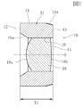
- FIG. 2 shows a cross-sectional shape of the lens unit 10.
- the lens holding member 11 is made of metal, and the condenser lens 18 is made of glass.
- the metal constituting the lens holding member 11 preferably has a linear expansion coefficient close to that of the glass material constituting the condensing lens 18, and further preferably does not contain lead in consideration of the environment.
- ferritic stainless steel SUS430 is used.
- the front end face 12 that is the light incident side and the rear end face 13 that is the light exit side are parallel to each other.
- the distance T1 between the front end face 12 and the rear end face 13, that is, the thickness dimension (length dimension) T1 in the direction along the optical axis O is about 1 to 2 mm, for example, 1.6 mm.
- the outer peripheral surface 14 of the lens holding member 11 is a cylindrical surface centered on the optical axis O of the condenser lens 18, and an outer tapered surface continuous with the outer peripheral surface 14 at the end of the light emission side (right side in FIG. 2). 14a is formed.
- the outer tapered surface 14a gradually decreases in diameter toward the light emitting side.
- the outer tapered surface 14a is a fracture surface in which a metal is broken in a punching process described later, and the surface roughness of the outer tapered surface 14a is rougher than the surface roughness of the outer peripheral surface 14.
- a lens holding hole 15 is formed in the lens holding member 11, and the lens holding hole 15 penetrates from the front end face 12 to the rear end face 13.
- the inner peripheral surface 16 of the lens holding hole 15 is a cylindrical surface with the optical axis O as the center.
- An inner tapered surface 16 a that is continuous with the inner peripheral surface 16 is formed at the end on the incident side.
- the inner tapered surface 16a is formed so that its diameter gradually increases toward the outside on the incident side.
- the condenser lens 18 is formed by being pressed inside the lens holding hole 15 and is fixed to the inner peripheral surface 16 of the cylindrical surface.
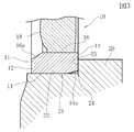
- a ring-shaped positioning recess 21 is formed in the support member 20 provided in the light emitting device 1.
- the positioning recess 21 has a cylindrical fitting inner peripheral surface 22 centered on the optical axis O and a ring shape formed so as to surround the optical axis O in a direction perpendicular to the optical axis O. And the abutting surface 23.
- the outer peripheral surface 14 of the lens holding member 11 is fitted to the fitting inner peripheral surface 22 with a minimum gap, the rear end surface 13 is abutted against the abutting surface 23, and the lens holding member 11 is positioned on the support member 20. Fixed.
- the rear end surface 13 can be positioned in close contact with the abutting surface 23 with certainty. is there.
- the lens holding member 11 is fitted into the positioning recess 21 and positioned, and the lens holding member 11 and the support member 20 are fixed by an adhesive means, a welding means, or the like.
- FIG. 4 (A) shows the metal plate material 100.
- the metal plate material 100 is a metal material having a small linear expansion coefficient with respect to the glass material forming the condenser lens 18 and is a stainless steel plate. In particular, it is possible to use a stainless steel plate that does not contain lead and is generally considered not suitable for cutting.
- the plate thickness dimension T0 of the metal plate material 100 is determined at the time of manufacture, and the tolerance width of the plate thickness dimension T0 is also large.
- the metal plate material 100 is compressed in the plate thickness direction in the compression press process to reduce the plate thickness dimension, thereby obtaining a metal plate 101 having a thickness dimension T1 as shown in FIG.
- the metal plate 101 has a flat bottom surface 112 and top surface 113.
- the plate thickness dimension T1 of the metal plate 101 is adjusted to coincide with the thickness dimension of the lens holding member 11 to be manufactured, and the width of the tolerance of the thickness dimension T1 of the metal plate 101 after being compressed is Compared to the width of the tolerance of the plate thickness dimension T0 of the metal plate material 100 shown in FIG.
- the thickness dimension T0 of the metal plate material 100 is a nominal dimension of 2.0 mm
- the thickness dimension T1 of the metal sheet 101 after compression processing is 1.6 mm.
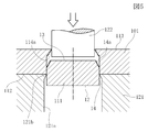
- a die 121 and a punch 122 are used.
- the die 121 is formed with a punching hole 121a, and a cutting blade 121b is formed at an upward opening edge of the punching hole 121a.
- the metal plate 101 having the thickness T1 is placed on the die 121, and the upper surface 113 of the metal plate 101 is driven by the punch 122, and the disc body 111 is punched from the metal plate 101.
- the cut surface cut by the cutting blade 121 b of the die 121 becomes the outer peripheral surface 14. Further, at the end portion on the upper surface 113 side, the metal material is broken at the breaking portion 114a, and the fracture surface continuous to the outer peripheral surface 14 is formed as the outer tapered surface 14a in the disc body 111.
- the outer tapered surface 14 a is a portion that is broken and separated from the metal plate 101 without being cut by the cutting blade 121 b, and the surface is rougher than the outer peripheral surface 14.
- the outer tapered surface 14a decreases in diameter toward the upper surface 113 of the metal plate 101.
- the punched disc body 111 has a front end face 12 and a rear end face 13, and the distance from the front end face 12 to the rear end face 13 is T1 which is the same as the thickness dimension of the metal plate 101.
- a center hole 116 is formed in the punched disc body 111.
- the central hole 116 is formed by a press punching process.
- the opening edge of the center hole 116 on the front end face 12 side is pressed and widened by a punch to form the inner tapered face 16a.
- the inner diameter of the center hole 116 is also expanded by a punch to adjust the inner diameter dimension to form the lens holding hole 15, and the lens holding member 11 shown in FIG. 7 is completed.
- the completed lens holding member 11 is sent to the lens molding process.
- the lens holding member 11 is held in the mold, and a glass material is supplied into the lens holding hole 15.
- the lens holding member 11 and the lens material are heated together and the lens material is heated to the glass transition point or higher, the lens material is pressed from above and below by the pressing mold, and the optical on the incident side of the condenser lens 18
- the surface 18a and the optical surface 18b on the emission side are transferred and formed.
- the thickness dimension T1 of the metal plate 101 is set to a highly accurate dimension with a small tolerance width, and the completed lens holding member 11 has a front end.
- a distance T1 from the surface 12 to the rear end surface 13, that is, a thickness dimension (length dimension) T1 in the direction along the optical axis O is determined with high accuracy. Therefore, when the lens holding member 11 is installed inside the lens molding die, it can be positioned with high accuracy in the optical axis direction.
- the condenser lens 18 is press-molded inside the lens holding hole 15, the distance from the rear end surface 13, which is the positioning reference surface of the lens holding member 11, to the optical surfaces 18 a and 18 b of the condenser lens 18 is determined. It becomes possible to determine with high accuracy.
- the distance between the rear end surface 13 and the optical surface 18b is short, but the distance between the front end surface 12 and the optical surface 18a is It is getting longer. Since the inner tapered surface 16a is formed in front of the optical surface 18a of the condenser lens 18, the inner peripheral surface 16 of the lens holding hole 15 does not make a shadow when collimated light is incident on the optical surface 18a. it can.
- an antireflection film is formed in the vapor deposition process on the optical surface 18a and the optical surface 18b of the completed condensing lens 18, but at this time, since the inner tapered surface 16a is formed, during the vapor deposition operation, It becomes easy to form an antireflection film over the entire surface of the optical surface 18b.
- the condenser lens 18 is press-molded inside the lens holding hole 15 of the lens holding member 11, but the glass lens completed in a manufacturing process different from the lens holding member 11 is It may be inserted into the lens holding hole 15 of the lens holding member 11 and fixed.
Landscapes
- Physics & Mathematics (AREA)
- General Physics & Mathematics (AREA)
- Optics & Photonics (AREA)
- Lens Barrels (AREA)
- Optical Couplings Of Light Guides (AREA)
Abstract
Description
前記レンズ保持部材は、厚さが所定の寸法となるように圧縮された金属板から打ち抜かれたものであり、圧縮された前記厚さ寸法によって、前記前端面と前記後端面との長さ寸法が決められていることを特徴とするものである。
(a)金属板を圧縮して板厚を所定の寸法に設定する工程と、
(b)前記(a)の工程で圧縮された金属板から、円板体を打ち抜く工程と、
(c)前記(b)の工程の後または前あるいは同時に、前記円板体の中心部にレンズ保持穴を打ち抜いてレンズ保持部材を形成する工程と、
(d)前記レンズ保持穴の内部にレンズを固定する工程と、
を有することを特徴とするものである。
すなわち、プレス加工で形成しているため、鉛を含む快削ステンレス鋼を使用する必要がない。
3 発光素子
5 コリメータレンズ
6 光アイソレータ
7 光ファイバー
10 レンズユニット
11 レンズ保持部材
12 前端面
13 後端面
14 外周面
14a 外テーパ面
15 レンズ保持穴
16a 内テーパ面
18 集光レンズ
20 支持部材
21 位置決め凹部
100 金属板素材
101 金属板
111 円板体
114a 破断部
Claims (7)
- 前端面と後端面および外周面を有し、前記前端面から前記後端面に貫通するレンズ保持穴が形成されたレンズ保持部材と、前記レンズ保持部材の内部に保持されたレンズとを有するレンズユニットにおいて、
前記レンズ保持部材は、厚さが所定の寸法となるように圧縮された金属板から打ち抜かれたものであり、圧縮された前記厚さ寸法によって、前記前端面と前記後端面との長さ寸法が決められていることを特徴とするレンズユニット。 - 前記外周面の端部に、前記金属板から打ち抜かれるときに金属の破断により形成された外テーパ面が設けられており、前記レンズ保持部材を位置決め凹部に位置決めする際に、前記外テーパ面が前記位置決め凹部の角部への対向部となる請求項1記載のレンズユニット。
- (a)金属板を圧縮して板厚を所定の寸法に設定する工程と、
(b)前記(a)の工程で圧縮された金属板から、円板体を打ち抜く工程と、
(c)前記(b)の工程の後または前あるいは同時に、前記円板体の中心部にレンズ保持穴を打ち抜いてレンズ保持部材を形成する工程と、
(d)前記レンズ保持穴の内部にレンズを固定する工程と、
を有することを特徴とするレンズユニットの製造方法。 - 前記(b)の工程では、前記円板体の外周面の端部に、金属の破断による外テーパ面を形成し、
前記レンズ保持部材を位置決め凹部に位置決めする際に、前記外テーパ面を前記位置決め凹部の角部への対向部とする請求項3記載のレンズユニットの製造方法。 - 前記(c)の工程の後または同時に、前記レンズ保持穴の端部に外部に向けて拡開する内テーパ面を形成する請求項3または4記載のレンズユニットの製造方法。
- 前記金属板は、鉛を含まないステンレス鋼である請求項3ないし5のいずれかに記載のレンズユニットの製造方法。
- 前記(d)の工程では、前記レンズ保持穴の内部にガラス素材を供給し、ガラス素材を加熱し圧縮してレンズを成形する請求項3ないし6のいずれかに記載のレンズユニットの製造方法。
Priority Applications (3)
| Application Number | Priority Date | Filing Date | Title |
|---|---|---|---|
| JP2012501733A JP5443589B2 (ja) | 2010-02-25 | 2011-02-10 | レンズユニットおよびその製造方法 |
| CN201180009947.3A CN102763015B (zh) | 2010-02-25 | 2011-02-10 | 透镜单元及其制造方法 |
| US13/564,619 US8493677B2 (en) | 2010-02-25 | 2012-08-01 | Lens unit and method of making the same |
Applications Claiming Priority (2)
| Application Number | Priority Date | Filing Date | Title |
|---|---|---|---|
| JP2010040041 | 2010-02-25 | ||
| JP2010-040041 | 2010-02-25 |
Related Child Applications (1)
| Application Number | Title | Priority Date | Filing Date |
|---|---|---|---|
| US13/564,619 Continuation US8493677B2 (en) | 2010-02-25 | 2012-08-01 | Lens unit and method of making the same |
Publications (1)
| Publication Number | Publication Date |
|---|---|
| WO2011105222A1 true WO2011105222A1 (ja) | 2011-09-01 |
Family
ID=44506636
Family Applications (1)
| Application Number | Title | Priority Date | Filing Date |
|---|---|---|---|
| PCT/JP2011/052818 Ceased WO2011105222A1 (ja) | 2010-02-25 | 2011-02-10 | レンズユニットおよびその製造方法 |
Country Status (4)
| Country | Link |
|---|---|
| US (1) | US8493677B2 (ja) |
| JP (1) | JP5443589B2 (ja) |
| CN (1) | CN102763015B (ja) |
| WO (1) | WO2011105222A1 (ja) |
Cited By (1)
| Publication number | Priority date | Publication date | Assignee | Title |
|---|---|---|---|---|
| WO2021005991A1 (ja) * | 2019-07-09 | 2021-01-14 | マクセル株式会社 | レンズユニットおよびカメラモジュール |
Families Citing this family (3)
| Publication number | Priority date | Publication date | Assignee | Title |
|---|---|---|---|---|
| JP6268856B2 (ja) * | 2013-09-24 | 2018-01-31 | 三菱電機株式会社 | 光モジュールおよびその製造方法 |
| CN113629936B (zh) * | 2016-03-02 | 2024-04-16 | Lg伊诺特有限公司 | 母线组件和包括该母线组件的马达 |
| JP6638575B2 (ja) * | 2016-06-27 | 2020-01-29 | 日亜化学工業株式会社 | 発光装置 |
Citations (4)
| Publication number | Priority date | Publication date | Assignee | Title |
|---|---|---|---|---|
| JP2001162345A (ja) * | 1999-12-10 | 2001-06-19 | Sanko:Kk | 有底筒状金属体の成形方法 |
| JP2006013358A (ja) * | 2004-06-29 | 2006-01-12 | Kyocera Corp | 光半導体素子収納用パッケージおよび光半導体装置 |
| JP2009251463A (ja) * | 2008-04-09 | 2009-10-29 | Yazaki Corp | 光通信モジュール |
| JP2010008800A (ja) * | 2008-06-27 | 2010-01-14 | Hitachi Maxell Ltd | 光学部品、光学装置 |
Family Cites Families (7)
| Publication number | Priority date | Publication date | Assignee | Title |
|---|---|---|---|---|
| US4162826A (en) * | 1978-03-20 | 1979-07-31 | Sybron Corporation | Sight glass assembly and method for its production |
| US4200794A (en) * | 1978-11-08 | 1980-04-29 | Control Data Corporation | Micro lens array and micro deflector assembly for fly's eye electron beam tubes using silicon components and techniques of fabrication and assembly |
| JPS60213916A (ja) * | 1984-04-09 | 1985-10-26 | Olympus Optical Co Ltd | 光学素子の保持装置 |
| JP3746570B2 (ja) * | 1996-07-15 | 2006-02-15 | 東芝機械株式会社 | 鏡筒付き光学素子の製造方法 |
| JP2007052096A (ja) * | 2005-08-16 | 2007-03-01 | Matsushita Electric Ind Co Ltd | レンズユニット |
| JP2008199768A (ja) | 2007-02-13 | 2008-08-28 | Calsonic Kansei Corp | ハーネスクリップの取付部構造 |
| KR100969987B1 (ko) * | 2008-01-10 | 2010-07-15 | 연세대학교 산학협력단 | 광학패키지 웨이퍼스케일 어레이 및 그 제조방법 |
-
2011
- 2011-02-10 WO PCT/JP2011/052818 patent/WO2011105222A1/ja not_active Ceased
- 2011-02-10 CN CN201180009947.3A patent/CN102763015B/zh active Active
- 2011-02-10 JP JP2012501733A patent/JP5443589B2/ja active Active
-
2012
- 2012-08-01 US US13/564,619 patent/US8493677B2/en active Active
Patent Citations (4)
| Publication number | Priority date | Publication date | Assignee | Title |
|---|---|---|---|---|
| JP2001162345A (ja) * | 1999-12-10 | 2001-06-19 | Sanko:Kk | 有底筒状金属体の成形方法 |
| JP2006013358A (ja) * | 2004-06-29 | 2006-01-12 | Kyocera Corp | 光半導体素子収納用パッケージおよび光半導体装置 |
| JP2009251463A (ja) * | 2008-04-09 | 2009-10-29 | Yazaki Corp | 光通信モジュール |
| JP2010008800A (ja) * | 2008-06-27 | 2010-01-14 | Hitachi Maxell Ltd | 光学部品、光学装置 |
Cited By (3)
| Publication number | Priority date | Publication date | Assignee | Title |
|---|---|---|---|---|
| WO2021005991A1 (ja) * | 2019-07-09 | 2021-01-14 | マクセル株式会社 | レンズユニットおよびカメラモジュール |
| JP2021012337A (ja) * | 2019-07-09 | 2021-02-04 | マクセル株式会社 | レンズユニットおよびカメラモジュール |
| JP7409794B2 (ja) | 2019-07-09 | 2024-01-09 | マクセル株式会社 | レンズユニットおよびカメラモジュール |
Also Published As
| Publication number | Publication date |
|---|---|
| CN102763015B (zh) | 2014-09-03 |
| US20120293880A1 (en) | 2012-11-22 |
| JP5443589B2 (ja) | 2014-03-19 |
| JPWO2011105222A1 (ja) | 2013-06-20 |
| CN102763015A (zh) | 2012-10-31 |
| US8493677B2 (en) | 2013-07-23 |
Similar Documents
| Publication | Publication Date | Title |
|---|---|---|
| JP5443589B2 (ja) | レンズユニットおよびその製造方法 | |
| US9434033B2 (en) | Hole cutter with extruded cap | |
| KR20170084343A (ko) | 금속 단부 단면 외주의 가공 방법 및 그 가공 방법에 의해서 얻어지는 금속 부품과 타부재의 접합 방법 | |
| JP2017209739A (ja) | フィルム状成形品の打ち抜き加工方法 | |
| CN101674902A (zh) | 具有倒角贯通孔的部件及其制造方法 | |
| US6594879B2 (en) | System, apparatus, and method for blade clearance tuning | |
| JP2008209495A5 (ja) | ||
| JP2018072499A (ja) | 結合レンズおよびレーザ光学系 | |
| US20130322071A1 (en) | Lamp-stand and lamp using the same | |
| CN107000228B (zh) | 剃须刀刀头、剃须刀刀网及剃须刀刀网的制造工艺方法 | |
| KR101866339B1 (ko) | 버 발생 방지가 가능한 플라스틱 필름절단용 프레스 칼금형 및 그 제작방법 | |
| JP6664294B2 (ja) | 打抜型の製造方法 | |
| CN108689589B (zh) | 透镜成型用模具和柱面透镜的制造方法 | |
| JP2013223873A (ja) | 金型装置 | |
| KR101735649B1 (ko) | 성형하는 동시에 절단하는 장치 | |
| CN211027703U (zh) | 一种电机外壳精密切边模具 | |
| JP2004287141A (ja) | レンズ間隔調整環 | |
| JP2017164874A (ja) | フィルム加工方法 | |
| JP2008300226A (ja) | 導光体の製造方法 | |
| CN111943486B (zh) | 用于制造表壳玻璃的方法和用于这样的方法的工具 | |
| JP2016159300A (ja) | 金属板の加工方法 | |
| CN109570611A (zh) | 一种便于薄壁铜管端头切割用模头及切割方法 | |
| TWI535555B (zh) | 鏡片製造方法 | |
| CN110333563B (zh) | 一种光学光阑的制作方法 | |
| JP3930869B2 (ja) | 半導体パッケージ用アイレットの製造方法及びその製造用プレス金型 |
Legal Events
| Date | Code | Title | Description |
|---|---|---|---|
| WWE | Wipo information: entry into national phase |
Ref document number: 201180009947.3 Country of ref document: CN |
|
| 121 | Ep: the epo has been informed by wipo that ep was designated in this application |
Ref document number: 11747186 Country of ref document: EP Kind code of ref document: A1 |
|
| WWE | Wipo information: entry into national phase |
Ref document number: 2012501733 Country of ref document: JP |
|
| NENP | Non-entry into the national phase |
Ref country code: DE |
|
| 122 | Ep: pct application non-entry in european phase |
Ref document number: 11747186 Country of ref document: EP Kind code of ref document: A1 |