WO2011105179A1 - マッサージ機 - Google Patents
マッサージ機 Download PDFInfo
- Publication number
- WO2011105179A1 WO2011105179A1 PCT/JP2011/052056 JP2011052056W WO2011105179A1 WO 2011105179 A1 WO2011105179 A1 WO 2011105179A1 JP 2011052056 W JP2011052056 W JP 2011052056W WO 2011105179 A1 WO2011105179 A1 WO 2011105179A1
- Authority
- WO
- WIPO (PCT)
- Prior art keywords
- treatment element
- shoulder
- shoulder position
- position determination
- determination
- Prior art date
- Legal status (The legal status is an assumption and is not a legal conclusion. Google has not performed a legal analysis and makes no representation as to the accuracy of the status listed.)
- Ceased
Links
Images




Classifications
-
- A—HUMAN NECESSITIES
- A61—MEDICAL OR VETERINARY SCIENCE; HYGIENE
- A61H—PHYSICAL THERAPY APPARATUS, e.g. DEVICES FOR LOCATING OR STIMULATING REFLEX POINTS IN THE BODY; ARTIFICIAL RESPIRATION; MASSAGE; BATHING DEVICES FOR SPECIAL THERAPEUTIC OR HYGIENIC PURPOSES OR SPECIFIC PARTS OF THE BODY
- A61H15/00—Massage by means of rollers, balls, e.g. inflatable, chains, or roller chains
-
- A—HUMAN NECESSITIES
- A61—MEDICAL OR VETERINARY SCIENCE; HYGIENE
- A61H—PHYSICAL THERAPY APPARATUS, e.g. DEVICES FOR LOCATING OR STIMULATING REFLEX POINTS IN THE BODY; ARTIFICIAL RESPIRATION; MASSAGE; BATHING DEVICES FOR SPECIAL THERAPEUTIC OR HYGIENIC PURPOSES OR SPECIFIC PARTS OF THE BODY
- A61H23/00—Percussion or vibration massage, e.g. using supersonic vibration; Suction-vibration massage; Massage with moving diaphragms
- A61H23/006—Percussion or tapping massage
-
- A—HUMAN NECESSITIES
- A61—MEDICAL OR VETERINARY SCIENCE; HYGIENE
- A61H—PHYSICAL THERAPY APPARATUS, e.g. DEVICES FOR LOCATING OR STIMULATING REFLEX POINTS IN THE BODY; ARTIFICIAL RESPIRATION; MASSAGE; BATHING DEVICES FOR SPECIAL THERAPEUTIC OR HYGIENIC PURPOSES OR SPECIFIC PARTS OF THE BODY
- A61H23/00—Percussion or vibration massage, e.g. using supersonic vibration; Suction-vibration massage; Massage with moving diaphragms
- A61H23/02—Percussion or vibration massage, e.g. using supersonic vibration; Suction-vibration massage; Massage with moving diaphragms with electric or magnetic drive
- A61H23/0254—Percussion or vibration massage, e.g. using supersonic vibration; Suction-vibration massage; Massage with moving diaphragms with electric or magnetic drive with rotary motor
-
- A—HUMAN NECESSITIES
- A61—MEDICAL OR VETERINARY SCIENCE; HYGIENE
- A61H—PHYSICAL THERAPY APPARATUS, e.g. DEVICES FOR LOCATING OR STIMULATING REFLEX POINTS IN THE BODY; ARTIFICIAL RESPIRATION; MASSAGE; BATHING DEVICES FOR SPECIAL THERAPEUTIC OR HYGIENIC PURPOSES OR SPECIFIC PARTS OF THE BODY
- A61H7/00—Devices for suction-kneading massage; Devices for massaging the skin by rubbing or brushing not otherwise provided for
-
- A—HUMAN NECESSITIES
- A61—MEDICAL OR VETERINARY SCIENCE; HYGIENE
- A61H—PHYSICAL THERAPY APPARATUS, e.g. DEVICES FOR LOCATING OR STIMULATING REFLEX POINTS IN THE BODY; ARTIFICIAL RESPIRATION; MASSAGE; BATHING DEVICES FOR SPECIAL THERAPEUTIC OR HYGIENIC PURPOSES OR SPECIFIC PARTS OF THE BODY
- A61H2201/00—Characteristics of apparatus not provided for in the preceding codes
- A61H2201/01—Constructive details
- A61H2201/0119—Support for the device
- A61H2201/0138—Support for the device incorporated in furniture
- A61H2201/0149—Seat or chair
-
- A—HUMAN NECESSITIES
- A61—MEDICAL OR VETERINARY SCIENCE; HYGIENE
- A61H—PHYSICAL THERAPY APPARATUS, e.g. DEVICES FOR LOCATING OR STIMULATING REFLEX POINTS IN THE BODY; ARTIFICIAL RESPIRATION; MASSAGE; BATHING DEVICES FOR SPECIAL THERAPEUTIC OR HYGIENIC PURPOSES OR SPECIFIC PARTS OF THE BODY
- A61H2201/00—Characteristics of apparatus not provided for in the preceding codes
- A61H2201/12—Driving means
- A61H2201/1207—Driving means with electric or magnetic drive
- A61H2201/1215—Rotary drive
-
- A—HUMAN NECESSITIES
- A61—MEDICAL OR VETERINARY SCIENCE; HYGIENE
- A61H—PHYSICAL THERAPY APPARATUS, e.g. DEVICES FOR LOCATING OR STIMULATING REFLEX POINTS IN THE BODY; ARTIFICIAL RESPIRATION; MASSAGE; BATHING DEVICES FOR SPECIAL THERAPEUTIC OR HYGIENIC PURPOSES OR SPECIFIC PARTS OF THE BODY
- A61H2201/00—Characteristics of apparatus not provided for in the preceding codes
- A61H2201/14—Special force transmission means, i.e. between the driving means and the interface with the user
- A61H2201/1481—Special movement conversion means
- A61H2201/149—Special movement conversion means rotation-linear or vice versa
-
- A—HUMAN NECESSITIES
- A61—MEDICAL OR VETERINARY SCIENCE; HYGIENE
- A61H—PHYSICAL THERAPY APPARATUS, e.g. DEVICES FOR LOCATING OR STIMULATING REFLEX POINTS IN THE BODY; ARTIFICIAL RESPIRATION; MASSAGE; BATHING DEVICES FOR SPECIAL THERAPEUTIC OR HYGIENIC PURPOSES OR SPECIFIC PARTS OF THE BODY
- A61H2201/00—Characteristics of apparatus not provided for in the preceding codes
- A61H2201/16—Physical interface with patient
- A61H2201/1657—Movement of interface, i.e. force application means
- A61H2201/1664—Movement of interface, i.e. force application means linear
- A61H2201/1669—Movement of interface, i.e. force application means linear moving along the body in a reciprocating manner
-
- A—HUMAN NECESSITIES
- A61—MEDICAL OR VETERINARY SCIENCE; HYGIENE
- A61H—PHYSICAL THERAPY APPARATUS, e.g. DEVICES FOR LOCATING OR STIMULATING REFLEX POINTS IN THE BODY; ARTIFICIAL RESPIRATION; MASSAGE; BATHING DEVICES FOR SPECIAL THERAPEUTIC OR HYGIENIC PURPOSES OR SPECIFIC PARTS OF THE BODY
- A61H2201/00—Characteristics of apparatus not provided for in the preceding codes
- A61H2201/50—Control means thereof
- A61H2201/5058—Sensors or detectors
- A61H2201/5071—Pressure sensors
-
- A—HUMAN NECESSITIES
- A61—MEDICAL OR VETERINARY SCIENCE; HYGIENE
- A61H—PHYSICAL THERAPY APPARATUS, e.g. DEVICES FOR LOCATING OR STIMULATING REFLEX POINTS IN THE BODY; ARTIFICIAL RESPIRATION; MASSAGE; BATHING DEVICES FOR SPECIAL THERAPEUTIC OR HYGIENIC PURPOSES OR SPECIFIC PARTS OF THE BODY
- A61H2205/00—Devices for specific parts of the body
- A61H2205/06—Arms
- A61H2205/062—Shoulders
-
- A—HUMAN NECESSITIES
- A61—MEDICAL OR VETERINARY SCIENCE; HYGIENE
- A61H—PHYSICAL THERAPY APPARATUS, e.g. DEVICES FOR LOCATING OR STIMULATING REFLEX POINTS IN THE BODY; ARTIFICIAL RESPIRATION; MASSAGE; BATHING DEVICES FOR SPECIAL THERAPEUTIC OR HYGIENIC PURPOSES OR SPECIFIC PARTS OF THE BODY
- A61H2205/00—Devices for specific parts of the body
- A61H2205/08—Trunk
- A61H2205/081—Back
-
- A—HUMAN NECESSITIES
- A61—MEDICAL OR VETERINARY SCIENCE; HYGIENE
- A61H—PHYSICAL THERAPY APPARATUS, e.g. DEVICES FOR LOCATING OR STIMULATING REFLEX POINTS IN THE BODY; ARTIFICIAL RESPIRATION; MASSAGE; BATHING DEVICES FOR SPECIAL THERAPEUTIC OR HYGIENIC PURPOSES OR SPECIFIC PARTS OF THE BODY
- A61H2230/00—Measuring physical parameters of the user
- A61H2230/85—Contour of the body
- A61H2230/855—Contour of the body used as a control parameter for the apparatus
-
- A—HUMAN NECESSITIES
- A61—MEDICAL OR VETERINARY SCIENCE; HYGIENE
- A61H—PHYSICAL THERAPY APPARATUS, e.g. DEVICES FOR LOCATING OR STIMULATING REFLEX POINTS IN THE BODY; ARTIFICIAL RESPIRATION; MASSAGE; BATHING DEVICES FOR SPECIAL THERAPEUTIC OR HYGIENIC PURPOSES OR SPECIFIC PARTS OF THE BODY
- A61H23/00—Percussion or vibration massage, e.g. using supersonic vibration; Suction-vibration massage; Massage with moving diaphragms
- A61H23/04—Percussion or vibration massage, e.g. using supersonic vibration; Suction-vibration massage; Massage with moving diaphragms with hydraulic or pneumatic drive
Definitions
- the present invention relates to a massager which massages a shoulder or the like of a user by a tapping operation or the like by a massager.
- massage machines have been widely spread as a machine for sucking and reshaping the user's human body.
- Some massage machines mechanically massage the user by, for example, a tapping operation by a massager.
- the treatment element determines the user's shoulder position by tracing the back of the user, holds the treatment element at the determined shoulder position, and strikes the shoulder. Run.
- a general shoulder position determination method will be described.
- the treatment element 8 waiting at the home position (lowermost position) is raised toward the neck while pressing against the back of the user.
- the extension Z of the treatment element 8 is changed so that the pressure applied to the rising treatment element becomes the target pressure.
- Control for raising the treatment element 8 while changing the extension Z of the treatment element 8 according to the pressure applied to the treatment element 8 may be referred to as force control rolling.
- the massage machine determines that the user is seated.
- the massage machine pauses the treatment element 8 at this position Yk.
- the massage machine lowers the treatment element 8 and returns it to the home position.
- the massage machine suspends the treatment element 8 and then raises the treatment element 8 again by force control rolling. Then, as shown in FIG.
- the treatment element 8 ascends from the home position to approximately the intermediate position Yk by force control rolling, temporarily stops the treatment element 8 at the intermediate position Yk, and then determines the position of the user's shoulder In order to do this, it is raised by force control rolling.
- the massager 8 lift following the force control rolling requires a relatively long time to maintain the accuracy of pressure monitoring.
- the rising of the treatment element 8 is temporarily stopped at the intermediate position Yk.
- the time required for the conventional shoulder position determination is long, and the massager performing the conventional shoulder position determination has a long waiting time until the massage is started. A long wait may cause the user to feel that the massager is a dull massage machine.
- raising the raising speed of the treatment element 8 while maintaining the accuracy of the shoulder position determination requires relatively expensive parts, which may result in an increase in the manufacturing cost of the massager.
- An object of the present invention is to provide a massager capable of shortening the time required for shoulder position determination.
- one aspect of the present invention provides a massage machine capable of determining a shoulder position of a user through a treatment element and performing mechanical massage from the determined shoulder position.
- This massaging machine is responsive to the treatment child moving means for simply moving the treatment child from the home position to the shoulder position judgment start position, and to detecting that the treatment child has reached the shoulder position judgment start position, And a shoulder position determination unit that executes shoulder position determination.
- the treatment element moving means executes force control rolling that raises the treatment element while changing the protrusion amount of the treatment element such that the pressure applied to the treatment element becomes a target pressure, and the target pressure is The amount of protrusion of the treatment element is predetermined so as to hardly or not increase at all.
- the shoulder position determination unit performs the shoulder position of the user according to force control rolling that moves the massager while changing the amount of protrusion of the massager such that the pressure applied to the massager becomes a target pressure.
- the shoulder position determination means descends the treatment element after temporary shoulder detection which roughly determines the shoulder position of the user by raising the treatment element from the home position and detecting the temporary shoulder. To determine the final position.
- the shoulder position determination means stops the lowering of the massaging element when the determination of the shoulder position is not completed when the lowering of the massaging element reaches the reference lowering distance or the reference lowering period. Forced termination of shoulder position determination.
- the treatment element moving means and the shoulder position determination means execute force control rolling that moves the treatment element while controlling the amount of protrusion of the treatment element such that the pressure applied to the treatment element becomes a target pressure. It is possible that the treatment element moving means lowers the target pressure when the treatment element is in the range from the home position to the position just before the shoulder position determination start position, and the shoulder position judgment means The target pressure is increased when the treatment element is in a range excluding the range from the home position to the position just before the shoulder position determination start position.
- the shoulder position determination unit does not execute the shoulder position determination during a period in which the treatment element moves in a range from the home position to a position immediately before the shoulder position determination start position.
- the shoulder position determination is started when the treatment element reaches the shoulder position determination start position.
- a massager for detecting a shoulder position of a user moves a movement range between a home position and a top position and adds a treatment element capable of changing a protrusion amount, and the treatment element
- the shoulder position determination process is performed to determine the shoulder position of the user by moving the treatment element while controlling the protrusion amount of the treatment element according to the pressure detected by the pressure sensor and the pressure sensor detecting the pressure And a possible controller.
- the controller moves the treatment element with little or no change in the projection amount of the treatment element when the treatment element is in a range from the home position to the shoulder position determination start position, and the treatment element In response to detecting that the shoulder position determination start position has been reached, the shoulder position determination process is started.
- the controller controls the protrusion amount of the treatment element in accordance with the pressure detected by the pressure sensor and the target pressure, and the treatment element moves from the home position to a position immediately before the shoulder position determination start position.
- the target pressure is decreased so that the protrusion amount of the treatment element hardly changes at all, and the target pressure is increased when the treatment element reaches the shoulder position determination start position.
- the shoulder position determination start position is apart from the home position, and is an intermediate position in the movement range of the treatment element.
- the time required for shoulder position determination can be shortened.
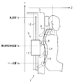
- (A), (b) is a side view and front view of a massage machine in one embodiment, respectively.
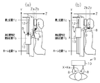
- (A), (b) is an explanatory view showing concrete operation of temporary shoulder detection operation.
- (A)-(c) is an explanatory view showing the operation mode of the conventional massage machine.
- the massage machine 1 may be a chair type including a seat 2 and a backrest 3 as shown in FIGS. 1 (a) and 1 (b).
- the backrest 3 is attached to the seat 2 so as to be tiltable in the front-rear direction by a support shaft 4 at the lower end.
- a reclining mechanism 6 for tilting the backrest 3 electrically, for example, is provided below the seating surface 5.
- An armrest 7 is fixed to the left side and the right side of the backrest 3.
- the backrest 3 is provided with a mechanical massage mechanism 9 for massaging the user.
- the mechanical massage mechanism 9 includes a pair of treatment elements 8 and a mechanism main body 10 for driving the treatment elements 8.
- the mechanism main body 10 is provided with a vertically moving motor 11 for reciprocating the mechanism main body 10 (indirectly, the treatment element 8) in the vertical direction so as to approach and separate from the seat surface 5.
- the mechanism body 10 is capable of reciprocating movement between a lowermost end position or home position Ya and a top position Yc along a guide rail 12 (see FIG. 2) extending in the longitudinal direction of the backrest 3.
- the mechanism main body 10 is provided with a strong and weak motor 13 coupled to the treatment element 8.
- the strength motor 13 operates in accordance with the drive signal, for example, displaces the treatment element 8 in the front-rear direction to change the protrusion (projection amount) Z of the treatment element 8 or vibrates the treatment element 8 finely.
- the pressing force on the user can be adjusted by changing the extension Z of the treatment element 8.
- the mechanical massage mechanism 9 can perform various mechanical massages including shoulder massage.
- the massaging machine 1 drives the vertical movement motor 11 to align the height Y of the treatment element 8 with the shoulder of the user.
- the strength motor 13 is driven to increase the cost of delivery Z of the treatment element 8 and place the treatment element 8 on the shoulder of the user.
- the mechanical massage mechanism 9 massages the user by vibrating the treatment element 8 in this state.
- the mechanical massage includes, for example, a pumping operation, a pumping operation, a rubbing operation, a finger pressing operation, and a pressing operation.
- the controller 14 of the massage machine 1 will be described with reference to FIG.
- the operation of the massager 1 is controlled by the controller 14.
- the controller 14 includes, for example, an MPU (Micro Processing Unit) and a memory.
- the controller 14 is connected to the controller 15 and the pressure sensor 19.
- the operating device 15 can be operated by the user, and can supply the controller 14 with an operation signal for setting the operation course or the operation mode of the massage machine 1 according to the operation of the user.
- the pressure sensor 19 detects the pressure applied to the treatment element 8 and supplies a sensor signal corresponding to the detected pressure to the controller 14.
- the pressure sensor 19 can be provided, for example, on the mechanical massage mechanism 9.
- the controller 14 is connected to the vertical movement motor 11 via the vertical motor drive unit 16, and is connected to the strength motor 13 via the strength motor drive unit 17.
- the user selects the operation course and the operation mode with the operation device 15, and presses the operation start button of the operation device 15.
- the controller 14 controls the vertical movement motor 11 and the strength motor 13 with the selected operation course or operation mode in accordance with the operation signal supplied from the operation device 15 to start the massage.
- the massage machine 1 is provided with a shoulder position determination device 18 that determines the shoulder position of the user via the mechanical massage mechanism 9 prior to performing the mechanical massage.
- the shoulder position determination device 18 is incorporated in the controller 14.
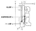
- the shoulder position determination device 18 determines the shoulder position according to the same force control rolling as in the prior art. However, during a period in which the treatment element 8 waiting at the home position Ya is raised to the shoulder position determination start position Yb, the shoulder position determination device 18 simply performs the treatment element 8 to the shoulder position determination start position Yb without performing special control. Raise it.
- the shoulder position determination start position Yb is separated from the home position Ya, and may be a substantially intermediate position of the movement range of the treatment element 8.
- Force control rolling is control for raising the treatment element 8 while changing the extension Z of the treatment element 8 such that the pressure applied to the treatment element 8 becomes a target pressure.
- Force control rolling includes position detection of the treatment element 8.
- the shoulder position determination device 18 determines whether the treatment element 8 is at the user's shoulder position or not, that is, the user's shoulder position, by checking whether the ejection margin Z has reached the threshold value Zc while the treatment element 8 is moving up. Determine
- the pressure sensor 19 starts detection of the pressure applied to the massaging element 8 when the massage machine 1 operates, and sequentially supplies a sensor signal corresponding to the detected pressure to the controller 14.
- the controller 14 can monitor the pressure applied to the treatment element 8 according to this sensor signal.
- the movement of the treatment element 8 at the time of shoulder position determination takes a serpentine locus La as shown in FIG.
- the pressure sensor 19 corresponds to a pressure detection unit.
- the shoulder position determination device 18 includes an operation of simply raising the treatment element 8 from the home position Ya to the shoulder position determination start position Yb prior to the start of the shoulder position determination, that is, the start position moving unit 20 which executes the start position movement operation. .
- the start position moving unit 20 sets the target pressure of the weakest rolling to P1 (for example, “0.1 V”) and raises the treatment element 8 by force control rolling.
- the target pressure P1 can be predetermined so that the amount of protrusion of the treatment element 8 controlled based on the pressure detected by the pressure sensor 19 and the target pressure hardly changes at all.
- the weakest rolling is a kind of force control rolling
- the cost of delivery Z of the treatment element 8 hardly or not change at all.
- the calculation load of the start position moving unit 20 is low, which is the same as when the start position moving unit 20 performs little or no control of the extension Z of the treatment element 8.
- “Simply raise (move)” means to raise (move) the treatment element 8 with little or no change in the cost of delivery Z of the treatment element 8.
- the treatment element 8 moves along a linear trajectory from the home position Ya to the shoulder position determination start position Yb.
- the start position moving unit 20 corresponds to the treatment element moving means.
- the shoulder position determination device 18 performs an operation of determining a temporary shoulder position of the user via the treatment element 8 after the treatment element height Y reaches the shoulder position determination start position Yb, that is, a temporary shoulder detection operation.
- a shoulder detection unit 21 is included.
- the temporary shoulder detection unit 21 sets the target pressure to P2 (> P1) when the treatment element 8 reaches the shoulder position determination start position Yb as shown in FIG. 5A, and the treatment element 8 is at the shoulder position From the determination start position Yb, it is raised by force control rolling.
- the target pressure P2 is predetermined so that the cost of delivery Z of the treatment element 8 changes so as to trace the surface of the back of the user.
- the temporary shoulder detection unit 21 determines that the height position of the treatment element 8 at that time is a temporary shoulder position. Stop once.
- the temporary shoulder position may be called a rough shoulder position.
- the temporary shoulder detection unit 21 performs a widening operation to widen the interval between the pair of treatment elements 8 (a treatment element interval X), and the allowance Z becomes the threshold value Zc.
- the protrusion operation to increase the protrusion amount of the treatment element 8 is simultaneously performed.
- the birthplace Z reaches the threshold Zc, the treatment element 8 is located above the shoulder of the user.
- the operation of increasing the distance between the pair of treatment elements 8 can be performed by a known mechanism, and thus the details thereof will be omitted.
- the temporary shoulder detection unit 21 constitutes a shoulder position determination unit.
- the shoulder position determination device 18 includes an operation of finally determining the shoulder position of the user through the treatment element 8 after the temporary shoulder determination, that is, the present shoulder determination unit 22 that executes this shoulder determination operation.
- the shoulder determination unit 22 monitors the sensor signal of the pressure sensor 19 while lowering the treatment element 8 located at the temporary shoulder position.
- the shoulder determining unit 22 determines that the height position of the treatment element 8 at that time is the main shoulder position. Stop the descent.
- the shoulder determination unit 22 causes the treatment element 8 to perform a tapping operation as a massaging operation at the main shoulder position.
- the shoulder determination unit 22 constitutes a shoulder position determination unit. This shoulder position may be referred to as the precise shoulder position.
- the treatment element 8 stands by at the home position Ya as shown in FIG.
- the shoulder position determination device 18 starts the shoulder position determination operation.
- the start position moving unit 20 raises the treatment element 8 from the home position Ya by the weakest rolling and moves it to the shoulder position determination start position Yb. Since the detection pressure is slight during the weakest rolling, the treatment element 8 simply rises while maintaining the extension margin Z at the minimum value Za, and reaches the shoulder position determination start position Yb in a short time.
- the treatment element 8 temporarily stops at this position.
- the start position moving unit 20 detects that the extension Z of the treatment element 8 exceeds the specified value while raising the treatment element 8 from the home position Ya to the shoulder position determination start position Yb, the massaging machine 1 It is determined that the user is not seated. In this case, the start position moving unit 20 lowers the treatment element 8 that has reached the shoulder position determination start position Yb and returns it to the home position Ya. For this reason, the treatment element 8 returns the path that has been elevated and returns to the home position Ya.
- the temporary shoulder detection unit 21 executes a temporary shoulder detection operation.
- the treatment device height Y is Yb and the outset Z is Za.
- the temporary shoulder detection unit 21 changes the target pressure of force control rolling from P1 to P2 and resumes the raising operation of the massaging element 8.
- the pressure applied to the treatment child 8 decreases with the transition from the back to the shoulder, and the prolapse Z of the treatment child 8 suddenly increases.
- the temporary shoulder detection unit 21 detects that the extra cost Z has become the threshold value Zb, the temporary shoulder detection unit 21 determines that the treatment element height Y at this point is a temporary shoulder position, and stops the increase of the treatment element 8.
- the temporary shoulder detection unit 21 stops the lifting operation of the treatment element 8 by temporary shoulder detection, as shown in FIG. 5 (b), subsequently, the widening operation for increasing the treatment element interval X to Xa; Simultaneously with the projecting operation to increase Zc to Zc.
- the treatment element 8 is prevented from interfering with the neck of the user when the production allowance Z is increased to Zc.
- the temporary shoulder detection unit 21 ends the temporary shoulder detection operation.
- the shoulder determination unit 22 executes the shoulder determination operation. As shown in FIG. 6, the shoulder determination unit 22 starts lowering the treatment element 8 with the treatment element interval X being Xa and the extension Z being Zc. At this time, the shoulder determination unit 22 lowers the treatment element 8 until the detected pressure reaches P3. When the shoulder determination unit 22 detects that the detection pressure has become P3 during this descent, the treatment element height Y at that time is determined to be the main shoulder position, and the descent of the treatment element 8 at the main shoulder position is determined. Stop it. Thereafter, the tapping operation is performed by the treatment element 8 as one operation of the mechanical massage.
- the shoulder determination unit 22 determines that the detected pressure is equal to or lower than the determination lower limit Pk (for example, “0.5 V”) even if the descending treatment element 8 reaches the determination lower end position Yd. Then, it is determined that the user is not seated, and the descent of the treatment element 8 in accordance with the present shoulder determination operation is forcibly terminated.
- the determination lower limit Pk is smaller than P3. That is, when the treatment element 8 is lowered in the shoulder determination operation, the shoulder determination unit 22 detects that the detection pressure becomes P3 when the treatment element 8 is in the range from the top position Yc to the determination lower end position Yd. If not detected, it is recognized that the user is not seated, and the descent operation according to the present shoulder determination operation is forcibly terminated, and the treatment element 8 is forcibly retracted to the home position.
- the massager 1 prior to the execution of the mechanical massage, the massager 1 simply raises the treatment element 8 waiting at the home position Ya to the shoulder position determination start position Yb of the predetermined height, and the treatment element 8 When it is detected that the shoulder position determination start position Yb is reached, the actual shoulder position determination is performed.
- the massage machine 1 does not perform shoulder position determination when the treatment element 8 is in the range from the home position Ya to the shoulder position determination start position Yb, and simply raises the treatment element 8, and the shoulder position determination is the shoulder position determination start position It is executed only in the period after Yb.
- the time required for the shoulder position determination can be shortened by the amount by which the execution range of the shoulder position determination is shortened to a part of the movable range of the treatment element 8. As a result, compared with the conventional example which starts shoulder position determination from a home position, it becomes possible for massage machine 1 of an embodiment to shorten time required for shoulder position determination.
- the massager 1 which raises the treatment element 8 standing by at the home position Ya and executes the shoulder position determination simply raises the treatment element 8 from the home position Ya to the shoulder position determination start position Yb and starts the shoulder position determination
- shoulder position determination is performed. Since it is sufficient to simply raise the treatment element from the home position to the shoulder position judgment start position, the time required for raising the treatment element to the shoulder position judgment start position can be shortened. The time required for shoulder position determination can be shortened. Therefore, since the waiting time from the start operation of the mechanical massage by the operation device 15 to the actual start of the massage can be short, the user does not feel that the massager is a dull massage machine. .
- the massage machine 1 raises the treatment element 8 by the weakest rolling in the range from the home position Ya to the shoulder position determination start position Yb, so the user of the massage machine 1 can increase the rising speed of the treatment element 8 It is possible to detect if the seat is seated. When the user is not seated, the treatment element 8 can be returned to the home position.
- the massage machine 1 detects the pressure applied to the treatment element 8 with the pressure sensor 19, and determines the user's shoulder position determination from the detected pressure. By directly tracing the user's body (back) with the treatment element 8, the user's shoulder position can be determined with high accuracy.
- the massage machine 1 performs the shoulder position of the user with high accuracy by force control rolling which raises the treatment element 8 while changing the extension Z of the treatment element 8 so that the pressure applied to the treatment element 8 becomes the target pressure. Can be determined.
- the temporary shoulder detection operation is performed based on the pressure applied to the treatment element 8 rising, and this shoulder determination operation based on the pressure applied to the treatment element 8 falling after detection of the temporary shoulder position To determine the final shoulder position. Therefore, first, the shoulder position is roughly determined by the temporary shoulder detection operation, and the shoulder position is finely determined by the subsequent shoulder determination operation, so that the shoulder position of the user can be accurately determined.
- the embodiment is not limited to the configuration described above, and may be changed to the following modes.
- the rising speed of the treatment element 8 during the start position moving operation and the rising speed of the treatment element 8 during the temporary shoulder detection operation are not limited to the same.
- the rising speed of the former may be faster than the latter. In this case, even if the rising speed of the treatment element 8 is increased in the range from the home position Ya to the shoulder position determination start position Yb, the accuracy of the shoulder position determination is not affected, so the time required for the shoulder position determination is further shortened. You can also
- the start position movement operation is not limited to the weakest rolling, and may be, for example, a simple upward operation not performing force control rolling.
- the treatment element 8 reaches the shoulder position determination start position Yb, it is not limited to temporarily stop at this position Yb. That is, even if the treatment element 8 reaches the shoulder position determination start position Yb, the rising operation may be continued without stopping at this position Yb, and the transition from the start position movement operation to the temporary shoulder detection operation may be seamless.
- the shoulder position determination start position Yb is not limited to the substantially intermediate position, and the point may be any predetermined position higher than the home position Ya.
- the shoulder position determination is not limited to the method of determining based on the detection pressure applied to the treatment element 8.
- the shape of the human body of the user may be specified by the degree of light reflection by the light sensor.
- the shoulder position determination is not limited to a method in which a temporary shoulder detection operation is used to index a temporary shoulder, and then this shoulder determination operation is used to determine a final shoulder position. For example, only temporary shoulder detection operation may be performed.
- the weak rolling performed at the time of the start position moving operation is not limited to the weakest rolling, and may be any one that has a target pressure lower than that of normal rolling.
- the shoulder position determination is not limited to that by force control rolling, and other determination methods may be used.
- the forced downward stop of the treatment element 8 in the shoulder determination operation is not limited to the determination lower limit value Pk or less even when the treatment element 8 passes the determination lower end position Yd.
- the condition may be that the detected pressure does not satisfy P3 even if the treatment element 8 passes the determination lower end position Yd.
- the forced downward stop of the treatment element 8 in this shoulder determination operation may be conditioned on, for example, that the detected pressure does not reach the predetermined pressure within a certain fixed time.
- the lower determination end position Yd is not limited to a height slightly lower than the shoulder position determination start position Yb, and can be changed as appropriate.
- the drive source of the mechanical massage mechanism 9 is not limited to the motor, and may be, for example, a cylinder or a solenoid.
- the mechanical massage mechanism 9 is not limited to the structure of the embodiment, and can be changed as appropriate.
- the massager 1 is not limited to a machine type capable of performing only mechanical massage, and may also be capable of performing pneumatic massage with an air bag, for example.
- the shoulder position determination means moves the treatment element in the upward direction from the home position to confirm the shoulder of the user, and then the pair of treatment elements are At the same time, the widening operation for separating the treatment elements from each other in the width direction and the projecting operation for causing the treatment elements to largely fly out are performed. According to this configuration, since the separation operation and the projection operation of the treatment element are simultaneously performed, it is possible to shorten the time required to actually start the mechanical massage from the shoulder position determination.
- the device further comprises a pressure detection means for detecting the pressure applied to the treatment element, and the treatment element moving means or the shoulder position judgment means Based on the pressure applied to the treatment device, the shoulder position of the user is determined.
- the shoulder position of the user is determined based on the pressure applied to the massager, the shoulder position of the user can be determined by an accurate form of tracing the body of the user directly by the massager. It becomes possible.
Landscapes
- Health & Medical Sciences (AREA)
- Epidemiology (AREA)
- Pain & Pain Management (AREA)
- Physical Education & Sports Medicine (AREA)
- Rehabilitation Therapy (AREA)
- Life Sciences & Earth Sciences (AREA)
- Animal Behavior & Ethology (AREA)
- General Health & Medical Sciences (AREA)
- Public Health (AREA)
- Veterinary Medicine (AREA)
- Dermatology (AREA)
- Massaging Devices (AREA)
Abstract
Description
マッサージ機1は、図1(a),(b)に示すように、座部2と背もたれ部3とを含む椅子型であり得る。背もたれ部3は、下端の支軸4によって前後方向に傾動可能に座部2に取り付けられている。座面5の下方には、例えば電動で背もたれ部3を傾動させるリクライニング機構6が設けられている。背もたれ部3の左側面及び右側面には、肘掛け部7が固定されている。
まず、マッサージ機1が停止している際、施療子8は、図4に示すようにホーム位置Yaで待機する。マッサージ機1が動作を開始すると、肩位置判定装置18が肩位置判定動作を開始する。このとき、開始位置移動部20は、施療子8をホーム位置Yaから最弱ローリングにより上昇させて、肩位置判定開始位置Ybまで移動させる。最弱ローリング中は検出圧力が僅かであるので、施療子8は出代Zが最小値Zaに維持されたまま単に上昇し、短時間で肩位置判定開始位置Ybに到達する。施療子8が肩位置判定開始位置Ybに至ると、施療子8がこの位置で一旦停止する。
(1)ホーム位置Yaで待機する施療子8を上昇させて肩位置判定を実行するマッサージ機1は、施療子8をホーム位置Yaから肩位置判定開始位置Ybまで単に上昇させ、肩位置判定開始位置Ybに到達したのを検出したのに応答して、肩位置判定を行う。ホーム位置から肩位置判定開始位置までは、施療子を単に上昇させれば済むので、施療子を肩位置判定開始位置まで上昇させる際の所要時間が短く済む。肩位置判定に必要な時間を短くすることができる。よって、操作器15で機械式マッサージの開始操作が行われてから実際のマッサージか開始されるまでの待ち時間が短く済むので、動作の鈍重なマッサージ機であると使用者に感じさせずに済む。
・開始位置移動動作中の施療子8の上昇速度と、仮肩検出動作中の施療子8の上昇速度とは、同じであることに限定されない。例えば、前者の上昇速度を後者よりも速くしてもよい。この場合、ホーム位置Yaから肩位置判定開始位置Ybまでの範囲において施療子8の上昇速度を高めても、肩位置判定の精度に影響は生じないから、肩位置判定に必要な時間を更に短くすることもできる。
・施療子8が肩位置判定開始位置Ybに到達した際、この位置Ybで一旦停止することに限定されない。即ち、施療子8が肩位置判定開始位置Ybに到達しても、この位置Ybでは停止せずに上昇動作が継続され、開始位置移動動作からシームレスに仮肩検出動作に移行するものでもよい。
・肩位置判定は、施療子8に加わる検出圧力を基に判定する方式に限定されず、例えば光センサによる光の反射具合により使用者の人体形状を特定するものでもよい。
・開始位置移動動作時に行う弱ローリングは、最弱ローリングに限定されず、通常のローリングよりも目標圧力が低いものであればよい。
・本肩決定動作での施療子8の下降強制停止は、施療子8が判定下端位置Ydを過ぎても判定下限値Pk以下となることに限定されない。例えば、施療子8が判定下端位置Ydを過ぎても検出圧力がP3を満たしていないことを条件としてもよい。
・判定下端位置Ydは、肩位置判定開始位置Ybよりも少し低い高さに限定されず、適宜変更可能である。
次に、上記実施形態及び別例から把握できる技術的思想について、それらの効果とともに以下に追記する。
Claims (10)
- 施療子を介して使用者の肩位置を判定し、判定された肩位置から機械式マッサージを実行可能なマッサージ機において、
前記施療子をホーム位置から肩位置判定開始位置へ単に移動させる施療子移動手段と、
前記施療子が前記肩位置判定開始位置に到達したことを検出したのに応答して、肩位置判定を実行する肩位置判定手段と
を備えたことを特徴とするマッサージ機。 - 前記施療子移動手段は、前記施療子に加わる圧力が目標圧力になるように当該施療子の突出量を変更しながら前記施療子を上昇させる力制御ローリングを実行し、前記目標圧力は前記施療子の突出量がほとんど又は全く増加しないように予め決められている
ことを特徴とする請求項1に記載のマッサージ機。 - 前記肩位置判定手段は、前記施療子に加わる圧力が目標圧力になるように当該施療子の突出量を変更しながら前記施療子を移動させる力制御ローリングに従って、前記使用者の肩位置を判定する
ことを特徴とする請求項1又は2に記載のマッサージ機。 - 前記肩位置判定手段は、前記施療子を前記ホーム位置から上昇して前記使用者の肩位置をおおまかに判定する仮肩検出と、当該仮肩検出の後、前記施療子を下降して最終的な肩位置を判定する本肩決定とを実行する
ことを特徴とする請求項1~3のうちいずれか一項に記載のマッサージ機。 - 前記肩位置判定手段は、前記施療子の下降が参照下降距離又は参照下降期間に達した時点で前記肩位置の判定が完了しないとき、前記施療子の下降を停止して前記肩位置判定を強制終了する
ことを特徴とする請求項4に記載のマッサージ機。 - 前記施療子移動手段及び前記肩位置判定手段は、前記施療子に加わる圧力が目標圧力になるように当該施療子の突出量を制御しながら前記施療子を移動させる力制御ローリングを実行可能であり、
前記施療子移動手段は、前記施療子が前記ホーム位置から肩位置判定開始位置の直前位置までの範囲にあるときに、前記目標圧力を低下させ、
前記肩位置判定手段は、前記施療子が前記ホーム位置から肩位置判定開始位置の直前位置までの範囲を除く範囲にあるときに、前記目標圧力を増加させる
ことを特徴とする請求項1に記載のマッサージ機。 - 前記肩位置判定手段は、前記施療子が前記ホーム位置から前記肩位置判定開始位置の直前位置までの範囲内を移動している期間中に、前記肩位置判定を実行せず、前記施療子が前記肩位置判定開始位置に到達した時点で前記肩位置判定を開始する
ことを特徴とする請求項1に記載のマッサージ機。 - 使用者の肩位置を検出するマッサージ機において、
ホーム位置と最上位置との間の移動範囲を移動しかつ突出量を変更可能な施療子と、
前記施療子に加わる圧力を検出する圧力センサと、
前記圧力センサの検出した圧力に従って前記施療子の突出量を制御しながら、前記施療子を移動させることで、使用者の肩位置を判定する肩位置判定処理を実行可能なコントローラとを備え、前記コントローラは、
前記施療子が前記ホーム位置から肩位置判定開始位置までの範囲内にあるとき、前記施療子の突出量をほとんど又は全く変更することなく前記施療子を移動させ、
前記施療子が前記肩位置判定開始位置に到達したことを検出したのに応答して、前記肩位置判定処理を開始する
ことを特徴とするマッサージ機。 - 前記コントローラは、
前記圧力センサの検出した圧力と目標圧力とに従って、前記施療子の突出量を制御するものであり、
前記施療子が前記ホーム位置から肩位置判定開始位置の直前位置までの範囲内にあるとき、前記施療子の突出量がほとんど又は全く変更しないように、前記目標圧力を低下させ、
前記施療子が前記肩位置判定開始位置に達した時点で、前記目標圧力を増加させることを特徴とする請求項8に記載のマッサージ機。 - 前記肩位置判定開始位置は、前記ホーム位置から離間しており、前記施療子の移動範囲における中間位置であることを特徴とする請求項8又は9に記載のマッサージ機。
Priority Applications (1)
| Application Number | Priority Date | Filing Date | Title |
|---|---|---|---|
| CN2011800062731A CN102844010A (zh) | 2010-02-23 | 2011-02-01 | 按摩机 |
Applications Claiming Priority (2)
| Application Number | Priority Date | Filing Date | Title |
|---|---|---|---|
| JP2010-037161 | 2010-02-23 | ||
| JP2010037161A JP5232181B2 (ja) | 2010-02-23 | 2010-02-23 | マッサージ機 |
Publications (1)
| Publication Number | Publication Date |
|---|---|
| WO2011105179A1 true WO2011105179A1 (ja) | 2011-09-01 |
Family
ID=44506600
Family Applications (1)
| Application Number | Title | Priority Date | Filing Date |
|---|---|---|---|
| PCT/JP2011/052056 Ceased WO2011105179A1 (ja) | 2010-02-23 | 2011-02-01 | マッサージ機 |
Country Status (5)
| Country | Link |
|---|---|
| JP (1) | JP5232181B2 (ja) |
| KR (1) | KR20120109554A (ja) |
| CN (1) | CN102844010A (ja) |
| TW (1) | TWI403315B (ja) |
| WO (1) | WO2011105179A1 (ja) |
Cited By (5)
| Publication number | Priority date | Publication date | Assignee | Title |
|---|---|---|---|---|
| EP2772241A4 (en) * | 2011-10-24 | 2015-05-20 | Ceragem Co Ltd | METHOD FOR BODY TYPE DETERMINATION FOR A THERMAL THERAPY DEVICE |
| CN107031536A (zh) * | 2015-09-21 | 2017-08-11 | 大众汽车有限公司 | 用于控制至少一个机电构件的运动的方法和系统 |
| CN109512646A (zh) * | 2018-12-28 | 2019-03-26 | 浙江豪中豪健康产品有限公司 | 一种按摩椅机械手的体型检测装置 |
| EP3338754A4 (en) * | 2015-09-25 | 2019-08-07 | Ceragem Co., Ltd. | METHOD FOR CONTROLLING ACUPRESSURE FORCE AND BODY SEARCH IN REAL TIME |
| CN113133911A (zh) * | 2020-12-28 | 2021-07-20 | 未来穿戴技术有限公司 | 按摩仪的控制方法及装置、电子设备、存储介质 |
Families Citing this family (9)
| Publication number | Priority date | Publication date | Assignee | Title |
|---|---|---|---|---|
| JP6247445B2 (ja) * | 2013-02-14 | 2017-12-13 | マクセルホールディングス株式会社 | マッサージ機 |
| JP6191917B2 (ja) * | 2013-12-11 | 2017-09-06 | パナソニックIpマネジメント株式会社 | マッサージ機 |
| CN108379023B (zh) * | 2017-02-26 | 2019-08-30 | 张艳平 | 一种医疗骨科用磁疗活血康复治疗仪 |
| CN106901958B (zh) * | 2017-04-22 | 2018-02-09 | 栾雷 | 一种背部按摩座椅 |
| JP6770604B2 (ja) * | 2019-04-01 | 2020-10-14 | 株式会社フジ医療器 | マッサージ機 |
| CN110680688B (zh) * | 2019-09-05 | 2022-12-20 | 蒙发利稻田健康科技(厦门)有限公司 | 一种按摩床 |
| CN111012095A (zh) * | 2019-12-31 | 2020-04-17 | 北京黎明文仪家具有限公司 | 一种基于大数据的办公椅按摩控制方法及系统 |
| JP7488113B2 (ja) * | 2020-05-29 | 2024-05-21 | 株式会社フジ医療器 | マッサージ機 |
| CN112006903B (zh) * | 2020-09-08 | 2022-10-18 | 上海荣泰健康科技股份有限公司 | 按摩椅肩部位置检测与校正方法、装置、设备、按摩椅 |
Citations (3)
| Publication number | Priority date | Publication date | Assignee | Title |
|---|---|---|---|---|
| JP2005334477A (ja) * | 2004-05-28 | 2005-12-08 | Matsushita Electric Works Ltd | マッサージ椅子 |
| JP2008049177A (ja) * | 2007-11-02 | 2008-03-06 | Family Co Ltd | マッサージ機 |
| JP2009240687A (ja) * | 2008-03-31 | 2009-10-22 | Panasonic Electric Works Co Ltd | マッサージ機 |
-
2010
- 2010-02-23 JP JP2010037161A patent/JP5232181B2/ja active Active
-
2011
- 2011-02-01 KR KR1020127018013A patent/KR20120109554A/ko not_active Ceased
- 2011-02-01 WO PCT/JP2011/052056 patent/WO2011105179A1/ja not_active Ceased
- 2011-02-01 CN CN2011800062731A patent/CN102844010A/zh active Pending
- 2011-02-10 TW TW100104392A patent/TWI403315B/zh not_active IP Right Cessation
Patent Citations (3)
| Publication number | Priority date | Publication date | Assignee | Title |
|---|---|---|---|---|
| JP2005334477A (ja) * | 2004-05-28 | 2005-12-08 | Matsushita Electric Works Ltd | マッサージ椅子 |
| JP2008049177A (ja) * | 2007-11-02 | 2008-03-06 | Family Co Ltd | マッサージ機 |
| JP2009240687A (ja) * | 2008-03-31 | 2009-10-22 | Panasonic Electric Works Co Ltd | マッサージ機 |
Cited By (9)
| Publication number | Priority date | Publication date | Assignee | Title |
|---|---|---|---|---|
| EP2772241A4 (en) * | 2011-10-24 | 2015-05-20 | Ceragem Co Ltd | METHOD FOR BODY TYPE DETERMINATION FOR A THERMAL THERAPY DEVICE |
| US10588683B2 (en) | 2011-10-24 | 2020-03-17 | Ceragem Co., Ltd. | Method for determining body type for thermotherapy device |
| CN107031536A (zh) * | 2015-09-21 | 2017-08-11 | 大众汽车有限公司 | 用于控制至少一个机电构件的运动的方法和系统 |
| EP3338754A4 (en) * | 2015-09-25 | 2019-08-07 | Ceragem Co., Ltd. | METHOD FOR CONTROLLING ACUPRESSURE FORCE AND BODY SEARCH IN REAL TIME |
| US10744065B2 (en) | 2015-09-25 | 2020-08-18 | Ceragem Co., Ltd | Method for controlling acupressure force and body scan in real-time |
| EP3892252A1 (en) * | 2015-09-25 | 2021-10-13 | Ceragem Co., Ltd. | A driving module for controlling a human body scan in real time |
| CN109512646A (zh) * | 2018-12-28 | 2019-03-26 | 浙江豪中豪健康产品有限公司 | 一种按摩椅机械手的体型检测装置 |
| CN109512646B (zh) * | 2018-12-28 | 2023-09-29 | 浙江豪中豪健康产品有限公司 | 一种按摩椅机械手的体型检测装置 |
| CN113133911A (zh) * | 2020-12-28 | 2021-07-20 | 未来穿戴技术有限公司 | 按摩仪的控制方法及装置、电子设备、存储介质 |
Also Published As
| Publication number | Publication date |
|---|---|
| CN102844010A (zh) | 2012-12-26 |
| JP5232181B2 (ja) | 2013-07-10 |
| KR20120109554A (ko) | 2012-10-08 |
| TW201143749A (en) | 2011-12-16 |
| JP2011172638A (ja) | 2011-09-08 |
| TWI403315B (zh) | 2013-08-01 |
Similar Documents
| Publication | Publication Date | Title |
|---|---|---|
| JP5232181B2 (ja) | マッサージ機 | |
| KR102622968B1 (ko) | 상지 운동 장치 | |
| KR100256438B1 (ko) | 마사지기 | |
| CN1182824C (zh) | 椅子型按摩机 | |
| JP4449577B2 (ja) | マッサージ椅子 | |
| JP2009034242A (ja) | マッサージ機 | |
| KR20190006234A (ko) | 자동 속도 조절이 가능한 런닝머신 | |
| JPH0531147A (ja) | 椅子式マツサージ機 | |
| JP2018038676A (ja) | マッサージ機 | |
| JP6247445B2 (ja) | マッサージ機 | |
| JP2010279589A (ja) | マッサージ機 | |
| KR20060122717A (ko) | 마사지기 | |
| JP2014180509A (ja) | マッサージ機 | |
| WO2017094128A1 (ja) | 介助装置 | |
| JP4636749B2 (ja) | 椅子型マッサージ機 | |
| JP3667895B2 (ja) | マッサージ機 | |
| JP3857775B2 (ja) | マッサージ機 | |
| KR102722275B1 (ko) | 안마장치 및 안마장치의 제어방법 | |
| JP2015104639A (ja) | マッサージ部 | |
| JP5936494B2 (ja) | マッサージ機 | |
| JP2010148754A (ja) | 運動促進機能付座席装置 | |
| JP3710897B2 (ja) | マッサージ機 | |
| JP3667896B2 (ja) | マッサージ機 | |
| CN104722878B (zh) | 自动点焊机头 | |
| JP2009240687A (ja) | マッサージ機 |
Legal Events
| Date | Code | Title | Description |
|---|---|---|---|
| WWE | Wipo information: entry into national phase |
Ref document number: 201180006273.1 Country of ref document: CN |
|
| 121 | Ep: the epo has been informed by wipo that ep was designated in this application |
Ref document number: 11747143 Country of ref document: EP Kind code of ref document: A1 |
|
| ENP | Entry into the national phase |
Ref document number: 20127018013 Country of ref document: KR Kind code of ref document: A |
|
| NENP | Non-entry into the national phase |
Ref country code: DE |
|
| 122 | Ep: pct application non-entry in european phase |
Ref document number: 11747143 Country of ref document: EP Kind code of ref document: A1 |