WO2011104765A1 - 導光板及び導光板の製造方法 - Google Patents
導光板及び導光板の製造方法 Download PDFInfo
- Publication number
- WO2011104765A1 WO2011104765A1 PCT/JP2010/001335 JP2010001335W WO2011104765A1 WO 2011104765 A1 WO2011104765 A1 WO 2011104765A1 JP 2010001335 W JP2010001335 W JP 2010001335W WO 2011104765 A1 WO2011104765 A1 WO 2011104765A1
- Authority
- WO
- WIPO (PCT)
- Prior art keywords
- guide plate
- light
- coating
- light guide
- fine particles
- Prior art date
- Legal status (The legal status is an assumption and is not a legal conclusion. Google has not performed a legal analysis and makes no representation as to the accuracy of the status listed.)
- Ceased
Links
Images














Classifications
-
- G—PHYSICS
- G02—OPTICS
- G02B—OPTICAL ELEMENTS, SYSTEMS OR APPARATUS
- G02B6/00—Light guides; Structural details of arrangements comprising light guides and other optical elements, e.g. couplings
- G02B6/0001—Light guides; Structural details of arrangements comprising light guides and other optical elements, e.g. couplings specially adapted for lighting devices or systems
- G02B6/0011—Light guides; Structural details of arrangements comprising light guides and other optical elements, e.g. couplings specially adapted for lighting devices or systems the light guides being planar or of plate-like form
- G02B6/0033—Means for improving the coupling-out of light from the light guide
- G02B6/0035—Means for improving the coupling-out of light from the light guide provided on the surface of the light guide or in the bulk of it
- G02B6/004—Scattering dots or dot-like elements, e.g. microbeads, scattering particles, nanoparticles
-
- G—PHYSICS
- G02—OPTICS
- G02B—OPTICAL ELEMENTS, SYSTEMS OR APPARATUS
- G02B6/00—Light guides; Structural details of arrangements comprising light guides and other optical elements, e.g. couplings
- G02B6/0001—Light guides; Structural details of arrangements comprising light guides and other optical elements, e.g. couplings specially adapted for lighting devices or systems
- G02B6/0011—Light guides; Structural details of arrangements comprising light guides and other optical elements, e.g. couplings specially adapted for lighting devices or systems the light guides being planar or of plate-like form
- G02B6/0013—Means for improving the coupling-in of light from the light source into the light guide
- G02B6/0015—Means for improving the coupling-in of light from the light source into the light guide provided on the surface of the light guide or in the bulk of it
- G02B6/0016—Grooves, prisms, gratings, scattering particles or rough surfaces
-
- G—PHYSICS
- G02—OPTICS
- G02B—OPTICAL ELEMENTS, SYSTEMS OR APPARATUS
- G02B6/00—Light guides; Structural details of arrangements comprising light guides and other optical elements, e.g. couplings
- G02B6/0001—Light guides; Structural details of arrangements comprising light guides and other optical elements, e.g. couplings specially adapted for lighting devices or systems
- G02B6/0011—Light guides; Structural details of arrangements comprising light guides and other optical elements, e.g. couplings specially adapted for lighting devices or systems the light guides being planar or of plate-like form
- G02B6/0033—Means for improving the coupling-out of light from the light guide
- G02B6/0035—Means for improving the coupling-out of light from the light guide provided on the surface of the light guide or in the bulk of it
- G02B6/004—Scattering dots or dot-like elements, e.g. microbeads, scattering particles, nanoparticles
- G02B6/0043—Scattering dots or dot-like elements, e.g. microbeads, scattering particles, nanoparticles provided on the surface of the light guide
-
- G—PHYSICS
- G02—OPTICS
- G02B—OPTICAL ELEMENTS, SYSTEMS OR APPARATUS
- G02B6/00—Light guides; Structural details of arrangements comprising light guides and other optical elements, e.g. couplings
- G02B6/0001—Light guides; Structural details of arrangements comprising light guides and other optical elements, e.g. couplings specially adapted for lighting devices or systems
- G02B6/0011—Light guides; Structural details of arrangements comprising light guides and other optical elements, e.g. couplings specially adapted for lighting devices or systems the light guides being planar or of plate-like form
- G02B6/0033—Means for improving the coupling-out of light from the light guide
- G02B6/0058—Means for improving the coupling-out of light from the light guide varying in density, size, shape or depth along the light guide
-
- G—PHYSICS
- G02—OPTICS
- G02B—OPTICAL ELEMENTS, SYSTEMS OR APPARATUS
- G02B6/00—Light guides; Structural details of arrangements comprising light guides and other optical elements, e.g. couplings
- G02B6/0001—Light guides; Structural details of arrangements comprising light guides and other optical elements, e.g. couplings specially adapted for lighting devices or systems
- G02B6/0011—Light guides; Structural details of arrangements comprising light guides and other optical elements, e.g. couplings specially adapted for lighting devices or systems the light guides being planar or of plate-like form
- G02B6/0065—Manufacturing aspects; Material aspects
-
- G—PHYSICS
- G02—OPTICS
- G02F—OPTICAL DEVICES OR ARRANGEMENTS FOR THE CONTROL OF LIGHT BY MODIFICATION OF THE OPTICAL PROPERTIES OF THE MEDIA OF THE ELEMENTS INVOLVED THEREIN; NON-LINEAR OPTICS; FREQUENCY-CHANGING OF LIGHT; OPTICAL LOGIC ELEMENTS; OPTICAL ANALOGUE/DIGITAL CONVERTERS
- G02F1/00—Devices or arrangements for the control of the intensity, colour, phase, polarisation or direction of light arriving from an independent light source, e.g. switching, gating or modulating; Non-linear optics
- G02F1/01—Devices or arrangements for the control of the intensity, colour, phase, polarisation or direction of light arriving from an independent light source, e.g. switching, gating or modulating; Non-linear optics for the control of the intensity, phase, polarisation or colour
- G02F1/13—Devices or arrangements for the control of the intensity, colour, phase, polarisation or direction of light arriving from an independent light source, e.g. switching, gating or modulating; Non-linear optics for the control of the intensity, phase, polarisation or colour based on liquid crystals, e.g. single liquid crystal display cells
- G02F1/133—Constructional arrangements; Operation of liquid crystal cells; Circuit arrangements
- G02F1/1333—Constructional arrangements; Manufacturing methods
- G02F1/1335—Structural association of cells with optical devices, e.g. polarisers or reflectors
- G02F1/1336—Illuminating devices
- G02F1/133602—Direct backlight
- G02F1/133606—Direct backlight including a specially adapted diffusing, scattering or light controlling members
-
- G—PHYSICS
- G02—OPTICS
- G02B—OPTICAL ELEMENTS, SYSTEMS OR APPARATUS
- G02B6/00—Light guides; Structural details of arrangements comprising light guides and other optical elements, e.g. couplings
- G02B6/0001—Light guides; Structural details of arrangements comprising light guides and other optical elements, e.g. couplings specially adapted for lighting devices or systems
- G02B6/0011—Light guides; Structural details of arrangements comprising light guides and other optical elements, e.g. couplings specially adapted for lighting devices or systems the light guides being planar or of plate-like form
- G02B6/0033—Means for improving the coupling-out of light from the light guide
- G02B6/0058—Means for improving the coupling-out of light from the light guide varying in density, size, shape or depth along the light guide
- G02B6/0061—Means for improving the coupling-out of light from the light guide varying in density, size, shape or depth along the light guide to provide homogeneous light output intensity
Definitions
- the present invention relates to a surface light source device that emits light from the back surface of a liquid crystal display panel, a signboard, etc., a light guide plate for a so-called backlight device, and a method for manufacturing the light guide plate, and in particular, a diffusion portion is formed on at least the front surface or the back surface of the light guide plate.
- the present invention relates to a light guide plate and a method for manufacturing the light guide plate.
- a backlight device that emits light from the back of a liquid crystal display panel, a signboard, etc. has a light source arranged in a plane and a direct type that forms a uniform light emission by a diffuser plate, etc., and a linear light source arranged on the end face of the light guide plate
- a light guide plate system called edge light or side light is known.
- LEDs Light Emitting Diodes
- the light guide plate for the backlight device has a diffusing material dispersed inside the light guide plate, or provided with a light diffusion layer or a diffusion pattern on at least one of the front surface and the back surface.
- This light guide plate allows light to enter the light guide plate from a cold cathode tube or LED array light source provided on the end face, and emit light to the output side to form a surface light source device.
- a technique for providing a gradation distribution is known (see Patent Document 1).
- the gradation distribution increases the light diffusion capability of the diffusion layer as the distance from the light source increases so that the brightness of the exit surface of the backlight device becomes uniform.
- a method of providing a gradation distribution by a diffusion layer or a diffusion pattern a method of transferring a concavo-convex pattern by injection molding using a mold or press molding is known. A desired gradation pattern is formed in advance on the mold. Also known is a method of dot-printing light diffusing ink by screen printing (see Patent Document 2).
- the diffusion layer formed on the light guide plate base material needs to have finer and smaller pitches in the individual diffusion portions so that the pattern of the diffusion layer is not noticeable.
- display devices are required to be thin.
- the pattern of the diffusion layer is easily noticeable. Therefore, it is necessary to further refine the pattern of the diffusion layer and reduce the pitch.
- An object of the present invention is to provide a light guide plate and a method of manufacturing the light guide plate that can form a fine pattern of a diffusion layer easily and inexpensively.
- the light guide plate manufacturing method is a light guide plate manufacturing method in which a light source is disposed on an end face to constitute a surface light source device, and the light diffusing fine particles are formed on the back surface or front surface or both surfaces of the light guide plate substrate. And a coating liquid containing a light-transmitting binder is applied in the form of fine droplets to coat the diffusion layer, the light diffusing fine particles are aggregated, and the aggregate occupied by the aggregate on the coated surface of the light guide plate base material.
- the ratio between the area and the application area of the coating solution is set to 0.1% to 70%.
- the portion near the light source has a low coating density of the light diffusing fine particles, and the portion far from the light source has a high coating density of the light diffusing fine particles.
- the coating liquid is applied to the back surface, the front surface, or both surfaces of the light guide plate base material by a spray coating method in which the coating liquid is sprayed from a nozzle.
- the spray coating method can achieve the purpose with inexpensive equipment because it is only a light and small nozzle that scans in the XY direction. That is, the spray coating method is applied to a large light guide plate with inexpensive equipment.
- the coating density of the light diffusing fine particles is changed one-dimensionally or two-dimensionally by arranging a plurality of nozzles in parallel and scanning the plurality of nozzles substantially in parallel.
- the distance from the nozzle to the coating surface of the light guide plate substrate is 70 mm or more and 300 mm or less.
- the nozzle is moved in a direction substantially parallel to the first side of the light guide plate base material on the coating surface of the light guide plate base material while ejecting the coating liquid from the nozzle. It is preferable that the coating liquid is applied to the entire surface or a part of the coating surface by repeating at a predetermined feed pitch in a direction orthogonal to the first side.
- the step of repeating the scanning for moving the nozzle in a direction substantially parallel to the first side of the light guide plate base material at a predetermined feed pitch in a direction orthogonal to the first side is applied to the light guide plate base material. It is preferable to change the coating density of the light diffusing fine particles one-dimensionally by partially repeating on the work surface.
- the coating density of the light diffusing fine particles is one-dimensionally changed. It is preferable to change.
- the amount of coating liquid applied from the nozzle per unit time is changed for each scanning of the nozzle, and the light-diffusing fine particles are applied by coating the coating liquid on the whole or part of the coating surface of the light guide plate substrate. It is preferable to change the coating density in a one-dimensional manner.
- a light guide plate is a light guide plate in which a light source is disposed on an end surface to constitute a surface light source device, and a light diffusion fine particle and a light-transmitting binder are provided on the back surface or the front surface or both surfaces of the light guide plate substrate.
- a diffusion layer is applied by applying a coating solution containing the light diffusion fine particles as aggregates, and a plane area occupied by the aggregates on a coating surface of the light guide plate substrate and a coating area of the coating solution The ratio is between 0.1% and 70%.
- the coating liquid is applied to the back surface, the front surface, or both surfaces of the light guide plate base material by a spray coating method in which the coating liquid is sprayed from a nozzle.
- the spray coating method can achieve the purpose with inexpensive equipment because it is only a light and small nozzle that scans in the XY direction. That is, the spray coating method is applied to a large light guide plate with inexpensive equipment.
- the number of the light diffusing fine particles contained in one aggregate is 10 or more and 10,000 or less.
- the ratio of the flat area occupied by the aggregates on the coated surface of the light guide plate substrate and the coated area of the coating solution or the coated area of the coating solution and the coated surface area of the light guide plate substrate It is preferable that the coating area ratio is high.
- the present invention it is possible to provide a light guide plate and a method of manufacturing the light guide plate that can easily and inexpensively form a fine pattern of the diffusion layer.
- Examples of the technology for forming the diffusion layer on the light guide plate substrate include a screen printing method and an offset printing method. In either case, it is necessary to create a master pattern such as a printing plate or a mold first. For example, a screen printing plate draws a pattern that is precisely optically designed by laser drawing or an ink jet printer. Next, the pattern image formed on the silk coated with the photosensitive emulsion is selectively exposed and washed. Thereby, a diffusion layer is formed on the light guide plate.
- a gradation pattern may be formed in the diffusion layer in order to make the luminance of the light exit surface uniform. That is, a pattern with a low light diffusion capability is formed near the light source, and a pattern with a high light diffusion capability is formed as the distance from the light source increases.
- the geometrical patterning method that reduces the pitch and area of the pattern and the light diffusion capacity itself of the diffusion layer, such as reducing the concentration of the diffusion material and the reflection material, are physically used. The method of reducing to is mentioned.
- changing the concentration of the diffusing material or reflecting material significantly reduces productivity. Therefore, it is common to adjust by the area density, pitch, and height of the application part.
- precision patterning printing becomes a barrier, and it is difficult to increase the size of the light guide plate.
- the present invention has sought to provide a light guide plate and a method for manufacturing the light guide plate that can form a diffusion layer having a fine pattern easily and inexpensively without creating a plate or a mold. That is, the light guide plate and the method for manufacturing the light guide plate according to the present invention have the following configurations and processes.
- the light guide plate according to the present invention is one of constituent members of a backlight device that emits light from the back surface of a liquid crystal display panel, a signboard, and the like.
- a light source is disposed on the end face of the light guide plate.
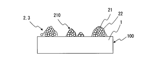
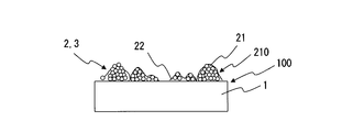
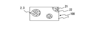
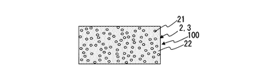
- this light guide plate applies a coating liquid 2 containing light diffusing fine particles 21 and a light-transmitting binder 22 on the back surface, front surface, or both surfaces of the light guide plate substrate 1 in a fine droplet state.
- the diffusion layer 3 is applied.
- the light diffusing fine particles 21 become aggregates 210.
- the light guide plate substrate 1 is prepared.
- a general transparent resin substrate such as polymethyl methacrylate (PMMA) resin, polystyrene resin, polycarbonate resin, or the like is preferably used.
- PMMA polymethyl methacrylate
- the large light guide plate substrate a polymethyl methacrylate resin substrate having the most excellent transparency is more preferable.
- the warp of the light guide plate substrate 1 is preferably within ⁇ 1.61 ⁇ 10 ⁇ 4 (1 / mm) in curvature (curvature of the most curved portion).
- the coating liquid 2 containing the light diffusing fine particles 21 and the translucent binder 22 is applied to the back surface or the front surface of the light guide plate substrate 1 or both surfaces (however, in this embodiment, only the front surface is referred to as a coating surface).
- the diffusion layer 3 of the present embodiment was coated with the coating solution 2 so that the coated portion and the uncoated portion were randomly arranged.
- island-shaped application portions are randomly arranged, but as shown in FIGS. 3A and 3B, island-shaped uncoated portions may be randomly arranged.
- the light guide plate used in the surface light source device means that light incident at an angle less than the critical angle repeats total reflection at the interface between the gas phase and the individual phase (hereinafter sometimes referred to as a gas interface).
- the light is propagated to a place away from the light source by using the traveling in the light guide plate.
- light is extracted by inhibiting total reflection at the interface from which light is to be extracted.
- a diffusion layer is formed in a portion where light emission is desired, but a technique for leaving the interface as it is in a portion where light emission is not desired is required. That is, it is a matter of course that a diffusion layer is formed, but a technique for intentionally leaving a gas interface is necessary.
- a spray coating method in which a coating liquid is sprayed together with gas ejection is preferable.
- a coating apparatus that does not use a plate is intended to uniformly coat the entire surface. Therefore, it is difficult to intentionally make an uncoated part. Although the uncoated portion can be formed even when the coating liquid is deficient, the control of the dripping is extremely unstable. Moreover, although unapplied parts, such as a pinhole, may occasionally occur as an unforeseen situation, it is originally uncontrollable. On the other hand, since the spray coating method sprays a coating liquid in the form of fine droplets, it has an excellent feature that it essentially includes a coating unit and a non-coating unit in a very small unit.
- the coating liquid 2 is applied to the light guide plate substrate 1 by a spray coating method. That is, as the coating apparatus, an apparatus that is excellent in flow rate stability and does not have a worry of nozzle clogging is preferable. Further, as the coating apparatus, a coating apparatus that can spray the coating liquid 2 in a uniform fine droplet state, hardly scatters the coating liquid 2 outside the planar area of the light guide plate base material 1, and has high coating efficiency is preferable. It is. Therefore, a spray coater 4 is used as a coating apparatus.
- the diffusion layer forming method is not limited to the spray coating method, and may be any spray coating method that can apply the coating liquid 2 to the light guide plate substrate 1 in a fine droplet state.
- the spray coater 4 pumps gas to the nozzle 5 and ejects it. Then, the spray coater 4 sprays the gas to be ejected onto the light guide plate substrate 1 by bringing the coating liquid 2 pumped from the storage tank 6 to the nozzle 5 by a pump or the like.
- the flow rates of the gas fed to the nozzle 5 and the coating liquid 2 are controlled by the flow rate control units 7 and 8, respectively.
- the nozzle 5 is preferably of a swirl flow type.
- the spray fluid becomes spiral and the spray angle becomes narrow. Therefore, the light diffusing fine particles 21 are likely to aggregate. Further, since the flow velocity in the normal direction when the light diffusing fine particles 21 arrive at the light guide plate substrate 1 is low, the light diffusing fine particles 21 can be attached to the light guide plate substrate 1 without breaking the aggregation of the light diffusing fine particles 21.
- the nozzle 5 is configured to be movable in the X direction and the Y direction.
- the nozzle 5 is configured to be able to spray the coating liquid 2 on the entire planar area (but may be a part) of the light guide plate substrate 1.
- the nozzle 5 is configured to be further movable in the vertical direction.
- the nozzle 5 is configured to be able to change the interval between the nozzle 5 and the light guide plate substrate 1.
- the drive mechanism of the nozzle 5 in the X and Y directions and the drive mechanism in the vertical direction are not particularly limited.
- the nozzle 5 is configured to be movable in the X / Y direction and the vertical direction, but the stage (not shown) that supports the light guide plate substrate 1 is moved in the X / Y direction and the vertical direction.
- the stage (not shown) that supports the light guide plate substrate 1 is moved in the X / Y direction and the vertical direction.
- a possible configuration is also possible.
- the gas for example, dry air or dry nitrogen can be used.
- dry nitrogen is preferably used to prevent ignition due to static electricity.
- the carrier gas may be heated to, for example, 30 ° C. or higher and 120 ° C. or lower before spraying.
- the coating liquid 2 is a mixture containing the light diffusing fine particles 21 and the translucent binder 22 as described above.
- the light diffusing fine particles 21 are members that transmit and diffuse light.
- inorganic fine particles such as silica, calcium carbonate, barium sulfate, titanium oxide, and aluminum oxide, and organic fine particles such as silicone beads, PMMA beads, MS beads, and styrene beads can be used.
- the coating liquid 2 When applying the coating liquid 2 on the surface (light emitting surface) of the light guide plate substrate 1, it is preferable to use transparent glass fine particles and transparent resin fine particles that are transmitted and scattered as the light diffusing fine particles 21.
- transparent glass fine particles and transparent resin fine particles that are transmitted and scattered as the light diffusing fine particles 21.
- white particles and pigment that are reflected and scattered as the light diffusing fine particles 21.
- the shape of the light diffusing fine particles 21 may be a true spherical shape, a spherical shape, a scale shape, an indefinite shape, or the like, and is not particularly limited.
- the average particle diameter of the light diffusing fine particles 21 is preferably 1 ⁇ m or more and 50 ⁇ m or less. If the average particle size is smaller than the lower limit value described above, the ability to diffuse light may be insufficient, or diffused light may be colored. If the average particle size is larger than the above-described upper limit, clogging may easily occur when the nozzle is used, or light diffused by the light diffusing fine particles 21 may become conspicuous as a bright spot at a portion where the coating density is low. .
- the average particle diameter is preferably 1 ⁇ m or more and 20 ⁇ m or less.
- the ratio of the light diffusing fine particles 21 to the coating solution 2 is preferably 1 wt% or more and 20 wt% or less. When the ratio is out of the above-described range, the aggregate of the light diffusing fine particles 21 may not easily be generated. If the ratio is lower than the lower limit value described above, it may be difficult to obtain a high aspect ratio and the light diffusion capability may be insufficient.
- the translucent binder 22 is a member that adheres the light diffusing fine particles 21 to the light guide plate substrate 1.
- a solvent-type adhesive for example, a thermosetting resin, an ultraviolet curable resin, or the like can be used.
- a resin component such as an acrylic pressure-sensitive adhesive that does not adhere during solvent dilution but develops adhesion after solvent drying may be used.
- the difference between the refractive index of the translucent binder 22 and the refractive index of the light diffusing fine particles 21 may be ⁇ 0.1 or less or 0.1 or more. preferable. This is because the light diffusing effect is exhibited by both the unevenness of the surface and the refractive index difference, and light can be efficiently extracted in the surface direction at a relatively short light guide distance.
- the difference between the refractive index of the translucent binder 22 and the refractive index of the light diffusing fine particles 21 is preferably ⁇ 0.1 or more and 0.1 or less. .
- the light diffusing effect is mainly exhibited only by the unevenness of the surface, and light can be gradually extracted, which is suitable for a relatively long light guide distance.
- the light diffusing fine particles 21 having a small refractive index difference may be mainly used near the light source, and the light diffusing fine particles 21 having a large refractive index difference may be mainly used at a position away from the light source.
- the light diffusion effect can be changed more dynamically in the light guide direction, and a high light extraction efficiency can be achieved at a long light guide distance.
- the translucent binder 22 preferably has a viscosity of 1 mPa ⁇ s to 100 mPa ⁇ s. If the viscosity is smaller than the lower limit value described above, leveling is likely to occur in the light guide plate substrate 1, and the light diffusion capability is reduced. If the viscosity is larger than the above-described upper limit, uneven coating tends to occur. Particularly preferably, it is 1 mPa ⁇ s or more and 20 mPa ⁇ s or less.
- the difference between the refractive index of the translucent binder 22 and the refractive index of the light guide plate substrate 1 is preferably within ⁇ 0.1. Since it is not necessary to consider the refractive reflection at the interface between the translucent binder 22 and the light guide plate substrate 1, the optical design is simple.
- the translucent binder applied to the light guide plate base material causes a leveling phenomenon. It is difficult to form a surface unevenness sufficient to cause light diffusion by the leveling phenomenon, that is, a surface unevenness sufficient to inhibit total reflection, particularly an unevenness height / an average pitch of unevenness (hereinafter sometimes referred to as an aspect ratio). , There is a possibility of flattening. Further, if the light-transmitting binder is repeatedly applied, the coating liquid in the form of fine droplets may be brought into close contact with each other due to the surface tension, and may be flattened.
- a method of applying a high-viscosity light-transmitting binder and a method of forming irregularities by adding (mixing) light diffusing fine particles to the light-transmitting binder can be considered.
- increasing the viscosity of the translucent binder tends to cause uneven coating during spraying.
- a coating liquid in which light diffusing fine particles having a large diameter are added to a light transmissive binder is applied, there is a possibility that the nozzle of the spray coater is clogged or the light diffusing fine particles are settled in the light transmissive binder.
- the translucent binder was diluted by about 1.1 to 10 times with a solvent.
- a light-diffusing fine particle having a small particle diameter of 1 ⁇ m or more and 20 ⁇ m or less is added to a low-viscosity light-transmitting binder diluted to 1 mPa ⁇ s to 20 mPa ⁇ s and sprayed between the nozzle and the light guide plate substrate.
- the diffusion layer 3 having a high light diffusing ability is obtained (see FIGS. 2A and 2B and FIGS. 3A and 3B).
- the coating liquid 2 sprayed from the nozzle 5 is in a dispersed state while the content of the solvent is large.
- the solvent dries, it reaggregates with one light diffusing fine particle 21 as a nucleus due to surface tension.
- the light diffusing fine particles 21 become cocoon-like aggregates 210.
- Aggregate 210 adheres to light guide plate substrate 1. By the way, if a large amount of solvent remains, leveling will occur after adhesion, which is not good. Therefore, aggregation may be promoted using hot air.
- the wings are crushed as shown in FIGS. 4A and 4B, and the light diffusing fine particles 21 are arranged individually, leading to a reduction in light diffusing ability.
- the interval T (FIG. 1) from the nozzle 5 to the light guide plate substrate 1.
- the interval T from the nozzle 5 to the light guide plate substrate 1 is preferably 70 mm or more and 300 mm or less.
- the solvent is not sufficiently dried. Therefore, the formation of aggregates of the light diffusing fine particles 21 hardly occurs, and the light diffusing fine particles 21 may settle in the light transmissive binder 22 and the light diffusing ability may be significantly reduced.
- the coating speed to the coating surface of the light-guide plate base material 1 is quick, an aggregate is easy to break.
- the flow rate is remarkably reduced until the coating liquid 2 reaches the coating surface of the light guide plate substrate 1. Therefore, the coating liquid 2 is not applied to the coated surface of the light guide plate substrate 1 and the amount of the coating liquid 2 scattered outward increases.
- the solvent preferably has a boiling point of 60 ° C. or higher and 200 ° C. or lower in order to stabilize reaggregation of the light diffusing fine particles 21.
- the solvent preferably has a specific gravity of 0.8 or more and 1.3 or less from the viewpoint of preventing sedimentation.
- the boiling point and specific gravity are higher than the upper limit values described above, the solvent is not sufficiently dried. For this reason, the formation of aggregates of the light diffusing fine particles 21 may hardly occur.
- the boiling point or specific gravity is lower than the lower limit value described above, many have relatively low viscosities. Therefore, there may be a problem that the light diffusing fine particles 21 are likely to settle.
- the boiling point is preferably 120 ° C. or higher and 170 ° C. or lower. Further, the boiling point is more preferably 130 ° C. or higher and 160 ° C. or lower.
- the mixing ratio of the mixture of the light diffusing fine particles 21 and the light transmissive binder 22 with respect to the solvent is preferably 2 wt% or more and 50 wt% or less.
- the mixing ratio is more preferably 3 wt% or more and 30 wt% or less.
- the light guide plate base material 1 on which the coating liquid 2 is spray-coated is dried by natural air drying or hot air.
- the translucent binder 22 is made of an ultraviolet curable resin
- the translucent binder 22 is cured by irradiating ultraviolet rays in the subsequent steps.
- the plurality of light diffusing fine particles 21 form a cocoon-shaped aggregate 210 with one light diffusing fine particle 21 as a nucleus.
- the aggregate 210 adheres to the coated surface of the light guide plate substrate 1.
- the aggregate 210 has a high aspect ratio and forms the diffusion layer 3 having a fine pattern.
- the coating liquid 2 when the coating liquid 2 is applied to the light guide plate base material 1 without creating a plate or a mold as in the prior art, the diffusion layer 3 having excellent light diffusing ability of a fine pattern can be easily and inexpensively formed. it can. Moreover, even if the coating liquid 2 is applied over the light guide plate substrate 1 by spray coating, the light diffusing fine particles 21 adhere in an agglomerated state and are difficult to flatten. Therefore, the coating liquid 2 can be satisfactorily applied to the light guide plate substrate 1 by a spray coating method.
- the ratio R between the flat area occupied by the aggregate on the coated surface of the light guide plate substrate 1 and the coating area of the coating liquid 2 is 0.1% or more and 70% or less. If the ratio R is less than the lower limit value described above, the light diffusion capability of the light guide plate 100 may be insufficient. If the ratio R is larger than the above-described upper limit value, the light diffusing ability of the light guide plate 100 becomes too large, and when the light guide length L (FIG. 5) is long, the amount of emitted light at a position away from the light source may be insufficient. is there.
- the diffusion layer 3 is applied by applying the coating liquid 2 containing the light diffusion fine particles 21 and the light transmissive binder 22 to the surface of the light guide plate substrate 1.
- the light diffusing fine particles 21 are aggregates 210.
- the ratio R between the flat area occupied by the aggregates 210 on the coated surface of the light guide plate substrate 1 and the coating area of the coating liquid 2 is 0.1% or more and 70% or less.
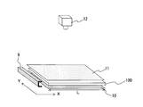
- the light guide plate 100 includes a line light source 9 such as an LED array installed at one end, a diffuse reflection film 10 installed on the back side, and a diffusion film installed on the front side. 11 constitutes a surface light source device.
- the aggregate 210 of the plurality of light diffusing fine particles 21 has a high aspect ratio and forms the diffusion layer 3 having a fine pattern. Therefore, when the coating liquid 2 is applied to the light guide plate base material 1 without creating a plate or a mold as in the prior art, the diffusion layer 3 having excellent light diffusing ability of a fine pattern can be easily and inexpensively formed. it can.
- a light-transmitting binder that does not contain the light diffusing fine particles 21 may be applied between the light guide plate substrate 1 and the diffusion layer 3 to the entire upper surface region of the light guide plate substrate 1 with a uniform thickness.
- the translucent binder functions as an antistatic layer, a hard coat layer, or the like.
- the coating area ratio S between the coating area of the coating liquid 2 (the flat area of the diffusion layer) and the area of the coating surface of the light guide plate substrate 1 is preferably 5% or more and 95% or less. If the coating area ratio S is less than the lower limit value described above, the light diffusion ability of the light guide plate 100 may be insufficient. If the coating area ratio S is larger than the above-described upper limit value, light absorption by the translucent binder 22 cannot be ignored and the brightness may be insufficient.
- the number of light diffusing fine particles 21 contained in one aggregate 210 is preferably 10 or more and 10,000 or less. If the number is less than the lower limit value described above, the light diffusion capability of the light guide plate 100 may be insufficient. When the number is larger than the above-described upper limit value, appearance defects such as unevenness, rough feeling, and bright spots are likely to occur.
- the coated surface of the light guide plate substrate 1 is composed of monodispersed light diffusing fine particles 21 and less than 10 light diffusing fine particles 21 in addition to the aggregates in which the number of light diffusing fine particles 21 is 10 or more and 10,000 or less.
- Aggregates 210 may be present. In this case, it is preferable that the monodispersed light diffusing fine particles 21 and the aggregate 210 composed of less than 10 light diffusing fine particles 21 are less than 20% of the total number of light diffusing fine particles.
- the number of the light diffusing fine particles 21 contained in the aggregate 210 can be counted by observation with an optical microscope or a laser microscope of about 300 to 1000 times. Moreover, after collecting the aggregate 210 and removing the translucent binder 22, it can be counted by observation with an optical microscope or the like.
- the light diffusing ability is insufficient with a single application, it may be overcoated.
- the high aspect ratio of the aggregate 210 is maintained even if the aggregates of the light diffusing fine particles 21 are adhered and integrated by recoating. Therefore, there is an advantage that the light diffusion ability is high and it is difficult to cause the appearance defect.
- the difference between the refractive index of the aggregate and the refractive index of the translucent binder is preferably 0.001 or more and 0.5 or less.
- the light diffusing capacity is based on the difference in refractive index of a substance that has a refractive index different from that of a substantially transparent material, the volume of the substance, the volume concentration of the substance, the shape of the substance (a regular or irregular shape such as a true sphere), and fine irregularities on the surface It changes by etc.
- the difference in refractive index is smaller than the lower limit value described above, it is difficult to obtain an effect of uniforming illuminance due to low refractive scattering properties.
- the difference in refractive index is larger than the above-described upper limit, reflection at the interface (gas interface) increases, and it is difficult to obtain an effect of uniforming illuminance when the light guide length is relatively long, for example, 300 mm or more.
- the arithmetic average surface roughness of the fine irregularities in the aggregate 210 is preferably 0.01 ⁇ m or more and 10 ⁇ m or less.
- the arithmetic average surface roughness is smaller than the above-described lower limit, the reflection / scattering property is small and the entire surface tends to be dark.
- the arithmetic average surface roughness is larger than the above-described upper limit value, it is difficult to obtain an effect of uniform illuminance such that the reflection / scattering element is physically large and the vicinity of the light source is locally bright.
- Embodiment 2 of the present invention will be described below.
- the light guide plate and the light guide plate manufacturing method of the present embodiment are substantially the same as the light guide plate and light guide plate manufacturing method of the first embodiment, but as the brightness of the light guide plate becomes substantially uniform,
- the ratio R between the flat area occupied by the aggregates on the coated surface of the light guide plate substrate and the coated area of the coating solution, or the coating area ratio S between the coated area of the coating solution and the coated surface area of the light guide plate substrate was increased. . That is, as the distance from the light source increased, the coating density of the light diffusing fine particles was increased.
- the backlight is also required to be increased in size. That is, the light guide length L (FIG. 5) needs to be increased.
- the light guide length L (FIG. 5) needs to be increased.
- the patterning of the diffusion layer is inadequate, or even if the pattern can be designed, but the printing accuracy is inferior, only the edge near the light source in the light guide plate is bright and the central part is dark, that is, essential as a light guide plate There is a problem that the performance is not satisfied and a problem that luminance unevenness occurs on the light exit surface. From these viewpoints, it is necessary to refine the pattern of the diffusion layer and to accurately form a pattern arrangement that is rougher as the diffusion portion is closer to the light source and becomes denser as the distance from the light source is increased. “Near the light source” refers to a portion located closest to the light source in the effective light emitting portion of the light guide plate.
- “in the vicinity of the light source” means an end portion on the side where the light source is installed.
- the “position farthest from the light source” refers to a part of the effective light emitting portion of the light guide plate that is farthest from the light source. That is, the “position farthest from the light source” means an end on the side facing the end on the side where the light source 9 is installed in the case of the light guide plate shown in FIG.
- the coating liquid 2 is applied to the light guide plate substrate 1 by a spray coating method in substantially the same manner as in the first embodiment.
- a plurality of light diffusing fine particles 21 are aggregated in the shape of a hull with one light diffusing fine particle 21 as a nucleus.
- the gradation distribution pattern arrangement is such that the aggregates 210 thus aggregated become denser as they move away from the light source.
- the LED array light source 9 was installed in the left end of the light-guide plate 100 which apply
- the coated surface of the light guide plate substrate 1 was set as the exit surface side.
- the diffuse reflection film 10 was installed on the back side of the coated surface.
- a diffusion film 11 was installed on the front surface of the coating surface.
- a sidelight type backlight was produced.
- the surface luminance measuring device 12 was used to measure from above the sidelight type backlight.
- the side arranged in the Y direction in the light guide plate substrate 1 is the first side referred to in the present invention.
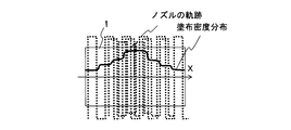
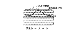
- ⁇ Coating width by scanning the nozzle 5 once in the Y direction is about 50 mm.
- the central portion has a distribution similar to the Gaussian distribution in which the coating density of the light diffusion fine particles 21 is high and gradually decreases toward the outside.
- unevenness occurs in the coating density of the light diffusing fine particles 21, and unevenness in brightness is generated in the luminance distribution as shown in FIG.
- the relative luminance decreases as the distance from the light source 9 increases.
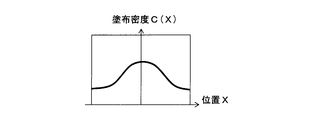
- the light diffusion performance of the light guide plate 100 to which the coating liquid 2 is applied is proportional to the application density of the light diffusion fine particles 21 on the surface of the light guide plate substrate 1. Therefore, the coating liquid 2 may be spray-coated so that the coating density of the light diffusing fine particles 21 is low on the light source side and high on the far side of the light source. The method is described below.
- the figure shows a gradation distribution in which the density is high and the coating density of the light diffusing fine particles 21 is lowered on both sides (that is, the end faces A and B sides) of the central portion.
- the light guide plate substrate 1 is assumed to be a light guide plate substrate in which line light sources such as LED arrays are installed on both end faces A and B. 7A and 7B, the coating amount of the coating liquid 2 is kept constant, and the nozzle 5 is scanned in the Y direction at a constant speed. From the end face A side, the feed pitch in the X direction of the nozzle 5 starts from 10 mm so as not to be uneven. The coating liquid 2 is applied around the central portion of the light guide plate substrate 1 so that the feed pitch is gradually changed in a narrow manner. As a result, a complete gradation distribution without discontinuities is realized.
- the spray coating method has a very high degree of freedom in achieving gradation distribution.
- 8A and 8B summarize the parameters and various coating methods when the coating liquid 2 is applied.
- linear light sources such as LED arrays are installed on the left and right end faces A and B of the light guide plate substrate 1.
- the ratio R or the coating area ratio S is increased as the distance from the light source increases in order to make the in-plane luminance distribution constant. That is, the coating density of the light diffusing fine particles 21 at both ends of the light guide plate substrate 1 is lowered, and the coating density of the light diffusing fine particles 21 is increased around the central portion.
- the other conditions are set so that the light diffusing fine particles 21 can be satisfactorily aggregated 210 and adhere to the light guide plate substrate 1.
- the X direction is the length direction of the light guide plate substrate 1, that is, the light guide direction
- the Y direction is the width dimension direction of the light guide plate substrate 1.
- the scanning direction of the nozzle 5, the scanning speed of the nozzle 5, the feed pitch of the nozzle 5, the coating amount of the coating liquid 2 per unit time, and the like can be considered. Any one or more of these parameters are controlled and the other parameters are kept constant.
- the coating method (1) shown in FIG. 8B applies the coating liquid 2 as follows.
- positioned in the Y direction in the light-guide plate base material 1 becomes a 1st edge
- the coating liquid 2 is uniformly applied to the whole or a part of the transparent light guide plate substrate 1 with all parameters being constant (FIG. 9A).
- the coating solution 2 is applied uniformly and uniformly around the central portion. That is, the application of the coating liquid 2 is repeated around the central portion with all parameters being constant.
- the said ratio R or the coating area ratio S is made high as it leaves
- This situation is shown in FIG. 9A, but it is inevitable that a finite step is always generated at the boundary of overpainting. Therefore, it is preferable that the coating amount of the coating liquid 2 is as small as possible and the scanning speed of the nozzle 5 is as fast as possible.
- the coating liquid 2 so as to reduce the coating density of the light diffusing fine particles 21 in one uniform coating as much as possible and to increase the number of repeated coatings.
- multi-layer overcoating may be performed while appropriately adjusting the coating amount of the coating liquid 2, the scanning speed of the nozzle 5, the feed pitch of the nozzle 5, and the like.
- the coating method (2) shown in FIG. 8B is a coating method in which only the feed pitch in the X direction is continuously changed and other parameters are constant. Also in the coating method (2), the side arranged in the Y direction in the light guide plate substrate 1 is the first side referred to in the present invention.
- the coating density of the applied light diffusing fine particles 21 increases and decreases in inverse proportion to the feed pitch of the nozzles 5. Therefore, the feed pitch is continuously increased or decreased so as to have an inversely proportional relationship of the desired gradation distribution function (FIG. 9B). That is, the feed pitch of the nozzles 5 is widened at both ends of the light guide plate substrate 1, and the feed pitch of the nozzles 5 is narrowed around the center.
- this coating method (2) a desired gradation distribution can be obtained and the productivity is high even if the coating liquid 2 is not overcoated. Moreover, since it is a complete gradation distribution in which discontinuities do not occur, a high-quality surface light source device without luminance unevenness can be obtained.
- the coating method (3) shown in FIG. 8B is a coating method in which only the scanning speed is changed every time the nozzle 5 is scanned and other parameters are constant. Also in the coating method (3), the side arranged in the Y direction in the light guide plate substrate 1 is the first side referred to in the present invention.
- the coating density of the light diffusing fine particles 21 is inversely proportional to the scanning speed of the nozzle 5. For this reason, as shown in FIG. 9C, the scanning speed for each scanning of the nozzle 5 is continuously changed so as to have an inversely proportional relationship of a desired gradation distribution. That is, both ends of the light guide plate substrate 1 increase the scanning speed of the nozzle 5 and decrease it around the center.
- This coating method (3) is also preferable in terms of both productivity and brightness unevenness.
- the coating method (4) shown in FIG. 8B is a coating method in which only the coating flow rate of the coating liquid 2 is changed every time the nozzle 5 is scanned, and other parameters are constant.
- the side arranged in the Y direction in the light guide plate substrate 1 is the first side referred to in the present invention. That is, as the nozzle 5 is sent at a predetermined pitch from the end surface A side to the central portion, the coating amount of the coating liquid 2 is increased, and as the nozzle 5 is fed from the central portion to the end surface B side where the light source is installed, the coating liquid 2 is applied. Reduce the amount ( Figure 9D).
- this coating method (4) is also of high productivity and uneven brightness. Preferred on both sides.
- the coating amount of the coating liquid 2 is excessive, and the aggregates 210 of the light diffusing fine particles 21 are settled in the translucent binder 22.
- the coating amount of the coating liquid 2 is set to an appropriate amount. Further, as the nozzle 5 is sent from the central portion to the end face B side, the coating amount of the coating liquid 2 is excessively increased again to cause the aggregates 210 of the light diffusing fine particles 21 to settle in the translucent binder 22. By applying in this way, the same effect can be obtained.
- the coating method (5) shown in FIG. 8B is a coating method in which the scanning for moving the nozzle 5 in the X direction is repeated at a predetermined feed pitch in the Y direction. More specifically, the scanning speed is continuously changed during the scanning of the nozzle 5, and other parameters are constant.
- the side arranged in the X direction in the light guide plate substrate 1 is the first side referred to in the present invention.
- the scanning speed of the nozzle 5 in the X direction is continuously changed so that the inverse relationship of the desired gradation distribution function is obtained. That is, in the scanning of the nozzle 5 in the X direction, the scanning speed of the nozzle 5 is increased at both ends of the light guide plate substrate 1 and is decreased around the center (FIG. 9E).
- This coating density of the light diffusing fine particles 21 at both ends near the light source of the light guide plate substrate 1 is lowered, and the coating density of the light diffusing fine particles 21 around the central portion far from the light source is increased.
- This coating method (5) is also preferable in terms of both productivity and luminance unevenness.
- the coating method (6) shown in FIG. 8B is also a coating method in which the scanning for moving the nozzle 5 in the X direction is repeated at a predetermined feed pitch in the Y direction. More specifically, the application amount of the application liquid 2 is continuously changed during the scanning of the nozzle 5, and the other parameters are constant. Also in the coating method (6), the side arranged in the X direction in the light guide plate substrate 1 is the first side referred to in the present invention. Specifically, in the scanning of the nozzle 5 in the X direction, the application amount of the coating liquid 2 is small at both ends of the light guide plate substrate 1, and a large amount is ejected around the center (FIG. 9F).
- This coating method (6) is also preferable in terms of both productivity and luminance unevenness. Further, when the coating amount of the coating liquid can be varied at high speed, a desired gradation distribution can be easily realized by this coating method (6).
- the application amount of the coating liquid 2 is excessive at both ends of the light guide plate substrate 1 to cause the aggregates 210 of the light diffusing fine particles 21 to settle in the translucent binder 22, and the coating amount of the coating liquid 2 is set at the central portion. Even if the amount is appropriate, the same effect can be obtained.
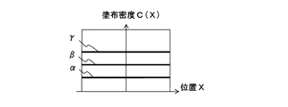
- the light-diffusing fine particles 21 and the light-transmitting binder 22 and, if necessary, the coating liquid 2 containing a solvent are uniformly applied to the light guide plate substrate 1 at a feed pitch that does not cause uneven brightness, for example, a feed pitch of 10 mm.
- the light guide plate coated uniformly in this way is manufactured by changing the application amount of the coating liquid 2 and the scanning speed of the nozzle 5 (three types ⁇ to ⁇ in the illustrated example).
- FIG. 10A shows the coating density of the light diffusing fine particles 21 on the manufactured light guide plates ⁇ to ⁇ .
- the six coating methods (1) to (6) shown in FIG. 8B are preferably used.
- the feed pitch ⁇ X (X) is the feed pitch ⁇ Y (X) of the nozzle 5 in the Y direction.
- the coating methods (1) to (6) shown in FIG. 8B may be applied as follows. However, the X coordinate at the left end of FIG.
- the application amount of the coating liquid 2 at the left end is F 0 , V Y0 , ⁇ X 0 , and the target application density of the light diffusion fine particles 21 at the left end is C 0 .
- the target application density C (X) of the light diffusing fine particles 21 at the position X in FIG. 10C or FIG. 10D may be applied while determining parameters as follows. At this time, in order to prevent uneven coating, it is necessary to set the feed pitch of the longest nozzle to be 10 mm as described above.
- a diffusion layer is applied by applying a coating liquid containing light diffusing fine particles and a light-transmitting binder to the surface of the light guide plate substrate 1.
- the light diffusing fine particles are aggregated.
- the ratio of the flat area occupied by the aggregates on the coated surface of the light guide plate substrate 1 and the coating area of the coating liquid is 0.1% or more and 70% or less. Therefore, also in this embodiment, the aggregate of a plurality of light diffusing fine particles has a high aspect ratio and forms a fine pattern diffusion layer. Therefore, when a coating solution is applied to the light guide plate substrate 1 without creating a plate or a mold as in the prior art, a diffusion layer excellent in light diffusing ability of a fine pattern can be formed easily and inexpensively.
- the spray coating method can be applied to the front and back surfaces of the light guide plate substrate 1 and also to both sides without any problem.
- a one-dimensional gradation distribution in the X direction is realized for the front surface by the coating methods (1) to (6), and a one-dimensional gradation in the Y direction is performed for the back surface by the coating methods (1) to (6). It is also possible to realize gradation distribution and manufacture a three-sided light source type and a four-sided light source type light guide plate.
- a wide diffuse reflection capability range that is, a coating density range of the light diffusing fine particles 21 is required. It is generally difficult to increase or decrease the coating density of the light diffusion fine particles 21 to achieve a light diffusion performance of 5 to 10 times or more.
- the gradation distribution is applied by the coating methods (1) to (6) so that the coating density of the light diffusing fine particles 21 is uniformly sprayed on the back surface, and the surface is supplemented with insufficient light diffusion performance. Realize. Thereby, it may be easy to manufacture a gradation light guide plate with high luminance efficiency and uniform brightness. The present invention can be effectively applied even in such a case.
- the spray coating method can be easily applied to a large light guide plate having a size of 50 inches or more, for example.
- Injection molding, press molding, dot printing, etc. all require large precision molds and screen plates, as well as large facilities and high investment costs.
- in the ink jet printing method a large amount of investment is required to support a large format.
- the spray coating method of the present invention is applied to a large light guide plate with inexpensive equipment.
- it is suitable for a light guide plate having a light guide length L of 900 mm or more.
- the ratio between the illuminance in the vicinity of the light source and the illuminance at the position farthest from the light source is 0.8 or more and 1.2 or less.
- the coating density of the light diffusing fine particles applied to the surface can be lowered as a whole. Therefore, it is beneficial in some cases. For example, as described above, light diffusion performance is insufficient only by surface coating. Further, for example, in the case of a thick and short light guide plate, the light guide light incident from the light source may reach the opposite end surface before sufficiently colliding with the diffuse reflection surface, and the surface light emission may not be sufficiently performed. In that case, it is possible to emit light effectively by slightly dispersing the diffusion portion in the light guide plate. The present invention is also suitably used for such applications.
- the coating area ratio S1 in the vicinity of the light source is 5% or more and 50% or less
- the coating area ratio S2 at the position farthest from the light source is 20% or more and 95% or less
- the (2 ⁇ / 360) ⁇ 60 rad gloss value GS1 of the coated surface of the light guide plate substrate in the vicinity of the light source is 40 or more and 90 or less, and (2 ⁇ of the coated surface of the light guide plate substrate 1 at the position farthest from the light source.
- / 360) ⁇ 60 rad gloss value GS2 may be 10 or more and 60 or less, and GS2> GS1.
- the haze value H1 in the surface direction in the vicinity of the light source is 5% or more and 30% or less
- the haze value H2 at the position farthest from the light source is 10% or more and 40% or less
- H2> H1 may be satisfied.
- Embodiment 3 of the present invention will be described below.
- the light guide plate and the light guide plate manufacturing method of the present embodiment are substantially the same as the light guide plate and light guide plate manufacturing method of the second embodiment, except that the light diffusing fine particles have a two-dimensional gradation distribution. Therefore, only the differences will be described in detail.
- FIG. 11 schematically shows a two-dimensional gradation distribution on the assumption that line light sources are installed on the four sides of the light guide plate 100. That is, M in FIG. 11 indicates a portion where the coating density of the light diffusing fine particles is substantially equal by connecting with lines. N in FIG. 11 indicates the distribution in the X direction of the coating density of the light diffusing fine particles. P in FIG. 11 indicates the distribution in the Y direction of the coating density of the light diffusing fine particles. If the target gradation distribution can be expressed by C (X, Y), it can be manufactured by using coating methods (1) to (6) alone or in combination.
- the coating method (1) it is possible to carry out the repeated coating along the line (a) in FIG. In order to prevent luminance unevenness and luminance steps at the boundary of overcoating, a sufficiently large number of overcoating operations are required.
- the application method (3) can be applied by continuously changing the scanning speed during one scanning of the nozzle in the Y direction. That is, the nozzle scanning speed in the Y direction may be scanned according to the following formula.
- V Y (X, Y) V Y0 ⁇ C 0 / C (X 0 + ⁇ X, Y), F and ⁇ X are constant
- the coating amount of the coating solution may be ejected according to the following formula.
- F (X, Y) F 0 ⁇ C (X 0 + ⁇ X, Y) / C 0 , V Y and ⁇ X are constant.
- a two-dimensional gradation distribution can also be realized by combining the coating methods (5) and (6). That is, the nozzle may be scanned in the X direction according to the following formula.
- V X (X, Y) V X0 ⁇ C 0 / C (X, Y), F and ⁇ Y are constant
- F (X, Y) F 0 ⁇ C (X, Y) / C 0 , V X and ⁇ Y Is constant
- the coating method (2) it is possible to realize a two-dimensional gradation distribution by changing the nozzle scanning speed and the coating liquid application amount during one nozzle scanning in the Y direction.
- the two-dimensional gradation distribution is not limited to a four-side light source, but may be an orthogonal two-light source or a three-side light source, and includes a case where the application density of the light diffusing fine particles is finely adjusted in the peripheral portion of the end face. .
- a plurality of nozzles 5 are arranged in parallel at equal intervals in the Y direction, that is, in a direction substantially orthogonal to the scanning direction.
- the plurality of nozzles 5 are scanned in the X direction.
- a configuration may be adopted in which a plurality of nozzles 5 are arranged in parallel at equal intervals in the X direction and the plurality of nozzles 5 are scanned in the Y direction.
- the application time can be significantly shortened by using a multi-nozzle. It is conceivable that the interval between the adjacent nozzles 5 and 5 needs to be sufficiently wide so as not to interfere with each other at the time of application. In some cases, the adjacent nozzles may be shifted in the X direction and arranged alternately.
- These plural nozzles 5 are individually or commonly controlled, and spray coating the coating liquid onto the light guide plate substrate 1.
- the nozzles 5 arranged in parallel by applying the coating method (5) or (6) are scanned once in the X direction. At this time, each nozzle 5 has the same flow rate.
- a sufficiently small Y-direction feed pitch that does not cause luminance unevenness for example, 10 mm is shifted in the Y direction, and scanning is performed in the X direction by the coating method (5) or (6). By scanning this for the nozzle interval, it can be applied uniformly over the entire surface.
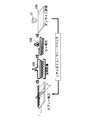
- FIG. 13 shows a prototype / manufacturing process in the case where the light transmissive binder is an ultraviolet curable type and spray coating is performed using a coating solution of light diffusing fine particles in combination with a solvent.
- the coating liquid 2 is spray-coated on the light guide plate substrate 1, the solvent is dried by warm air or the like.
- the light-transmitting fine particles are permanently adhered to the surface of the light guide plate substrate by irradiating ultraviolet rays to cure the light-transmitting binder.
- the luminance distribution is immediately measured and evaluated. If the desired uniformity cannot be obtained, fine adjustment is made to each parameter and coating is performed again. If this is repeated as necessary, the gradation distribution of the light diffusing fine particles can be easily realized in a short time.
- both the one-dimensional gradation distribution and the two-dimensional gradation distribution of the light diffusing fine particles do not require a mold or a printing plate, and can be prototyped and produced immediately from the design.
- the gradation distribution of the optimal light diffusing fine particles with uniform brightness so that the light from the light source can be emitted efficiently and uniformly forwards varies depending on the size, shape, plate thickness, light source position, etc. of the light guide plate substrate.
- the method of the present invention is suitably applied to the production of such a variety and variety.
- the aggregates 210 of the light diffusing fine particles 21 are randomly attached to the light guide plate substrate 1.
- the ratio R of the flat area occupied by the aggregates 210 on the coated surface of the light guide plate substrate 1 and the coating area of the coating solution 2 or the coating area of the coating solution 2 and the light guide plate base The coating area ratio S to the area of the coating surface of the material 1 is increased.
- the ratio of the flat area occupied by the aggregate 210 on the coated surface of the light guide plate substrate and the coating area of the coating liquid 2 satisfies the requirement of 0.1% or more and 70% or less
- the aggregate 210 of the light diffusing fine particles 21. May be attached to the light guide plate substrate 1 substantially uniformly. That is, the ratio S2 / S1 between the coating area ratio S1 in the vicinity of the light source 9 and the coating area ratio S2 at the position farthest from the light source 9 is configured to be 80% or more and 120% or less.
- the ratio of the flat area occupied by the aggregates 210 on the coated surface of the light guide plate substrate 1 and the coating area of the coating liquid 2 is 0.1% or more and 70% or less, but this is not restrictive.
- the coating density of the light diffusing fine particles should be low at the part close to the light source, and the coating density of the light diffusing fine particles should be high at the part far from the light source.
- the light diffusing fine particles 21 are aggregates, but this is not restrictive. That is, the light diffusing fine particles 21 may not be aggregated.
- spray coating conditions such as light diffusion fine particles, a light-transmitting binder, a solvent, and a distance between the light guide plate substrate and the nozzle are appropriately controlled and selected.
- the coating liquid 2 may be applied in a polka dot shape (FIG. 14).
- the entire surface may be covered with the coating liquid 2 (FIG. 15).
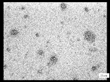
- 16A and 16B are photomicrographs of a state in which a coating liquid of MS fine particles, an ultraviolet curable translucent binder, and a solvent is spray-coated on a PMMA substrate and cured.
- the part represented as a bubble is a light diffusing fine particle. Since the light diffusing fine particles adhering to the coated surface of the light guide plate base material 1 each become a diffusing portion, a fine diffusing portion can be easily formed. Further, since the light diffusing fine particles are always applied randomly, the generation of moire can be suppressed.
- Example 1 An acrylic resin sheet having a length (length in the light guiding direction) of 1200 mm, a width of 1000 mm, and a thickness of 8 mm is placed as a light guide plate base material on a regular board (stage), and applied from above the acrylic resin sheet by a nozzle of a spray coater. The liquid was sprayed.
- the coating liquid is resin fine particles (refractive index 1.56, average particle size 3 ⁇ m ⁇ ) as light diffusing fine particles, acrylic UV curable resin as a light transmissive binder, and a ketone solvent as a diluting solvent so that the solid content is 5 wt%. It is a diluted mixed solution. This coating solution was spouted with nitrogen gas.
- the nozzle was sprayed while being moved in the plane direction of the light guide plate substrate (that is, the X and Y directions). Specifically, the coating amount is changed according to the length direction of the light guide plate base material (that is, the X direction), and is applied once at a nozzle feed pitch of 10 to 40 mm depending on the location so as to be applied most at the center in the X direction. -8 times of overcoating were performed.
- the distance between the light guide plate substrate 1 and the nozzle 5 is 100 to 200 mm
- the coating amount of the coating liquid 2 is 0.5 to 4.0 gr / min
- the scanning speed of the nozzle 5 is 200 to 400 mm / sec. did.
- the surface state by coating became gloss 85 near the light source and gloss 15 at a position of 600 mm in the length direction.
- a light source in which white LEDs are linearly arranged at both ends of the light guide plate base material is installed, a white diffuse reflection sheet is laminated on the back side of the light guide plate base material, and a light diffusion film is laminated on the coating surface to be the front side, A sidelight type backlight was produced.
- Example 2 On the surface plate (stage), a transparent PMMA light guide plate substrate having the same size as that of Example 1 was placed, and the coating solution was applied from above by a nozzle as shown in FIG. At this time, by the coating method (1) shown in FIG. 8B, uniform application was first performed with the scanning direction as the Y direction and the X direction feed pitch as 10 mm.
- the coating solution is MS resin cross-linked particles (average particle size 3 ⁇ m, solid reconstitution residual concentration excluding solvent 10 wt%) as light diffusing fine particles, urethane-based UV curable resin as translucent binder, and PGMAC (propylene glycol monomethyl as diluting solvent). It is a mixed solution diluted with ether acetate) to a solid content of 20 wt%. This coating solution was spouted with nitrogen gas.
- the distance between the light guide plate substrate and the nozzle was 150 mm
- the coating amount of the coating liquid was 1 mL / min in terms of solution
- the nozzle scanning speed was 150 mm / min.
- the coating width was about 50 mm.
- the coating liquid was applied to the entire surface of the light guide plate substrate while feeding the nozzle in the Y direction at intervals of 10 mm in the X direction.
- blank scanning was started 20 mm before the light guide plate substrate.
- the light guide plate base material was scanned to a point exceeding 20 mm even at the end of coating on the other end surface (upper end surface in FIG. 5) arranged in the X direction.
- coating was performed from 20 mm before the light guide plate substrate.
- the other end face arranged in the Y direction (the end face on the right side in the paper surface of FIG. 5) is coated over the light guide plate base material by 20 mm, and coating unevenness at the direction changing portion of the nozzle is applied to the base body. It was carried out not to enter.
- a sidelight-type backlight was produced in the same manner as in Example 1 with the coated surface of the light guide plate as the emission side.
- an eight-level luminance step was visually recognized, but a uniform light guide plate that was sufficiently acceptable was obtained.
- Example 3 Coating was started under the same conditions as in Example 2, but a method of changing the scanning speed in the Y direction semi-continuously by the X direction feed pitch in the coating method (3) was used.
- the coating distribution of the light diffusing fine particles on the uniformly coated light guide plate substrate 1 with an X direction feed pitch of 10 mm is C 0
- the scanning speed 150 mm / min of the nozzle 5 in the Y direction is V.
- V Y (X) V Y0 ⁇ C 0 / C (X 0 + ⁇ X)
- the light guide plate and the light guide plate manufacturing method of the present invention can be used as a surface light source device that emits light from the back surface of a liquid crystal display panel, a signboard, or the like, a so-called backlight device light guide plate and a light guide plate manufacturing method.
Landscapes
- Physics & Mathematics (AREA)
- General Physics & Mathematics (AREA)
- Optics & Photonics (AREA)
- Engineering & Computer Science (AREA)
- Manufacturing & Machinery (AREA)
- Nonlinear Science (AREA)
- Planar Illumination Modules (AREA)
- Mathematical Physics (AREA)
- Chemical & Material Sciences (AREA)
- Crystallography & Structural Chemistry (AREA)
- Light Guides In General And Applications Therefor (AREA)
- Optical Elements Other Than Lenses (AREA)
Abstract
Description
即ち、本発明に係る導光板及び導光板の製造方法は、以下のような構成及び工程とした。
本発明の実施形態1を以下に説明する。本発明に係る導光板は、液晶表示パネルや看板などの背面から光を照射するバックライト装置の構成部材の一つである。導光板の端面に光源が配置される。
光拡散微粒子21の平均粒径は、1μm以上50μm以下が好ましい。当該平均粒径が前述した下限値より小さいと、光を拡散する能力が不足したり、拡散光が着色したりする恐れがある。当該平均粒径が前述した上限値より大きいと、ノズルを使用した際に詰まり易くなったり、塗布密度が小さい部分で当該光拡散微粒子21による拡散光が輝点となって目立ったりする恐れがある。特に当該平均粒径は、1μm以上20μm以下が好ましい。
透光性バインダ22の屈折率と導光板基材1の屈折率との差が±0.1以内であることが好ましい。透光性バインダ22と導光板基材1との界面での屈折反射を考慮しなくて良いので光学設計が簡単である。
本発明の実施形態2を以下に説明する。本実施形態の導光板及び導光板の製造方法は、実施形態1の導光板及び導光板の製造方法と略同様であるが、導光板の輝度が略均一となるように、光源から離れるにつれて、導光板基材の塗工面における凝集体が占める平面積と塗布液の塗布面積との比率R又は塗布液の塗布面積と導光板基材の塗工面の面積との塗工面積比率Sを高くした。すなわち、光源から離れるにつれて、光拡散微粒子の塗布密度を高くした。
なお、このような多層重ね塗りについては、塗布液2の塗布量、ノズル5の走査速度、ノズル5の送りピッチなどを変えて適宜調整しながら、重ね塗りを実施しても良い。
すなわち、ノズル5を所定のピッチで、端面A側から中央部に送るにつれ、塗布液2の塗布量を多くし、中央部から光源が設置される端面B側に送るにつれ、塗布液2の塗布量を少なくする(図9D)。
詳細には、ノズル5のX方向への走査において、導光板基材1の両端部で塗布液2の塗布量を少なく、中央部周辺で多く噴出する(図9F)。
塗工法(1):F、VY、ΔX及び重ね塗り段数などを適宜選定して実施
塗工法(2):ΔX(X)=ΔX0×C0/C(X0+ΣΔX)、F及びVYは一定
塗工法(3):VY(X)=VY0×C0/C(X0+ΣΔX)、F及びΔXは一定
塗工法(4):F(X)=F0×C(X0+ΣΔX)/C0、VY及びΔXは一定
塗工法(5):VX(X)=VX0×C0/C(X)、F及びΔYは一定
塗工法(6):F(X)=F0×C(X)/C0、VX及びΔYは一定
なお、必要に応じて、塗工法(1)乃至(6)を併用しても可能である。
本発明の実施形態3を以下に説明する。本実施形態の導光板及び導光板の製造方法は、実施形態2の導光板及び導光板の製造方法と略同様であるが、光拡散微粒子を2次元グラデーション分布としている点が相違する。そのため、相違部分のみを詳細に説明する。
VY(X、Y)=VY0×C0/C(X0+ΣΔX、Y)、F及びΔXは一定
F(X,Y)=F0×C(X0+ΣΔX、Y)/C0、VY及びΔXは一定
VX(X、Y)=VX0×C0/C(X、Y)、F及びΔYは一定
F(X、Y)=F0×C(X、Y)/C0、VX及びΔYは一定
常盤(ステージ)上に導光板基材として、長さ(導光方向の長さ)1200mm、幅1000mm、厚み8mmのアクリル樹脂シートを置き、当該アクリル樹脂シートの上方から、スプレーコータのノズルによって塗布液を噴霧した。塗布液は、光拡散微粒子として樹脂微粒子(屈折率1.56、平均粒径3μmφ)、透光性バインダとしてアクリル系紫外線硬化樹脂、希釈溶媒としてケトン系溶剤にて固形分5wt%となるように希釈した混合溶液である。この塗布液に窒素ガスを同伴させて噴出させた。
次いで導光板基材の両端部に白色LEDを線状に配置した光源を設置し、当該導光板基材の裏面側に白色拡散反射シート、表面側となる塗工面に光拡散フィルムを積層し、サイドライト式バックライトを作製した。
定盤(ステージ)の上に、実施例1と等しいサイズの透明PMMA導光板基材を置き、図7のように、上方からノズルによって塗布液を塗布した。このとき、図8Bに示す塗工法(1)により、走査方向をY方向として、X方向送りピッチ10mmピッチとしてまず均一塗布を実施した。塗布液は、光拡散微粒子としてMS樹脂の架橋粒子(平均粒径3μm、溶媒を除く固形分換残濃度10wt%)、透光性バインダとしてウレタン系紫外線硬化樹脂、希釈溶媒としてPGMAC(プロピレングリコールモノメチルエーテルアセテート)にて固形分20wt%となるように希釈した混合溶液である。この塗布液に窒素ガスを同伴させて噴出させた。
実施例2と同じ条件にて塗工を開始したが、当該塗工法(3)にてY方向の走査速度をX方向送りピッチによって半連続的に変化させる方法を用いた。実施例2の塗工条件で、X方向送りピッチが10mmの均一塗布の導光板基材1上の光拡散微粒子の塗布分布をC0、ノズル5のY方向への走査速度150mm/minをVY0、ノズル5のX方向への送りピッチΔX=10mm一定として、導光板基材1上のn回目の走査速度VY(X)を以下のように順次変えていった。その他の変数は全て一定として塗工した。
VY(X)=VY0×C0/C(X0+ΣΔX)
2 塗布液
3 拡散層
4 スプレーコータ
5 ノズル
6 貯蔵槽
7 流量制御部
9 光源
10 拡散反射フィルム
11 拡散フィルム
12 面輝度測定器
21 光拡散微粒子
22 透光性バインダ
100 導光板
210 凝集体
Claims (14)
- 面光源装置を構成するべく、光源が端面に配置される導光板の製造方法であって、
導光板基材の裏面若しくは表面、又は両面に光拡散微粒子及び透光性バインダを含む塗布液を微細液滴状態で塗布することによって拡散層を塗工し、前記光拡散微粒子は凝集体とし、前記導光板基材の塗工面における前記凝集体が占める平面積と前記塗布液の塗布面積との比率を0.1%以上70%以下とすることを特徴とする導光板の製造方法。 - 前記拡散層を塗工するに際し、前記光源に近い部分は前記光拡散微粒子の塗布密度を低くし、前記光源から遠い部分は前記光拡散微粒子の塗布密度を高くすることを特徴とする請求項1に記載の導光板の製造方法。
- 前記塗布液は、当該塗布液をノズルから噴霧させるスプレー塗工法によって、前記導光板基材の裏面若しくは表面、又は両面に塗布することを特徴とする請求項1に記載の導光板の製造方法。
- 複数個のノズルを並列に配置し、前記複数個のノズルを略平行に走査させることによって、前記光拡散微粒子の塗布密度を1次元的又は2次元的に変化させることを特徴とする請求項3に記載の導光板の製造方法。
- 前記ノズルから前記導光板基材における塗工面までの間隔は70mm以上300mm以下であることを特徴とする請求項3または4に記載の導光板の製造方法。
- 前記スプレー塗工法は、前記塗布液をノズルから噴出させながら、前記導光板基材の塗工面上において、前記ノズルを前記導光板基材の第1の辺と略平行な方向に移動させる走査を、前記第1の辺と直交する方向に所定の送りピッチで繰り返し、前記塗工面の全面又は一部に前記塗布液を塗布することを特徴とする請求項3または4に記載の導光板の製造方法。
- 前記ノズルを前記導光板基材の第1の辺と略平行な方向に移動させる走査を、前記第1の辺と直交する方向に所定の送りピッチで繰り返す工程を、前記導光板基材の塗工面上において部分的に繰り返すことによって、前記光拡散微粒子の塗布密度を1次元的に変化させることを特徴とする請求項3または4に記載の導光板の製造方法。
- 前記ノズルの送りピッチを変化させ、前記導光板基材の塗工面の全面又は一部に前記塗布液を塗布することによって、前記光拡散微粒子の塗布密度を1次元的に変化させることを特徴とする請求項3または4に記載の導光板の製造方法。
- 前記ノズルの走査速度を当該ノズルの走査毎に変化させ、前記導光板基材の塗工面の全面又は一部に前記塗布液を塗布することによって、前記光拡散微粒子の塗布密度を1次元的に変化させることを特徴とする請求項3または4に記載の導光板の製造方法。
- 前記ノズルからの塗布液の単位時間あたりの塗布量を当該ノズルの走査毎に変化させ、前記導光板基材の塗工面の全面又は一部に前記塗布液を塗布することによって、前記光拡散微粒子の塗布密度を1次元的に変化させることを特徴とする請求項3または4に記載の導光板の製造方法。
- 面光源装置を構成するべく、光源が端面に配置される導光板であって、
導光板基材の裏面若しくは表面、又は両面に光拡散微粒子及び透光性バインダを含む塗布液を塗布することによって拡散層が塗工されており、
前記光拡散微粒子は凝集体とされ、前記導光板基材の塗工面における前記凝集体が占める平面積と前記塗布液の塗布面積との比率は0.1%以上70%以下であることを特徴とする導光板。 - 前記塗布液は、当該塗布液をノズルから噴霧させるスプレー塗工法によって、前記導光板基材の裏面若しくは表面、又は両面に塗布することを特徴とする請求項11に記載の導光板。
- 1つの前記凝集体に含まれる光拡散微粒子の個数は10個以上10000個以下であることを特徴とする請求項11または12に記載の導光板。
- 前記光源から離れるにつれて、前記導光板基材の塗工面における前記凝集体が占める平面積と前記塗布液の塗布面積との比率又は前記塗布液の塗布面積と前記導光板基材の塗工面の面積との塗工面積比率が高くなることを特徴とする請求項11または12に記載の導光板。
Priority Applications (5)
| Application Number | Priority Date | Filing Date | Title |
|---|---|---|---|
| KR1020127019476A KR20120120935A (ko) | 2010-02-26 | 2010-02-26 | 도광판 및 도광판의 제조 방법 |
| PCT/JP2010/001335 WO2011104765A1 (ja) | 2010-02-26 | 2010-02-26 | 導光板及び導光板の製造方法 |
| CN201080064776XA CN102770704A (zh) | 2010-02-26 | 2010-02-26 | 导光板及导光板的制造方法 |
| JP2012501533A JP5436655B2 (ja) | 2010-02-26 | 2010-02-26 | 導光板及び導光板の製造方法 |
| TW099106930A TWI464462B (zh) | 2010-02-26 | 2010-03-10 | 導光板及導光板之製造方法 |
Applications Claiming Priority (1)
| Application Number | Priority Date | Filing Date | Title |
|---|---|---|---|
| PCT/JP2010/001335 WO2011104765A1 (ja) | 2010-02-26 | 2010-02-26 | 導光板及び導光板の製造方法 |
Publications (1)
| Publication Number | Publication Date |
|---|---|
| WO2011104765A1 true WO2011104765A1 (ja) | 2011-09-01 |
Family
ID=44506215
Family Applications (1)
| Application Number | Title | Priority Date | Filing Date |
|---|---|---|---|
| PCT/JP2010/001335 Ceased WO2011104765A1 (ja) | 2010-02-26 | 2010-02-26 | 導光板及び導光板の製造方法 |
Country Status (5)
| Country | Link |
|---|---|
| JP (1) | JP5436655B2 (ja) |
| KR (1) | KR20120120935A (ja) |
| CN (1) | CN102770704A (ja) |
| TW (1) | TWI464462B (ja) |
| WO (1) | WO2011104765A1 (ja) |
Cited By (7)
| Publication number | Priority date | Publication date | Assignee | Title |
|---|---|---|---|---|
| WO2013111472A1 (ja) * | 2012-01-24 | 2013-08-01 | 武藤工業株式会社 | 導光板作成方法及び装置 |
| WO2013121671A1 (ja) * | 2012-02-16 | 2013-08-22 | 武藤工業株式会社 | 液晶tv用導光板作成方法及び装置 |
| WO2013145463A1 (ja) * | 2012-03-30 | 2013-10-03 | 武藤工業株式会社 | 導光板作成方法及び装置 |
| WO2014199676A1 (ja) * | 2013-06-10 | 2014-12-18 | シャープ株式会社 | 導光体及びそれを備えた面状発光装置 |
| WO2021153496A1 (ja) * | 2020-01-31 | 2021-08-05 | Agc株式会社 | 光源付き照明体 |
| CN115895007A (zh) * | 2022-12-17 | 2023-04-04 | 常熟卓辉光电科技股份有限公司 | 一种新型导光板及其制造方法 |
| WO2025093476A1 (de) * | 2023-11-02 | 2025-05-08 | Webasto SE | Lichtleitendes substrat mit einer lichtauskoppelstruktur |
Families Citing this family (7)
| Publication number | Priority date | Publication date | Assignee | Title |
|---|---|---|---|---|
| CN104459868A (zh) * | 2013-09-24 | 2015-03-25 | 陈蕾 | 导光板及其制备方法、背光源led模组、显示器和面板灯 |
| CN106405720A (zh) * | 2016-06-21 | 2017-02-15 | 合肥惠科金扬科技有限公司 | 导光板、导光板制作方法及背光模组、显示装置 |
| CN106249481B (zh) * | 2016-09-18 | 2020-05-05 | 青岛海信电器股份有限公司 | 一种背光模组及导光板的制备方法 |
| CN114620949A (zh) * | 2020-12-14 | 2022-06-14 | 伯恩光学(惠州)有限公司 | 一种无蚀刻渐变防眩盖板加工工艺 |
| RS20220432A1 (sr) * | 2022-05-10 | 2023-11-30 | Mandic Zeljko | Svetlosno emitujući polimerni film i postupak njegovog formiranja |
| CN116430492A (zh) * | 2023-04-19 | 2023-07-14 | 常州亚玛顿股份有限公司 | 一种玻璃扩散板边缘暗区的解决方法 |
| CN116533571B (zh) * | 2023-05-30 | 2025-07-22 | 东莞市现代精工实业有限公司 | 一种导光板制备工艺 |
Citations (2)
| Publication number | Priority date | Publication date | Assignee | Title |
|---|---|---|---|---|
| JPH03265889A (ja) * | 1990-03-16 | 1991-11-26 | Asahi Chem Ind Co Ltd | 表示体用光源装置 |
| JPH0780956A (ja) * | 1993-09-16 | 1995-03-28 | Nissha Printing Co Ltd | 光散乱材の製造方法 |
Family Cites Families (11)
| Publication number | Priority date | Publication date | Assignee | Title |
|---|---|---|---|---|
| JPS57128383A (en) * | 1981-02-02 | 1982-08-09 | Mitsubishi Electric Corp | Surface lighting apparatus |
| JP2001141932A (ja) * | 1999-11-15 | 2001-05-25 | Nitto Denko Corp | 偏光導光板及び偏光面光源 |
| JP2005044744A (ja) * | 2003-07-25 | 2005-02-17 | Clariant Internatl Ltd | 面光源装置 |
| US20050208225A1 (en) * | 2004-03-19 | 2005-09-22 | Konica Minolta Photo Imaging, Inc. | Coating apparatus and coating method |
| JP4716754B2 (ja) * | 2005-02-25 | 2011-07-06 | 三菱レイヨン株式会社 | 面光源装置及びそれに用いる導光体及びその製造方法 |
| JP2006251589A (ja) * | 2005-03-14 | 2006-09-21 | Nitto Denko Corp | 光学素子及びこれを用いた偏光面光源並びにこれを用いた表示装置 |
| JP2007010707A (ja) * | 2005-06-28 | 2007-01-18 | Seiko Epson Corp | 光学シートの製造方法、光学シート、バックライトユニット、表示装置、電子機器 |
| JP2007304219A (ja) * | 2006-05-09 | 2007-11-22 | Keiwa Inc | 光学シート用基材フィルム、光学シート及び液晶表示モジュール |
| JP4996154B2 (ja) * | 2006-07-18 | 2012-08-08 | アバゴ・テクノロジーズ・イーシービーユー・アイピー(シンガポール)プライベート・リミテッド | 面発光体 |
| JP2009031570A (ja) * | 2007-07-27 | 2009-02-12 | Tamura Seisakusho Co Ltd | 発光標示装置 |
| US8497953B2 (en) * | 2007-08-28 | 2013-07-30 | Dic Corporation | Prism sheet, and backlight unit and liquid crystal display device using prism sheet |
-
2010
- 2010-02-26 JP JP2012501533A patent/JP5436655B2/ja not_active Expired - Fee Related
- 2010-02-26 WO PCT/JP2010/001335 patent/WO2011104765A1/ja not_active Ceased
- 2010-02-26 KR KR1020127019476A patent/KR20120120935A/ko not_active Ceased
- 2010-02-26 CN CN201080064776XA patent/CN102770704A/zh active Pending
- 2010-03-10 TW TW099106930A patent/TWI464462B/zh not_active IP Right Cessation
Patent Citations (2)
| Publication number | Priority date | Publication date | Assignee | Title |
|---|---|---|---|---|
| JPH03265889A (ja) * | 1990-03-16 | 1991-11-26 | Asahi Chem Ind Co Ltd | 表示体用光源装置 |
| JPH0780956A (ja) * | 1993-09-16 | 1995-03-28 | Nissha Printing Co Ltd | 光散乱材の製造方法 |
Cited By (13)
| Publication number | Priority date | Publication date | Assignee | Title |
|---|---|---|---|---|
| WO2013111472A1 (ja) * | 2012-01-24 | 2013-08-01 | 武藤工業株式会社 | 導光板作成方法及び装置 |
| JP2013152785A (ja) * | 2012-01-24 | 2013-08-08 | Mutoh Industries Ltd | 導光板作成方法及び装置 |
| WO2013121671A1 (ja) * | 2012-02-16 | 2013-08-22 | 武藤工業株式会社 | 液晶tv用導光板作成方法及び装置 |
| US9921365B2 (en) | 2012-03-30 | 2018-03-20 | Mutoh Industries Ltd. | Light-guide-plate creation method and device |
| JP2013210429A (ja) * | 2012-03-30 | 2013-10-10 | Muto Kogyo Kk | 導光板作成方法及び装置 |
| WO2013145463A1 (ja) * | 2012-03-30 | 2013-10-03 | 武藤工業株式会社 | 導光板作成方法及び装置 |
| WO2014199676A1 (ja) * | 2013-06-10 | 2014-12-18 | シャープ株式会社 | 導光体及びそれを備えた面状発光装置 |
| WO2021153496A1 (ja) * | 2020-01-31 | 2021-08-05 | Agc株式会社 | 光源付き照明体 |
| JPWO2021153496A1 (ja) * | 2020-01-31 | 2021-08-05 | ||
| JP7459884B2 (ja) | 2020-01-31 | 2024-04-02 | Agc株式会社 | 光源付き照明体 |
| CN115895007A (zh) * | 2022-12-17 | 2023-04-04 | 常熟卓辉光电科技股份有限公司 | 一种新型导光板及其制造方法 |
| CN115895007B (zh) * | 2022-12-17 | 2023-08-08 | 常熟卓辉光电科技股份有限公司 | 一种导光板及其制造方法 |
| WO2025093476A1 (de) * | 2023-11-02 | 2025-05-08 | Webasto SE | Lichtleitendes substrat mit einer lichtauskoppelstruktur |
Also Published As
| Publication number | Publication date |
|---|---|
| TWI464462B (zh) | 2014-12-11 |
| JPWO2011104765A1 (ja) | 2013-06-17 |
| CN102770704A (zh) | 2012-11-07 |
| JP5436655B2 (ja) | 2014-03-05 |
| KR20120120935A (ko) | 2012-11-02 |
| TW201129832A (en) | 2011-09-01 |
Similar Documents
| Publication | Publication Date | Title |
|---|---|---|
| JP5436655B2 (ja) | 導光板及び導光板の製造方法 | |
| JP5271685B2 (ja) | 導光板及び導光板の製造方法 | |
| US12210182B2 (en) | Method of making solid-state illumination panels with thin and/or flexible sheet forms | |
| TWI530705B (zh) | 導光板、表面光源裝置、穿透式圖像顯示裝置、製造導光板之方法、及導光板用紫外線硬化型噴墨墨水 | |
| CN102778720B (zh) | 导光板及设计制造法、表面光源装置和透射型图像显示器 | |
| US20090147179A1 (en) | Prism Sheet and Production Method thereof and Surface Light Source Device | |
| JP2010146772A (ja) | 導光板及び導光板の製造方法 | |
| CN103091764B (zh) | 导光板及其制造方法、面光源装置及透过型图像显示装置 | |
| KR20090088438A (ko) | 렌즈 시트, 면 광원 장치 및 액정 표시 장치 | |
| US20120176812A1 (en) | Light Guide Plate and Light-Emitting Assembly Having the Same | |
| JP2000314882A (ja) | 液晶表示装置および導光板および導光板の製造方法 | |
| KR101227287B1 (ko) | 도광판, 면광원 장치, 및 투과형 화상 표시 장치 | |
| KR20050024200A (ko) | 마이크로 렌즈의 제조 방법, 마이크로 렌즈, 광학막,프로젝션용 스크린 및 프로젝터 시스템 | |
| US20130094220A1 (en) | Optical compound sheet for backlight module | |
| JP5431215B2 (ja) | 導光板、及び面光源装置 | |
| CN101128697A (zh) | 面光源装置、面光源装置用导光体及其制造方法 | |
| JP5724527B2 (ja) | 導光板積層体およびその製造方法 | |
| JP2010165548A (ja) | 導光板及び導光板の製造方法 | |
| TWI303191B (en) | Method of manufacturing optical sheet, optical sheet, planar lighting apparatus, and electro optical apparatus | |
| CN115485502A (zh) | 光导面板和包括光导面板的照明装置 | |
| TWI468792B (zh) | 光學構件及其製造方法與使用該光學構件之背光及其製造方法 | |
| JP3942879B2 (ja) | 光学シートの製造方法 | |
| WO2006098127A1 (ja) | 面光源装置及びそれに用いる導光体及びその製造方法 | |
| CN111200050A (zh) | 背光源透反膜层的制作方法、背光源及uv油墨打印机 | |
| US20090186152A1 (en) | Light Guide Plate and Manufacturing Method thereof |
Legal Events
| Date | Code | Title | Description |
|---|---|---|---|
| WWE | Wipo information: entry into national phase |
Ref document number: 201080064776.X Country of ref document: CN |
|
| 121 | Ep: the epo has been informed by wipo that ep was designated in this application |
Ref document number: 10846434 Country of ref document: EP Kind code of ref document: A1 |
|
| WWE | Wipo information: entry into national phase |
Ref document number: 2012501533 Country of ref document: JP |
|
| ENP | Entry into the national phase |
Ref document number: 20127019476 Country of ref document: KR Kind code of ref document: A |
|
| NENP | Non-entry into the national phase |
Ref country code: DE |
|
| 122 | Ep: pct application non-entry in european phase |
Ref document number: 10846434 Country of ref document: EP Kind code of ref document: A1 |