WO2011102471A1 - トランスバース方式の誘導加熱装置 - Google Patents
トランスバース方式の誘導加熱装置 Download PDFInfo
- Publication number
- WO2011102471A1 WO2011102471A1 PCT/JP2011/053526 JP2011053526W WO2011102471A1 WO 2011102471 A1 WO2011102471 A1 WO 2011102471A1 JP 2011053526 W JP2011053526 W JP 2011053526W WO 2011102471 A1 WO2011102471 A1 WO 2011102471A1
- Authority
- WO
- WIPO (PCT)
- Prior art keywords
- plate
- soft magnetic
- induction heating
- shielding
- shielding plate
- Prior art date
Links
- 238000010438 heat treatment Methods 0.000 title claims abstract description 145
- 230000006698 induction Effects 0.000 title claims abstract description 61
- 230000004907 flux Effects 0.000 title abstract description 14
- 239000004020 conductor Substances 0.000 claims abstract description 71
- 239000000696 magnetic material Substances 0.000 claims abstract description 29
- 238000011144 upstream manufacturing Methods 0.000 claims description 19
- 229910000831 Steel Inorganic materials 0.000 description 123
- 239000010959 steel Substances 0.000 description 123
- RYGMFSIKBFXOCR-UHFFFAOYSA-N Copper Chemical compound [Cu] RYGMFSIKBFXOCR-UHFFFAOYSA-N 0.000 description 31
- 229910052802 copper Inorganic materials 0.000 description 31
- 239000010949 copper Substances 0.000 description 31
- 239000011162 core material Substances 0.000 description 25
- 230000004048 modification Effects 0.000 description 18
- 238000012986 modification Methods 0.000 description 18
- 230000008859 change Effects 0.000 description 10
- 230000000694 effects Effects 0.000 description 10
- 239000000463 material Substances 0.000 description 10
- 238000000034 method Methods 0.000 description 9
- 238000000137 annealing Methods 0.000 description 7
- 229910000859 α-Fe Inorganic materials 0.000 description 6
- 239000000853 adhesive Substances 0.000 description 5
- 230000001070 adhesive effect Effects 0.000 description 5
- 238000001816 cooling Methods 0.000 description 5
- 238000010586 diagram Methods 0.000 description 5
- 238000003780 insertion Methods 0.000 description 5
- 230000037431 insertion Effects 0.000 description 5
- 238000012546 transfer Methods 0.000 description 5
- 230000002093 peripheral effect Effects 0.000 description 4
- XLYOFNOQVPJJNP-UHFFFAOYSA-N water Substances O XLYOFNOQVPJJNP-UHFFFAOYSA-N 0.000 description 3
- 229910018605 Ni—Zn Inorganic materials 0.000 description 2
- 239000000498 cooling water Substances 0.000 description 2
- 230000007423 decrease Effects 0.000 description 2
- 238000005516 engineering process Methods 0.000 description 2
- 239000003779 heat-resistant material Substances 0.000 description 2
- 230000005389 magnetism Effects 0.000 description 2
- 230000002040 relaxant effect Effects 0.000 description 2
- 238000005728 strengthening Methods 0.000 description 2
- QNRATNLHPGXHMA-XZHTYLCXSA-N (r)-(6-ethoxyquinolin-4-yl)-[(2s,4s,5r)-5-ethyl-1-azabicyclo[2.2.2]octan-2-yl]methanol;hydrochloride Chemical compound Cl.C([C@H]([C@H](C1)CC)C2)CN1[C@@H]2[C@H](O)C1=CC=NC2=CC=C(OCC)C=C21 QNRATNLHPGXHMA-XZHTYLCXSA-N 0.000 description 1
- 229910052782 aluminium Inorganic materials 0.000 description 1
- XAGFODPZIPBFFR-UHFFFAOYSA-N aluminium Chemical compound [Al] XAGFODPZIPBFFR-UHFFFAOYSA-N 0.000 description 1
- 230000000903 blocking effect Effects 0.000 description 1
- 238000010276 construction Methods 0.000 description 1
- 230000002542 deteriorative effect Effects 0.000 description 1
- 238000002474 experimental method Methods 0.000 description 1
- 238000009499 grossing Methods 0.000 description 1
- 238000007373 indentation Methods 0.000 description 1
- 238000009413 insulation Methods 0.000 description 1
- 230000007246 mechanism Effects 0.000 description 1
- 239000007769 metal material Substances 0.000 description 1
- 230000001590 oxidative effect Effects 0.000 description 1
- 239000002245 particle Substances 0.000 description 1
- 230000035699 permeability Effects 0.000 description 1
- 239000000843 powder Substances 0.000 description 1
- 238000003825 pressing Methods 0.000 description 1
- 230000008569 process Effects 0.000 description 1
- 238000002791 soaking Methods 0.000 description 1
- 239000007787 solid Substances 0.000 description 1
- 229910001220 stainless steel Inorganic materials 0.000 description 1
- 239000010935 stainless steel Substances 0.000 description 1
Images


Classifications
-
- H—ELECTRICITY
- H05—ELECTRIC TECHNIQUES NOT OTHERWISE PROVIDED FOR
- H05B—ELECTRIC HEATING; ELECTRIC LIGHT SOURCES NOT OTHERWISE PROVIDED FOR; CIRCUIT ARRANGEMENTS FOR ELECTRIC LIGHT SOURCES, IN GENERAL
- H05B6/00—Heating by electric, magnetic or electromagnetic fields
- H05B6/02—Induction heating
- H05B6/10—Induction heating apparatus, other than furnaces, for specific applications
- H05B6/101—Induction heating apparatus, other than furnaces, for specific applications for local heating of metal pieces
- H05B6/103—Induction heating apparatus, other than furnaces, for specific applications for local heating of metal pieces multiple metal pieces successively being moved close to the inductor
- H05B6/104—Induction heating apparatus, other than furnaces, for specific applications for local heating of metal pieces multiple metal pieces successively being moved close to the inductor metal pieces being elongated like wires or bands
-
- H—ELECTRICITY
- H05—ELECTRIC TECHNIQUES NOT OTHERWISE PROVIDED FOR
- H05B—ELECTRIC HEATING; ELECTRIC LIGHT SOURCES NOT OTHERWISE PROVIDED FOR; CIRCUIT ARRANGEMENTS FOR ELECTRIC LIGHT SOURCES, IN GENERAL
- H05B6/00—Heating by electric, magnetic or electromagnetic fields
- H05B6/02—Induction heating
- H05B6/10—Induction heating apparatus, other than furnaces, for specific applications
-
- C—CHEMISTRY; METALLURGY
- C21—METALLURGY OF IRON
- C21D—MODIFYING THE PHYSICAL STRUCTURE OF FERROUS METALS; GENERAL DEVICES FOR HEAT TREATMENT OF FERROUS OR NON-FERROUS METALS OR ALLOYS; MAKING METAL MALLEABLE, e.g. BY DECARBURISATION OR TEMPERING
- C21D1/00—General methods or devices for heat treatment, e.g. annealing, hardening, quenching or tempering
- C21D1/34—Methods of heating
- C21D1/42—Induction heating
-
- C—CHEMISTRY; METALLURGY
- C21—METALLURGY OF IRON
- C21D—MODIFYING THE PHYSICAL STRUCTURE OF FERROUS METALS; GENERAL DEVICES FOR HEAT TREATMENT OF FERROUS OR NON-FERROUS METALS OR ALLOYS; MAKING METAL MALLEABLE, e.g. BY DECARBURISATION OR TEMPERING
- C21D9/00—Heat treatment, e.g. annealing, hardening, quenching or tempering, adapted for particular articles; Furnaces therefor
- C21D9/52—Heat treatment, e.g. annealing, hardening, quenching or tempering, adapted for particular articles; Furnaces therefor for wires; for strips ; for rods of unlimited length
- C21D9/54—Furnaces for treating strips or wire
- C21D9/56—Continuous furnaces for strip or wire
- C21D9/60—Continuous furnaces for strip or wire with induction heating
-
- F—MECHANICAL ENGINEERING; LIGHTING; HEATING; WEAPONS; BLASTING
- F27—FURNACES; KILNS; OVENS; RETORTS
- F27B—FURNACES, KILNS, OVENS OR RETORTS IN GENERAL; OPEN SINTERING OR LIKE APPARATUS
- F27B9/00—Furnaces through which the charge is moved mechanically, e.g. of tunnel type; Similar furnaces in which the charge moves by gravity
- F27B9/28—Furnaces through which the charge is moved mechanically, e.g. of tunnel type; Similar furnaces in which the charge moves by gravity for treating continuous lengths of work
-
- F—MECHANICAL ENGINEERING; LIGHTING; HEATING; WEAPONS; BLASTING
- F27—FURNACES; KILNS; OVENS; RETORTS
- F27D—DETAILS OR ACCESSORIES OF FURNACES, KILNS, OVENS OR RETORTS, IN SO FAR AS THEY ARE OF KINDS OCCURRING IN MORE THAN ONE KIND OF FURNACE
- F27D11/00—Arrangement of elements for electric heating in or on furnaces
- F27D11/06—Induction heating, i.e. in which the material being heated, or its container or elements embodied therein, form the secondary of a transformer
-
- H—ELECTRICITY
- H05—ELECTRIC TECHNIQUES NOT OTHERWISE PROVIDED FOR
- H05B—ELECTRIC HEATING; ELECTRIC LIGHT SOURCES NOT OTHERWISE PROVIDED FOR; CIRCUIT ARRANGEMENTS FOR ELECTRIC LIGHT SOURCES, IN GENERAL
- H05B6/00—Heating by electric, magnetic or electromagnetic fields
- H05B6/02—Induction heating
- H05B6/36—Coil arrangements
- H05B6/365—Coil arrangements using supplementary conductive or ferromagnetic pieces
-
- Y—GENERAL TAGGING OF NEW TECHNOLOGICAL DEVELOPMENTS; GENERAL TAGGING OF CROSS-SECTIONAL TECHNOLOGIES SPANNING OVER SEVERAL SECTIONS OF THE IPC; TECHNICAL SUBJECTS COVERED BY FORMER USPC CROSS-REFERENCE ART COLLECTIONS [XRACs] AND DIGESTS
- Y02—TECHNOLOGIES OR APPLICATIONS FOR MITIGATION OR ADAPTATION AGAINST CLIMATE CHANGE
- Y02P—CLIMATE CHANGE MITIGATION TECHNOLOGIES IN THE PRODUCTION OR PROCESSING OF GOODS
- Y02P10/00—Technologies related to metal processing
- Y02P10/25—Process efficiency
Definitions
- the present invention relates to a transverse induction heating apparatus.
- it is suitable for use in inductively heating the conductor plate by causing the conductor plate to cross an alternating magnetic field substantially vertically.
- a conductive plate such as a steel plate is heated using an induction heating device.
- the induction heating device generates Joule heat based on an eddy current induced in a conductor plate by an alternating magnetic field (AC magnetic field) generated from a coil, and heats the conductor plate by this Joule heat.
- AC magnetic field alternating magnetic field
- transverse type induction heating device heats a conductor plate by causing an alternating magnetic field to intersect the conductor plate to be heated substantially perpendicularly.
- the present invention has been made in view of such a problem, and mitigates the non-uniform temperature distribution in the width direction of the conductor plate to be heated, and the conductor plate by meandering the conductor plate to be heated. It is an object of the present invention to provide a transverse induction heating apparatus that can mitigate fluctuations in the temperature distribution in the width direction of a plate.
- a transverse induction heating apparatus is a transverse induction heating apparatus in which an alternating magnetic field is intersected with a plate surface of a conductor plate conveyed in one direction to inductively heat the conductor plate.
- a heating coil disposed so that a coil surface thereof faces the plate surface of the conductor plate; a core around which the heating coil is wound; and the core and a direction in which the conductor plate is conveyed
- a shield plate disposed between side edges in the vertical direction and formed of a conductor; a non-conductive soft magnetic material attached to the shield plate; and the core and the non-conductive soft magnetism The shielding plate is interposed between the materials.
- the transverse induction heating apparatus further includes a heat-resistant plate attached to the non-conductive soft magnetic material; the heat-resistant plate is more conductive than the non-conductive soft magnetic material. Located near the board.
- the shielding plate has a cut surface parallel to the coil surface including the non-conductive soft magnetic material.
- the side of the shielding plate facing the conductor plate is opposed to the side end in a direction perpendicular to the conveying direction of the conductor plate. A recess is formed; the non-conductive soft magnetic material is housed in the recess.
- the direction perpendicular to the conveying direction of the conductive plate from the side far from the center in the direction perpendicular to the conveying direction of the conductive plate is formed in the concave portion.
- the part which tapers toward the near side from the center part in is included.
- the recess includes a first portion that tapers from the upstream side to the downstream side in the conveying direction of the conductor plate, and the conductor.
- the first portion is rounded toward the downstream side; the second portion is directed toward the upstream side. It is rounded.
- the non-conductive soft magnetic material is attached to the shielding plate disposed between the core around which the coil is wound and the end portion in the width direction of the conductor plate.
- the magnitude of the eddy current in the shielding plate flowing in the vicinity of the non-conductive soft magnetic material can be increased. Therefore, the temperature distribution in the width direction of the conductor plate to be heated can be reduced, and the temperature distribution in the width direction of the conductor plate can be reduced by meandering of the conductor plate to be heated. it can.
- FIG. 1 It is a longitudinal cross-sectional view which shows an example of a structure of the shielding board in this embodiment. It is a longitudinal cross-sectional view which shows an example of a structure of the shielding board in this embodiment.
- 2 is a partial view of a region including a shielding plate 31d according to the present embodiment as viewed from directly above a strip-shaped steel plate 10.
- FIG. It is a cross-sectional view which shows an example of a structure of the shielding board in this embodiment. It is a figure which shows an example of the relationship between the shielding board insertion amount and the width
- FIG. 1 is a side view showing an example of a schematic configuration of a continuous annealing line of a steel plate. In each drawing, only necessary components are simplified for convenience of explanation.
- the continuous annealing line 1 includes a first container 11, a second container 12, a third container 13, a first seal roller assembly 14, a transfer device 15, and a second seal.
- a roller assembly 16, a gas supply device 17, an AC power supply device 18, rollers 19a to 19u (19), and an induction heating device 20 are provided.
- the first seal roller assembly 14 conveys the belt-shaped steel plate (conductor plate) 10 into the first container 11 while shielding the first container 11 and the outside air.
- the belt-shaped steel plate 10 conveyed into the first container 11 by the first seal roller assembly 14 is conveyed into the second container 12 by the rollers 19a and 19b in the first container 11. While the strip steel plate 10 transported into the second container 12 is heated by the induction heating device 20 disposed above and below the horizontal portion of the second container 12 (transport strip steel plate 10), rollers 19g and 19h Is transferred again into the first container 11.
- the induction heating device 20 is electrically connected to the AC power supply device 18, and receives alternating power from the AC power supply device 18, so that the alternating heating device intersects the plate surface of the strip steel plate 10 substantially perpendicularly. A magnetic field is generated and the strip steel plate 10 is induction-heated.
- electrically connected is abbreviated as “connected” as necessary.
- the strip-shaped steel plate 10 returned to the first container 11 is conveyed to the transfer device 15 through the soaking / cooling stage by rollers 19c to 19f.
- the strip steel plate 10 conveyed to the transfer device 15 is conveyed to the third container 13 by rollers 19i and 19j.
- the strip steel plate 10 conveyed to the third container 13 is conveyed while meandering up and down by the rollers 19k to 19u, and is rapidly cooled in the third container 13.
- the second seal roller assembly 16 sends the rapidly cooled strip steel plate 10 to a subsequent process while blocking the third container 13 from the outside air.
- the “first container 11, second container 12, third container 13, and transfer device 15” serving as the “conveying path of the belt-shaped steel plate 10” as described above are non-oxidized by the gas supply device 17. Gas is being supplied.
- the first container 11 and the second container 11 are separated from each other by the “first seal roller assembly 14 and the second seal roller assembly 16” that block the outside (outside air) and the inside (inside the continuous annealing line 1).
- the container 12, the third container 13, and the transfer device 15 are in a state in which a non-oxidizing gas atmosphere is maintained.
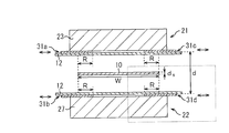
- FIG. 2A to 2C are diagrams showing an example of the configuration of the induction heating apparatus.
- FIG. 2A is a view of an example of the induction heating device 20 of the present embodiment as viewed from the side of the line, and is cut along the longitudinal direction of the strip steel plate 10 (in the vertical direction in FIG. 1). It is a longitudinal cross-sectional view.
- the strip steel plate 10 is conveyed in the left direction (see the arrow from the right to the left in FIG. 2A).
- FIG. 2B is a longitudinal sectional view of an example of the induction heating device 20 of the present embodiment as viewed from the direction AA ′ in FIG.
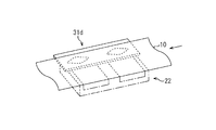
- FIG. 2B is a partial perspective view showing a part of an example of the induction heating device 20 of the present embodiment.
- the lower right region shown in FIG. 2B is viewed from above the strip steel plate 10.
- the induction heating device 20 includes an upper inductor 21 and a lower inductor 22.
- the upper inductor 21 includes a core 23, an upper heating coil (heating coil) 24, and shielding plates 31a and 31c.
- the upper heating coil 24 is a conductor wound around the core 23 through a slot of the core 23 (here, a recessed portion of the core 23), and is a coil having a number of turns “1” (so-called single turn).
- the upper side heating coil 24 has the part whose shape of the longitudinal cross-section is a hollow rectangle.
- a water cooling pipe is connected to an end face of the hollow rectangular hollow portion.
- the cooling water supplied from the water cooling pipe flows into a hollow rectangular hollow portion (inside the upper heating coil 24), and the upper inductor 21 is cooled. Further, shielding plates 31 a and 31 c are attached to the bottom surface (slot side) of the core 23.
- the length l 1 of the upper inductor 21 is 45 [mm]
- the length l 2 is 180 [mm]
- the length l 3 is 80 [mm]
- the length l 4 is 180 [mm].
- the length l 5 is 45 [mm]
- the length l 6 is 45 [mm]
- the length l 7 is 45 [mm].
- the width W of the strip steel plate 10 is 900 [mm]
- the thickness d s is 0.3 [mm]. However, these dimensions are not limited to the above values.
- the lower inductor 22 includes a core 27, a lower heating coil (heating coil) 28, and shielding plates 31b and 31d.
- the lower heating coil 28 is a conductor wound around the core 27 through the slot of the core 27, and is a coil having a number of turns “1” (so-called single turn).
- the lower heating coil 28 has a portion whose longitudinal section is a hollow rectangle. A water-cooled pipe is connected to the end surface of the hollow rectangular hollow portion, and cooling water can flow through the hollow rectangular hollow portion.
- the coil surface of the upper heating coil 24 of the upper inductor 21 (the surface on which the loop is formed, the surface through which the lines of magnetic force penetrate) and the coil surface of the lower heating coil 28 of the lower inductor 22 are the strip steel plate 10. Is facing through. Further, the plate surfaces of the shielding plates 31 a to 31 d (31) are opposed to the side end portions (edges) in the plate width direction of the strip steel plate 10. In order to satisfy such a positional relationship, the upper inductor 21 is provided above the strip steel plate 10 (near the upper surface of the horizontal portion of the second container 12), and the lower inductor 22 is provided on the strip steel plate 10. It is provided on the lower side (near the lower surface of the horizontal portion of the second container 12).
- the upper inductor 21 and the lower inductor 22 have the same configuration, although the positions to be arranged are different. Further, in the present embodiment, the shielding plates 31a to 31d can be individually moved in the width direction of the strip steel plate 10 (the direction of the double arrow shown in FIG. 2B) based on the operation of a driving device (not shown). .
- the distance d between the upper heating coil 24 and the lower heating coil 28, the heating coil width l 2, l 4 of the upper heating coil 24, the heating coil width l 2 of the lower heating coil 28, l 4 is the same.
- a position where the “overlapping length R in the width direction of the belt-shaped steel plate 10” between both side end portions of the belt-shaped steel plate 10 and the shielding plates 31a to 31d is defined as a reference position.
- the heating coil width is the length in the width direction of the upper heating coil 24 (lower heating coil 28) in the slot. In the example shown in FIG. 2A, the heating coil width is equal to the length in the width direction of each of the copper pipes 41a to 41d shown in FIG.
- the heating coil width of the upper heating coil 24 and the heating coil width of the lower heating coil 28 are simply referred to as the heating coil width as necessary, and the upper heating coil 24 and the lower heating coil 28 are The interval is referred to as a gap as necessary.
- FIG. 3 is a diagram illustrating an example of the configuration of the upper heating coil 24 and the lower heating coil 28.
- the arrow shown in FIG. 3 has shown an example of the direction through which the electric current flows in a certain time.
- the upper heating coil 24 includes copper pipes 41a and 41b, and copper bus bars (connection boards) 42b connected to the base ends of the copper pipes 41a and 41b.
- the lower heating coil 28 includes copper pipes 41c and 41d and a copper bus bar 42f connected to the base end side of the copper pipes 41c and 41d.
- One end of the upper heating coil 24 (the tip side of the copper pipe 41a) is connected to one output end of the AC power supply device 18 via the copper bus bar 42a.
- the other end of the upper heating coil 24 (the tip side of the copper pipe 41b) is connected to one end of the lower heating coil 28 (the tip side of the copper pipe 41c) via copper bus bars 42c to 42e.
- the other end of the lower heating coil 28 (the tip side of the copper pipe 41d) is connected to the other output end of the AC power supply device 18 through copper bus bars 42i, 42h, and 42g.
- the upper heating coil 24 and the lower heating coil 28 are connected in series to the AC power supply device 18 by combining the copper pipes 41a to 41d (41) and the copper bus bars 42a to 42i (42).
- the coils are connected and each has a number of turns of “1”.
- a large magnetic flux is generated from the top to the bottom surrounded by the copper pipe 41 and the copper bus bar 42, and this magnetic flux penetrates the belt-shaped steel plate 10, thereby forming a joule in the belt-shaped steel plate 10. Heat is generated and the strip steel plate 10 is heated.
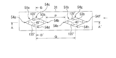
- FIG. 4A to 4D are diagrams showing an example of the configuration of the shielding plate 31.
- FIG. 4A is a top view of the shielding plate 31 as viewed from directly above (the strip-shaped steel plate 10 side).
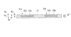
- FIG. 4B is a longitudinal sectional view as seen from the direction AA ′ in FIG. 4A.
- FIG. 4C is a longitudinal sectional view as seen from the BB ′ direction of FIG. 4A.
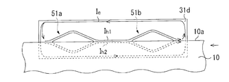
- FIG. 4D is a view of the region including the shielding plate 31d shown in FIG. 4E is a cross-sectional view seen from the CC ′ direction of FIG. 4B.
- FIG. 4A is a top view of the shielding plate 31 as viewed from directly above (the strip-shaped steel plate 10 side).
- FIG. 4B is a longitudinal sectional view as seen from the direction AA ′ in FIG. 4A.
- FIG. 4C is a longitudinal sectional view as seen from the BB ′ direction of FIG. 4A.
- FIG. 4D conceptually shows eddy currents I e , I h1 , I h2 flowing through the shielding plate 31d.
- belt-shaped steel plate 10 is conveyed in the direction of the arrow shown to the right end of FIG. 4A and 4D.
- the conveyance direction of the strip steel plate 10 substantially coincides with the depth direction of the shielding plate 31, and the direction (width direction of the strip steel plate 10) perpendicular to the conveyance direction of the strip steel plate 10 on the plate surface is substantially the width direction of the shielding plate.
- the thickness (thickness) direction of the shielding plate 31 substantially coincides with the direction perpendicular to the coil surface of the heating coil (for example, the upper heating coil 24) (the thickness direction of the strip steel plate 10).
- the shielding plate 31 is made of copper and has recesses 51a and 51b (51) each having the same size and shape. These concave portions 51 a and 51 b are arranged with an interval in the conveying direction of the strip steel plate 10.
- the shape (opening shape) in the plate surface direction (the plate thickness direction of the shielding plate 31) of the recesses 51a and 51b is a rhombus in which the corners 54a to 54h (54) are rounded. .
- the edge part of the recessed part 51a Comprising: The upstream corner part in the conveyance direction of the strip-shaped steel plate 10, and the edge part of the recessed part 51b, Comprising: The downstream corner part in the conveyance direction of the strip-shaped steel sheet 10
- the distance P is 150 [mm].
- the distance Q is 310 [mm].
- the shielding plate 31 is arranged in the width direction of the strip steel plate 10 so that the side end 10a of the strip steel plate 10 and the recesses 51a and 51b overlap each other when viewed from the vertical direction. Is moving.
- the side end 10a of the strip steel plate 10 and the longest portion on the plate surface of the recesses 51a and 51b are in the vertical direction ( When viewed from the direction perpendicular to the plate surface of the strip-shaped steel plate 10, they overlap each other.
- the induction heating device 20 is operated, and the main magnetic flux generated by passing an alternating current through the upper heating coil 24 and the lower heating coil 28 is shielded. It can be shielded by the plate 31.
- an eddy current is generated at both ends of the strip steel plate 10 by the main magnetic flux, the eddy current hits the side end of the strip steel plate, the current density at the side end increases, and the temperature between the side end and the vicinity thereof is increased. There is a difference.
- the present inventors have found that the above-described recesses 51a and 51b are non-conductive soft magnetic plates made of soft magnetic ferrite (for example, Mn—Zn based ferrite, Ni—Zn based ferrite) or the like. It was found that this temperature difference can be reduced by accommodating 52a and 52b (52).
- the non-conductive soft magnetic plates 52a and 52b can be fixed to the recesses 51a and 51b of the shielding plate 31 using, for example, an adhesive. That is, as shown in FIG.
- a part of the eddy current Ie flowing so as to go around the end of the shielding plate 31 is branched, and the eddy currents I h1 and I h2 are formed along the edges of the recesses 51a and 51b. If it is made to flow, the eddy current of the strip steel plate 10 generated by the magnetic field generated by the eddy currents I h1 and I h2 cancels the eddy current (eddy current due to the main magnetic flux) flowing to the side end of the strip steel plate 10. Weaken.
- the non-conductive soft magnetic plates (non-conductive soft magnetic materials) 52a and 52b are accommodated in the recesses 51a and 51b formed in the shielding plate 31. If a conductive material is used in place of the non-conductive soft magnetic plates 52a and 52b, the shielding plate itself is conductive.
- the conductive material and the shielding plate are used as an integral conductive member.
- the eddy current distribution cannot be strongly limited to the edges of the recesses 51a and 51b.
- the nonconductive soft magnetic plates 52a and 52b are protected on the nonconductive soft magnetic plates 52a and 52b (on the strip-shaped steel plate 10 side) from heat from the outside.
- the plates 53a and 53b (53) are fixed and stored, for example, with an adhesive.
- the thickness D of the shielding plate 31 is 25 [mm]
- the depths D m of the recesses 51a and 51b are 15 [mm].
- the non-conductive soft magnetic plates 52a and 52b have a shape that matches the shape of the bottom surface of the recesses 51a and 51b in the plate surface direction (the shape of the cross section perpendicular to the thickness direction of the shielding plate 31), and the thickness DF is 5 [mm].
- these dimensions are not limited to the above values.
- the present inventors have the thickness DF of 1 [mm] or more (and the depth of the recesses 51a and 51b).
- the heat-resistant plates 53a and 53b have a shape that matches the shape in the plate surface direction of the bottom of the recesses 51a and 51b of the shielding plate 31 (the shape of the cross section perpendicular to the thickness direction of the shielding plate 31). D is 10 [mm].
- the magnitudes of the eddy currents I h1 and I h2 flowing along the edges of the recesses 51a and 51b become larger. Therefore, the magnetic field generated by these increased eddy currents also increases, and a larger eddy current that cancels the eddy current flowing in the side end of the strip steel plate 10 can be generated in the vicinity of the side end. As a result, an effect of sufficiently pushing the eddy current at the side end portion of the strip steel plate 10 generated by the main magnetic flux into the inner side in the width direction of the strip steel plate 10 is produced.
- the corners 54a to 54h of the recesses 51a and 51b are rounded.
- at least the corners 54a and 54e, which are the “downstream corners in the conveying direction of the strip steel plate 10” of the recesses 51a and 51b are rounded so as to protrude in the downstream direction
- the recesses 51a and 51b The corners 54b and 54f, which are “upstream corners in the conveying direction of the belt-shaped steel plate 10,” may be rounded so as to protrude in the upstream direction.
- the non-conductive soft magnetic plates 52a, 52b, recesses 51a since the eddy currents I h1, I h2 flowing along the edge of 51b is increased, even if the steel strip 10 is meandering, vortex It is possible to maintain to some extent the magnitudes of the currents I h1 and I h2 and the effect of pushing the eddy current flowing in the side end of the strip steel plate 10 inward from the side end. Therefore, even if the strip steel plate 10 meanders, the change in temperature distribution in the width direction of the strip steel plate 10 can be relaxed.
- FIG. 5 is a diagram illustrating an example of the relationship between the shielding plate insertion amount (shield plate insertion amount) and the width-temperature deviation ratio.
- the shielding plate insertion amount corresponds to “the overlapping length R in the width direction of the strip-shaped steel plate 10 between the both end portions of the strip-shaped steel plate 10 and the shield plate (see FIG. 2B).
- a flat shield plate having no recess is used.
- a shielding plate having a recess in which a nonconductive soft magnetic plate is accommodated is used as in this embodiment.
- FIG. 5 is based on the results of experiments conducted under the following conditions.
- Heating coil width 1300 [mm]
- Core material Ferrite Heating material: Stainless steel plate (width 900 [mm], thickness 0.3 [mm])
- Inter-coil gap 180 [mm]
- Feeding speed 50 [mpm (m / min)]
- Heating temperature 400 to 730 [° C.] (Set the central heating amount to 330 [° C.])
- Power supply frequency 8.5 [kHz]
- Energizing current 3650 [AT]
- Material of shielding plate Copper External dimensions of shielding plate: width 230 [mm], depth 600 [mm], thickness 25 [mm]
- Non-conductive soft magnetic plate material Ni-Zn ferrite
- Non-conductive soft magnetic plate thickness 5 [mm]
- Standard of insertion amount of shielding plate 90 [mm]
- FIG. 5 shows that the smaller the width temperature deviation ratio is (the closer the width temperature deviation ratio is to 1), the more smooth the temperature distribution in the width direction of the strip steel plate 10 can be realized. Moreover, it shows that even if the strip steel plate 10 meanders, the change in the temperature distribution in the width direction of the strip steel plate 10 can be reduced as the inclination of the graph is small.
- the temperature distribution in the width direction of the strip steel plate 10 is smoothed, and the strip steel plate 10 meanders. It can be seen that both the relaxation of the change in temperature distribution in the width direction of the strip-shaped steel sheet 10 can be realized.
- the shielding plate 31 is disposed between the side end portion of the belt-shaped steel plate 10 and the cores 23 and 27 (the upper heating coil 24 and the lower heating coil 28).
- the shielding plate 31 is formed with two recesses 51a and 51b so as to have an interval in the conveying direction of the strip steel plate 10. Further, non-conductive soft magnetic plates 52a and 52b are accommodated in the recesses 51a and 51b. Therefore, the magnetic field generated by the eddy current flowing in the shielding plate 31d by the main magnetic flux can be strengthened, and the magnitudes of the eddy currents I h1 and I h2 flowing along the edges of the recesses 104a and 104b can be further increased.
- the strip steel plate 10 meanders by flowing large eddy currents I h1 and I h2 along the edges of the recesses 51a and 51b, the eddy currents I h1 and I h2 are The effect of pushing the eddy current flowing in the end portion inward from the side end portion can be maintained to some extent. Therefore, even if the strip steel plate 10 meanders, the change in temperature distribution in the width direction of the strip steel plate 10 can be alleviated.
- the magnetic field generated by the eddy current flowing through the shielding plate 31d pushes the side end of the strip steel plate 10 back to the center side in the width direction of the strip steel plate 10 to meander the strip steel plate 10. Can be suppressed.
- the corners 54a and 54e which are the “downstream corners in the conveying direction of the strip steel plate 10” of the recesses 51a and 51b, are rounded so as to protrude in the downstream direction, and the recess 51a.
- 51b, the corners 54b and 54f which are “upstream corners in the conveying direction of the strip steel plate 10,” are rounded so as to protrude in the upstream direction. Therefore, even when the strip steel plate 10 meanders, the amount of change in “the overlapping length in the transport direction of the strip steel plate 10 between the side end 10a of the strip steel plate and the recesses 51a and 51b” when viewed from above is reduced.
- the amount of change in the indentation effect of the eddy current flowing in the side end of the strip steel plate 10 can also be reduced. Therefore, the change of the temperature distribution in the width direction of the strip steel plate 10 when the strip steel plate 10 meanders can be further alleviated.
- the heat-resistant plates 53a and 53b are housed on the non-conductive soft magnetic plates 52a and 52b (on the strip-like steel plate 10 side), even if the induction heating device is used at a high temperature, It is possible to prevent the characteristics of the conductive soft magnetic plates 52a and 52b from deteriorating. However, when the induction heating device is not used at a high temperature, it is not always necessary to use the heat-resistant plates 53a and 53b.
- the thickness of the non-conductive soft magnetic plate stored in the recess of the shielding plate may be the same as the depth of the recess. Thus, the thickness of the non-conductive soft magnetic plate may be the same as the depth of the recess or less than the depth of the recess.
- FIGS. 6A and 6B show first and second modifications of the shielding plate, respectively, and are views of the shielding plate viewed from directly above (the strip steel plate 10 side). These correspond to FIG. 4A.
- the shielding plate 61 is made of copper, and is disposed with an interval in the conveying direction of the belt-shaped steel plate 10, and has recesses 62a and 62b (62) each having the same size and shape. In these respects, the shielding plate 61 is the same as the shielding plate 31 shown in FIGS. 4A to 4C. However, as shown to FIG.
- board surface direction of the recessed part 62a is upstream from the downstream in the conveyance direction (direction of the arrow shown by FIG. 6A and 6B) of the strip
- Each of the corners 64a to 64c (64) is a rounded triangle. In such a case, it is preferable that at least the corner 64a which is the “upstream corner in the conveying direction of the strip steel plate 10” of the recess 62a is rounded so as to protrude in the upstream direction.
- the shape (opening shape) of the recess 62b in the plate surface direction is tapered from the upstream side to the downstream side in the conveying direction of the strip steel plate 10, and the corners 64d to 64f (64) are rounded. It is a triangular shape. In such a case, it is preferable that at least the corner 64d, which is the “downstream corner in the conveying direction of the strip steel plate 10” of the recess 62b, is rounded so as to protrude in the downstream direction.
- a non-conductive soft magnetic plate having a shape that matches the shape of the bottom surface of the recesses 62a and 62b (the shape of the cross section perpendicular to the thickness direction of the shielding plate 61), and the heat-resistant plates 63a and 63b (63). are fixed and stored in the recesses 62a and 62b using an adhesive or the like.
- the shielding plate 71 is made of copper. As shown in FIG. 6B, the number of recesses 72 formed in the shielding plate 71 is one. As shown in FIG. 6B, the shape of the recess 72 in the plate surface direction is such that “the upstream corner (corner portion 54b) in the transport direction of the strip steel plate 10” of the recess 51a shown in FIGS. 4A to 4C and the recess 51b.
- the “corner portions 54e on the downstream side in the conveying direction of the belt-shaped steel plate 10” are connected to each other, and the respective corner portions 74a to 74f (74) are rounded.
- the concave portion formed in the shielding plate includes a portion (second portion) tapering from the downstream side to the upstream side in the transport direction of the strip steel plate 10 and the upstream side in the transport direction of the strip steel plate 10. It is preferable to include a portion (first portion) that tapers toward the downstream side. These first part and second part may be formed individually (FIGS. 4A and 6A) or integrally (FIG. 6B). Furthermore, it is preferable that the tapered first portion and the second portion face each other in the conveying direction of the strip steel plate 10.
- the edge of the concave portion of the shielding plate can be formed in accordance with the path of the eddy current flowing through the strip steel plate 10.
- board surface direction of the recessed part formed in a shielding board may be what shape, and the number may be 1 or 2 or more.
- the recess has a portion (third portion) that tapers from the side far from the center in the width direction of the conductor plate (direction perpendicular to the transport direction) toward the side closer to the center in the width direction of the conductor plate.
- the amount of change in the effect of the magnetic field generated by the eddy current flowing in the shielding plate pushing the side end of the strip steel plate toward the center in the width direction of the strip steel plate can be gradually increased, and the meandering of the conductor plate can be suppressed. Can be controlled more flexibly.
- two third portions are included in the two recesses 51 a and 51 b of the shielding plate 31.
- the third portion may be included in this one recess.
- the above-described pushing effect can be more uniformly generated.
- a portion (fourth portion) that tapers from the side closer to the center in the width direction of the conductor plate toward the side farther from the center in the width direction of the conductor plate may be included.
- FIG. 6C shows a third modification of the shielding plate, and is a cross-sectional view of the shielding plate when cut in the thickness direction of the shielding plate along the conveying direction of the strip steel plate 10.
- FIG. 6C corresponds to FIG. 4B.
- the shielding plate 81 is made of copper, and is disposed with a gap in the conveying direction of the strip steel plate 10, and has recesses 82a and 82b (82) having the same size and shape.
- board surface direction of the recessed part 82a, 82b is a rhombus which each corner
- the shielding plate 81 shown in FIG. 6C is formed by overlapping the upper plate 84a and the lower plate 84b and fixing them.
- the shielding plate may be formed integrally or may be formed by combining a plurality of members.
- the shielding plate is made of copper, but the shielding plate is not limited to a copper plate. That is, as long as the shielding plate is a conductor, preferably a conductor having a relative magnetic permeability of 1, the shielding plate may be formed of any material.
- the shielding plate can be formed of aluminum.
- a strip steel plate (conductor plate) is generated by the main magnetic flux by increasing the magnitude of eddy current in the shielding plate generated in the vicinity of the nonconductive soft magnetic plate (nonconductive soft magnetic material). ) The magnitude of the eddy current flowing in the side end portion of 10 is reduced. Furthermore, since the conductive shielding plate is interposed between the core (or the heating coil) and the non-conductive soft magnetic plate, it is possible to avoid the main magnetic flux passing directly through the non-conductive soft magnetic plate. .
- the induction heating device includes: a heating coil; a core; a conductive shielding plate disposed between the core and a side end portion in a direction perpendicular to the conveying direction of the strip steel plate; What is necessary is just to provide the nonelectroconductive soft-magnetic board attached to a shielding board so that a shielding board may interpose with a soft-magnetic board.
- FIGS. 7A to 7C and FIGS. 8A to 8C are longitudinal sectional views showing an example of the configuration of the shielding plate in the fourth to sixth modifications of the present embodiment.
- 8A to 8C are perspective views showing an example of the configuration of the shielding plate in the seventh to ninth modifications of the present embodiment.
- non-conductive soft magnetic plates 102a and 102b (102) are arranged on a flat shielding plate 101, and the non-conductive soft magnetic plate 102 is made of a strip-shaped steel plate. It is made to oppose the side edge part.
- the non-conductive soft magnetic plate may be attached to the shielding plate so that the convex portion is formed on the shielding plate without forming the concave portion on the shielding plate.
- the eddy current in the shielding plate at the peripheral edge of the contact surface between the shielding plate and the non-conductive soft magnetic plate can be increased.
- a recess in the shielding plate and disposing a non-conductive soft magnetic plate in the recess eddy current is constrained at the edge of the recess, and the distance between the edge of the recess and the non-conductive soft magnetic plate is reduced. Since it can be shrunk, a large eddy current can be secured at the edge of the recess. Therefore, as shown in FIG.
- the concave portions 114a and 114b (114) are formed in the shielding plate 111, and the concave portions 114 of the shielding plate 111 are formed so that the convex portions are formed on the shielding plate 111.
- the non-conductive soft magnetic plates 112a and 112b (112) may be attached to each other.
- the recesses 124a and 124b (124) of the shielding plate 121 are non-conductive soft magnetic plates 122a and 122b (122) having different shapes on the upper surface and the lower surface. May be attached.
- a non-conductive soft magnetic plate 202 is attached on a shielding plate 201 having convex portions (two rhombus portions) 205a, 205b (205).
- the eddy current flowing through the edge of the convex portion 205 can be increased.
- the shape (outer periphery shape) of a shielding board is not specifically limited.
- the shielding plate 211 has recesses (two rhombus portions) 214a and 214b (214), and the shielding plate 211 follows the outer peripheral shape (opening shape) of the recess 214. It has frame parts 216a and 216b.
- the non-conductive soft magnetic plates 212a and 212b (212) are accommodated in the recess 214. In this case, the eddy current flowing at the edge of the recess 214 can be increased.
- convex portions (two rhombus portions) 225a and 225b (225) are formed on the shielding plate 221, and the shielding plate 221 has an outer peripheral shape (base end) of the convex portion 225. The outer peripheral shape is similar (along) to (the shape).
- a non-conductive soft magnetic plate 222 is disposed on the shielding plate 221 so as to surround the edge of the convex portion 225. In this case, the eddy current flowing at the edge of the convex portion 225 can be increased.
- a heat-resistant plate may be attached on the non-conductive soft magnetic plate of each modification shown in FIGS. 7A to 7C and FIGS. 8A to 8C.
- the shape and number of the recessed part or convex part of the shielding board in a board surface direction are not specifically limited.
- the shape and number of non-conductive soft magnetic plates are not particularly limited.
- 4E is a cross-sectional view as seen from the direction CC ′ of FIG. 4B.
- the cut surface includes non-conductive soft magnetic plates 52a and 52b (52), and a boundary portion (boundary between the shielding plate 31 and the non-conductive soft magnetic plate 52). Line) draws a closed curve (two closed curves). That is, the cut surface includes a case where the shielding plate surrounds the non-conductive soft magnetic plate and a case where the non-conductive soft magnetic plate surrounds the shielding plate.
- the shielding plate has a cut surface (cut surface parallel to the coil surface) perpendicular to the thickness direction including the nonconductive soft magnetic material, the nonconductive soft magnetic material and the nonconductive
- the distance from the eddy current in the shielding plate strengthened by the conductive soft magnetic plate can be shortened.
- the above-mentioned boundary portion draws a closed curve (in a ring shape)
- the eddy current region to be strengthened can be increased, and the characteristics of the nonconductive soft magnetic plate can be fully utilized.
- the shielding plate and the nonconductive soft magnetic material are in contact with each other.
- a gap (a gap as a boundary) may exist between the shielding plate and the non-conductive soft magnetic material so that the non-conductive soft magnetic material can be easily attached to the shielding plate.
- the induction heating device when used at a high temperature or when the strip steel plate is rapidly heated, the temperature of the shielding plate may increase due to eddy current.
- a cooler such as a water-cooled pipe.
- This cooling method is not particularly limited.
- a water cooling line may be integrally formed in the shielding plate to cool the shielding plate, or air may be blown to the shielding plate by a blower to cool the shielding plate.
- Non-conductive soft magnetic plate heat-resistant plate
- the material constituting the nonconductive soft magnetic plate is not limited to soft magnetic ferrite as long as it is a nonconductive soft magnetic material.
- the non-conductive soft magnetic material may be a material obtained by pressing and solidifying powder or particles, or a material combining a plurality of blocks, instead of a plate.
- the shape of the non-conductive soft magnetic plate is not particularly limited. If a non-conductive soft magnetic plate can be arranged in accordance with the part where the eddy current flows inside the shielding plate (for example, the edge of the recess), a magnetic field that enhances the eddy current can be obtained.
- the conductive soft magnetic plate may have a hollow portion.
- the nonconductive soft magnetic plate is preferably solid.
- the heat-resistant plate is not necessarily a plate, and any material may be used as long as a heat-resistant material is used.
- the method of fixing the non-conductive soft magnetic plate and the heat-resistant plate stored in the recess in the recess is not limited to the method using an adhesive. For example, after securing insulation between the shielding plate, the non-conductive soft magnetic plate, and the heat-resistant plate, these can be fixed to the recess using a screw.
- positioning location of the induction heating apparatus 20 is not limited to the position shown in FIG. That is, the induction heating device 20 may be arranged in any way as long as the conductor plate can be induction heated by the transverse method.
- the induction heating device 20 may be disposed in the second container 12.
- the heating coil width and the gap between the heating coils are the same has been described as an example, but the heating coil width and the size of the gap are not particularly limited.
- the heating coil width is preferably equal to or greater than the gap (or the heating coil width is larger than the gap).
- the main magnetic field generated from the induction heating device 20 is larger than the leakage magnetic field, and the heating efficiency of the induction heating device 20 can be improved.
- the upper limit value of the heating coil width can be appropriately determined depending on the space in which the induction heating device 20 is disposed and the conditions such as the weight and cost required for the induction heating device 20.
- the number of heating coils and cores is not particularly limited. For example, a plurality of heating coils and cores can be arranged in the transport direction of the strip steel plate in order to perform flexible heating control of the strip steel plate. Further, the number of shielding plates is not particularly limited.
- a berth type induction heating apparatus is provided.
Landscapes
- Engineering & Computer Science (AREA)
- Chemical & Material Sciences (AREA)
- Physics & Mathematics (AREA)
- Mechanical Engineering (AREA)
- Materials Engineering (AREA)
- Crystallography & Structural Chemistry (AREA)
- Thermal Sciences (AREA)
- Metallurgy (AREA)
- Organic Chemistry (AREA)
- Electromagnetism (AREA)
- General Engineering & Computer Science (AREA)
- Power Engineering (AREA)
- General Induction Heating (AREA)
Abstract
Description
本願は、2010年2月19日に、日本に出願された特願2010-035198号に基づき優先権を主張し、その内容をここに援用する。
この問題点に関する技術として、特許文献1、2に記載の技術がある。
特許文献1に記載の技術では、コイルと、加熱対象の導体板の両側端との間のそれぞれに、非磁性金属材料からなる板状の可動遮蔽板を設けている。
また、特許文献2に記載の技術では、加熱対象の導体板の搬送方向に沿って、加熱パターンの異なる菱形コイルと長円形コイルとを配置して、導体板の幅方向について所望の加熱パターンで導体板を加熱している。
また、特許文献2に記載の技術では、特定の導体板に対しては、幅方向の温度分布の平滑度が低下することを抑制することができる。しかしながら、導体板の板幅が変更されると、板幅に応じてコイル自体を再設定しなければならない。したがって、コイル自体を動かすための機構が必要となり、板幅の変更に対して容易に且つ迅速に対応することが困難である。
さらに、特許文献1、2に記載の技術では、導体板が蛇行すると、導体板の幅方向の温度分布の平滑度が低下してしまう。
(2)上記(1)に記載のトランスバース式の誘導加熱装置は、前記非導電性軟磁性材に取り付けられる耐熱板を更に備え;前記耐熱板が前記非導電性軟磁性体よりも前記導体板の近くに配置されている。
(3)上記(1)に記載のトランスバース式の誘導加熱装置では、前記遮蔽板が、前記非導電性軟磁性材を含む前記コイル面に平行な切断面を有している。
(4)上記(1)に記載のトランスバース式の誘導加熱装置では、前記遮蔽板の前記導体板と対向する面に、前記導体板の搬送方向に垂直な方向における前記側端部と対向する凹部が形成されており;この凹部に、前記非導電性軟磁性材が収められている。
(5)上記(4)に記載のトランスバース式の誘導加熱装置では、前記凹部に、前記導体板の搬送方向に垂直な方向における中心部から遠い側から前記導体板の搬送方向に垂直な方向における中心部から近い側に向けて先細りになる部分が含まれている。
(6)上記(4)に記載のトランスバース式の誘導加熱装置では、前記凹部には、前記導体板の搬送方向における上流側から下流側に向けて先細りになる第一の部分と、前記導体板の搬送方向における下流側から上流側に向けて先細りになる第二の部分とが含まれ;これら第一の部分及び第二の部分が、前記導体板の搬送方向で相互に対向している。
(7)上記(4)に記載のトランスバース式の誘導加熱装置では、前記第一の部分が、前記下流側に向けて丸みを帯びており;前記第二の部分が、前記上流側に向けて丸みを帯びている。
[連続焼鈍ラインの構成]
図1は、鋼板の連続焼鈍ラインの概略構成の一例を示す側面図である。尚、各図では、説明の便宜上、必要な構成のみを簡略化して示している。
図1において、連続焼鈍ライン1は、第1の容器11と、第2の容器12と、第3の容器13と、第1のシールローラ組立体14と、移送器15と、第2のシールローラ組立体16と、気体供給装置17と、交流電源装置18と、ローラ19a~19u(19)と、誘導加熱装置20とを備えている。
第2のシールローラ組立体16は、このようにして急冷された帯状鋼板10を、第3の容器13と外気とを遮断しながら後工程に送り出す。
以上のような「帯状鋼板10の搬送経路」となる「第1の容器11、第2の容器12、第3の容器13、及び移送器15」には、気体供給装置17によって非酸化性の気体が供給されている。そして、外部(外気)と内部(連続焼鈍ライン1の内部)とを遮断する「第1のシールローラ組立体14及び第2のシールローラ組立体16」によって、第1の容器11、第2の容器12、第3の容器13、及び移送器15は、非酸化性の気体雰囲気が保たれた状態となる。
図2A~2Cは、誘導加熱装置の構成の一例を示す図である。
具体的に図2Aは、本実施形態の誘導加熱装置20の一例を、ラインの側方から見た図であって、帯状鋼板10の長手方向に沿って(図1の上下方向に)切った縦断面図である。図2Aでは、左方向に帯状鋼板10が搬送されている(図2Aの右から左に向かう矢印を参照)。また、図2Bは、本実施形態の誘導加熱装置20の一例を図1のA-A’方向から見た縦断面図(すなわち通板方向の下流から見た図)である。図2Bでは、図の奥から手前の方向に帯状鋼板10が搬送されている。また、図2Cは、本実施形態の誘導加熱装置20の一例の一部を示す部分斜視図である。図2Cでは、図2Bに示した右下の領域を、帯状鋼板10の上方から俯瞰している。
上側誘導器21は、コア23と、上側加熱コイル(加熱コイル)24と、遮蔽板31a、31cとを備えている。
上側加熱コイル24は、コア23のスロット(ここではコア23の凹み部)を通してコア23に巻き回された導体であり、巻数が「1」のコイル(いわゆるシングルターン)である。また、図2Aに示すように、上側加熱コイル24は、その縦断面の形状が中空の長方形である部分を有する。この中空の長方形の中空部分の端面には、水冷パイプが接続されている。この水冷パイプから供給される冷却水が中空の長方形の中空部分(上側加熱コイル24の内部)に流れ、上側誘導器21が冷却される。また、コア23の底面(スロット側)には、遮蔽板31a、31cが取り付けられている。
尚、図2Aにおいて、上側誘導器21の長さl1は45[mm]、長さl2は180[mm]、長さl3は80[mm]、長さl4は180[mm]、長さl5は45[mm]、長さl6は45[mm]、長さl7は45[mm]である。また、帯状鋼板10の幅Wは900[mm]、厚みdsは、0.3[mm]である。ただし、これらの寸法は、上記各値に限定されるわけではない。
下側加熱コイル28も、上側加熱コイル24と同様に、コア27のスロットを通してコア27に巻き回された導体であり、巻数が「1」のコイル(いわゆるシングルターン)である。更に、下側加熱コイル28は、上側加熱コイル24と同様に、その縦断面の形状が中空の長方形である部分を有している。この中空の長方形の中空部分の端面には、水冷パイプが接続され、中空の長方形の中空部分に冷却水を流すことができる。
以上のように、上側誘導器21と、下側誘導器22とは、配置する位置が異なるが、同じ構成を有する。
また、本実施形態では、不図示の駆動装置の動作に基づいて、遮蔽板31a~31dを、それぞれ帯状鋼板10の幅方向(図2Bに示す両矢印の方向)に個別に移動させることができる。
ここで、加熱コイル幅は、スロット内にある上側加熱コイル24(下側加熱コイル28)の幅方向における長さである。図2Aに示す例では、加熱コイル幅は、後述する図3に示す各銅パイプ41a~41dの幅方向の長さと等しく、コア23、27のスロットの幅と略同じ寸法である。
尚、以下の説明では、上側加熱コイル24の加熱コイル幅及び下側加熱コイル28の加熱コイル幅を、必要に応じて単に加熱コイル幅と称し、上側加熱コイル24と下側加熱コイル28との間隔を、必要に応じてギャップと称する。
図3は、上側加熱コイル24及び下側加熱コイル28の構成の一例を示す図である。尚、図3に示す矢印は、ある時刻での電流の流れる方向の一例を示している。
図3に示すように、上側加熱コイル24は、銅パイプ41a、41bと、銅パイプ41a、41bの基端側に接続されている銅ブスバー(結線板)42bとを有する。また、下側加熱コイル28は、銅パイプ41c、41dと、銅パイプ41c、41dの基端側に接続されている銅ブスバー42fとを備えている。
以上のように、上側加熱コイル24及び下側加熱コイル28は、銅パイプ41a~41d(41)と、銅ブスバー42a~42i(42)とを組み合わせることによって、交流電源装置18に対して直列に接続され、夫々巻数が「1」のコイルを形成している。この図3では、大きな磁束が銅パイプ41と銅ブスバー42とによって囲まれた中央部の上から下へ向かって生成され、この磁束が帯状鋼板10を貫通することにより、帯状鋼板10内にジュール熱が発生し、帯状鋼板10が加熱される。
図4A~4Dは、遮蔽板31の構成の一例を示す図である。
具体的に図4Aは、遮蔽板31をその真上(帯状鋼板10側)から見た上面図である。また、図4Bは、図4AのA-A’方向から見た縦断面図である。また、図4Cは、図4AのB-B’方向から見た縦断面図である。また、図4Dは、図2Cに示した遮蔽板31dを含む領域を帯状鋼板10の真上から見た図である。図4Eは、図4BのC-C’方向から見た横断面図である。尚、図4Dでは、帯状鋼板10と遮蔽板31dとの位置関係を説明するために必要な部分のみを示している。また、図4Dでは、遮蔽板31dに流れる渦電流Ie、Ih1、Ih2を概念的に示している。尚、図4A及び図4Dの右端に示している矢印の方向に帯状鋼板10が搬送されている。
なお、帯状鋼板10の搬送方向が遮蔽板31の奥行方向と略一致し、板面上における帯状鋼板10の搬送方向に垂直な方向(帯状鋼板10の幅方向)が遮蔽板の幅方向と略一致している。また、遮蔽板31の板厚(厚み)方向は、加熱コイル(例えば、上側加熱コイル24)のコイル面に垂直な方向(帯状鋼板10の板厚方向)と略一致している。
図4Aに示すように、凹部51a、51bの板面方向(遮蔽板31の板厚方向)における形状(開口形状)は、それぞれの角部54a~54h(54)が丸みを帯びた菱形である。
図4Aにおいて、凹部51aの端部であって、帯状鋼板10の搬送方向における上流側の隅部と、凹部51bの端部であって、帯状鋼板10の搬送方向における下流側の隅部との距離Pは、150[mm]である。また、凹部51aの端部であって、帯状鋼板10の搬送方向における中央に位置する隅部と、凹部51bの端部であって、帯状鋼板10の搬送方向における中央に位置する隅部との距離Qは、310[mm]である。
このような位置関係になるように遮蔽板31を配置することにより、誘導加熱装置20を動作させ、上側加熱コイル24及び下側加熱コイル28に交流電流を流すことによって発生する主磁束を、遮蔽板31で遮蔽することができる。しかしながら、主磁束によって帯状鋼板10の両側端部には渦電流が発生し、渦電流が帯状鋼板の側端に当たって、この側端における電流密度が高くなり、側端とその近傍との間に温度差が生じる。そこで、本発明者らは、鋭意研究の結果、前述した凹部51a、51bに、軟磁性フェライト(例えば、Mn-Zn系フェライト、Ni-Zn系フェライト)等で構成される非導電性軟磁性板52a、52b(52)を収めることにより、この温度差を緩和できることを見出した。ここで、この非導電性軟磁性板52a、52bは、遮蔽板31の凹部51a、51bに、例えば接着剤を用いて固定することができる。
すなわち、図4Dに示すように、遮蔽板31の端部を周回するように流れる渦電流Ieの一部を分岐させて、凹部51a、51bの縁に沿って渦電流Ih1、Ih2が流れるようにすれば、渦電流Ih1、Ih2が生成する磁界によって生じる帯状鋼板10の渦電流が、帯状鋼板10の側端部に流れている渦電流(主磁束による渦電流)を相殺して弱める。その結果、帯状鋼板10の側端部に流れている渦電流を、帯状鋼板10の幅方向における内側に押し込む効果を生み出すことができ、帯状鋼板10の側端10a近傍の渦電流密度の均質化が進み、帯状鋼板10の側端部(高温部)と、この側端部よりも内側の部分(低温部)との間の温度差が緩和される。
以上のような理由で、本実施形態では、遮蔽板31に形成した凹部51a、51bに非導電性軟磁性板(非導電性軟磁性材)52a、52bを収めている。もし、非導電性軟磁性板52a、52bの代わりに導電性の材料を用いた場合には、遮蔽板そのものが導電性であるため、この導電性の材料と遮蔽板とが一体の導電部材として作用し、渦電流の分布を凹部51a、51bの縁に強く限定することはできない。
さらに、本実施形態では、凹部51a、51bにおいて、非導電性軟磁性板52a、52bの上(帯状鋼板10側)に、非導電性軟磁性板52a、52bを外部からの熱から保護する耐熱板53a、53b(53)が、例えば接着剤により固定され、収められている。
以上のように、非導電性軟磁性板52a、52bを凹部51a、51bに収めることによって、主磁束により遮蔽板31に流れる渦電流によって生じる磁界が強化される。この磁界の強化により、凹部51a、51bの縁に沿って流れる渦電流Ih1、Ih2の大きさもより大きくなる。したがって、これらの大きくなった渦電流によって生じる磁界も大きくなり、帯状鋼板10の側端部に流れている渦電流を打ち消すより大きな渦電流を側端部近傍に生成させることができる。結果的には、主磁束により生成される帯状鋼板10の側端部の渦電流を、帯状鋼板10の幅方向における内側に十分に押し込む効果を生み出す。
図5は、遮蔽板挿入量(シールド板挿入量)と、幅温度偏差比との関係の一例を示す図である。
遮蔽板挿入量は、帯状鋼板10の両側端部と、遮蔽板との「帯状鋼板10における幅方向の重なり長さRに対応している(図2Bを参照)。また、幅温度偏差比は、帯状鋼板10における幅方向の温度分布における中央部の温度(板幅中央部温度)を端部の温度(板端部温度)で割った値(=板幅中央部温度/板端部温度)である。
図5において、グラフA1では、凹部を形成していない平板状の遮蔽板を用いている。グラフA2では、本実施形態のように非導電性軟磁性板が収められた凹部を備えた遮蔽板を用いている。
加熱コイル幅 :1300[mm]
コアの材質 :フェライト
加熱材料 :ステンレス鋼板(幅900[mm]、厚み0.3[mm])
コイル間ギャップ :180[mm]
通板速度 :50[mpm(m/分)]
加熱温度 :400~730[℃](中央昇温量を330[℃]に設定)
電源周波数 :8.5[kHz]
通電電流 :3650[AT]
遮蔽板の材質 :銅
遮蔽板の外形寸法 :幅230[mm]、奥行600[mm]、厚み25[mm]
遮蔽板の凹部の形状 :図4A(グラフA2)
非導電性軟磁性板の材質:Ni-Znフェライト
非導電性軟磁性板の厚み:5[mm]
遮蔽板挿入量の基準 :90[mm]
図5において、本実施形態のように、非導電性軟磁性板が収容された凹部を備えた遮蔽板を用いると、帯状鋼板10の幅方向における温度分布の平滑化と、帯状鋼板10が蛇行したときの帯状鋼板10の幅方向における温度分布の変化の緩和との双方を実現できることが分かる。
以上のように本実施形態では、帯状鋼板10の側端部と、コア23、27(上側加熱コイル24及び下側加熱コイル28)との間に遮蔽板31を配置する。この遮蔽板31には、帯状鋼板10の搬送方向において間隔を有するように2つの凹部51a、51bが形成されている。さらに、これらの凹部51a、51bには、非導電性軟磁性板52a、52bが収められている。したがって、主磁束により遮蔽板31dに流れる渦電流によって生じる磁界を強化し、凹部104a、104bの縁に沿って流れる渦電流Ih1、Ih2の大きさをより大きくすることができる。この結果、帯状鋼板10の幅方向における温度分布の平滑化を実現することができる。また、このように凹部51a、51bの縁に沿って大きな渦電流Ih1、Ih2を流すことにより、帯状鋼板10が蛇行しても、渦電流Ih1、Ih2が、帯状鋼板10の側端部に流れている渦電流をこの側端部より内側に押し込む効果をある程度保つことができる。よって、帯状鋼板10が蛇行しても、帯状鋼板10の幅方向における温度分布の変化を緩和することができる。さらに、帯状鋼板10が蛇行した場合であっても、遮蔽板31dに流れる渦電流によって生じる磁界が、帯状鋼板10の側端を帯状鋼板10の幅方向の中心側へ押し返し、帯状鋼板10の蛇行を抑制することができる。
<遮蔽板>
図6A~6Cは、遮蔽板の構成の変形例を示す図である。図6A、図6Bは、それぞれ、遮蔽板の第1、第2の変形例を示し、遮蔽板をその真上(帯状鋼板10側)から見た図である。これらは、図4Aに対応している。
図6Aにおいて、遮蔽板61は、銅製であり、帯状鋼板10の搬送方向に間隔を有して配置され、それぞれ大きさと形状が同一の凹部62a、62b(62)を有している。これらの点では、遮蔽板61は、図4A~4Cに示した遮蔽板31と同じである。ただし、図6Aに示すように、凹部62aの板面方向における形状(開口形状)は、帯状鋼板10の搬送方向(図6A及び図6Bに示されている矢印の方向)における下流側から上流側に向けて先細りになり、且つ、それぞれの角部64a~64c(64)が丸みを帯びた三角形である。このような場合には、少なくとも、凹部62aの「帯状鋼板10の搬送方向における上流側の隅部」である角部64aが、上流側方向に突き出るような丸みを帯びるようにするのが好ましい。
また、凹部62a、62bの底部の板面方向の形状(遮蔽板61の厚さ方向に垂直な断面の形状)に合う形状を有する非導電性軟磁性板と、耐熱板63a、63b(63)とが、凹部62a、62bに、接着剤等を用いて固定され、収められている。
なお、遮蔽板に形成する凹部の板面方向における形状(開口形状)は、どのような形状であってもよく、その数は、1であっても、2以上であってもよい。
図6Cにおいて、遮蔽板81は、銅製であり、帯状鋼板10の搬送方向に間隔を有して配置され、それぞれ大きさと形状が同一の凹部82a、82b(82)を有している。また、凹部82a、82bの板面方向における形状(開口形状)は、それぞれの角部が丸みを帯びた菱形である。このように、図6Cに示す遮蔽板81と、図4A~4Cに示した遮蔽板31とは、材質、形状、及び大きさが同じである。ただし、図6Cに示す遮蔽板81は、上板84aと下板84bとを重ね合わせてそれらを固定することにより形成される。
以上のように、遮蔽板は、一体で形成しても、複数の部材を組み合せて形成してもよい。
これらの他、本実施形態では、遮蔽板が銅製であるが、遮蔽板は銅製の板に限定されない。すなわち、遮蔽板が、導体、好ましくは比透磁率が1の導体であれば、どのような材料で遮蔽板を形成してもよい。例えば、アルミニウムで遮蔽板を形成することができる。
図7Aに示す本実施形態の第4の変形例では、平らな遮蔽板101の上に非導電性軟磁性板102a、102b(102)を配置し、非導電性軟磁性板102を帯状鋼板の側端部に対向させている。このように、遮蔽板に凹部を形成せず、遮蔽板上に凸部が形成されるように遮蔽板に非導電性軟磁性板を取り付けてもよい。この場合には、遮蔽板と非導電性軟磁性板との接触面の周縁部における遮蔽板中の渦電流を増加させることができる。しかしながら、遮蔽板に凹部を形成し、この凹部に非導電性軟磁性板を配置することによって、凹部の縁に渦電流を束縛し、この凹部の縁と非導電性軟磁性板との距離を縮めることができるため、凹部の縁により大きな渦電流を確保することができる。そのため、図7B(第5の実施形態)に示すように、遮蔽板111に凹部114a、114b(114)を形成し、遮蔽板111上に凸部が形成されるように遮蔽板111の凹部114に非導電性軟磁性板112a、112b(112)を取り付けてもよい。また、図7C(第6の実施形態)に示すように、遮蔽板121の凹部124a、124b(124)に上面の形状と下面の形状とが異なる非導電性軟磁性板122a、122b(122)を取り付けてもよい。
図4Eは、図4BのC-C’方向から見た断面図である。図4Eに示すように、この切断面には、非導電性軟磁性板52a、52b(52)が含まれており、遮蔽板31と非導電性軟磁性板52との間の境界部(境界線)が閉曲線(2つの閉曲線)を描いている。すなわち、この切断面には、遮蔽板が非導電性軟磁性板を取り囲む場合と、非導電性軟磁性板が遮蔽板を取り囲む場合とが含まれる。このように、遮蔽板が、非導電性軟磁性材を含む厚み方向に垂直な切断面(コイル面に平行な切断面)を有していると、非導電性軟磁性材と、この非導電性軟磁性板によって強められる遮蔽板中の渦電流との距離を短くすることができる。さらに、上述の境界部が閉曲線を描く(リング状である)ことにより、強化される渦電流の領域を増やすことができ、非導電性軟磁性板の特性を十分に活かすことができる。なお、非導電性軟磁性材の近傍を流れる遮蔽板中の渦電流の大きさをできる限り大きくするために、遮蔽板と非導電性軟磁性材とが接触していることが好ましい。しかしながら、非導電性軟磁性材を遮蔽板に容易に取り付けることができるように、遮蔽板と非導電性軟磁性材との間に隙間(境界部としての隙間)が存在してもよい。
非導電性軟磁性板を構成する材料は、非導電性の軟磁性体であれば、軟磁性フェライトに限定されない。また、非導電性軟磁性材は、板ではなく、粉体や粒体を押し固めた材料や、複数のブロックを組み合わせた材料であってもよい。また、非導電性軟磁性板の形状は、特に限定されない。遮蔽板の内側の渦電流が流れる部分(例えば、凹部の縁)に合わせて非導電性軟磁性板を配置することができれば、この渦電流を強化する磁界を得ることができるため、例えば、非導電性軟磁性板が、中空部を有してもよい。しかしながら、非導電性軟磁性板の磁性を十分に利用するためには、非導電性軟磁性板は、中実であることが好ましい。
耐熱板についても、必ずしも板である必要はなく、耐熱材を用いていればどのような材料であってもよい。
また、凹部に収められる非導電性軟磁性板及び耐熱板を、凹部内に固定する方法は、接着剤を用いる方法に限定されない。例えば、遮蔽板と非導電性軟磁性板及び耐熱板との絶縁を確保した上で螺子を用いてこれらを凹部に固定することができる。
本実施形態では、誘導加熱装置20の配置箇所は、図1に示した位置に限定されない。すなわち、導体板をトランスバース方式で誘導加熱することが可能であれば、誘導加熱装置20をどのように配置してもよい。例えば、第2の容器12内に誘導加熱装置20を配置してもよい。また、連続焼鈍ライン以外に誘導加熱装置20を適用してもよい。
また、本実施形態では、加熱コイル幅と加熱コイル間のギャップとが同じである場合を例に挙げて説明したが、加熱コイル幅及びこのギャップの大きさは、特に限定されるものではない。ただし、加熱コイル幅がギャップ以上である(又は加熱コイル幅がギャップよりも大きい)のが好ましい。この場合には、誘導加熱装置20から発生する主磁場が漏れ磁場よりも多くなり、誘導加熱装置20の加熱効率を良好にできる。尚、加熱コイル幅の上限値は、誘導加熱装置20を配置するスペースや、誘導加熱装置20に要求される重量やコスト等の条件によって適宜決定することができる。さらに、加熱コイル及びコアの配置数は、特に限定されない。例えば、加熱コイル及びコアは、帯状鋼板の加熱制御を柔軟に行なうために、帯状鋼板の搬送方向に複数配置することができる。
さらに、遮蔽板の配置数も、特に制限されない。例えば、加熱コイル及びコアの配置数に応じて、帯状鋼板の搬送方向に複数配置しても良い。1つの凹部を有する遮蔽板を複数配置して、複数の凹部を有する遮蔽板ユニットを形成しても良い。
また、本実施形態では、上側誘導器21と下側誘導器22とを設ける場合を例に挙げて示したが、上側誘導器21と下側誘導器22との何れか一方のみを設けてもよい。
18 交流電源装置
20 誘導加熱装置
21 上側誘導器
22 下側誘導器
23、27 コア
24 上側加熱コイル(加熱コイル)
28 下側加熱コイル(加熱コイル)
31、61、71、81、101、111、121、201、211、221 遮蔽板
51、62、72、82、114、124、214 凹部
205、225 凸部
52、102、112、122、202、212、222 非導電性軟磁性板(非導電性軟磁性材)
53、63、73 耐熱板(耐熱材)
Claims (7)
- 一方向に搬送される導体板の板面に交番磁界を交差させてこの導体板を誘導加熱するトランスバース方式の誘導加熱装置であって、
前記導体板の板面に対してコイル面が対向するように配置された加熱コイルと;
この加熱コイルが巻き回されたコアと;
このコアと、前記導体板の搬送方向に垂直な方向における側端部との間に配置され、導体から形成された遮蔽板と;
この遮蔽板に取り付けられる非導電性軟磁性材と;
を備え、
前記コアと、前記非導電性軟磁性材との間には、前記遮蔽板が介在している
ことを特徴とするトランスバース方式の誘導加熱装置。 - 前記非導電性軟磁性材に取り付けられる耐熱板を更に備え;
前記耐熱板が前記非導電性軟磁性体よりも前記導体板の近くに配置されている;
ことを特徴とする請求項1に記載のトランスバース方式の誘導加熱装置。 - 前記遮蔽板が、前記非導電性軟磁性材を含む前記コイル面に平行な切断面を有していることを特徴とする請求項1に記載のトランスバース方式の誘導加熱装置。
- 前記遮蔽板の前記導体板と対向する面には、前記導体板の搬送方向に垂直な方向における前記側端部と対向する凹部が形成されており;
この凹部に、前記非導電性軟磁性材が収められている;
ことを特徴とする請求項1に記載のトランスバース方式の誘導加熱装置。 - 前記凹部には、前記導体板の搬送方向に垂直な方向における中心部から遠い側から前記導体板の搬送方向に垂直な方向における中心部から近い側に向けて先細りになる部分が含まれていることを特徴とする請求項4に記載のトランスバース方式の誘導加熱装置。
- 前記凹部には、前記導体板の搬送方向における上流側から下流側に向けて先細りになる第一の部分と、前記導体板の搬送方向における下流側から上流側に向けて先細りになる第二の部分とが含まれ;
これら第一の部分及び第二の部分が、前記導体板の搬送方向で相互に対向している;
ことを特徴とする請求項4に記載のトランスバース方式の誘導加熱装置。 - 前記第一の部分が、前記下流側に向けて丸みを帯びており;
前記第二の部分が、前記上流側に向けて丸みを帯びている;
ことを特徴とする請求項6に記載のトランスバース方式の誘導加熱装置。
Priority Applications (12)
| Application Number | Priority Date | Filing Date | Title |
|---|---|---|---|
| CN201180009731.7A CN102884862B (zh) | 2010-02-19 | 2011-02-18 | 横置式感应加热装置 |
| MX2012009520A MX2012009520A (es) | 2010-02-19 | 2011-02-18 | Dispositivo de calentamiento por induccion de flujo transversal. |
| HK13105865.6A HK1179097B (en) | 2010-02-19 | 2011-02-18 | Transverse flux induction heating device |
| EP11744757.3A EP2538749B1 (en) | 2010-02-19 | 2011-02-18 | Transverse flux induction heating device |
| RU2012137107/07A RU2518187C2 (ru) | 2010-02-19 | 2011-02-18 | Устройство индукционного нагрева с поперечным потоком |
| PL11744757T PL2538749T3 (pl) | 2010-02-19 | 2011-02-18 | Urządzenie do nagrzewania indukcyjnego w poprzecznym polu magnetycznym |
| BR112012020606-0A BR112012020606B1 (pt) | 2010-02-19 | 2011-02-18 | dispositivo de aquecimento por indução de fluxo transversal |
| CA2789978A CA2789978C (en) | 2010-02-19 | 2011-02-18 | Transverse flux induction heating device |
| JP2011527919A JP4938155B2 (ja) | 2010-02-19 | 2011-02-18 | トランスバース方式の誘導加熱装置 |
| US13/577,967 US10292210B2 (en) | 2010-02-19 | 2011-02-18 | Transverse flux induction heating device |
| KR1020127022442A KR101358555B1 (ko) | 2010-02-19 | 2011-02-18 | 트랜스버스 방식의 유도 가열 장치 |
| US16/108,604 US10327287B2 (en) | 2010-02-19 | 2018-08-22 | Transverse flux induction heating device |
Applications Claiming Priority (2)
| Application Number | Priority Date | Filing Date | Title |
|---|---|---|---|
| JP2010035198 | 2010-02-19 | ||
| JP2010-035198 | 2010-02-19 |
Related Child Applications (2)
| Application Number | Title | Priority Date | Filing Date |
|---|---|---|---|
| US13/577,967 A-371-Of-International US10292210B2 (en) | 2010-02-19 | 2011-02-18 | Transverse flux induction heating device |
| US16/108,604 Division US10327287B2 (en) | 2010-02-19 | 2018-08-22 | Transverse flux induction heating device |
Publications (1)
| Publication Number | Publication Date |
|---|---|
| WO2011102471A1 true WO2011102471A1 (ja) | 2011-08-25 |
Family
ID=44483056
Family Applications (1)
| Application Number | Title | Priority Date | Filing Date |
|---|---|---|---|
| PCT/JP2011/053526 WO2011102471A1 (ja) | 2010-02-19 | 2011-02-18 | トランスバース方式の誘導加熱装置 |
Country Status (11)
| Country | Link |
|---|---|
| US (2) | US10292210B2 (ja) |
| EP (1) | EP2538749B1 (ja) |
| JP (1) | JP4938155B2 (ja) |
| KR (1) | KR101358555B1 (ja) |
| CN (1) | CN102884862B (ja) |
| BR (1) | BR112012020606B1 (ja) |
| CA (1) | CA2789978C (ja) |
| MX (1) | MX2012009520A (ja) |
| PL (1) | PL2538749T3 (ja) |
| RU (1) | RU2518187C2 (ja) |
| WO (1) | WO2011102471A1 (ja) |
Cited By (1)
| Publication number | Priority date | Publication date | Assignee | Title |
|---|---|---|---|---|
| JP6195043B1 (ja) * | 2016-03-24 | 2017-09-13 | 新日鐵住金株式会社 | 3次元熱間曲げ焼入れ装置及び鋼管の3次元熱間曲げ焼入れ方法 |
Families Citing this family (11)
| Publication number | Priority date | Publication date | Assignee | Title |
|---|---|---|---|---|
| ES2434856R1 (es) * | 2011-10-21 | 2013-12-27 | Bsh Electrodomesticos Espana | Dispositivo de calentamiento por inducción y aparato doméstico de calentamiento por inducción con dicho dispositivo |
| JP5751453B2 (ja) | 2012-10-04 | 2015-07-22 | 株式会社デンソー | 誘導加熱装置 |
| JP6323564B2 (ja) * | 2014-09-05 | 2018-05-16 | 新日鐵住金株式会社 | 金属帯板の誘導加熱装置 |
| EP3091818B1 (en) | 2015-05-05 | 2018-07-11 | Electrolux Appliances Aktiebolag | Induction coil for an induction hearing appliance |
| US10059054B2 (en) * | 2015-06-29 | 2018-08-28 | The Boeing Company | Welding thermoplastic structures |
| EP3439430B1 (en) * | 2016-03-30 | 2023-08-23 | Nippon Steel Corporation | Induction heating device and induction heating method |
| EP3519597B1 (en) | 2016-09-27 | 2021-01-27 | Novelis, Inc. | Magnetic levitation heating of metal with controlled surface quality |
| CA3038298C (en) | 2016-09-27 | 2023-10-24 | Novelis Inc. | Rotating magnet heat induction |
| KR102021332B1 (ko) * | 2016-12-09 | 2019-09-16 | 주식회사 아모센스 | 인덕션렌지용 발열모듈 및 이를 포함하는 인덕션렌지 |
| US20180164036A1 (en) * | 2016-12-12 | 2018-06-14 | Fluxtrol Inc. | Cold crucible insert |
| EP3970450B1 (en) | 2019-05-16 | 2023-04-05 | Vestel Elektronik Sanayi ve Ticaret A.S. | Induction cooker, method and computer program product for adjusting air gap for induction coil |
Citations (5)
| Publication number | Priority date | Publication date | Assignee | Title |
|---|---|---|---|---|
| JPS6235490A (ja) * | 1985-08-09 | 1987-02-16 | 住友重機械工業株式会社 | 電磁誘導加熱装置 |
| JPH06235490A (ja) | 1993-02-02 | 1994-08-23 | Giorgio Bormioli | 急速管継手 |
| JP2003133037A (ja) | 2001-10-26 | 2003-05-09 | Toyo Seikan Kaisha Ltd | 金属帯板の誘導加熱方法及び装置 |
| JP2010035198A (ja) | 2009-10-05 | 2010-02-12 | Mitsubishi Electric Corp | 記録再生装置および記録再生方法 |
| JP2010044924A (ja) * | 2008-08-11 | 2010-02-25 | Nippon Steel Corp | トランスバース方式の誘導加熱システム |
Family Cites Families (79)
| Publication number | Priority date | Publication date | Assignee | Title |
|---|---|---|---|---|
| US2448008A (en) | 1943-12-07 | 1948-08-31 | Westinghouse Electric Corp | Controlled induction heating |
| US2448009A (en) | 1944-02-05 | 1948-08-31 | Westinghouse Electric Corp | Inductive heating of longitudinally moving metal strip |
| US2448012A (en) | 1944-09-09 | 1948-08-31 | Westinghouse Electric Corp | Induced heating of continuously moving metal strip with pulsating magnetic flux |
| US2448011A (en) | 1944-09-09 | 1948-08-31 | Westinghouse Electric Corp | Method and apparatus for induction heating of metal strips |
| US2448062A (en) | 1944-09-09 | 1948-08-31 | Westinghouse Electric Corp | Transverse flux induction heating apparatus |
| US2452197A (en) | 1945-03-22 | 1948-10-26 | Ajax Electrothermic Corp | Induction furnace for variable heat patterns |
| US2556223A (en) * | 1947-05-28 | 1951-06-12 | Westinghouse Electric Corp | Induction heating of flat metal by transverse flux |
| US2761939A (en) | 1948-11-30 | 1956-09-04 | Metallurg Tech Et Commerciale | Apparatus for welding by means of electromagnetic induction heating |
| US2722589A (en) | 1950-11-30 | 1955-11-01 | Ohio Crankshaft Co | Method and apparatus for uniformly heating intermittently moving metallic material |
| US2773161A (en) | 1954-05-25 | 1956-12-04 | Westinghouse Electric Corp | Combination control system for continuous heat treatment |
| NL243545A (ja) * | 1958-09-19 | 1900-01-01 | ||
| CH416879A (de) * | 1963-04-01 | 1966-07-15 | Baermann Max | Ofen zur Erwärmung von metallischen Teilen |
| US3444346A (en) * | 1966-12-19 | 1969-05-13 | Texas Instruments Inc | Inductive heating of strip material |
| US3508024A (en) * | 1968-06-17 | 1970-04-21 | Gen Electric | Dual inductance induction heater |
| US3705967A (en) * | 1971-02-08 | 1972-12-12 | United States Steel Corp | Induction heating method |
| US3720803A (en) * | 1972-06-02 | 1973-03-13 | Park Ohio Industries Inc | Method and apparatus for inductively heat treating elongated workpieces |
| US4321444A (en) | 1975-03-04 | 1982-03-23 | Davies Evan J | Induction heating apparatus |
| JPS531614A (en) | 1976-06-26 | 1978-01-09 | Toyo Alum Kk | Induction heating equipment |
| US4357512A (en) | 1980-07-23 | 1982-11-02 | Sumitomo Kinzoku Kogyo Kabushiki Kaisha | Apparatus for continuous manufacture of butt-welded pipe |
| FR2521797B1 (fr) | 1982-02-18 | 1985-12-06 | Cem Comp Electro Mec | Procede et dispositifs pour minimiser la puissance induite dans un produit plat conducteur maintenu electromagnetiquement sans contact |
| FR2523395A1 (fr) | 1982-03-12 | 1983-09-16 | Cem Comp Electro Mec | Procede et dispositif de reglage de la puissance moyenne de chauffage induite dans un produit plat conducteur maintenu electromagnetiquement en position sans contact |
| US4585916A (en) | 1982-06-02 | 1986-04-29 | Davy Mckee (Poole) Limited | Transverse flux induction heating of metal strip |
| FR2566986B1 (fr) | 1984-06-28 | 1986-09-19 | Electricite De France | Dispositif a induction electromagnetique pour le chauffage d'elements metalliques |
| FR2583249B1 (fr) | 1985-06-07 | 1989-04-28 | Siderurgie Fse Inst Rech | Dispositif de rechauffage inductif de rives d'un produit metallurgique et inducteur a entrefer variable |
| US4649249A (en) * | 1985-09-13 | 1987-03-10 | Rockwell International Corporation | Induction heating platen for hot metal working |
| JPS6298588A (ja) | 1985-10-25 | 1987-05-08 | 日本軽金属株式会社 | 横磁束型電磁誘導加熱装置 |
| US4778971A (en) | 1986-05-23 | 1988-10-18 | Kabushiki Kaisha Meidensha | Induction heating apparatus |
| US4751360A (en) | 1987-06-26 | 1988-06-14 | Ross Nicholas V | Apparatus for the continuous induction heating of metallic strip |
| GB8721663D0 (en) | 1987-09-15 | 1987-10-21 | Electricity Council | Induction heating apparatus |
| JP2816680B2 (ja) | 1987-11-30 | 1998-10-27 | 高周波熱錬 株式会社 | 帯材通電加熱装置 |
| GB8902090D0 (en) | 1989-01-31 | 1989-03-22 | Metal Box Plc | Electro-magnetic induction heating apparatus |
| SE464019B (sv) | 1989-03-13 | 1991-02-25 | Tetra Pak Holdings & Finance | Anordning foer kontinuerlig induktionssvetsning av foerpackningsmaterial |
| IT1229749B (it) | 1989-05-17 | 1991-09-10 | Giovanni Arvedi | Forno ad induzione di riscaldo ed omogeneizzazione della temperatura per la laminazione di nastri sottili di acciaio. |
| US5157233A (en) | 1990-01-17 | 1992-10-20 | Sumitomo Heavy Industries, Ltd. | Electromagnetic induction heater for heating a continuous thin sheet without undulation |
| FR2661849B1 (fr) | 1990-05-10 | 1995-03-17 | Siderurgie Fse Inst Rech | Procede et dispositifs de rechauffage par induction au defile d'un produit metallurgique de forme allongee. |
| IT1253095B (it) | 1991-12-18 | 1995-07-10 | Giovanni Arvedi | Forno ad induzione perfezionato per il riscaldo o ripristino di temperatura in prodotti piani di siderurgia |
| US5621324A (en) | 1992-03-18 | 1997-04-15 | Sumitomo Special Metals Company Limited | Magnetic field generator for MRI |
| JPH05266975A (ja) | 1992-03-19 | 1993-10-15 | Sumitomo Heavy Ind Ltd | ドライプロセスライン用誘導加熱装置 |
| FR2693071B1 (fr) * | 1992-06-24 | 2000-03-31 | Celes | Dispositif de chauffage inductif homogene de produits plats metalliques au defile. |
| US5403994A (en) | 1994-02-14 | 1995-04-04 | Ajax Magnethermic Corporation | Selectively adjustable transverse flux heating apparatus |
| US5495094A (en) | 1994-04-08 | 1996-02-27 | Inductotherm Corp. | Continuous strip material induction heating coil |
| FR2726962B1 (fr) * | 1994-11-15 | 1996-12-13 | Europ Equip Menager | Appareil de cuisson a induction a rayonnement parasite reduit |
| US5822669A (en) | 1995-08-29 | 1998-10-13 | Minolta Co., Ltd. | Induction heat fusing device |
| US5739506A (en) * | 1996-08-20 | 1998-04-14 | Ajax Magnethermic Corporation | Coil position adjustment system in induction heating assembly for metal strip |
| US5770838A (en) | 1996-09-11 | 1998-06-23 | Drever Company | Induction heaters to improve transitions in continuous heating system, and method |
| US5827056A (en) | 1997-01-09 | 1998-10-27 | Drever Company | Device and method for improving strip tracking in a continuous heating furnace |
| US5837976A (en) | 1997-09-11 | 1998-11-17 | Inductotherm Corp. | Strip heating coil apparatus with series power supplies |
| US6180928B1 (en) | 1998-04-07 | 2001-01-30 | The Boeing Company | Rare earth metal switched magnetic devices |
| US6067015A (en) * | 1998-07-09 | 2000-05-23 | Senormatic Electronics Corporation | Magnetomechanical EAS marker with reduced-size bias magnet |
| JP2001006861A (ja) | 1999-06-22 | 2001-01-12 | Sumitomo Heavy Ind Ltd | 電磁誘導加熱装置 |
| JP2001006864A (ja) | 1999-06-25 | 2001-01-12 | Nkk Corp | 誘導加熱装置 |
| US6271507B2 (en) | 1999-10-08 | 2001-08-07 | Molex Incorporated | Apparatus and method for bonding conductors |
| FR2808163B1 (fr) | 2000-04-19 | 2002-11-08 | Celes | Dispositif de chauffage par induction a flux transverse a circuit magnetique de largeur variable |
| US6576878B2 (en) * | 2001-01-03 | 2003-06-10 | Inductotherm Corp. | Transverse flux induction heating apparatus |
| US6570141B2 (en) | 2001-03-26 | 2003-05-27 | Nicholas V. Ross | Transverse flux induction heating of conductive strip |
| ITBO20010224A1 (it) | 2001-04-17 | 2002-10-17 | Gd Spa | Metodo di rilevamento della temperatura di una cinghia almeno parzialmente metallica in una macchina impacchettatrice ed unita' di sigillatu |
| FR2838282B1 (fr) | 2002-04-04 | 2004-06-11 | Celes | Perfectionnements apportes aux inducteurs de chauffage, notamment de bandes metalliques |
| US20030222079A1 (en) * | 2002-05-30 | 2003-12-04 | Lawton Robert J. | System for inductively heating a belt |
| FR2843230B1 (fr) | 2002-08-02 | 2005-04-29 | Commissariat Energie Atomique | Actionneur magnetique a levitation |
| US6872925B2 (en) | 2002-08-05 | 2005-03-29 | Matsushita Electric Industrial Co., Ltd. | Image heating device using induction heating and image forming apparatus |
| US6963056B1 (en) | 2003-05-09 | 2005-11-08 | Inductotherm Corp. | Induction heating of a workpiece |
| BRPI0411858A2 (pt) | 2003-06-26 | 2008-12-16 | Inductotherm Corp | blindagem eletromagnÉtica, e, mÉtodo para blindar um campo magnÉtico |
| JP4295141B2 (ja) | 2004-03-12 | 2009-07-15 | 株式会社吉野工作所 | ワーク加熱装置及びワーク加熱方法 |
| US9888529B2 (en) | 2005-02-18 | 2018-02-06 | Nippon Steel & Sumitomo Metal Corporation | Induction heating device for a metal plate |
| CN101120617B (zh) | 2005-02-18 | 2011-01-19 | 新日本制铁株式会社 | 用于金属板的感应加热装置 |
| US20070012663A1 (en) | 2005-07-13 | 2007-01-18 | Akihiro Hosokawa | Magnetron sputtering system for large-area substrates having removable anodes |
| US7297907B2 (en) | 2005-12-08 | 2007-11-20 | Uri Rapoport | Means and method of maintaining a constant temperature in the magnetic assembly of a magnetic resonance device |
| AU2007204999A1 (en) | 2006-01-09 | 2007-07-19 | Inductotherm Corp. | Electromagnetically shielded induction heating apparatus |
| AU2007220866A1 (en) | 2006-02-22 | 2007-09-07 | Inductotherm Corp. | Transverse flux electric inductors |
| EP2008499A2 (en) | 2006-03-29 | 2008-12-31 | Inductotherm Corp. | Transverse flux induction heating apparatus and compensators |
| US7534980B2 (en) * | 2006-03-30 | 2009-05-19 | Ut-Battelle, Llc | High magnetic field ohmically decoupled non-contact technology |
| JP5114671B2 (ja) * | 2007-04-16 | 2013-01-09 | 新日鐵住金株式会社 | 金属板の誘導加熱装置および誘導加熱方法 |
| US20090057301A1 (en) * | 2007-08-28 | 2009-03-05 | Jean Lovens | Electric induction heating apparatus with fluid medium flow through |
| JP4626683B2 (ja) | 2007-08-29 | 2011-02-09 | トヨタ自動車株式会社 | 非磁性箇所を有する鋼材およびその製造方法および回転電機コア |
| EP3852493A1 (en) * | 2008-04-14 | 2021-07-21 | Inductotherm Corp. | Variable width transverse flux electric induction coils |
| WO2009127989A1 (en) | 2008-04-15 | 2009-10-22 | Nxp B.V. | Magnet system and method of manufacturing the same |
| US8803046B2 (en) | 2009-08-11 | 2014-08-12 | Radyne Corporation | Inductor assembly for transverse flux electric induction heat treatment of electrically conductive thin strip material with low electrical resistivity |
| EP2515609B1 (en) | 2009-12-14 | 2018-02-07 | Nippon Steel & Sumitomo Metal Corporation | Control device for induction heating device and method for controlling induction heating system and induction heating device |
| US9578693B2 (en) | 2010-02-19 | 2017-02-21 | Nippon Steel & Sumitomo Metal Corporation | Transverse flux induction heating device |
-
2011
- 2011-02-18 EP EP11744757.3A patent/EP2538749B1/en active Active
- 2011-02-18 CA CA2789978A patent/CA2789978C/en active Active
- 2011-02-18 JP JP2011527919A patent/JP4938155B2/ja active Active
- 2011-02-18 BR BR112012020606-0A patent/BR112012020606B1/pt active IP Right Grant
- 2011-02-18 RU RU2012137107/07A patent/RU2518187C2/ru active
- 2011-02-18 US US13/577,967 patent/US10292210B2/en active Active
- 2011-02-18 CN CN201180009731.7A patent/CN102884862B/zh active Active
- 2011-02-18 KR KR1020127022442A patent/KR101358555B1/ko active Active
- 2011-02-18 MX MX2012009520A patent/MX2012009520A/es active IP Right Grant
- 2011-02-18 WO PCT/JP2011/053526 patent/WO2011102471A1/ja active Application Filing
- 2011-02-18 PL PL11744757T patent/PL2538749T3/pl unknown
-
2018
- 2018-08-22 US US16/108,604 patent/US10327287B2/en active Active
Patent Citations (5)
| Publication number | Priority date | Publication date | Assignee | Title |
|---|---|---|---|---|
| JPS6235490A (ja) * | 1985-08-09 | 1987-02-16 | 住友重機械工業株式会社 | 電磁誘導加熱装置 |
| JPH06235490A (ja) | 1993-02-02 | 1994-08-23 | Giorgio Bormioli | 急速管継手 |
| JP2003133037A (ja) | 2001-10-26 | 2003-05-09 | Toyo Seikan Kaisha Ltd | 金属帯板の誘導加熱方法及び装置 |
| JP2010044924A (ja) * | 2008-08-11 | 2010-02-25 | Nippon Steel Corp | トランスバース方式の誘導加熱システム |
| JP2010035198A (ja) | 2009-10-05 | 2010-02-12 | Mitsubishi Electric Corp | 記録再生装置および記録再生方法 |
Non-Patent Citations (1)
| Title |
|---|
| See also references of EP2538749A4 |
Cited By (1)
| Publication number | Priority date | Publication date | Assignee | Title |
|---|---|---|---|---|
| JP6195043B1 (ja) * | 2016-03-24 | 2017-09-13 | 新日鐵住金株式会社 | 3次元熱間曲げ焼入れ装置及び鋼管の3次元熱間曲げ焼入れ方法 |
Also Published As
| Publication number | Publication date |
|---|---|
| EP2538749A1 (en) | 2012-12-26 |
| PL2538749T3 (pl) | 2018-09-28 |
| CA2789978A1 (en) | 2011-08-25 |
| HK1179097A1 (en) | 2013-09-19 |
| KR20120116988A (ko) | 2012-10-23 |
| MX2012009520A (es) | 2012-08-31 |
| RU2012137107A (ru) | 2014-03-27 |
| US20180359817A1 (en) | 2018-12-13 |
| RU2518187C2 (ru) | 2014-06-10 |
| CN102884862B (zh) | 2014-11-19 |
| US20120305548A1 (en) | 2012-12-06 |
| BR112012020606B1 (pt) | 2021-02-23 |
| BR112012020606A2 (pt) | 2016-07-19 |
| CA2789978C (en) | 2015-11-24 |
| JP4938155B2 (ja) | 2012-05-23 |
| EP2538749A4 (en) | 2015-07-29 |
| CN102884862A (zh) | 2013-01-16 |
| JPWO2011102471A1 (ja) | 2013-06-17 |
| KR101358555B1 (ko) | 2014-02-05 |
| EP2538749B1 (en) | 2018-04-04 |
| US10327287B2 (en) | 2019-06-18 |
| US10292210B2 (en) | 2019-05-14 |
Similar Documents
| Publication | Publication Date | Title |
|---|---|---|
| JP4938155B2 (ja) | トランスバース方式の誘導加熱装置 | |
| CN101617562B (zh) | 感应加热设备 | |
| JP5114671B2 (ja) | 金属板の誘導加熱装置および誘導加熱方法 | |
| JP4943561B2 (ja) | トランスバース方式の誘導加熱装置 | |
| JP5042909B2 (ja) | 金属板の誘導加熱装置および誘導加熱方法 | |
| JP2015510544A (ja) | 加熱装置及び加熱方法 | |
| JP4959651B2 (ja) | トランスバース方式の誘導加熱システム | |
| JP6331900B2 (ja) | 金属帯板の誘導加熱装置 | |
| CN103649346A (zh) | 钢板的加热方法以及加热装置 | |
| JP2008243395A (ja) | 高周波誘導加熱装置 | |
| HK1179097B (en) | Transverse flux induction heating device | |
| JP2008257927A (ja) | トランスバース方式誘導加熱コイル | |
| JP5131232B2 (ja) | トランスバース方式の誘導加熱装置 | |
| JP4890278B2 (ja) | 金属板の誘導加熱装置 | |
| JP7124515B2 (ja) | 金属帯板の誘導加熱設備 | |
| JP4356884B2 (ja) | 誘導加熱装置及び誘導加熱方法 | |
| JP2006310144A (ja) | 誘導加熱装置および高周波電流の漏れ磁束による加熱抑止方法 |
Legal Events
| Date | Code | Title | Description |
|---|---|---|---|
| WWE | Wipo information: entry into national phase |
Ref document number: 201180009731.7 Country of ref document: CN |
|
| WWE | Wipo information: entry into national phase |
Ref document number: 2011527919 Country of ref document: JP |
|
| 121 | Ep: the epo has been informed by wipo that ep was designated in this application |
Ref document number: 11744757 Country of ref document: EP Kind code of ref document: A1 |
|
| WWE | Wipo information: entry into national phase |
Ref document number: 13577967 Country of ref document: US |
|
| WWE | Wipo information: entry into national phase |
Ref document number: 7041/DELNP/2012 Country of ref document: IN |
|
| ENP | Entry into the national phase |
Ref document number: 2789978 Country of ref document: CA |
|
| WWE | Wipo information: entry into national phase |
Ref document number: 2011744757 Country of ref document: EP |
|
| WWE | Wipo information: entry into national phase |
Ref document number: MX/A/2012/009520 Country of ref document: MX |
|
| NENP | Non-entry into the national phase |
Ref country code: DE |
|
| ENP | Entry into the national phase |
Ref document number: 20127022442 Country of ref document: KR Kind code of ref document: A |
|
| WWE | Wipo information: entry into national phase |
Ref document number: 2012137107 Country of ref document: RU |
|
| REG | Reference to national code |
Ref country code: BR Ref legal event code: B01A Ref document number: 112012020606 Country of ref document: BR |
|
| ENP | Entry into the national phase |
Ref document number: 112012020606 Country of ref document: BR Kind code of ref document: A2 Effective date: 20120816 |