WO2011102271A1 - フレキシブルな薄膜ガラスとその製造方法及び薄膜ガラスロールとその巻き取り方法 - Google Patents
フレキシブルな薄膜ガラスとその製造方法及び薄膜ガラスロールとその巻き取り方法 Download PDFInfo
- Publication number
- WO2011102271A1 WO2011102271A1 PCT/JP2011/052712 JP2011052712W WO2011102271A1 WO 2011102271 A1 WO2011102271 A1 WO 2011102271A1 JP 2011052712 W JP2011052712 W JP 2011052712W WO 2011102271 A1 WO2011102271 A1 WO 2011102271A1
- Authority
- WO
- WIPO (PCT)
- Prior art keywords
- thin film
- film glass
- glass
- roll
- winding
- Prior art date
- Legal status (The legal status is an assumption and is not a legal conclusion. Google has not performed a legal analysis and makes no representation as to the accuracy of the status listed.)
- Ceased
Links
Images

Classifications
-
- C—CHEMISTRY; METALLURGY
- C03—GLASS; MINERAL OR SLAG WOOL
- C03C—CHEMICAL COMPOSITION OF GLASSES, GLAZES OR VITREOUS ENAMELS; SURFACE TREATMENT OF GLASS; SURFACE TREATMENT OF FIBRES OR FILAMENTS MADE FROM GLASS, MINERALS OR SLAGS; JOINING GLASS TO GLASS OR OTHER MATERIALS
- C03C17/00—Surface treatment of glass, not in the form of fibres or filaments, by coating
- C03C17/006—Surface treatment of glass, not in the form of fibres or filaments, by coating with materials of composite character
- C03C17/007—Surface treatment of glass, not in the form of fibres or filaments, by coating with materials of composite character containing a dispersed phase, e.g. particles, fibres or flakes, in a continuous phase
-
- C—CHEMISTRY; METALLURGY
- C03—GLASS; MINERAL OR SLAG WOOL
- C03C—CHEMICAL COMPOSITION OF GLASSES, GLAZES OR VITREOUS ENAMELS; SURFACE TREATMENT OF GLASS; SURFACE TREATMENT OF FIBRES OR FILAMENTS MADE FROM GLASS, MINERALS OR SLAGS; JOINING GLASS TO GLASS OR OTHER MATERIALS
- C03C2217/00—Coatings on glass
- C03C2217/40—Coatings comprising at least one inhomogeneous layer
- C03C2217/42—Coatings comprising at least one inhomogeneous layer consisting of particles only
-
- C—CHEMISTRY; METALLURGY
- C03—GLASS; MINERAL OR SLAG WOOL
- C03C—CHEMICAL COMPOSITION OF GLASSES, GLAZES OR VITREOUS ENAMELS; SURFACE TREATMENT OF GLASS; SURFACE TREATMENT OF FIBRES OR FILAMENTS MADE FROM GLASS, MINERALS OR SLAGS; JOINING GLASS TO GLASS OR OTHER MATERIALS
- C03C2218/00—Methods for coating glass
- C03C2218/10—Deposition methods
- C03C2218/11—Deposition methods from solutions or suspensions
- C03C2218/113—Deposition methods from solutions or suspensions by sol-gel processes
Definitions
- the present invention relates to a flexible thin-film glass that eliminates sticking between thin-film glasses without an insert such as a plastic sheet or a slip sheet, and enables winding of the thin-film glass alone.
- Patent Documents 3 and 4 In order to provide high barrier properties and flexibility, sufficient strength cannot be obtained unless the glass film is laminated with a resin (Patent Documents 3 and 4).
- Patent Document 5 In order to prevent blocking between the laminated glasses, means such as inserting slip sheets (Patent Document 5 and Patent Document 6) and sprinkling powder (Patent Document 7) are taken.
- JP 2001-97733 A Japanese Patent Laid-Open No. 2001-113631 JP 2002-299041 A JP 2008-273211 A JP 2009-184704 A JP 2008-296938 JP 2005-27219 A
- the purpose of the present invention is to eliminate sticking between flexible thin film glasses without inserts such as plastic sheets and slip sheets, to enable winding of the glass alone, and to prevent adhesion between the glass and the transport roll.
- the thin film glass manufacturing process including the process of transporting and winding the thin film glass is performed in a roll-to-roll manner.
- various thin film devices based on thin film glass are manufactured by roll-to-roll without inserts such as slip sheets.
- a thin film glass roll comprising the thin film glass according to any one of 3 to 6 wound up.
- a thin film glass winding method for winding thin film glass into a roll shape wherein the thin film glass is surface-treated so as to have a gap on a contact surface when the thin film glasses are overlapped with each other.
- a method for winding thin film glass is
- the present invention relates to a thin film glass which is a flexible thin film glass and has been subjected to a surface treatment so that a gap is formed on a contact surface when the thin film glasses are overlapped with each other.
- glass has excellent gas barrier properties because it has smaller cohesive energy density, free volume fraction, and the like than organic polymers. Moreover, since it is highly transparent, it is very suitable for optical applications. However, since it is an inorganic substance, it is the biggest drawback that it is brittle. In order to ensure strength, it is used as a thick, highly rigid substrate.
- the thin film glass is a glass having an extremely thin thickness of 200 ⁇ m or less, preferably 30 to 150 ⁇ m, and is characterized by having flexibility and being bent by being a thin film. For example, it can be wound up in a roll.
- the smoothness of the surface of the glass varies depending on the production method, but it is a smooth mirror surface that reaches a level of 1.5 nm in terms of surface roughness (10-point average roughness) Rz. This causes a so-called blocking phenomenon in which the air in the boundary film escapes easily in the surface contact environment between the glasses that are laminated with each other (actually, the entire surface is not attached but partially blocked) To do).
- Patent Document 3 the thin film glass is laminated with a resin in order to provide more flexibility.
- a resin in order to prevent blocking between laminated glasses, it is well known to insert slip sheets as described in Patent Documents 5 and 6 and the like. In some cases, a method such as dusting is used as described in Patent Document 7.
- a thin film glass In the case of a thin film glass, it can be wound into a roll form or stored in a roll form. For example, using a slip sheet such as a PET film, it can be blocked by winding it on a roll together with the thin film glass. It is necessary to prevent.
- the winding is required to minimize the slipping between layers as much as possible by eliminating air as a boundary film between layers as much as possible. This is necessary for suppressing winding slippage and tightening when performing long winding.
- resin such as film or paper.
- the film is rich in toughness and has a low rigidity, and breakage due to uneven distribution of the winding tension at the width position occurs. It can be done with no premise.
- the glass when using a glass that reaches the 1.5 nm level in terms of the ten-point average roughness Rz, the glass usually sticks together (relatively easily peels off). Accordingly, when the thin film glass is wound on a roll or a large number of sheets are stacked, the glass sticks to each other and cannot be easily peeled off, thereby causing a so-called blocking phenomenon.
- the surface of the thin film glass is a smooth mirror surface that reaches a level of 1.5 nm when the surface roughness is expressed by a ten-point average roughness Rz, so that the intermolecular force works strongly, and the molecules approach 0.5 nm (5 ⁇ ) or less. Therefore, it becomes a region where intermolecular force works between the glass surfaces and sticks (sticks) strongly.
- winding is a phenomenon in which various stresses are applied to the severe.
- the factors affecting the transport are the tension of the web itself, the width position
- There are various factors such as uneven distribution, intrusion position, and change in angle deviation (providing a control function for correcting the position deviation and angle deviation of the invading web).
- Glass is a brittle material. Therefore, in addition to the above-mentioned sticking, the toughness itself is small, so the strength itself depends on the state of the edge (end), but it easily breaks due to stress concentration on the edge. There are characteristics.
- Toughness is a property that indicates the tenacity of a material. When a force is applied to a material, it is elastically deformed first, and then plastic (a property that does not return to its original shape even when external force is removed). Although it is deformed and finally breaks, it is said that the greater the energy spent during this time, the greater the toughness. Since glass has low toughness itself, the material has no tenacity and is easily broken by external force.
- the air boundary film is composed of fine gaps between the stacked glasses, and the gap refers to a minute non-contact region (space) formed between the glasses when the thin film glasses are overlapped.
- the voids in the contact surface of the thin film glass are formed by performing a surface treatment on the surface of the thin film glass to form a fine concavo-convex structure, and the fine gap formed between the stacked thin film glasses. It is preferable that the voids separate at least a distance of at least 2 nm on average between the superposed thin film glass surfaces beyond the region where the intermolecular force is strong.
- the size of the air gap thus corresponds to the distance between the glasses separated by the air gap.
- the size of the gap corresponds to the difference between the convex portion and the concave portion (height of the convex portion).
- the gap is preferably 2 nm or more, more preferably 40 nm or more where the intermolecular force does not act at all, and preferably 200 nm or less.
- the transparency of the thin film glass itself is hindered by light scattering, and the light transmittance is impaired.
- Rz is 2 nm or more, preferably 2.5 nm or more. It is preferable to use the surface. More preferably, Rz is 40 nm or more, and 200 nm or less is preferable. When it is 200 nm or more, light scattering occurs and the transparency of the thin film glass is lowered.
- the numerical value defined by the ten-point average roughness Rz among the numerical values for evaluating the surface roughness is not the size of the air gap itself, but it has long-period irregularities when evaluating the friction and sticking between the surfaces.
- the surface roughness Rz representing is well correlated with this.
- Ra has a surface roughness corresponding to finer irregularities.
- the ten-point average roughness Rz is a reference area, which is the average of the absolute values of the elevations from the highest summit to the fifth summit of the sampling portion and the absolute values of the elevations from the lowest trough to the fifth. Since it is the sum of the average values, it is considered that the gap is approximated.
- the ten-point average roughness (Rz) is a numerical value defined in JIS B 0601.
- a stylus method or an optical method is used.
- an atomic force microscope (AFM) is used.
- the measuring device made by SII Technology was used.
- the surface treatment applied to the surface of the thin film glass for example, the surface may be roughened by etching (dry or wet) the thin film glass. Further, surface processing such as sandblasting may be used. The effects of the present invention can also be obtained by these surface treatments.
- the surface treatment applied to the surface of the thin film glass it is preferable to provide a film (layer) formed by applying and drying a composition containing an aqueous silica sol on the thin film glass. And it is preferable that it is a transparent film.
- the heat resistance means that even when exposed to a temperature of 200 ° C., the coating does not cause haze or the like and the transparency is not changed.
- aqueous silica sol used in the composition containing the aqueous silica sol of the present invention will be described below.
- an aqueous silica sol as a component of the coating composition for forming a film (layer) formed on the thin film glass will be described.
- the aqueous silica sol is a uniform and stable aqueous silica sol obtained by dispersing or hydrolyzing (or polycondensating) lithium silicate and / or a hydrolyzable silicon compound in an aqueous system.
- the meaning of being dispersed or hydrolyzed in an aqueous system means that 10% or less of an organic solvent in the entire composition of the present invention may be present.
- the amount of organic solvent in the composition of the present invention is 10% or less.
- Hydrolysis is achieved by preliminarily dissolving lithium silicate and / or hydrolyzable silicon compound in an organic solvent, thereby preventing rapid reaction with water during hydrolysis, and precipitation of silica (SiO 2 ) and reaction products. Is prevented, and a uniform and stable aqueous silica sol can be obtained. In this reaction, even if the amount of the organic solvent is increased, the hydrolysis reaction occurs in the same manner, and therefore management of the amount of the organic solvent is important. In general, the organic solvent is controlled to 10% or less in the final composition. As the organic solvent used, alcohols such as methanol and ethanol are preferable.
- the hydrolyzable silicon compound used in the coating composition used in the present invention is preferably one represented by the following general formula (1).
- X represents a halogen atom, an alkoxy group having 1 to 8 carbon atoms, an alkoxyalkyl group, an alkyl group or an aryl group, and these may be the same or different.
- n represents 0 or a positive integer.
- the hydrolyzable silicon compound represented by the general formula (1) is preferably one in which n is 1 to 10.
- the use amount of the hydrolyzable silicon compound in the coating composition is preferably in the range of 1 to 10% by mass as the solid content in terms of silica in the total coating composition.
- the method for dispersing or hydrolyzing the lithium silicate and / or hydrolyzable silicon compound is performed as follows. That is, a lithium silicate and / or hydrolyzable silicon compound is dissolved in a predetermined amount of an organic solvent in an amount to achieve a predetermined solid content concentration to form a uniform solution, which is dispersed or hydrolyzed in the presence of a catalyst.
- lithium silicate and / or a hydrolyzable silicon compound is added to a uniform solution of water and a catalyst so as to have a predetermined solid content concentration, and dispersed or hydrolyzed. Dispersion or hydrolysis is performed by adding water in an amount required for a desired hydrolysis rate in the presence of an acid or alkali catalyst.
- Examples of the dispersion or hydrolysis catalyst include basic hydroxide catalysts such as LiOH, NaOH, and KOH, and 0.01 to 10% by mass with respect to the silicon compound is used.
- a catalyst to be used in order to prevent decomposition of the composite or precipitation of silica in a system in which an aqueous silica sol and an aqueous functional group-containing polymer described later are reacted to form a composite, a basic catalyst is used.
- a catalyst is preferred.
- the reaction temperature for dispersion or hydrolysis is from room temperature to 50 ° C., and the reaction time varies depending on the reaction temperature and the amount of catalyst, but is generally 1 to 24 hours.
- an aqueous silica sol can be obtained from lithium silicate and / or a hydrolyzable silicon compound.
- the aqueous functional group-containing polymer includes a water-soluble or water-dispersible polymer.
- the aqueous functional group-containing polymer is, for example, a water-dispersible polymer, has good compatibility with the aqueous silica sol, and forms a coating film excellent in adhesion and transparency when the coated surface is a synthetic resin.
- aqueous functional group-containing polymer for example, water-dispersible polyester having an ester bond is typical. That is, a polyester polymer having an ester bond is an ester bond that chemically reacts with an unreacted hydrolyzable group or silanol group (Si-OH) in the polysiloxane that constitutes the aqueous silica sol, or other functional group. Since it has a group (such as a hydroxyl group or a carboxyl group), it reacts with an aqueous silica sol to form a chemical complex.
- Si-OH silanol group
- water-dispersible polyesters include commercially available baironal (manufactured by Toyobo Co., Ltd.) and the like, and their number average molecular weight is 1,000 to 50,000, preferably 10,000 to 20,000. Is.
- the aqueous functional group-containing polymer is not limited to the above-mentioned water-dispersible polyester, but is a conventionally known water-soluble or water-dispersible emulsion type coating agent and can react with the aqueous silica sol. It goes without saying that polymers that can be used can be used. Specific examples of this type of aqueous functional group-containing polymer include vinyl alcohol polymers, ethylene glycol polymers, polyester polyol polymers, polyether polyol polymers, and aqueous urethane resins.
- the aqueous functional group-containing polymer is sufficient and preferably used in a proportion of 0.1 to 5% by mass in the total coating composition of the present invention.
- the present invention may further contain a surfactant.
- a surfactant By blending the surfactant, the surface tension is lowered and the wettability is improved, so that the adhesion to the surface to be coated is improved.
- the surfactant is not particularly limited, but it is preferable to use a nonionic surfactant.
- a nonionic surfactant includes, for example, polyoxyethylene alkyl ether, polyoxyethylene polyoxypropylene alkyl ether, polyoxyethylene alkylphenyl ether, sorbitan fatty acid ester, polyglycerin fatty acid ester, polyethylene glycol fatty acid ester, silicone-based, fluorine-based (perfluoro Nonionic surfactants such as alkyl ethylene oxide adducts, perfluoroalkyl polyoxyethylene ethanol, and fluorinated alesters) can be mentioned as preferable ones.
- fluorine containing a silicone system and a perfluoroalkyl group including a side-chain-modified copolymer having a Si—C bond as a structure or a terminal-modified copolymer having a Si—O—C bond as a nonionic surfactant is preferred.
- the surfactant described above is used in a proportion of 0.05 to 5% by mass in the total composition.
- inorganic oxide fine particles are contained in the composition containing the aqueous silica sol.
- the inorganic oxide fine particles have an average particle size of 1 ⁇ m or less, preferably 400 nm or less, more preferably 200 nm or less.
- the particle size exceeds 1000 nm, the adhesion to the glass substrate and the scratch resistance may not be sufficient, and the transparency and hydrophilicity may not be sufficient.
- This particle size is usually 5 nm or more on average from the viewpoint of ease of preparation.
- the inorganic oxide fine particles generally spherical or granular particles are used, and the spherical shape here includes not only true spheres and elliptic spheres, but also those in which these are slightly deformed.
- the ratio of the longest diameter / shortest diameter of the inorganic oxide fine particles is usually 3/1 to 1/1.
- the kind of inorganic oxide fine particles is selected as appropriate, but it is selected from oxides such as silica, alumina, tin oxide, antimony oxide, and indium oxide, tin-antimony composite oxide, and indium-tin composite oxide.
- a composite oxide is preferably used.
- silica and alumina are more preferably used because of their excellent hydrophilicity and high strength, and silica is most preferable.
- Two or more kinds of inorganic oxide fine particles can be used as necessary.
- oxides such as tin oxide, antimony oxide, and indium oxide
- conductive metal oxides such as tin-antimony composite oxide and indium-tin composite oxide
- inorganic oxide fine particles solid particles may be used, or sol particles dispersed in water or an organic solvent may be used, but sol particles are preferably used.
- examples of commercially available inorganic oxide fine particles include sol-like silica, “Snowtex” series such as Snowtex 20 and Snowtex C sold by Nissan Chemical Industries, and organosilica sol. IPA-ST, organosilica sol “organosilica sol” series such as MIBK-ST, etc. are mentioned. If sol-like alumina is used, “alumina sol” such as alumina sol-520 sold by Nissan Chemical Industries, Ltd. Series.
- the particle size of the fine particles was determined by observing at a magnification of 10,000 times using a transmission electron microscope, H-1700FA type (manufactured by Hitachi, Ltd.), and then randomly selecting 100 particles from the obtained image.
- processing software WINROOF
- each particle size (circle-converted particle size) is analyzed, and a simple number average value thereof can be obtained.
- the amount ratio of the hydrolyzable organosilicon compound and the inorganic oxide fine particles in the composition is 20 to 80 parts by mass with respect to the former, with the total amount of both being 100 parts by mass. If the latter is 20 parts by mass, it is sufficiently hydrophilic and the uniformity of the coating film is further improved. On the other hand, if the latter is 80 mass parts or less, the adhesiveness with respect to a glass base material will also be enough, and scratch resistance will also improve.
- a coating composition containing an aqueous silica sol is coated on a thin glass and dried to form a fine concavo-convex structure on the surface and has a predetermined surface roughness (for example, Rz of 2 nm or more).
- a heat resistant and transparent film is formed on the thin film glass.
- the method of applying the coating composition for forming a film of the composition containing the aqueous silica sol on the thin film glass For example, slide coating, spin coating coating, dip coating, extrusion coating, roll coating coating, Examples thereof include spray coating, gravure coating, wire bar coating, blade coating, and air knife coating. It is possible to select from these application methods as required.
- the flow regulation type is easy to control the coating film thickness with high accuracy, and can be used for extruding under reduced pressure, slide hopper, etc.
- post-measuring type coating wire bar coating, micro gravure, roll coater (including reverse) air doctor, gravure coating, etc. can be used.
- the coated surface is easily damaged glass, from the viewpoint of avoiding contact damage, extrusion coating, extrusion coating (so-called slot die) and the like are preferable, and high-quality coating film formation is possible.
- FIG. 1 a composition containing an aqueous silica sol is applied onto a thin film glass and dried to form a fine concavo-convex structure having a predetermined surface roughness on the surface.
- An example of the process to manufacture was shown with the schematic schematic diagram.
- the manufacturing process of the thin film glass 101 wound by predetermined length is shown.
- the manufacturing process includes a thin film glass substrate supplying process (unwinder) 1, an application process having a coater 2 for applying a composition containing an aqueous silica sol, a drying process and a winding process (winder) 4 comprising a dryer 3. have.
- the thin film glass substrate supplying step 3 is a long thin glass substrate 101 by a driving means (not shown) from an unwinding roll attached with a thin film glass roll that has been rolled into a roll together with a slip sheet.
- the interleaving paper is separately wound up (not shown) and separated and conveyed to the coater 2 by a thin film glass alone (in the direction of the arrow in the figure).
- the coating composition containing the aqueous silica sol is supplied onto the thin film glass in the coater 2.
- the coating composition is supplied from a coating solution storage tank through a deaeration device such as an ultrasonic deaeration device (both not shown).
- a heating device or the like may be used.
- the coating liquid storage tank is preferably provided with a temperature control system for controlling the temperature of the coating liquid when degassing with a degassing device.
- the degassing device is a device for degassing the coating liquid sent from the coating liquid storage tank via the liquid feeding pipe, and there is no particular limitation on the degassing device, for example, an ultrasonic degassing device, a heating degassing device, a reduced pressure As described in JP-A-11-209670, a degassing apparatus, a degassing method using a hollow fiber membrane for degassing, a gas-liquid separation membrane module described in JP-A-2004-181403, and the like are necessary. Can be selected accordingly.
- a backup roll 201 that winds and holds the coater 2 and the substrate 101 is used.
- the coater 2 is preferably provided with a temperature control means (not shown) in order to maintain the temperature of the coating composition containing the aqueous silica sol.
- This figure has shown the case of the coater of the extrusion coating system as a coater.
- the concentration of the coating solution increases and the viscosity increases due to evaporation of the solvent of the coating composition. This is preferable because a stable film thickness can be applied.
- the solvent is removed from the wet film of the coating composition applied onto the thin film glass by the coater 2, and this is dried to form a heat-resistant and transparent film on the thin film glass substrate. It is a process of forming.
- actinic rays such as ultraviolet rays may be irradiated, and the conversion from sol to gel can be promoted.
- the necessary irradiation amount of actinic rays is more preferably from 0.1 second to 10 seconds from the viewpoint of curing efficiency or work efficiency.
- the illuminance of these actinic ray irradiation parts is 0.05 W / m ⁇ 2 > to 0.2 W / m ⁇ 2 >.
- a conversion treatment to glass of an aqueous silica sol may be performed, in which additional heat treatment may be added to the drying treatment immediately after coating.
- the thickness of the layer formed of these aqueous silica sols is preferably 5 nm to 5 ⁇ m, more preferably 20 nm to 500 nm, in terms of dry film thickness.
- an elastic material such as a resin or a rubber that does not easily damage the glass surface for a roll such as a guide roller in the thin film glass conveyance process.
- the film formed by coating and drying is a heat-resistant and transparent film
- the thin film glass on which the film is formed has a gap on the contact surface when the thin film glasses are overlapped with each other. Even when wound into a roll, it can be wound alone without using a slip sheet or the like, and when stored as a roll, it does not cause blocking or breakage.
- various thin film devices for example, an organic EL element, a photoelectric conversion element, etc.
- the web since the web itself naturally meanders during conveyance and winding, a regulation force in the width direction is generated by the width position control, but if the surface of the glass is smooth and sticks, although it collides with the control force and the natural meandering force and causes breakage (cracking), the thin film glass on which the void structure of the present invention is formed on the surface does not cause breakage because the slipperiness is ensured.
- the thin film glass according to the present invention is characterized in that it can be hand-linked by a roll-to-roll, but considering the time of roll conveyance, the thin film glass does not cause sticking or breakage in the width position control for the web meandering control, etc.
- the roll width of the glass is preferably in the range of 20 mm to 2000 mm.
- the thin film glass of the present invention may have a film (layer) formed from a composition containing an aqueous silica sol on both sides.
- the present invention is also a winding method using a surface-treated thin film glass, the thin film glass of the present invention has the same effect of preventing blocking and breakage even when handled in a single wafer.
- the invention is not limited to handling in roll form.
- a thin glass roll roll is made of a long glass sheet (thickness 70 ⁇ m) made from a melting kettle and cut to a width of 250 mm with a carbon dioxide laser, and a roll core (polyethylene terephthalate film) and a roll core (core diameter 150 mm) with a length of 200 m. ) was used in the form of a roll. It is well known that the carbon dioxide laser cutting technology for cracking and cutting glass can minimize microcracks in the cut cross section and maintain the breaking strength of the cut glass itself.
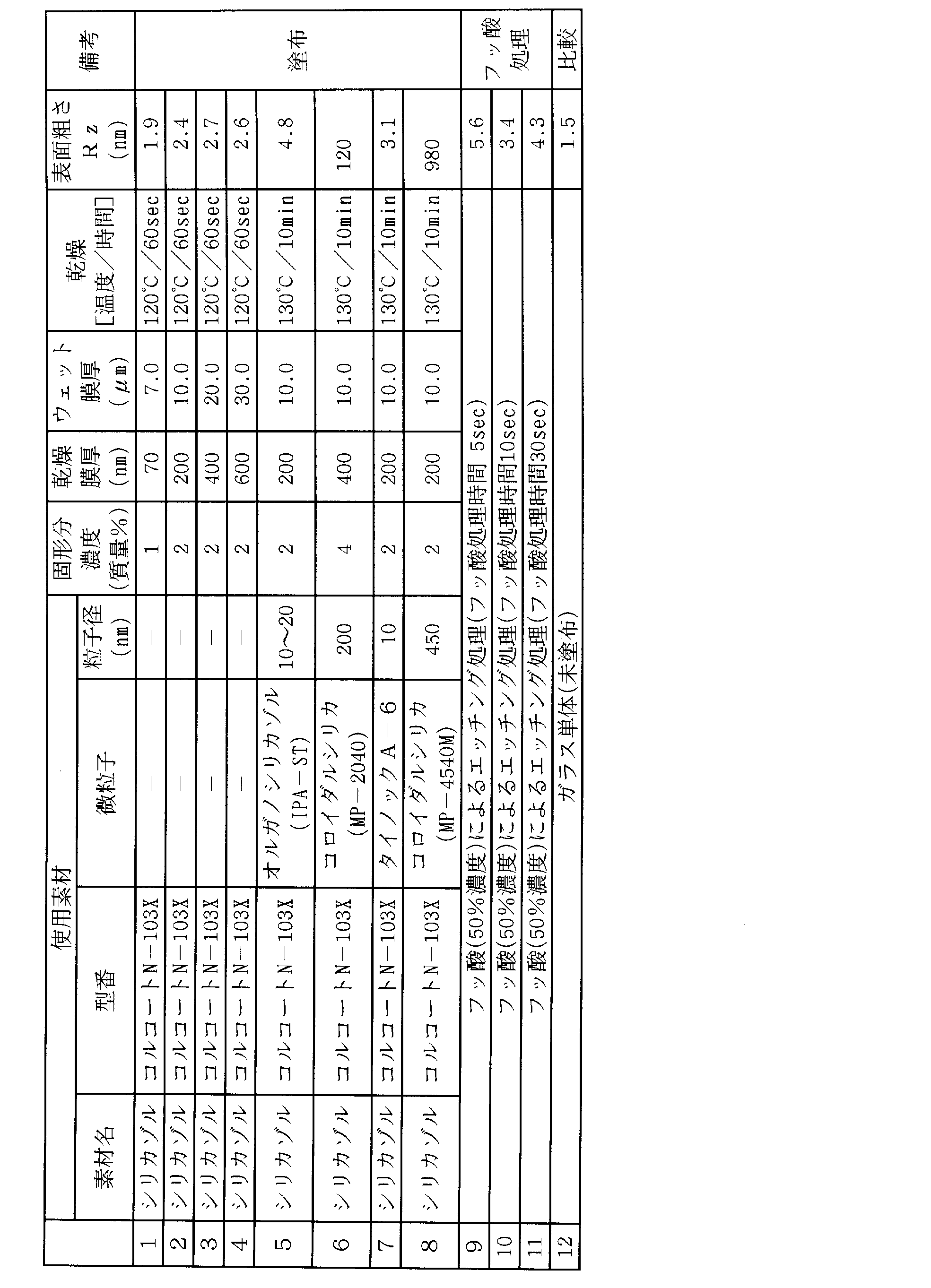
- Example 1 First, a coating composition (composition, solid content) using a silica sol “Colcoat N-103X (manufactured by Colcoat Co., Ltd.)” shown in Table 1 as a surface treatment, using the prepared thin film glass cut to A4 size. Samples 1 to 8 were prepared by preparing 1 to 8 (concentrations shown in Table 1), applying them with a wire bar, and performing drying treatment. In addition, about the application layer (surface treatment), the solid content density
- samples 9 to 11 were prepared by subjecting the thin film glass to surface treatment (treatment time 5 to 30 seconds) by means of immersing the thin film glass in a hydrofluoric acid (50%) solution.
- the size of the surface etching treatment with hydrofluoric acid was 50 ⁇ 100 mm.
- Table 1 shows the results of measuring the surface roughness of each sheet sample prepared above.
- Sample 12 was an untreated thin film glass.
- the surface roughness is an analysis value obtained by the AFM measuring device described above, and the analysis was performed with a three-dimensional (surface) evaluation, and the evaluation measurement area area was 5 ⁇ m square.
- the evaluation piece n 2 was shown as an average value. For reference, Ra value was also measured.
- Silica sol Colcoat Co., Ltd .: Colcoat N-103X (SiO 2 content 2%)
- Organosilica sol Nissan Chemical Industries, Ltd. IPA-ST (SiO 2 content 30%) Colloidal silica: MP-2040 manufactured by Nissan Chemical Industries, Ltd. (SiO 2 content 40%) Colloidal silica: MP-4540M (SiO 2 content 40%) manufactured by Nissan Chemical Industries, Ltd. Titanium oxide fine particles: Taki Chemical Co., Ltd. Tainoc A-6 (TiO 2 content 6%)
- the untreated glass has a surface roughness Rz of 1.5 nm, whereas the surface treated Rz increases the roughness to about 2 nm or more in Rz, and the treatment shows the effect of the surface treatment.
- Example 2 Using the samples 1 to 12 prepared in Example 1, the blocking characteristics of each sample were evaluated (substitute) by the following method. The following two types of evaluation were performed.
- Test 1 An untreated thin film glass is fixed on a horizontal base, and the prepared sample is placed on the glass so that the treated surface is in contact with the untreated glass surface, and a weight of 300 g in mass (diameter ⁇ 30 mm) is placed thereon. The load was applied for 1 minute, the weight was removed, and the contact unevenness that occurred when peeling was determined. That is, a portion (area) adhered within a diameter of ⁇ 30 mm to which a load was applied was visually determined, and the ratio of the portion to the portion to which the load was applied was subjected to sensory evaluation as an area ratio.
- Example 3 Using the apparatus shown in FIG. 1, a roll-to-roll application, drying, and winding test were performed.
- the thin film glass roll (prepared above) (thickness 70 ⁇ m, glass width 250 mm, glass length (winding length) 200 m) is set on the supply roll of the apparatus shown in FIG.
- the silica sol coating composition used in each of Samples 1, 2, 4, 5, and 8 was used as a coating solution so that the dry film thickness described in the table was obtained.
- Each was applied by an extrusion coater head. Thereafter, drying was performed in a dryer at 120 ° C. or 130 ° C. for the time indicated in the table, and the thin film glass on which the film was formed was wound up (Test Nos. 101 to 109).
- the take-up core used was a high-elastic body affixed on the surface in order to avoid the effect of terminal step transfer.
- the winding machine used the thing which has the position control mechanism (edge position controller mechanism (EPC)) which detects the position of a web edge in the upstream part, and tracks a winding edge position to the position.
- the line conveyance speed was 4 m / min.
- the initial tension and the tension were tapered in the transport / winding, and the tension was gradually reduced and wound.
- the initial tension and the winding length (corner) for applying the paper were fixed at 10% in all tests.
- the final tension was expressed as a percentage of the initial tension (taper), and the EPC control speed (response speed) is also shown in Table 1.
- the stability (linearity) of the end face edge position after winding was evaluated (an index of whether or not the core could be wound straight without any deviation).
- the linearity of the end is good when the fluctuation width is less than 2 mm, ⁇ , the fluctuation width is 2 mm or more and less than 4 mm, and the fluctuation width is 4 mm or more and less than 6 mm, ⁇ , the fluctuation width Those having a large diameter of 6 mm or more were evaluated as x.
- tests 110 to 113 For comparison, the results of a conveyance test using the same apparatus with the thin film glass not applied yet are also shown (tests 110 to 113).
- the thin film glass of the present invention in which fine irregularities were formed on the surface by applying a composition containing an aqueous silica sol was capable of being wound on a roll (without blocking or the like). No matter how much the tension, taper, etc. were devised, the winding core part was immediately broken and could not be wound.
- test no The thin film glass roll wound up at 102 was stored for 1 week under conditions of 23.5 ° C. and 55% RH, and then an unwinding test was performed. However, unwinding and unwinding were possible again. .
Landscapes
- Chemical & Material Sciences (AREA)
- Dispersion Chemistry (AREA)
- Composite Materials (AREA)
- Life Sciences & Earth Sciences (AREA)
- Engineering & Computer Science (AREA)
- Chemical Kinetics & Catalysis (AREA)
- General Chemical & Material Sciences (AREA)
- Geochemistry & Mineralogy (AREA)
- Materials Engineering (AREA)
- Organic Chemistry (AREA)
- Winding Of Webs (AREA)
- Surface Treatment Of Glass (AREA)
- Laminated Bodies (AREA)
Abstract
本発明は、プラスチックシートや合紙等の挿入物なしでくっつきをなくし、ガラス単独での巻き取りを可能にすると共に、ガラスと搬送ロールとの密着を防止して、薄膜ガラスを搬送・巻き取りする工程を含む薄膜ガラスの製造工程をロールツーロールで行うことにあり、また薄膜ガラスを基材とした種々の薄膜デバイスの製造についても合紙等の挿入物なしにロールツーロールで行うことにある。本発明の薄膜ガラスは、前記薄膜ガラス同士を重ね合わせたとき、接触面に空隙をもたせる様表面処理されたことを特徴とする。
Description
本発明は、プラスチックシートや合紙等の挿入物なしで薄膜ガラス同士のくっつきをなくし、薄膜ガラス単独での巻き取りを可能としたフレキシブルな薄膜ガラスに関する。
バリア性確保のために使用されるガラスはフレキシブルな機能をもたせるために、ガラスの薄肉化が進んでいる。
しかしながら、ガラスフィルムを製造する際に、ガラスフィルム同士を積み重ねたり、また薄膜ガラスの場合ロールに巻き取ると、ガラス同士が密着し表面に傷が付いたり、ブロッキングを起こしてしまう。これを防ぐために、ガラスの場合には、プラスチックフィルムを重ね合わせ間に挟んだ状態でガラスフィルムを巻き取っている(例えば、特許文献1、特許文献2)。
また、高バリア性かつフレキシブル性をもたせるためには、ガラスフィルムを樹脂でラミネートしなければ充分な強度が得られない(特許文献3、特許文献4)。
更に積層したガラス同士のブロッキング防止には、合紙を挿入したり(特許文献5、特許文献6)、また、粉を撒く(特許文献7)等の手段がとられている。
本発明の目的は、プラスチックシートや合紙等の挿入物なしでフレキシブルな薄膜ガラス同士のくっつきをなくし、ガラス単独での巻き取りを可能にすると共に、ガラスと搬送ロールとの密着を防止して、薄膜ガラスを搬送・巻き取りする工程を含む薄膜ガラスの製造工程をロールツーロールで行うことにある。また、薄膜ガラスを基材とした種々の薄膜デバイスの製造についても合紙等の挿入物なしにロールツーロールで行うことにある。
本発明の上記課題は以下の手段により達成される。
1.厚み30~150μmの薄膜ガラスであって、前記薄膜ガラス同士を重ね合わせたとき、接触面に空隙をもたせる様表面処理されたことを特徴とする薄膜ガラス。
2.前記表面処理された薄膜ガラス表面を十点表面粗さ(Rz)で表したとき、Rzが2nm以上であることを特徴とする前記1に記載の薄膜ガラス。
3.薄膜ガラス表面への前記表面処理が、前記薄膜ガラス表面への、水性シリカゾルを含有する組成物の塗布・乾燥による被膜の形成であることを特徴とする前記1または2に記載の薄膜ガラス。
4.前記水性シリカゾルを含有する組成物が、無機酸化物微粒子を含有することを特徴とする前記3に記載の薄膜ガラス。
5.前記無機酸化物微粒子が、珪素酸化物であることを特徴とする前記4に記載の薄膜ガラス。
6.前記水性シリカゾルを含有する組成物から形成される被膜が、耐熱性かつ透明な被膜であることを特徴とする前記3~5のいずれか1項に記載の薄膜ガラス。
7.前記3~6のいずれか1項に記載の薄膜ガラスの製造方法であって、前記薄膜ガラスへの前記水性シリカゾルを含有する組成物の塗布・乾燥がロールツーロール生産ラインの中で行われることを特徴とする薄膜ガラスの製造方法。
8.前記3~6のいずれか1項に記載の薄膜ガラスを巻き取ったことを特徴とする薄膜ガラスロール。
9.薄膜ガラスをロール状に巻き取る薄膜ガラスの巻き取り方法であって、前記薄膜ガラスが、薄膜ガラス同士を重ね合わせたとき、接触面に空隙をもたせるように表面処理されていることを特徴とする薄膜ガラスの巻き取り方法。
薄膜ガラス同士の密着力を低下させる処理を行うことにより、薄膜ガラスを、プラスチックシートや合紙等の挿入物なしで、ガラス単独で巻き取り可能とし、また、ガラスと搬送ロールとの密着を防止して、薄膜ガラスを搬送・巻き取りする工程を含む薄膜ガラスの製造をロールツーロールで行うことを可能とする。また、薄膜ガラスを基材とした種々の薄膜デバイスの製造についてもロールツーロールで行うことを可能とする。
以下本発明を実施するための形態について詳細に説明する。
本発明は、フレキシブルな薄膜ガラスであって、前記薄膜ガラス同士を重ね合わせたとき、接触面に空隙をもたせるよう表面処理を行った薄膜ガラスに関する。
ガラスは一般的に知られているように、有機高分子等に比べ凝集エネルギー密度、また自由体積分率等も小さいことからガスバリア性に優れている。また、透明性が高いことから光学的な用途に非常に適している。しかし、無機物質であるため脆いことが最大の欠点であり、強度を確保するため、厚い剛性の高い基板として用いられている。
これに対し、薄膜ガラスとは、厚みが、200μm以下、好ましくは、30~150μmの極めて厚みが薄いガラスをいい、薄膜であることによって可撓性を有し、曲げられることが特徴であり、例えば、ロール状に巻き取ることも可能である。
例えば、100μmの厚みをもつ薄膜ガラスの場合曲率半径として100mm以下の曲げが可能である。
しかしながら、ガラスの表面の平滑性は、その製法によっても異なるが、表面粗さ(十点平均粗さ)Rzで表すと1.5nmレベルに達する平滑な鏡面である。これにより、ガラス同士を重ね合わせたガラス同士の面接触環境では境膜の空気が抜けることにより容易に貼り付く所謂ブロッキング現象を起こしてしまう(実際には全面が貼り付くのではなく部分的にブロッキングする)。
従って、薄膜ガラスの場合でも全く同様であり、例えば、巻きとりを単独で行うと、薄膜ガラス同士が重なった接触面において境膜の空気が抜けることでくっつきを起こし所謂ブロッキング現象を起こし、破断、また表面に損傷を与えてしまう。これは巻き取りの場合は勿論のこと、薄膜ガラスを重ねて配置する場合も同様である。
従って、前記特許文献3においては、さらにフレキシブル性をもたせるためもあるが、薄膜ガラスを樹脂でラミネートしている。また、積層したガラス同士のブロッキングを防止するために、前記特許文献5、6等の記載のように、合紙を挿入することはよく知られている。また、特許文献7に記載の如く粉を撒く等の方法がとられている場合もある。
薄膜ガラスの場合、ロール形態に巻き取ったり、ロール形態で保管したりすることが可能であるが、例えばPETフィルム等の合紙を用いてこれを薄膜ガラスと一緒にロールに巻きとることがブロッキング防止するため必要となっている。
本来巻き取りは、層間の境膜としての空気をなるべくなくして、層間の滑りを極力抑えることが要求される。これは長尺の巻き取りを行う上で巻きずれ、巻き締まり抑制のため必要である。しかし、これはフィルム等の樹脂または紙の場合に云えることであり、フィルムは靱性にも富み、また、剛性率も低めであり、巻き取り張力の幅手位置での偏在による破断等が発生しない前提でなし得るものである。
前記のように、十点平均粗さRzで表すと1.5nmレベルに達するガラスを用いた場合、ガラスを重ねると通常はくっついてしまう(比較的簡単に剥がれる)。従って、薄膜ガラスをロールに巻き取ったり、多数枚重ね合わせたりすると、ガラス同士が貼り付きを起こし簡単に剥がすことが出来ず、所謂ブロッキング現象を起こしてしまう。
薄膜ガラス表面は、表面粗さを十点平均粗さRzで表すと1.5nmレベルに達する平滑な鏡面であるため、分子間力が強く働く、分子同士が0.5nm(5Å)以下に接近するので、ガラス表面同士において分子間力が働く領域となり、強くくっついて(貼り付いて)しまう。
例えば、表面が粗い基材でも基材間に水滴を垂らすと強く貼り付くのは、基材同士の接触面に空隙(境膜の空気)がなくなり基材表面の分子と水の分子間に引き合う力が働いて貼りつくのであり、分子間力自体は弱い力であるが、広い面積でこれが作用することで基材同士は強い力でくっついてしまう。
この様に境膜の空気(空隙)がなくなり、分子間力が強くなることで、薄膜ガラス同士が貼り付きやくすなるため、ブロッキングを起こしたり、またずれが起こらず傷が表面についたりすると考えられる。
また、薄膜ガラスを巻きとり、搬送する工程を考えてみると、巻き取りはシビアに種々の応力が掛かる現象であり、搬送に影響を与える因子として、ウェブ自体の張力、その幅手位置での偏在、侵入位置、角度ずれ変化(侵入するウェブの位置ずれや角度ずれを補正する制御機能を持たせる)等いろいろの要因が挙げられる。
ガラスは脆性材料であり、従って前記のくっつきに加えて、靱性自体が小さいことから、そのエッジ(端部)の状態にも強度自体は左右されるが、エッジへの応力集中で容易に破断する特性がある。
また、くっつきや貼り付きのためにロールに巻き取る場合等、適度な巻き締まりが起こらずこの面でも巻き取り方向に張力が偏在することによる破断等が起きてしまう。
靭性(じんせい)とは、材料の粘り強さをしめす性質であり、材料に力を加えると初めは弾性的に変形し、その後、塑性(外力を除いても元の形に戻らない性質)的に変形し、ついに破断するが、この間に費やされたエネルギーが大きいほど靭性が大きいという。ガラスは靱性自体が小さいことから、材質の粘り強さがなく、外力によって破壊されやすい性質をもっている。
実際の巻き取りにおいては、自身の位置ずれ要素が生じると、層間のブロッキングが起こっている状況下ではガラスエッジへの集中応力が生じ、すぐ破断しやすい。
以上の薄膜ガラスにおける課題を防止するために、本発明においては、前記薄膜ガラス同士を重ね合わせたとき、接触面に空気境膜(空隙)を形成させる手段を設けることが課題解決に繋がると考え以下の手段を見出した。空気境膜は重ね合わせたガラス間の微細な空隙から構成され、空隙とは薄膜ガラス同士を重ね合わせたとき、ガラス間に形成される、微少な非接触領域(空間)のことをいう。
即ち、前記薄膜ガラスの接触面における前記空隙は、薄膜ガラス表面に、表面処理を行って微細な凹凸構造を形成させることにより形成され、且つ、重ね合わせた薄膜ガラス間に形成されるこの微細な空隙は、少なくとも重ね合わせた薄膜ガラス表面間を、前記分子間力が強く働く領域を超えた平均2nm以上の距離隔てることが好ましい。空隙の大きさは、従って空隙により隔てられたガラス間の距離がこれに相当する。重ね合わせた面の一方が鏡面でありもう一方が凹凸面であるときには空隙の大きさは凸部と凹部の差(凸部の高さ)がこれに相当する。
本発明において前記の空隙は、好ましくは2nm以上であり、更に好ましくは前記分子間力が全く作用しない40nm以上であり、また、好ましくは200nm以下である。200nm以上の空隙をもたせるよう表面処理した薄膜ガラスは、薄膜ガラス自体の透明性が光散乱により妨害され、光の透過性が損なわれる。
この空隙(距離)を確保するため、本発明においては、薄膜ガラスを表面処理することによって、表面粗さを十点平均粗さRzで定義したとき、Rzが2nm以上、好ましくは2.5nm以上の表面とすることが好ましい。更に好ましくは、Rzは40nm以上であり、また、200nm以下が好ましい。200nm以上の場合光の散乱が起こり薄膜ガラスの透明性が低下する。
厳密にいえば、表面粗さを評価する数値のうち十点平均粗さRzで定義される数値は空隙の大きさそのものではないが、表面同士の摩擦やくっつきを評価するときに長周期の凹凸を表す表面粗さRzはよくこれに相関する。一方Raについてはより微細な凹凸に対応する表面粗さである。
十点平均粗さRzとは基準面積を抜き取り、抜き取り部分の最も高い山頂から5番目までの山頂の標高の絶対値の平均値と、最も低い谷底から5番目までの谷底の標高の絶対値の平均値の和であることから、前記空隙を近似するものと考えている。
従って、薄膜ガラス表面の表面粗さをこのような十点平均粗さとすることで、薄膜ガラス同士を重ね合わせたとき空隙が確保され、接触面において形成される空隙(空気境膜)はこの表面粗さ(十点平均粗さ)を反映する。
十点平均粗さ(Rz)とは、JIS B 0601に規定された数値であり、例えば、触針法もしくは光学的方法等が挙げられるが、本発明においては、原子間力顕微鏡(AFM)を用いたエスアイアイテクノロジー製測定装置を用いた。
ステーション(コントローラー):NanoNaviII
ユニット(測定部):SPA-400
カンチレバー:SI-DF20
測定モードはDFM(ダイナミックフォースモード)
薄膜ガラス表面に施される表面処理としては、例えば、薄膜ガラスをエッチング(ドライ、ウェット)等することで表面を荒らすことによってもよい。また、サンドブラスト等による表面加工をもちいてもよい。これらの表面処理によっても本発明の効果を得ることができる。
ステーション(コントローラー):NanoNaviII
ユニット(測定部):SPA-400
カンチレバー:SI-DF20
測定モードはDFM(ダイナミックフォースモード)
薄膜ガラス表面に施される表面処理としては、例えば、薄膜ガラスをエッチング(ドライ、ウェット)等することで表面を荒らすことによってもよい。また、サンドブラスト等による表面加工をもちいてもよい。これらの表面処理によっても本発明の効果を得ることができる。
本発明において、薄膜ガラス表面に施される表面処理として、薄膜ガラス上に水性シリカゾルを含有する組成物を塗布・乾燥して形成される被膜(層)を設けることが好ましく、この被膜は耐熱性かつ透明な被膜であることが好ましい。ここで耐熱性とは200℃の温度に晒しても被膜にヘイズ等を生じず透明度に変化がないことをいう。
表面処理によって、薄膜ガラス表面にこの様な組成物を塗布することによって凹凸構造を形成することで、以降、合紙の使用、また、ラミネート等を行わずに、搬送、巻き取り等のハンドリングを容易に行うことが可能である。
本発明の水性シリカゾルを含有する組成物に用いる水性シリカゾルについて以下説明する。
表面処理として、薄膜ガラス上に形成される被膜(層)を形成するためのコーティング組成物の構成成分としての水性シリカゾルについて説明する。水性シリカゾルは、リチウムシリケート及び/又は加水分解性ケイ素化合物を水系で分散あるいは加水分解(また重縮合)により得られる均一、かつ、安定した水性シリカゾルである。ここに、水系で分散あるいは加水分解するという意味は、本発明組成物全体の10%以下の有機溶媒が存在してもよいということを意味する。
リチウムシリケート及び/又は加水分解性ケイ素化合物から水系で均一、かつ、安定した水性シリカゾルを調製する手段の1つとしては、本発明組成物全体に有機溶媒が10%以下となる量の有機溶媒にリチウムシリケート及び/又は加水分解性ケイ素化合物を溶解し、触媒の存在下に加水分解する方法がある。
加水分解は、有機溶媒にリチウムシリケート及び/又は加水分解性ケイ素化合物を予め溶解させておくことにより、加水分解時に水との急激な反応が阻止され、シリカ(SiO2)の析出や反応生成物の白濁化が阻止され、均一、かつ、安定した水性シリカゾルが得られる。この反応において、有機溶媒が逆に多くなっても加水分解反応は同様に生起するため、有機溶媒量の管理は重要である。一般に、最終組成物中に有機溶媒が10%以下になるように管理する。使用される有機溶媒としてはメタノール、エタノールなどのアルコール類が好ましい。
水系で均一、かつ、安定した水性シリカゾルを調製する他の手段としては、有機溶媒を使用しない方法がある。この場合、水中に触媒を均一に溶解した溶液を調製し、この中にリチウムシリケート及び/又は加水分解性ケイ素化合物を添加することによって得られる。
本発明で使用されるコーティング組成物に用いられる加水分解性ケイ素化合物は、下記一般式(1)で示されるものが好ましい。
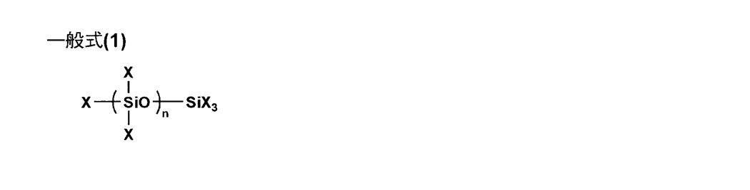
式中、Xは、ハロゲン原子、炭素原子数1~8のアルコキシ基、アルコキシアルキル基、アルキル基およびアリール基を表し、これらは同一であってもことなっていてもよい。nは0または正の整数を表す。
上記一般式(1)で示される加水分解性ケイ素化合物は、式中nが1~10のものが好ましい。具体的には四塩化ケイ素(SiCl4)、テトラエチルシリケート(Si(OEt)4)、テトラメチルシリケート(Si(OMe)4)及びこれらアルキルシリケートの縮合物例えばテトラエチルシリケートの5重体(商品名エチルシリケート40、コルコート(株)製)などを挙げることができる。
本発明において、コーティング組成物中の加水分解性ケイ素化合物の使用量は、全コーティング組成物中シリカ換算で固形分として1~10質量%の範囲の使用が好ましい。
前記リチウムシリケート及び/又は加水分解性ケイ素化合物を、分散あるいは加水分解する方法は以下のように行う。即ち、所定量の有機溶媒にリチウムシリケート及び/又は加水分解性ケイ素化合物を、所定の固形分濃度になる量を溶解して均一な溶液とし、触媒の存在下に分散あるいは加水分解する。
また、有機溶媒を使用しない場合は、水と触媒の均一溶液に、リチウムシリケート及び/又は加水分解性ケイ素化合物を所定の固形分濃度になる量を添加し、分散あるいは加水分解する。分散又は加水分解は、酸またはアルカリ触媒の存在下に、所望の加水分解率に要求される量の水を添加して行う。
分散又は加水分解用の触媒としては、例えばLiOH,NaOH,KOHなどの塩基性の水酸化物触媒があり、ケイ素化合物に対して0.01~10質量%が使用される。使用する触媒としては、水性シリカゾルと後述する水性官能基含有重合体が反応して複合体を形成した系において、該複合体の分解やシリカの析出などを発生させないようにするために塩基性の触媒が好ましい。
分散又は加水分解の反応温度は、室温から50℃の温度で十分であり、また、反応時間は反応温度、触媒量により異なるが、一般には1~24時間である。以上の分散及び加水分解反応によりリチウムシリケート及び/又は加水分解性ケイ素化合物から水性シリカゾルを得ることができる。
また、本発明において、水性シリカゾルは分散及び加水分解により調製されるため、水性シリカゾルの末端基にはOH基が含まれ、経時的に不安定となる。これを安定化する意味においても、次に述べる水性官能基含有重合体が使用されることが好ましい。
次に、接触面に空隙をもたせるための被膜を形成するコーティング組成物の構成成分である水性シリカゾル等と反応して化学的複合体を形成する水性官能基含有重合体について説明する。本発明において水性官能基含有重合体とは、水溶性または水分散性の重合体を包含する。
水性官能基含有重合体は、例えば水分散性ポリマーであり、水性シリカゾルとの相溶性がよく、塗布面が合成樹脂である場合には、接着性、透明性に優れた塗膜を形成することができる組成物を与える。又、前記したように水性シリカゾルは、末端OH基を有するために経時的に変化しようとするが、この経時的不安定化を防止するために水性官能基含有重合体が使用される。
水性官能基含有重合体としては、例えばエステル結合をもった水分散性のポリエステルが典型的なものである。即ち、エステル結合をもったポリエステル重合体は、水性シリカゾルを構成するポリシロキサン中の未反応の加水分解基やシラノール基(Si-OH)などと化学反応、あるいは水素結合するエステル結合、その他の官能基(水酸基やカルボキシル基など)を有するため、水性シリカゾルと反応して化学的複合体を形成する。
水分散性のポリエステルの具体例としては、市販のバイロナール(東洋紡(株)製)などが使用され、これらの数平均分子量は1,000~50,000、好ましくは10,000~20,000のものである。
水性官能基含有重合体は、上記の水分散性ポリエステルに限定されるものではなく、従来公知の水溶性または水分散性エマルジョンタイプのコーティング剤であって、かつ、前記水性シリカゾルと反応することができる重合体が使用できることはいうまでもない。この種の水性官能基含有重合体の具体例としては、ビニルアルコール系ポリマー、エチレングリコール系ポリマー、ポリエステルポリオール系ポリマー、ポリエーテルポリオール系ポリマー、水性ウレタン樹脂などがある。
本発明において、前記水性官能基含有重合体は、本発明の全コーティング組成物中0.1~5質量%の割合で使用すれば十分であり好ましい。
本発明は更に、界面活性剤を配合してもよい。界面活性剤の配合により、表面張力が下げられ、濡れ性が向上するため、被塗装面に対する接着性を向上させる。
界面活性剤としては、特に限定はないが非イオン性の界面活性剤の使用が好ましい。これには、例えば、ポリオキシエチレンアルキルエーテル、ポリオキシエチレンポリオキシプロピレンアルキルエーテル、ポリオキシエチレンアルキルフェニルエーテル、ソルビタン脂肪酸エステル、ポリグリセリン脂肪酸エステル、ポリエチレングリコール脂肪酸エステル、シリコーン系、フッ素系(パーフルオロアルキルエチレンオキシド付加物、パーフルオロアルキルポリオキシエチレンエタノール、フッ素化アルエステル)などの非イオン性界面活性剤が好ましいものとして挙げることができる。
本発明において、特に非イオン性界面活性剤として、その構造としてSi-C結合を有する側鎖変性コポリマー、またはSi-O-C結合の末端変性コポリマーを含むシリコーン系およびパーフルオロアルキル基を含むフッ素系界面活性剤が好ましい。本発明において、前記した界面活性剤は、全組成中0.05~5質量%の割合で使用すれば十分である。
また、本発明においては、前記水性シリカゾルを含有する組成物中に無機酸化物微粒子を含有することが好ましい。
無機酸化物微粒子は、その粒径が平均で1μm以下であり、好ましくは400nm以下、更に好ましくは200nm以下である。
粒径が1000nmを越えると、ガラス基材に対する密着性や耐擦傷性が十分でなく、透明性や親水性も十分でないことがある。なお、この粒径は、調製の容易さの点から、平均で通常5nm以上である。また、無機酸化物微粒子としては、通常、球状や粒状のものが用いられ、ここでいう球状には、真球状や楕円球状の他、これらが多少変形したものも含まれる。無機酸化物微粒子の最長径/最短径の比率は通常3/1~1/1である。
無機酸化物微粒子の種類については、適宜選択されるが、シリカ、アルミナ、酸化スズ、酸化アンチモン、酸化インジウムのような酸化物や、スズ-アンチモン複合酸化物、インジウム-スズ複合酸化物のような複合酸化物が好ましく用いられる。中でもシリカやアルミナが、親水性に優れ、強度も高いことから、より好ましく用いられ、シリカが最も好ましい。無機酸化物微粒子は必要に応じてそれらの二種以上を用いることもできる。
酸化スズ、酸化アンチモン、酸化インジウムのような酸化物や、スズ-アンチモン複合酸化物、インジウム-スズ複合酸化物のような導電性金属酸化物を用いると、ガラス表面の帯電防止効果を向上させることができる。
無機酸化物微粒子は、固体状のものを用いてもよいし、水又は有機溶剤中に分散したゾル状のものを用いてもよいが、ゾル状のものを用いるのが好ましい。無機酸化物微粒子の市販品の例としては、ゾル状のシリカであれば、日産化学工業(株)から販売されているスノーテックス20、スノーテックスCのような「スノーテックス」シリーズや、オルガノシリカゾル IPA-ST、オルガノシリカゾル MIBK-STのような「オルガノシリカゾル」シリーズなどが挙げられ、ゾル状のアルミナであれば、日産化学工業(株)から販売されているアルミナゾル-520のような「アルミナゾル」シリーズなどが挙げられる。また、固体状のシリカであれば、日本アエロジル(株)から販売されているAEROSIL 50、AEROSIL 130のような「AEROSIL」シリーズや、東ソーシリカ工業(株)から販売されているE 200のような特殊シリカなどが挙げられる。
尚、微粒子の粒径は、透過型電子顕微鏡、H-1700FA型(日立製作所社製)を用いて10000倍の倍率で観察した後、得られた画像について無作為に粒子を100個選び、画像処理ソフト(WINROOF)を用いて一個毎の粒径(円換算粒径)を解析し、それらの単純な数平均値を求めることができる。
組成物中の加水分解性有機珪素化合物と無機酸化物微粒子の量比は、両者の合計量を100質量部として、前者に対し、後者が20~80質量部である。後者が20質量部あれば充分親水性であり塗膜の均一性がより向上する。一方、後者が80質量部以内であれば、ガラス基材に対する密着性も十分であり、耐擦傷性も向上する。
本発明においては、水性シリカゾルを含有するコーティング組成物を、薄膜ガラス上に塗布、乾燥することで、表面に微細な凹凸構造を形成し、所定の表面粗さ(例えばRzで2nm以上)を有する、耐熱性かつ透明な被膜が薄膜ガラス上に形成される。
ガラスへの濡れ性を考慮すると、水系のゾルではなく有機溶剤をもちいた溶剤系での塗布を行うことも好ましい。
水性シリカゾルを含有する組成物による被膜を薄膜ガラス上に形成するためのコーティング組成物の塗布方法は特に限定はなく、例えば、スライド塗布、スピンコート塗布、ディップ塗布、エクストルージョン塗布、ロールコート塗布、スプレー塗布、グラビア塗布、ワイヤバー塗布、ブレード塗布、エアナイフ塗布等が挙げられる。必要に応じて、これらの塗布方法の中から選択することが可能である。
流量規制型では高精度の塗工膜厚が管理しやすく、減圧押し出し、スライドホッパー等を用いることが出来る。
また後計量系型の塗布、ワイヤバー塗布、マイクログラビア、ロールコーター(リバース含む)エアドクター、またグラビア塗布等を用いることも可能である。
中でも、塗布面が傷つきやすいガラスであるため、接触損傷を避ける観点から、エクストルージョン塗布、押し出し塗布(所謂スロットダイ)等が好ましく、高品質な塗膜形成が可能である。
図1に、薄膜ガラス上に水性シリカゾルを含有する組成物を塗布、乾燥処理を行って、所定の表面粗さをもつ微細な凹凸構造を表面に形成し、フレキシブルな薄膜ガラスをロールツーロールで製造する工程の一例を概略模式図で示した。
所定の長さに巻き回された薄膜ガラス101の製造工程を示す。製造工程は、薄膜ガラス基材供給工程(アンワインダ)1と、水性シリカゾルを含有する組成物を塗布するためのコーター2を有する塗布工程と、ドライヤー3からなる乾燥工程及び巻き取り工程(ワインダ)4を有している。
薄膜ガラス基材供給工程3は、合紙と一緒にロール状に巻かれた薄膜ガラスロール原反を取り付けた巻き出しロールから、駆動手段(不図示)により、長尺状の薄膜ガラス基材101が繰り出され、合紙は別に巻き取られ(不図示)分離されて、薄膜ガラス単体でコーター2へ搬送(図中矢印方向)される。
水性シリカゾルを含有するコーティング組成物はコーター2において、薄膜ガラス上に供給される。コーティング組成物は塗布液貯蔵タンクから例えば超音波脱気装置等の脱気装置を通して供給される(いずれも不図示)。加熱装置等を使用してもよい。また塗布液貯蔵タンクは脱気装置で脱気する時の塗布液の温度を制御する温度制御系等を配設することが好ましい。
脱気装置は塗布液貯蔵タンクから送液管を介して送られる塗布液を脱気する装置であり、脱気装置としては特に限定はなく、例えば超音波脱気装置、加熱脱気装置、減圧脱気装置、特開平11-209670号公報に記載のごとく、脱気用中空糸膜による脱気方法、特開2004-181403号公報に記載の気-液分離膜モジュール等が挙げられ、必要に応じて選択することができる。
塗布工程では、コーター2と基材101を巻き回し保持するバックアップロール201が使用される。尚、コーター2には水性シリカゾルを含有するコーティング組成物の温度を維持するために温度制御手段(不図示)を配設することが好ましい。本図は、コーターとしてエクストルージョン塗布方式のコーターの場合を示している。
水性シリカゾルを含有する組成物の塗布時の温度は、これを構成している溶媒の沸点に対して20℃以上低いほうが、コーティング組成物の溶媒の蒸発により塗布液の濃度上昇、粘度上昇が生じず安定した膜厚の塗布ができるため好ましい。
ドライヤー3からなる乾燥工程においては、コーター2により薄膜ガラス上に塗布されたコーティング組成物のウェット膜から溶媒を除去し、これを乾燥して、耐熱性かつ透明な皮膜として薄膜ガラス基材上に形成させる工程である。
乾燥工程においては、ここでは図示していないが、例えば活性光線、例えば紫外線等を照射してもよく、ゾルからゲルへの転化を促進させることができる。必要な活性光線の照射量としては、硬化効率又は作業効率の観点から0.1秒から10秒がより好ましい。また、これら活性光線照射部の照度は0.05W/m2から0.2W/m2であることが好ましい。
また、塗布直後の乾燥処理に、さらに別に付加的に熱処理を加えてもよい、乾燥のほか水性シリカゾルのガラスへの転化処理を促進させる。
これら水性シリカゾルにより形成される層の厚みは乾燥膜厚で、5nm~5μmが好ましく、より好ましくは、20nm~500nmである。
塗布・乾燥後、幾つかのガイドローラーを介し、巻き取り工程(ワインダ)4において、乾燥が終了した、表面に微細な凹凸構造が、水性シリカゾルを含有する被膜により形成された薄膜ガラスが、合紙等を用いずに、単独の状態でロール形態に巻き取られる。
塗布・乾燥後は、表面に微細な凹凸構造が形成され、また、重ねられたときも基材間に空隙を有する構造となるため、塗布乾燥後は、搬送工程(ガイドロール間を搬送されるが)についても、くっつき、貼り付きがなく、また、ウェブ自体の張力やその幅手の偏在、侵入位置や、角度ずれの変化等に対して、侵入するウェブの位置ずれや角度ずれを補正する制御機能により、制御機能が充分に働くことになり、前記のくっつきに加えて、薄膜ガラス端部(エッジ)への応力集中も緩和されるので、ガラスエッジでの破断も起こりにくい。また、巻き取った後にも基材ロールがブロッキングを起こすことがない。
尚、薄膜ガラスの搬送工程におけるガイドローラー等のロールについてはガラス面に傷を付けにくい樹脂、ゴム等弾性系の材質を選択することが好ましい。
このように塗布・乾燥により形成される前記の被膜は、耐熱性かつ透明な皮膜であり、前記被膜が形成された薄膜ガラスは、薄膜ガラス同士を重ね合わせたとき、接触面に空隙をもたせる様、表面処理されており、ロール状に巻き取る場合でも合紙等を用いず単独で巻き取ることが出来、また、ロールとして保管された場合にも、ブロッキング、また破断等を起こすことなく。これを基板として種々の薄膜デバイス(例えば有機EL素子、光電変換素子等)のロールツウロールでの製造に用いることが出来る。
また、搬送、巻き取り中にウェブはどうしても自身が自然に蛇行したりするので、幅手位置制御により、幅方向への規制力が生じるが、ガラスの表面が平滑で貼り付きがよいと、これが制御力や自然蛇行力とぶつかり、破断(割れ)を起こすが、本発明の空隙構造を表面に形成した薄膜ガラスは、滑り性が確保されるために破断を起こすことがない。
本発明に係る薄膜ガラスはロールツウロールでハンドリンクできることが特徴であるが、ロール搬送するときを考慮すると、ウェブの蛇行に対する制御への幅手位置制御においてくっつきや破断が起きないこと等、薄膜ガラスのロール幅としては20mm~2000mmの範囲が好ましく対応が可能である。
尚、断るまでもないが、本発明の薄膜ガラスは両面に水性シリカゾルを含有する組成物から形成される被膜(層)を有してもよい。本発明は、表面処理された薄膜ガラスを用いる巻き取り方法でもあるが、本発明の薄膜ガラスは、枚葉での取り扱いにおいても全く同様にブロッキングや、破断を防止する効果は同様であり、本発明はロール形態での取り扱いにのみ限定されるものではない。
以下、実施例により本発明を具体的に説明するが、本発明はこれにより限定されるものではない。
(薄膜ガラス)
薄膜ガラスロール原反は、溶融釜から作成した長尺のガラスシート(厚み70μm)を炭酸ガスレーザーで250mm幅にカットして合紙(ポリエチレンテレフタレートフィルム)とともに200m長で巻き芯(巻き芯径150mm)にロール状に巻きとったものを使用した。ガラスを亀裂進展切断する炭酸ガスレーザー切断技術は、その切断断面のマイクロクラックも極小化でき、切断したガラス自体の破断強度をつよく維持できることは公知である。
薄膜ガラスロール原反は、溶融釜から作成した長尺のガラスシート(厚み70μm)を炭酸ガスレーザーで250mm幅にカットして合紙(ポリエチレンテレフタレートフィルム)とともに200m長で巻き芯(巻き芯径150mm)にロール状に巻きとったものを使用した。ガラスを亀裂進展切断する炭酸ガスレーザー切断技術は、その切断断面のマイクロクラックも極小化でき、切断したガラス自体の破断強度をつよく維持できることは公知である。
実施例1
先ず、作成した薄膜ガラスをA4サイズにカットしたものを用いて、表面処理として、表1に示すシリカゾル「コルコートN-103X(コルコート(株)製)」を用いたコーティング組成物(組成、固形分濃度を表1に示した)1~8を調製し、ワイヤバーにて塗布、乾燥処理を行って試料1~8を作成した。なお、塗布層(表面処理)についてはコーティング組成物の固形分濃度、また、ワイヤバー番手調整によりウェット膜厚を変化させ、所望の乾燥塗布膜厚を確保した。また乾燥温度、時間についてはそれぞれ表1中に条件を記載した。
先ず、作成した薄膜ガラスをA4サイズにカットしたものを用いて、表面処理として、表1に示すシリカゾル「コルコートN-103X(コルコート(株)製)」を用いたコーティング組成物(組成、固形分濃度を表1に示した)1~8を調製し、ワイヤバーにて塗布、乾燥処理を行って試料1~8を作成した。なお、塗布層(表面処理)についてはコーティング組成物の固形分濃度、また、ワイヤバー番手調整によりウェット膜厚を変化させ、所望の乾燥塗布膜厚を確保した。また乾燥温度、時間についてはそれぞれ表1中に条件を記載した。
尚、試料5~8ではコルコートN-103Xにそれぞれ表1に示す微粒子を混合・分散(ホモジナイザー)して用いた。微粒子とコルコート固形分の質量比で1:1となるよう混合した。
また、別に、薄膜ガラスをフッ酸(50%)液中に浸漬させる手段により薄膜ガラスに表面処理(処理時間5~30秒)を行って試料9~11を作成した。なお、フッ酸による表面のエッチング処理サイズは、50×100mmサイズとした。
以上にて作成した各枚様試料について、表面粗さを測定した結果を表1に示した。尚、未処理の薄膜ガラスを試料12とした。
表面粗さに関しては、前述AFM測定器での解析値であり分析は3次元(面)評価とし、その評価測定面積エリアは5μm角とした。評価ピースn=2枚の平均値で示した。参考のためRa値についても測定した。
以上において、
シリカゾル:コルコート株式会社製:コルコートN-103X(SiO2含有量2%)
オルガノシリカゾル:日産化学工業株式会社製 IPA-ST(SiO2含有量30%)
コロイダルシリカ:日産化学工業株式会社製 MP-2040(SiO2含有量40%)
コロイダルシリカ:日産化学工業株式会社製 MP-4540M(SiO2含有量40%)
酸化チタン微粒子:多木化学株式会社 タイノックA-6(TiO2含有量6%)
未処理のガラスが表面粗さRzで1.5nmであるに対し、表面処理を行ったものではいずれもRzで略2nm以上と粗さを増しており処理が表面処理による効果を示している。
シリカゾル:コルコート株式会社製:コルコートN-103X(SiO2含有量2%)
オルガノシリカゾル:日産化学工業株式会社製 IPA-ST(SiO2含有量30%)
コロイダルシリカ:日産化学工業株式会社製 MP-2040(SiO2含有量40%)
コロイダルシリカ:日産化学工業株式会社製 MP-4540M(SiO2含有量40%)
酸化チタン微粒子:多木化学株式会社 タイノックA-6(TiO2含有量6%)
未処理のガラスが表面粗さRzで1.5nmであるに対し、表面処理を行ったものではいずれもRzで略2nm以上と粗さを増しており処理が表面処理による効果を示している。
実施例2
実施例1で作成した試料1~12を用いて各試料のブロッキング特性について以下の方法で(代用)評価を行った。以下二種類の評価を行った。
実施例1で作成した試料1~12を用いて各試料のブロッキング特性について以下の方法で(代用)評価を行った。以下二種類の評価を行った。
試験1:
未処理の薄膜ガラスを水平な台上に固定しガラス上に、作成した試料を処理面が未処理ガラス面と接するように載置して、質量300gの錘(直径φ30mm)をその上に載せ、荷重を1分間かけ、錘を除去し、剥がした際に発生した密着ムラから判定した。即ち、荷重がかかった直径φ30mm内において貼り付いた部分(面積)を目視で判定し、荷重がかかった部分に対するその比率を面積率として官能評価した。
未処理の薄膜ガラスを水平な台上に固定しガラス上に、作成した試料を処理面が未処理ガラス面と接するように載置して、質量300gの錘(直径φ30mm)をその上に載せ、荷重を1分間かけ、錘を除去し、剥がした際に発生した密着ムラから判定した。即ち、荷重がかかった直径φ30mm内において貼り付いた部分(面積)を目視で判定し、荷重がかかった部分に対するその比率を面積率として官能評価した。
密着ムラの面積率
発生なし : ◎
10%以下 : ○
10%超、40%以下 : △
40%超 : ×
試験2:
未処理の薄膜ガラスを水平な台上に固定しガラス上に、作成した試料を処理面が未処理ガラス面と接するように載置するが、上側の試料を30mm角の大きさとして、それを指先で押さえながら滑らせようとした際の引っ掛かり度合いを以下の4段階で官能評価した。
発生なし : ◎
10%以下 : ○
10%超、40%以下 : △
40%超 : ×
試験2:
未処理の薄膜ガラスを水平な台上に固定しガラス上に、作成した試料を処理面が未処理ガラス面と接するように載置するが、上側の試料を30mm角の大きさとして、それを指先で押さえながら滑らせようとした際の引っ掛かり度合いを以下の4段階で官能評価した。
引っ掛かり
発生なし : A
僅かに引っ掛かり感あり: B
かなり引っ掛かる : C
簡単に動かない : D
以上の結果を表2に示した。
発生なし : A
僅かに引っ掛かり感あり: B
かなり引っ掛かる : C
簡単に動かない : D
以上の結果を表2に示した。
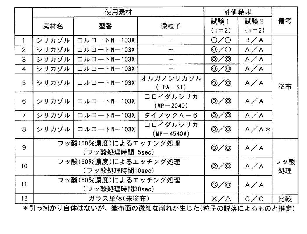
以上のように未塗布のガラスに比べ表面処理を行った本発明の試料は貼り付きに関して大きく改善されたことが判る。
実施例3
図1に示す装置を用いて、ロールツウロールでの塗布、乾燥、巻き取り試験を行った。
図1に示す装置を用いて、ロールツウロールでの塗布、乾燥、巻き取り試験を行った。
前記で作成した薄膜ガラスロール原反(厚み70μm、ガラス幅250mm、ガラス長(巻き長さ)200m)を、図1に示す装置の供給ロールにセットして、供給ロールから繰り出し(合紙を除きつつ)、表3に記載のように、薄膜ガラス上に、前記試料1、2、4、5、8でそれぞれ用いたシリカゾルコーティング組成物を塗布液として用いて表記載の乾燥膜厚となるよう、それぞれエクストルージョンコーターヘッドにより塗布した。その後、乾燥をドライヤー中120℃又は130℃で表記載の時間行ってのち、皮膜が形成された薄膜ガラスの巻き取りを行った(試験No.101~109)。
巻き取りコアは端末段差転写の影響を避けるべく、表面に高弾性体を貼ったものを使用した。また、巻き取り機は、その上流部にウェブエッジの位置を検出し、巻き取りエッジ位置をその位置に追従させる位置制御機構(エッジポジションコントローラー機構(EPC))を有するものを使用した。尚、いずれの場合もライン搬送速度は4m/minで行った。
また、薄膜ガラスの搬送適性を見るために、搬送・巻き取りには、初期張力と、張力にテーパをかけ、徐々に張力をおとし巻き取りを行った。初期張力とデーパをかける巻き取り長(コーナー)はいずれの試験にても10%と固定した。最終張力は初期張力に対する%で表示した(テーパ)、また、EPC制御速度(応答速度)についてもそれぞれ表1に示した。
また、巻き取り後の端面エッジ位置の安定性(直線性)についても評価した(コアに対してズレなく真っ直ぐ巻くことができたかの指標)。目視で、端部の直線性が変動幅2mm未満で良好なものを◎、変動幅2mm以上、4mm未満であるものを○、また、変動幅が4mm以上、6mm未満のものを△、変動幅が6mm以上と大きいものは×と評価した。
尚、比較として薄膜ガラス単体で未塗布のまま同じ装置にて搬送テストを行った結果も同時に示す(試験110~113)。
巻き取り試験の結果を、巻き取り状況(巻き取り出来たか否か)で評価し、又、巻き取り後、巻き替えを行い内部での割れや塗布面の欠陥を検査した結果についても記載した。
尚、表面粗さについては、塗布試料について前記同様にエスアイアイテクノロジー製、原子間力顕微鏡(AFM)を用い同様に測定した。
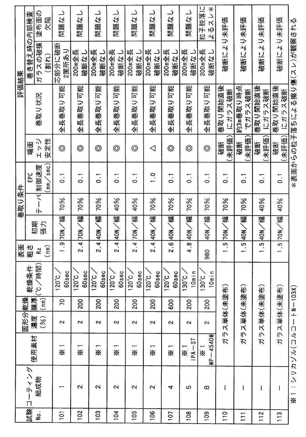
以上の如く、水性シリカゾルを含有する組成物の塗布により表面に微細な凹凸を形成した本発明の薄膜ガラスは(ブロッキング等もなく)ロールに巻き取りが可能であったが、薄膜ガラス単体では、張力、テーパ等をいくら工夫しても、巻き芯部がすぐ破断し巻き取りが出来なかった。
また、試験No.102で巻き取った薄膜ガラスロールについて、23.5℃、湿度55%RHの条件で1週間保管したのち、巻き出し試験を行ったがくっつきもなく再度の巻き出し、巻き取りが可能であった。
1 薄膜ガラス基材供給工程(アンワインダ)
2 コーター
3 ドライヤー
4 巻き取り工程(ワインダ)
2 コーター
3 ドライヤー
4 巻き取り工程(ワインダ)
Claims (9)
- 厚み30~150μmの薄膜ガラスであって、前記薄膜ガラス同士を重ね合わせたとき、接触面に空隙をもたせる様表面処理されたことを特徴とする薄膜ガラス。
- 前記表面処理された薄膜ガラス表面を十点表面粗さ(Rz)で表したとき、Rzが2nm以上であることを特徴とする請求項1に記載の薄膜ガラス。
- 薄膜ガラス表面への前記表面処理が、前記薄膜ガラス表面への、水性シリカゾルを含有する組成物の塗布・乾燥による被膜の形成であることを特徴とする請求項1または2に記載の薄膜ガラス。
- 前記水性シリカゾルを含有する組成物が、無機酸化物微粒子を含有することを特徴とする請求項3に記載の薄膜ガラス。
- 前記無機酸化物微粒子が、珪素酸化物であることを特徴とする請求項4に記載の薄膜ガラス。
- 前記水性シリカゾルを含有する組成物から形成される被膜が、耐熱性かつ透明な被膜であることを特徴とする請求項3~5のいずれか1項に記載の薄膜ガラス。
- 請求項3~6のいずれか1項に記載の薄膜ガラスの製造方法であって、前記薄膜ガラスへの前記水性シリカゾルを含有する組成物の塗布・乾燥がロールツーロール生産ラインの中で行われることを特徴とする薄膜ガラスの製造方法。
- 請求項3~6のいずれか1項に記載の薄膜ガラスを巻き取ったことを特徴とする薄膜ガラスロール。
- 薄膜ガラスをロール状に巻き取る薄膜ガラスの巻き取り方法であって、前記薄膜ガラスが、薄膜ガラス同士を重ね合わせたとき、接触面に空隙をもたせるように表面処理されていることを特徴とする薄膜ガラスの巻き取り方法。
Applications Claiming Priority (2)
| Application Number | Priority Date | Filing Date | Title |
|---|---|---|---|
| JP2010032256A JP5515829B2 (ja) | 2010-02-17 | 2010-02-17 | フレキシブルな薄膜ガラスおよびその製造方法 |
| JP2010-032256 | 2010-02-17 |
Publications (1)
| Publication Number | Publication Date |
|---|---|
| WO2011102271A1 true WO2011102271A1 (ja) | 2011-08-25 |
Family
ID=44482858
Family Applications (1)
| Application Number | Title | Priority Date | Filing Date |
|---|---|---|---|
| PCT/JP2011/052712 Ceased WO2011102271A1 (ja) | 2010-02-17 | 2011-02-09 | フレキシブルな薄膜ガラスとその製造方法及び薄膜ガラスロールとその巻き取り方法 |
Country Status (2)
| Country | Link |
|---|---|
| JP (1) | JP5515829B2 (ja) |
| WO (1) | WO2011102271A1 (ja) |
Cited By (5)
| Publication number | Priority date | Publication date | Assignee | Title |
|---|---|---|---|---|
| WO2015118983A1 (ja) * | 2014-02-06 | 2015-08-13 | 旭硝子株式会社 | 樹脂塗膜付ガラスシートの製造方法 |
| WO2015118985A1 (ja) * | 2014-02-06 | 2015-08-13 | 旭硝子株式会社 | ガラスロール |
| WO2015118984A1 (ja) * | 2014-02-06 | 2015-08-13 | 旭硝子株式会社 | ガラス樹脂複合体 |
| US20160161423A1 (en) * | 2013-08-01 | 2016-06-09 | Schott Ag | Method and device for detecting defects in coils of brittle or fracture-prone material which is at least partially transparent, and use of said method and device |
| WO2017034960A1 (en) * | 2015-08-21 | 2017-03-02 | Corning Incorporated | Systems and methods for bulk processing substrate webs |
Families Citing this family (4)
| Publication number | Priority date | Publication date | Assignee | Title |
|---|---|---|---|---|
| JP6016723B2 (ja) * | 2012-08-07 | 2016-10-26 | 株式会社神戸製鋼所 | ガラスフィルム搬送装置 |
| JP6068072B2 (ja) * | 2012-09-14 | 2017-01-25 | グンゼ株式会社 | ガラスフィルム |
| DE102014207792A1 (de) * | 2014-04-25 | 2015-10-29 | Tesa Se | Dünnglasverbund und Verfahren zum Lagern einer Dünnglasfolie |
| JP2016196343A (ja) * | 2015-04-03 | 2016-11-24 | 株式会社セリアエンジニアリング | 搬送装置 |
Citations (2)
| Publication number | Priority date | Publication date | Assignee | Title |
|---|---|---|---|---|
| JP2006161157A (ja) * | 2004-11-10 | 2006-06-22 | Dainippon Printing Co Ltd | 金属酸化物膜の製造方法 |
| JP2007331996A (ja) * | 2006-06-16 | 2007-12-27 | Asahi Glass Co Ltd | 機能性ガラス体 |
Family Cites Families (1)
| Publication number | Priority date | Publication date | Assignee | Title |
|---|---|---|---|---|
| JP2001180981A (ja) * | 1999-12-24 | 2001-07-03 | Asahi Glass Co Ltd | 防眩性の塗膜を有する外装用硝子部材およびその設置方法 |
-
2010
- 2010-02-17 JP JP2010032256A patent/JP5515829B2/ja not_active Expired - Fee Related
-
2011
- 2011-02-09 WO PCT/JP2011/052712 patent/WO2011102271A1/ja not_active Ceased
Patent Citations (2)
| Publication number | Priority date | Publication date | Assignee | Title |
|---|---|---|---|---|
| JP2006161157A (ja) * | 2004-11-10 | 2006-06-22 | Dainippon Printing Co Ltd | 金属酸化物膜の製造方法 |
| JP2007331996A (ja) * | 2006-06-16 | 2007-12-27 | Asahi Glass Co Ltd | 機能性ガラス体 |
Cited By (6)
| Publication number | Priority date | Publication date | Assignee | Title |
|---|---|---|---|---|
| US20160161423A1 (en) * | 2013-08-01 | 2016-06-09 | Schott Ag | Method and device for detecting defects in coils of brittle or fracture-prone material which is at least partially transparent, and use of said method and device |
| US10222342B2 (en) * | 2013-08-01 | 2019-03-05 | Schott Ag | Method and device for detecting defects in coils of brittle or fracture-prone material which is at least partially transparent, and use of said method and device |
| WO2015118983A1 (ja) * | 2014-02-06 | 2015-08-13 | 旭硝子株式会社 | 樹脂塗膜付ガラスシートの製造方法 |
| WO2015118985A1 (ja) * | 2014-02-06 | 2015-08-13 | 旭硝子株式会社 | ガラスロール |
| WO2015118984A1 (ja) * | 2014-02-06 | 2015-08-13 | 旭硝子株式会社 | ガラス樹脂複合体 |
| WO2017034960A1 (en) * | 2015-08-21 | 2017-03-02 | Corning Incorporated | Systems and methods for bulk processing substrate webs |
Also Published As
| Publication number | Publication date |
|---|---|
| JP5515829B2 (ja) | 2014-06-11 |
| JP2011168423A (ja) | 2011-09-01 |
Similar Documents
| Publication | Publication Date | Title |
|---|---|---|
| JP5515829B2 (ja) | フレキシブルな薄膜ガラスおよびその製造方法 | |
| JP5394094B2 (ja) | 複層フィルム及びその製造方法 | |
| JP7182358B2 (ja) | 低屈折率層含有粘接着シート、低屈折率層含有粘接着シートの製造方法、および光学デバイス | |
| JP6387625B2 (ja) | ガスバリアフィルムの製造方法 | |
| JP6563750B2 (ja) | 塗料およびその製造方法 | |
| WO2010100285A1 (en) | Slot die coating process | |
| KR102169533B1 (ko) | 공극층, 적층체, 공극층의 제조 방법, 광학 부재 및 광학 장치 | |
| CN102682876A (zh) | 透明导电性薄膜及触摸面板 | |
| JP2016060158A (ja) | セラミックシート製造用離型フィルム | |
| KR20180039582A (ko) | 광학 적층체, 광학 적층체의 제조 방법, 광학 부재, 화상 표시 장치 | |
| CN110088177B (zh) | 带有硬涂层的制品 | |
| JP2015160926A (ja) | 水性組成物、ハードコートフィルム、積層フィルム、透明導電性フィルム、およびタッチパネル | |
| JP2019072850A (ja) | セラミックグリーンシート製造用離型フィルム | |
| KR20110066104A (ko) | 복층 필름 및 그 제조 방법 | |
| US20150219801A1 (en) | Manufacturing method for a glass that has an antireflection property and glass that has an antireflection property | |
| JP2018001633A (ja) | 光学積層体の製造方法、および光学積層体中間体 | |
| JP5509571B2 (ja) | 微粒子積層薄膜付き基材、その製造方法及びそれを用いた光学部材 | |
| TWI728282B (zh) | 阻隔膜 | |
| WO2017043496A1 (ja) | 低屈折率層、積層フィルム、低屈折率層の製造方法、積層フィルムの製造方法、光学部材および画像表示装置 | |
| JP2005248173A (ja) | コーティング用塗料、それを用いた光学フィルムの製造方法、光学フィルム、偏光板および画像表示装置 | |
| JP5463633B2 (ja) | 透明ガスバリアフィルム、透明包装材料 | |
| EP1287983B1 (en) | Easy handling thermoplastic film | |
| JP2012116184A (ja) | 積層ポリエステルフィルム、及びそれを用いた透明導電性フィルム | |
| WO2019208483A1 (ja) | 低屈折部材、転写シート、コーティング組成物、及び低屈折部材を用いた積層体 | |
| WO2015118985A1 (ja) | ガラスロール |
Legal Events
| Date | Code | Title | Description |
|---|---|---|---|
| 121 | Ep: the epo has been informed by wipo that ep was designated in this application |
Ref document number: 11744558 Country of ref document: EP Kind code of ref document: A1 |
|
| NENP | Non-entry into the national phase |
Ref country code: DE |
|
| 122 | Ep: pct application non-entry in european phase |
Ref document number: 11744558 Country of ref document: EP Kind code of ref document: A1 |