WO2011102224A1 - エアバッグ - Google Patents
エアバッグ Download PDFInfo
- Publication number
- WO2011102224A1 WO2011102224A1 PCT/JP2011/052161 JP2011052161W WO2011102224A1 WO 2011102224 A1 WO2011102224 A1 WO 2011102224A1 JP 2011052161 W JP2011052161 W JP 2011052161W WO 2011102224 A1 WO2011102224 A1 WO 2011102224A1
- Authority
- WO
- WIPO (PCT)
- Prior art keywords
- diffuser
- inflator
- airbag
- insertion hole
- guide member
- Prior art date
- Legal status (The legal status is an assumption and is not a legal conclusion. Google has not performed a legal analysis and makes no representation as to the accuracy of the status listed.)
- Ceased
Links
Images









Classifications
-
- B—PERFORMING OPERATIONS; TRANSPORTING
- B60—VEHICLES IN GENERAL
- B60R—VEHICLES, VEHICLE FITTINGS, OR VEHICLE PARTS, NOT OTHERWISE PROVIDED FOR
- B60R21/00—Arrangements or fittings on vehicles for protecting or preventing injuries to occupants or pedestrians in case of accidents or other traffic risks
- B60R21/02—Occupant safety arrangements or fittings, e.g. crash pads
- B60R21/16—Inflatable occupant restraints or confinements designed to inflate upon impact or impending impact, e.g. air bags
- B60R21/20—Arrangements for storing inflatable members in their non-use or deflated condition; Arrangement or mounting of air bag modules or components
- B60R21/217—Inflation fluid source retainers, e.g. reaction canisters; Connection of bags, covers, diffusers or inflation fluid sources therewith or together
- B60R21/2171—Inflation fluid source retainers, e.g. reaction canisters; Connection of bags, covers, diffusers or inflation fluid sources therewith or together specially adapted for elongated cylindrical or bottle-like inflators with a symmetry axis perpendicular to the main direction of bag deployment, e.g. extruded reaction canisters
-
- B—PERFORMING OPERATIONS; TRANSPORTING
- B60—VEHICLES IN GENERAL
- B60R—VEHICLES, VEHICLE FITTINGS, OR VEHICLE PARTS, NOT OTHERWISE PROVIDED FOR
- B60R21/00—Arrangements or fittings on vehicles for protecting or preventing injuries to occupants or pedestrians in case of accidents or other traffic risks
- B60R21/02—Occupant safety arrangements or fittings, e.g. crash pads
- B60R21/16—Inflatable occupant restraints or confinements designed to inflate upon impact or impending impact, e.g. air bags
- B60R21/23—Inflatable members
- B60R21/231—Inflatable members characterised by their shape, construction or spatial configuration
- B60R21/2334—Expansion control features
- B60R21/2346—Soft diffusers
-
- B—PERFORMING OPERATIONS; TRANSPORTING
- B60—VEHICLES IN GENERAL
- B60R—VEHICLES, VEHICLE FITTINGS, OR VEHICLE PARTS, NOT OTHERWISE PROVIDED FOR
- B60R21/00—Arrangements or fittings on vehicles for protecting or preventing injuries to occupants or pedestrians in case of accidents or other traffic risks
- B60R21/02—Occupant safety arrangements or fittings, e.g. crash pads
- B60R21/16—Inflatable occupant restraints or confinements designed to inflate upon impact or impending impact, e.g. air bags
- B60R21/20—Arrangements for storing inflatable members in their non-use or deflated condition; Arrangement or mounting of air bag modules or components
- B60R21/205—Arrangements for storing inflatable members in their non-use or deflated condition; Arrangement or mounting of air bag modules or components in dashboards
- B60R21/206—Arrangements for storing inflatable members in their non-use or deflated condition; Arrangement or mounting of air bag modules or components in dashboards in the lower part of dashboards, e.g. for protecting the knees
-
- B—PERFORMING OPERATIONS; TRANSPORTING
- B60—VEHICLES IN GENERAL
- B60R—VEHICLES, VEHICLE FITTINGS, OR VEHICLE PARTS, NOT OTHERWISE PROVIDED FOR
- B60R21/00—Arrangements or fittings on vehicles for protecting or preventing injuries to occupants or pedestrians in case of accidents or other traffic risks
- B60R21/02—Occupant safety arrangements or fittings, e.g. crash pads
- B60R21/16—Inflatable occupant restraints or confinements designed to inflate upon impact or impending impact, e.g. air bags
- B60R21/23—Inflatable members
- B60R21/237—Inflatable members characterised by the way they are folded
Definitions
- the present invention relates to an airbag used as a knee airbag or the like housed under the instrument panel.
- the knee airbag is an occupant restraint device that inflates and deploys near the occupant's knee when an accident occurs in the vehicle. By providing the knee airbag, the occupant's knee can be protected from a collision with an instrument panel or the like.
- the knee airbag is mainly housed in the lower part of the instrument panel, for example, in the lower part of the steering column cover in the driver's seat.
- the knee airbag is attached in a state in which the knee airbag is bundled by folding or winding so that the knee airbag can be attached to a limited storage space.
- the gas is supplied from an inflator (gas generator) and is expanded and deployed to the inside of the vehicle.
- the knee airbag must be inflated and deployed in the space from the lower part of the instrument panel to the knee of the occupant. Since this space is very narrow, the knee airbag cannot be prevented from colliding with the instrument panel unless it is inflated and deployed quickly. Therefore, the knee airbag has been devised such as a folding method that can be instantly deployed and a smoother gas inflow method.
- Patent Literature 1 discloses a knee protection bag-integrated airbag device for a passenger seat that includes an inflator inserted into a substantially cylindrical diffuser (rectifier). According to Patent Document 1, the first to third rectifying openings having different opening areas are formed in the diffuser. By using this, the knee protection bag precedes the head / chest protection bag. It is said that it can be deployed.
- the tubular diffuser is long and overlaps the insertion hole of the inflator. Therefore, a hole is made in the diffuser at a position overlapping with the insertion hole, and the inflator inserted from the outside to the inside through the insertion hole is guided and inserted into the diffuser as it is.
- both ends of the long diffuser are blocked by the folding when the airbag is accommodated, resulting in so-called choking in which gas cannot be smoothly ejected from both ends of the tubular diffuser during inflation and deployment.
- the diffuser does not overlap the insertion hole and is positioned slightly away from the insertion hole.
- the present invention provides an airbag that can be inserted into a diffuser without departing from the inflator, even though the tubular portion of the diffuser inside the airbag is short and away from the inflator insertion hole.
- the purpose is to do.
- a representative configuration of the present invention is an airbag that accommodates a cylinder-type inflator therein, and an insertion hole for inserting the inflator from the outside of the airbag into the interior, It has a diffuser that forms a semi-closed space by having an opening, and has a guide member that introduces the inflator into the semi-closed space when the inflator is inserted.
- the guide member may be connected to the edge of the opening so that the inflator can be guided almost continuously from the insertion hole to the opening.
- the guide member may be provided so as to substantially overlap the insertion hole so that the inflator can be guided substantially continuously from the insertion hole to the opening.
- another typical configuration of the present invention is an air bag that accommodates a cylinder-type inflator, and is positioned between first and second sewing lines provided on a base fabric.
- a diffuser that has a tubular portion sewn and a fabric on the side close to the base fabric of the tubular portion is further sewn to the base fabric in the second sewing line, and the diffuser is continuous from the inner surface of the diffuser It has the guide member sewn on the base fabric by the 1st sewing line which covers an insertion hole with a field.
- the tip of the inflator inserted from the insertion hole hits the guide member of the diffuser.
- the surface of the guide member that the inflator collides with is continuous from the inner surface of the diffuser. Therefore, even if the tubular portion of the diffuser is separated from the insertion hole to prevent choking, the inflator can be guided by the guide member and inserted into the diffuser without deviating only by pushing the inflator.
- the above diffuser has a multiple tubular shape in which a plurality of cloths are folded and overlapped, and the innermost cloth of the multiple tubulars may have a guide member.
- the tubular portion of the diffuser may have a rectangular cross section. This is because when the tubular portion has a rectangular cross section, the rectifying action of the tubular portion substantially functioning as a diffuser is maximized.
- the present invention it is possible to provide an airbag that can be inserted into a diffuser without departing from the inflator, even though the tubular portion of the diffuser inside the airbag is short and away from the inflator insertion hole.
- FIG. 1 It is a figure which illustrates the storage position in the vehicle of the knee airbag concerning embodiment of this invention. It is an exploded view of the knee airbag of FIG. It is a figure which illustrates the expansion
- FIG. 1 It is a figure which illustrates the storage position in the vehicle of the knee airbag concerning embodiment of this invention. It is an exploded view of the knee airbag of FIG. It is a figure which illustrates the expansion
- FIG. 4 is a view in which a part of the cushion part in FIG. It is a figure which illustrates the process of folding the cushion part of FIG. It is a figure which illustrates the process of folding the cushion part of FIG. It is a figure which illustrates the process of folding the cushion part of FIG. 9, and is a figure which illustrates the state which turned the cushion part upside down so that the roll part formed in FIG. It is a figure which illustrates the process of folding the cushion part of FIG. It is a figure which illustrates the process of folding the cushion part of FIG. It is a figure which illustrates the process of folding the cushion part of FIG. It is a figure which illustrates the process of folding the cushion part of FIG. It is a figure which illustrates the behavior at the time of expansion
- FIG. 1 is a diagram illustrating a storage position in a vehicle of a knee airbag according to an embodiment of the present invention.
- the knee airbag 100 is stored below the instrument panel 102.
- the knee airbag 100 of the present embodiment is for a driver's seat and is stored below the steering column cover 104.
- the knee airbag 100 is inflated and deployed inside the vehicle when an impact such as a collision accident occurs. Although illustration is omitted, the knee airbag 100 can also be used as a passenger seat airbag.
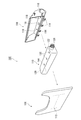
- FIG. 2 is an exploded view of the knee airbag of FIG. As illustrated in FIG. 2, the knee airbag 100 includes a cushion portion 110 that is folded in a space between the knee airbag cover 106 and the housing 108.
- the knee airbag cover 106 is exposed as an interior member in the vehicle.
- a tear line 112 is engraved on the inner side (cushion part 110 side) of the knee airbag cover 106 that is ruptured by the expansion and deployment of the cushion part 110.
- the housing 108 is a box material that serves as an exterior for the cushion portion 110.
- the housing 108 includes the cushion part 110 and is attached to the vehicle.
- the housing 108 is provided with a plurality of hook portions 114 for attaching the knee airbag cover 106.
- the housing 108 is preferably made of a material having high rigidity to support the cushion portion 110 that expands and deploys, and the housing 108 of the present embodiment is made of metal.
- the housing 108 is provided with an inflator attachment port 116 and a bolt hole 118.
- One end (connector 126 side) of the inflator 122 to be inserted into the cushion portion 110 is attached to the inflator attachment port 116.
- a stud bolt 130 and a welding bolt 144 provided in the inflator 122 are passed through the bolt hole 118 and fixed.
- the cushion part 110 is a member that inflates and deploys to protect the occupant.
- the cushion part 110 is attached in the housing 108 in a state where the cushion part 110 is gathered together by folding and winding.
- the cushion part 110 is packaged with a flap 120 for maintaining the folded state.
- the flap 120 is a thin cloth material and can be easily broken in response to the expansion and expansion of the cushion portion 110.
- An inflator 122 serving as a supply source of gas for inflation and deployment is inserted into the cushion part 110.
- FIG. 3 is a diagram illustrating an expanded state of the cushion part 110 of FIG. As illustrated in FIG. 3, the cushion part 110 is formed by sewing a base fabric constituting the surface thereof on the front and back sides.
- the cushion part 110 is provided with an insertion hole 124 for inserting the inflator 122 inserted into the deflector 132 from the outside to the inside.
- one end (the connector 126 side) of the inflator 122 is exposed from the insertion hole 124 (see FIG. 2).
- output signal wiring (not shown) is connected to the connector 126 through the inflator attachment port 116.
- the cushion part 110 is provided with a bolt hole 128, and the stud bolt 130 and the welding bolt 144 of the inserted inflator 122 can be exposed to the outside.
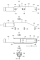
- FIG. 4 is a diagram illustrating the deflector 132 that houses the inflator 122 of FIG. 4A is an enlarged view of the deflector 132 and the inflator 122 of FIG. 3
- FIG. 4B is an arrow A view of the deflector 132 and the inflator 122 of FIG. 4A
- FIG. FIG. 4B is an arrow B view of the deflector 132 and the inflator 122 of FIG. 4B
- FIG. 4D is an arrow C view of FIG.
- the inflator 122 is a cylinder type.
- the inflator 122 has an ignition device and a gas generating agent inside, and when an output signal is received from a wiring (not shown) to be connected, the ignition device is activated, and the surrounding gas generating agent is burned instantaneously and air A gas for inflating and expanding the bag is generated.
- the generated gas is supplied to the cushion part 110 from a gas outlet 134 provided on the surface of the inflator 122.
- the inflator 122 has a stud bolt 130. As shown in FIG. The stud bolt 130 passes through the bolt hole 136 of the deflector 132, the bolt hole 128 of the cushion portion 110, and the bolt hole 118 of the housing 108 and fastens them.
- the deflector 132 is a member that rectifies the gas ejected from the inflator 122.
- the deflector 132 accommodates at least the gas ejection port 134 with one end of the inflator 122 exposed.
- the end portion 138 on the welding bolt 144 side of the deflector 132 has a tapered shape. Further, as illustrated in FIG. 4C, the end portion 138 is subjected to a bending process for rounding the corner 140 at the tip. Thereby, the insertion to the cushion part 110 can be performed smoothly, without being caught.
- the deflector 132 fixes the inflator 122 so that the gas outlet 134 of the inflator 122 is located at the approximate center in the longitudinal direction.
- the deflector 132 has a rectifying portion 142 for rectifying the gas without the inflator 122. By providing the rectifying portion 142, the gas is rectified in the longitudinal direction of the deflector 132 (in the cushion portion 110, its width direction).
- the deflector 132 is made of metal and has not only a function of rectifying gas but also a function of protecting the cushion part 110 from heat generated by the gas.
- the deflector 132 is provided with a bolt hole 136 through which the stud bolt 130 of the inflator 122 is passed.
- the deflector 132 is fixed to the housing 108 together with the inflator 122 and the cushion portion 110 by the stud bolt 130 (see FIG. 2).
- the deflector 132 has a welding bolt 144 (see FIG. 4B), and is also fixed to the housing 108 by the welding bolt.
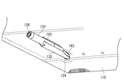
- FIG. 5 is a diagram illustrating a state in which the inflator 122 of FIG. 4 is inserted into the cushion portion 110 of FIG. 3 from the insertion hole 124 together with the deflector 132.
- a connector 126 is provided at one end of the inflator 122, and wiring for sending an external signal to an internal ignition device is connected. Therefore, the inflator 122 is positioned with respect to the deflector 132 by a stud bolt 130 or the like that the inflator 122 itself has, and one end of the inflator 122 is exposed from the deflector 132 and the cushion part 110, so that wiring can be easily connected.
- the deflector 132 is provided with the rectifying portion 142 that rectifies the gas without the inflator 122.
- the claw 150 is provided on the deflector 132 so that the inflator 122 is accommodated with one end exposed, and the inflator 122 is straight with the deflector 132 despite the presence of the rectifying portion 142 where the inflator 122 does not exist. It can be fixed to a proper posture. Therefore, when the deflector 132 is inserted into the cushion part 110, the inflator 122 can be prevented from coming off from the deflector 132 more reliably.
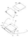
- (Diffuser) 6 is a view of the cushion portion 110 of FIG. In other words, the base fabric on the opposite side is not shown.
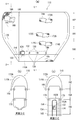
- a diffuser 152 into which the inflator 122 and the deflector 132 inserted from the insertion hole 124 are inserted is provided on the back side of the base fabric 110A provided with the insertion hole 124 in FIG.
- the insertion hole 124 and the deflector 132 are not visible, and thus are indicated by broken lines.
- the diffuser 152 rectifies the gas supplied from the inflator 122 in the left-right direction in FIG. 6 by inserting the inflator 122 together with the deflector 132.
- the base cloth 110A is provided with a first sewing line 154 and a second sewing line 156, and the insertion hole 124 is located between them.
- FIG. 7 is an exploded view of the diffuser of FIG. In FIG. 7, the inflator 122 and the deflector 132 are not shown.
- the diffuser 152 is formed by folding back two sheets of diffuser fabrics 152 ⁇ / b> A and 152 ⁇ / b> B. The portions of the diffuser fabrics 152A and 152B that are folded and overlapped are sewn to the base fabric 110A by the first sewing line 154.
- the diffuser 152 has a double tubular shape.
- the diffuser 152 has a double tubular shape, but the number of cloths may be increased or decreased, and may be a single tube or a triple tube or more.
- the sewing procedure is as follows. First, the overlapped diffuser cloths 152A and 152B are sewn on the inner side of the airbag body along the second sewing line 156. Thereafter, as shown in FIG. 7, the diffuser cloths 152 ⁇ / b> A and 152 ⁇ / b> B are folded back and sewed along the first sewing line 154. The diffuser 152 becomes tubular only when the first sewing line 154 is sewn.
- the cloth on the side close to the base cloth 110A is further sewn to the base cloth 110A by the second sewing line 156.
- the double tubular innermost cloth 152 ⁇ / b> B of the diffuser 152 has a guide member 160.
- the guide member 160 covers the insertion hole 124 with a surface continuous from the inner surface of the diffuser 152 (the inner surface of the folded cloth 152B).
- the guide member 160 is sewn to the base cloth 110 ⁇ / b> A along the first sewing line 154.
- FIG. 8 is a view of the cushion part 110 of FIG. 5 as viewed from the inside.
- the tip of the inflator 122 (actually the deflector 132 that accommodates the inflator 122) inserted from the insertion hole 124 hits the guide member 160 of the diffuser 152.
- the surface of the guide member 160 that collides is continuous from the inner surface of the diffuser 152 (the inner surface of the folded cloth 152B). Therefore, in order to prevent choking, the inflator 122 is guided only by pushing in the inflator 122 as shown in FIG. 8 even though the tubular portion 153 of the diffuser 152 is separated from the insertion hole 124 (see FIGS. 6 and 7). It is guided by the member 160 and can be inserted into the diffuser 152 as shown in FIG. 6 without departing.
- the guide member 160 of the diffuser 152 is a single cloth and is not tubular, and therefore does not substantially function as the diffuser 152. Therefore, the guide member 160 does not cause choking. However, the guide member 160 is sewn to the base fabric 110A by the first sewing line 154. Therefore, even if the interpolated inflator 122 and the deflector 132 collide with each other, they can be guided to the inner surface of the diffuser 152 without causing positional displacement.
- the diffuser 152 has been shortened due to a problem of choking.
- the diffuser 152 does not overlap the insertion hole 124 and is positioned slightly away from the insertion hole 124, so that the tip of the inserted inflator 122 must be moved to the end of the tubular diffuser 152 and inserted. Occurred.
- the inflator 122 may accidentally deviate from the pipe of the diffuser 152, but this embodiment solves this problem.
- the inflator 122 when the diffuser 152 is formed in multiple tubes in order to increase the strength of the diffuser 152, the inflator 122 needs to be inserted into the innermost tube, that is, the diffuser cloth 152B. Therefore, the guide member 160 is provided on the innermost diffuser cloth 152B. Thereby, not only the deviation of the inflator 122 to the outside of the diffuser 152 but also the inflator 122 can be prevented from entering the gap between the multiple tubes constituting the diffuser 152 (the gap between the diffuser cloths 152A and 152B). .
- the tubular portion 153 of the diffuser 152 has a rectangular cross section. This is because when the tubular portion 153 has a rectangular cross section, the rectifying action of the tubular portion 153 that substantially functions as a diffuser is maximized.
- This embodiment forms a semi-closed space by having an insertion hole for inserting the inflator from the outside to the inside of the airbag and the opening substantially in the airbag accommodating the cylinder type inflator. And a guide member for introducing the inflator into the semi-closed space when the inflator is inserted.
- the guide member may be connected to the edge of the opening so that the inflator can be guided almost continuously from the insertion hole to the opening.
- the guide member may be provided so as to substantially overlap the insertion hole so that the inflator can be guided substantially continuously from the insertion hole to the opening.
- FIG. 9 is a view in which the cushion portion 110 of FIG. 3 is partially cut away to expose the inner surface of each chamber.
- FIG. 9A is a front view of the cushion part 110.
- 9B is a cross-sectional view taken along the line DD of FIG. 9A, and is a cross-sectional view of the cushion portion 110 taken along the second fold line 188.
- FIG. 9C is a cross-sectional view taken along the line EE of FIG.
- the cushion portion 110 includes first to third three chambers 162, 164, 166.
- the first chamber 162 and the second chamber 164 are substantially rectangular adjacent to each other at a boundary (third sewing line 168) in the longitudinal direction (left-right direction in FIG. 9) having substantially the same dimensions.
- the third chamber 166 has a substantially trapezoidal shape having an upper base (fourth sewing line 170) having a size substantially equal to the longitudinal boundary and a lower bottom (peripheral sewing line 154) shorter than the fourth sewing line 170. is there.
- the third chamber 166 is adjacent to the second chamber 164 at the fourth sewing line 170.
- the third chamber 166 accommodates the cylinder-type inflator 122 in the vicinity of the first sewing line 154 along the first sewing line 154.
- the inner surface of one base fabric on the back side of the drawing among the two base fabrics forming the first chamber 162 is a coated fabric 172A coated with silicon.
- the outer surface of the base fabric abuts on the occupant's knee and restrains the occupant from moving forward.
- the inner surface of the other base fabric on the front side of the drawing is a non-coated fabric 174A that is not coated with silicon.
- the first chamber 162 may be composed of any number of base fabrics, but the coated fabric 172A and the non-coated fabric 174A are the two innermost sheets forming the first chamber 162. It should be noted that different cloths may be used as the inner surface of the first chamber 162, and the material may be exchanged between the near side and the far side.
- the first chamber 162 Since the first chamber 162 is farthest from the inflator 122, it is a portion to which gas is supplied most late. In the first chamber 162, when the cushion part 110 is deployed, the folded or wound part remains until the end. Since the cushion part 110 is thus delayed in deployment, the cushion part 110 is pulled by another portion that is deployed in advance, causing twisting and the like, and friction between the inner surfaces is likely to occur and damage is likely to occur.
- the portion where friction is likely to occur is the coated fabric 172A and the non-coated fabric 174A. This is because even when these different types of fabrics generate friction, damage can be prevented more effectively than when the same types of fabrics generate friction.
- the inner surface of the base fabric of the second chamber is coated fabric 172B and 172C on both the back side and the near side in the drawing.
- the inner surface of the base fabric of the third chamber 166 is the non-coated fabric 174B, 174C on both the back side and the near side in the drawing.
- the outer surface (not shown) of the base fabric of the third chamber 166 is a coated fabric.
- FIG. 10 to 15 are diagrams illustrating a process of folding the cushion part 110 of FIG. 9.
- the cushion part 110 is folded or wound a plurality of times from the first chamber 162 toward the third chamber 166.
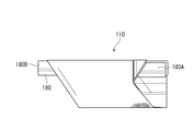
- a roll unit 180 is formed as illustrated in FIG.
- FIG. 12 is a view illustrating a state in which the cushion portion 110 is turned over so that the roll portion 180 formed in FIG. 11 faces the back side of the drawing.
- FIG. 14 is a diagram illustrating a state in which the tip of one end 180 ⁇ / b> A of the roll unit 180 that has been subjected to the first folding is further folded back toward both ends of the roll unit 180. This is hereinafter referred to as second folding. These first folding and second folding are performed on both ends 180A and 180B of the roll unit 180, as illustrated in FIG. This completes the folding.
- FIG. 16 is a diagram exemplifying the behavior at the time of unfolding of the cushion part 110 after the folding of FIG. 15 is completed.
- FIG. 16A corresponds to the arrow F diagram of FIG. 15, and development is performed in the order of FIG. 16A, FIG. 16B, and FIG.
- the folded cushion part 110 When viewed from the occupant seated in the driver's seat in FIG. 1, the folded cushion part 110 is in such a posture, and although it is not actually visible to the occupant, a substantially “ ⁇ ” shape is directed toward the occupant.
- the behavior at the time of unfolding does not reverse correctly from the end to the beginning of the folding process. That is, as illustrated in FIG. 16A, the behavior of expanding the first folding and the second folding performed at the end of the folding process in the left-right direction (arrow 184 in FIG. 16B). ), The roll portion formed at the initial stage of folding (arrow 182) is performed.
- the cushion part 110 is twisted.
- damage 190 occurs on the track of the second folding line 188 among the first folding line 186 and the second folding line 188 (only the left side is illustrated) on the inner surface of the cushion portion 110.
- the first chamber 162 since the first chamber 162 is located on the innermost side of the roll portion 180, the first chamber 162 does not expand to the end, and friction is easily generated on the inner surface due to the influence of twisting. Therefore, the damage 190 often occurs on the inner surface of the first chamber 162 and on the trajectory of the second fold line 188.
- the inner surface of the first chamber 162 is formed of different kinds of coated cloth 172A and non-coated cloth 174A, so that even if friction occurs, damage is unlikely to occur.
- FIG. 1 In a bag-like airbag (for example, the knee airbag 100) including one or more chambers, the airbag is folded or wound, and the chamber (for example, the chamber 162) includes the airbag.
- the airbag is folded or wound, the cloth is provided at a place where the release is delayed compared to other parts (for example, in the vicinity of the damage 190).
- the above cloth may be provided at the innermost side of folding or winding at a position away from the inflator accommodated in the airbag.
- the above cloth may be a non-coated cloth (for example, a non-coated cloth 174A) that is not coated with silicon.
- FIG. 17 is a view illustrating a cushion part 210 having a diffuser 252 obtained by modifying the diffuser 152 of FIG. Only differences from FIG. 6 will be described below. Whereas the diffuser 152 of FIG. 6 has a tubular portion 153 having a rectangular cross section, the tubular portion 253 of the diffuser 252 of FIG. 17 has a trapezoidal cross section.
- the diffuser 252 is formed by stacking substantially congruent and symmetrical trapezoidal cloths in which a hexagonal cloth is folded at any diagonal line and the folded diagonal line is the upper base 254. A portion corresponding to the lower base 256 of the trapezoid is sewn to the base fabric 210A by the first sewing line 154.
- the inflator 122 is inserted together with the deflector 132 in the vicinity of the lower bottom 256 of the tubular portion 253.
- folding is performed on both outer sides of a portion corresponding to the lower bottom 256 of the diffuser 252 by a fold line (first folding line 186) substantially orthogonal to the longitudinal direction of the diffuser 252.
- the cushion portion 210 does not cause choking and is rapidly deployed. This is because the lower bottom 256 having a short length is not bitten by the first folding line 186 and the inflator 122 is inserted in the vicinity of the lower bottom 256, so that the gas outlet is not blocked.
- FIG. 18 is a view illustrating a cushion part 210 having a diffuser 262 obtained by further modifying the diffuser 252 of FIG. Only differences from FIG. 17 will be described below.
- the upper bottom 264 of the diffuser 262 in FIG. 18 is longer than the upper bottom 254 in FIG. 17, and is a tubular portion 263 that reaches the first folding line 186 that is the first folding fold.
- the first fold line 186 is located on the inner side from both ends of the portion corresponding to the upper base 264 of the diffuser.
- the upper bottom 264 portion of the diffuser 262 is bitten in the first turn.
- the vicinity of the lower bottom 256 where the inflator 122 and the deflector 132 exist is not bitten by the first folding line 186, choking does not occur.
- the rapid deployment can be maintained.
- the knee airbag in which the cylinder-type inflator 122 is accommodated in the internal diffuser 252, the knee airbag is folded or wound in a bellows shape or a roll shape to roll parts (for example, a roll part 180) is formed, both ends of the roll part are folded back to the center (for example, the first fold), and the outlet of the diffuser is not caught by the fold line (for example, the first fold line 186). To do. As a result, no choking occurs.
- tubular portions 253 and 263 are used.
- the tubular portions 253 and 263 may be used instead of a tubular bag, and a diffuser for guiding gas by providing a vent hole 270.
- the present invention can be used for an airbag used as a knee airbag or the like stored below the instrument panel.
Landscapes
- Engineering & Computer Science (AREA)
- Mechanical Engineering (AREA)
- Air Bags (AREA)
Abstract
Description
102 …インストルメントパネル
104 …ステアリングコラムカバー
106 …ニーエアバッグカバー
108 …ハウジング
110、210 …クッション部
110A …基布
112 …テアライン
114 …フック部
116 …インフレータ取付口
118 …ボルト穴
120 …フラップ
122 …インフレータ
124 …挿入孔
126 …コネクタ
128 …ボルト穴
130 …スタッドボルト
132 …ディフレクタ
134 …ガス噴出口
136 …ボルト孔
138 …端部
140 …角
142 …整流部分
144 …溶着ボルト
152、252、262 …ディフューザ
152A、152B …ディフューザ用布
153、253、263 …管状部分
154 …第1の縫製ライン
156 …第2の縫製ライン
160 …ガイド部材
162 …第1チャンバ
164 …第2チャンバ
166 …第3チャンバ
168 …第3の縫製ライン
170 …第4の縫製ライン
171 …外周縫製ライン
172A …コート布
174A …ノンコート布
180 …ロール部
186 …第1折り返し線
188 …第2折り返し線
190 …損傷
254、264 …上底
256 …下底
図1は、本発明の実施形態にかかるニーエアバッグの車両における収納位置を例示する図である。ニーエアバッグ100は、インストルメントパネル102下方に収納される。本実施形態のニーエアバッグ100は運転席用であって、ステアリングコラムカバー104の下方に収納されている。ニーエアバッグ100は、衝突事故等の衝撃発生時に、車内側に膨張展開する。図示は省略するが、ニーエアバッグ100は助手席用のエアバッグとしても利用可能である。
図6は図3のクッション部110を裏返して内部から見た図である。すなわち反対側の基布は図示省略している。図3の挿入孔124が設けられた基布110Aの裏側には、挿入孔124から挿入されたインフレータ122・ディフレクタ132が内挿されるディフューザ152が設けられている。図6では、挿入孔124およびディフレクタ132(内部にインフレータ122を収容)は、見えていないため、破線で示している。ディフューザ152は、インフレータ122がディフレクタ132とともに内挿されることによって、インフレータ122から供給されるガスを図6の左右方向に整流する。
ディフューザ152の二重の管状の最も内側の布152Bは、ガイド部材160を有する。ガイド部材160は、ディフューザ152の内面(折り返された布152Bの内面)から連続する面で挿入孔124を覆っている。ガイド部材160は、第1の縫製ライン154で基布110Aに縫製されている。
本実施形態は、シリンダ型のインフレータを内部に収容するエアバッグにおいて、インフレータをエアバッグ外部から内部へ挿入するための挿入孔と、実質的に、開口部を有することで、半閉鎖空間を形成するディフューザを有し、インフレータ挿入時にインフレータを半閉鎖空間に導入するガイド部材を有することを特徴とする。
図9は図3のクッション部110を一部切り欠き、各チャンバの内面を露出させた図である。図9(a)はクッション部110の正面図である。図9(b)は図9(a)のD-D断面図であり、クッション部110を第2折り返し線188で切断した断面図である。図9(c)は図9(a)のE-E断面図であり、クッション部110を中央で切断した断面図である。図9に例示するように、クッション部110は、第1ないし第3の3つのチャンバ162、164、166を備える。第1チャンバ162および第2チャンバ164は、実質的に等しい寸法の長手方向(図9の左右方向)の境界(第3の縫製ライン168)にて互いに隣接する略長方形である。
図10ないし図15は、図9のクッション部110を折り畳む工程を例示する図である。図10に例示するように、まずクッション部110は、第1チャンバ162から第3チャンバ166に向かって複数回折り畳まれまたは巻回される。その結果、図11に例示するように、ロール部180が形成される。図12は図11で形成されたロール部180が図面奥側に向くよう、クッション部110を裏返した状態を例示する図である。
以下、クッション部110の内面の材質について、本実施形態の思想をまとめる。本実施形態によれば、1つ以上のチャンバを含む袋態のエアバッグ(例えばニーエアバッグ100)において、当該エアバッグは折り畳まれまたは巻回され、チャンバ(例えばチャンバ162)内には、当該エアバッグの折り畳みまたは巻回が解除されるときに解除が他の部分と比較して遅延する箇所(例えば損傷190の近辺)に、布が設けられていることを特徴とする。
図17は図6のディフューザ152を変形したディフューザ252を有するクッション部210を例示する図である。図6との相違点のみ、以下、説明する。図6のディフューザ152が矩形の断面を有する管状部分153を有していたのに対し、図17のディフューザ252の管状部分253は、台形の断面を有する。
以下、ディフューザの変形例について、本実施形態の思想をまとめる。本実施形態によれば、シリンダ型のインフレータ122を内部のディフューザ252に収容するニーエアバッグにおいて、当該ニーエアバッグには、蛇腹状またはロール状に折り畳まれまたは巻回されることによってロール部(例えばロール部180)が形成され、ロール部の両端が中央に折り返され(例えば第1折り返し)、ディフューザの出口は、その折り返し線(例えば第1折り返し線186)に噛み込まれないことを特徴とする。これにより、チョーキングが生じない。
Claims (6)
- シリンダ型のインフレータを内部に収容するエアバッグにおいて、
前記インフレータを該エアバッグ外部から内部へ挿入するための挿入孔と、
実質的に、開口部を有することで、半閉鎖空間を形成するディフューザを有し、
該インフレータ挿入時に該インフレータを該半閉鎖空間に導入するガイド部材を有することを特徴とするエアバッグ。 - 前記ガイド部材は前記インフレータを前記挿入孔から前記開口部に概ね連続的にガイド可能に、該開口部の縁部に連結していることを特徴とする請求項1に記載のエアバッグ。
- 前記ガイド部材は、前記インフレータを前記挿入孔から前記開口部に概ね連続的にガイド可能に、前記挿入孔に概ね重なるように設けられていることを特徴とする請求項1または2に記載のエアバッグ。
- シリンダ型のインフレータを内部に収容するエアバッグにおいて、
基布に設けられた第1および第2の縫製ラインの間に位置する、前記インフレータを外部から内部へ挿入するための挿入孔と、
前記挿入孔から挿入されたインフレータが内挿されるディフューザであって、布を折り返して重ねられた部分が第1の縫製ラインで前記基布に縫製された管状部分を有し、該管状部分のうち該基布に近接する側の布が第2の縫製ラインでさらに該基布に縫製されたディフューザと、
を備え、
前記ディフューザは、該ディフューザの内面から連続する面で前記挿入孔を覆う、第1の縫製ラインで前記基布に縫製されたガイド部材を有することを特徴とするエアバッグ。 - 前記ディフューザは、複数枚の布を折り返して重ねられた多重の管状であり、該多重の管状の最も内側の布が、前記ガイド部材を有することを特徴とする請求項4に記載のエアバッグ。
- 前記ディフューザの管状部分は、矩形の断面を有することを特徴とする請求項4または5に記載のエアバッグ。
Priority Applications (2)
| Application Number | Priority Date | Filing Date | Title |
|---|---|---|---|
| JP2012500549A JP5688071B2 (ja) | 2010-02-17 | 2011-02-02 | エアバッグ |
| US13/579,803 US8651513B2 (en) | 2010-02-17 | 2011-02-02 | Airbag |
Applications Claiming Priority (2)
| Application Number | Priority Date | Filing Date | Title |
|---|---|---|---|
| JP2010031883 | 2010-02-17 | ||
| JP2010-031883 | 2010-02-17 |
Publications (1)
| Publication Number | Publication Date |
|---|---|
| WO2011102224A1 true WO2011102224A1 (ja) | 2011-08-25 |
Family
ID=44482817
Family Applications (1)
| Application Number | Title | Priority Date | Filing Date |
|---|---|---|---|
| PCT/JP2011/052161 Ceased WO2011102224A1 (ja) | 2010-02-17 | 2011-02-02 | エアバッグ |
Country Status (3)
| Country | Link |
|---|---|
| US (1) | US8651513B2 (ja) |
| JP (1) | JP5688071B2 (ja) |
| WO (1) | WO2011102224A1 (ja) |
Cited By (3)
| Publication number | Priority date | Publication date | Assignee | Title |
|---|---|---|---|---|
| JP2019111949A (ja) * | 2017-12-25 | 2019-07-11 | Joyson Safety Systems Japan株式会社 | ニーエアバッグ及びニーエアバッグ装置 |
| JP2021004026A (ja) * | 2019-06-26 | 2021-01-14 | 豊田合成株式会社 | 膝保護用エアバッグ装置 |
| US20230347845A1 (en) * | 2020-06-02 | 2023-11-02 | Yuto Kobayashi | Vehicle airbag device and manufacturing method therefor |
Families Citing this family (4)
| Publication number | Priority date | Publication date | Assignee | Title |
|---|---|---|---|---|
| US8998248B2 (en) * | 2013-03-15 | 2015-04-07 | Autoliv Asp, Inc. | Mounting arrangements for airbags |
| KR102027924B1 (ko) * | 2013-04-16 | 2019-10-02 | 현대모비스 주식회사 | 차량의 커튼 에어백 |
| DE102017108493B4 (de) * | 2017-04-21 | 2019-05-09 | Autoliv Development Ab | Kniegassackmodul und Verfahren zum Packen eines Kniegassackes in ein Gehäuse |
| US11214219B2 (en) * | 2019-03-27 | 2022-01-04 | Toyoda Gosei Co., Ltd. | Airbag device |
Citations (4)
| Publication number | Priority date | Publication date | Assignee | Title |
|---|---|---|---|---|
| JP2003034214A (ja) * | 2001-07-03 | 2003-02-04 | Delphi Automotive Systems Sunwoo Corp | 車両用サイドエアバッグ及びそのフォールディング方法 |
| JP2006321334A (ja) * | 2005-05-18 | 2006-11-30 | Toyoda Gosei Co Ltd | 膝保護用エアバッグ装置 |
| JP2007203937A (ja) * | 2006-02-03 | 2007-08-16 | Toyoda Gosei Co Ltd | 膝保護用エアバッグ装置 |
| JP2009196540A (ja) * | 2008-02-22 | 2009-09-03 | Takata Corp | 側突用エアバッグ装置 |
Family Cites Families (10)
| Publication number | Priority date | Publication date | Assignee | Title |
|---|---|---|---|---|
| KR100494985B1 (ko) | 2001-11-12 | 2005-06-13 | 델파이코리아 주식회사 | 차량용 사이드에어백 |
| KR100420173B1 (ko) | 2001-07-03 | 2004-03-02 | 델파이 오토모티브 시스템스 성우 주식회사 | 차량용 사이드 에어백 및 그 폴딩방법 |
| JP4211479B2 (ja) | 2003-05-09 | 2009-01-21 | タカタ株式会社 | 乗員脚部保護装置 |
| JP4345645B2 (ja) * | 2004-11-09 | 2009-10-14 | 豊田合成株式会社 | 膝保護用エアバッグ装置 |
| US7604250B2 (en) | 2005-05-18 | 2009-10-20 | Toyoda Gosei Co., Ltd. | Airbag device |
| JP5219060B2 (ja) * | 2005-11-02 | 2013-06-26 | タカタ株式会社 | エアバッグ装置 |
| KR101366972B1 (ko) * | 2006-10-11 | 2014-03-14 | 키 세이프티 시스템즈 인코포레이티드 | 사이드 에어백 모듈 |
| JP5187818B2 (ja) * | 2007-10-22 | 2013-04-24 | 芦森工業株式会社 | 膝保護用エアバッグ装置 |
| US8500157B2 (en) * | 2009-04-27 | 2013-08-06 | Autoliv Asp, Inc. | Knee airbag assemblies and related methods |
| US8408582B2 (en) * | 2010-06-23 | 2013-04-02 | Autoliv Asp, Inc. | Inflatable airbag assemblies with heat shields |
-
2011
- 2011-02-02 US US13/579,803 patent/US8651513B2/en active Active
- 2011-02-02 JP JP2012500549A patent/JP5688071B2/ja active Active
- 2011-02-02 WO PCT/JP2011/052161 patent/WO2011102224A1/ja not_active Ceased
Patent Citations (4)
| Publication number | Priority date | Publication date | Assignee | Title |
|---|---|---|---|---|
| JP2003034214A (ja) * | 2001-07-03 | 2003-02-04 | Delphi Automotive Systems Sunwoo Corp | 車両用サイドエアバッグ及びそのフォールディング方法 |
| JP2006321334A (ja) * | 2005-05-18 | 2006-11-30 | Toyoda Gosei Co Ltd | 膝保護用エアバッグ装置 |
| JP2007203937A (ja) * | 2006-02-03 | 2007-08-16 | Toyoda Gosei Co Ltd | 膝保護用エアバッグ装置 |
| JP2009196540A (ja) * | 2008-02-22 | 2009-09-03 | Takata Corp | 側突用エアバッグ装置 |
Cited By (6)
| Publication number | Priority date | Publication date | Assignee | Title |
|---|---|---|---|---|
| JP2019111949A (ja) * | 2017-12-25 | 2019-07-11 | Joyson Safety Systems Japan株式会社 | ニーエアバッグ及びニーエアバッグ装置 |
| JP6995611B2 (ja) | 2017-12-25 | 2022-01-14 | Joyson Safety Systems Japan株式会社 | ニーエアバッグ及びニーエアバッグ装置 |
| JP2021004026A (ja) * | 2019-06-26 | 2021-01-14 | 豊田合成株式会社 | 膝保護用エアバッグ装置 |
| JP7215452B2 (ja) | 2019-06-26 | 2023-01-31 | 豊田合成株式会社 | 膝保護用エアバッグ装置 |
| US20230347845A1 (en) * | 2020-06-02 | 2023-11-02 | Yuto Kobayashi | Vehicle airbag device and manufacturing method therefor |
| US12005851B2 (en) * | 2020-06-02 | 2024-06-11 | Autoliv Development Ab | Vehicle airbag device and manufacturing method therefor |
Also Published As
| Publication number | Publication date |
|---|---|
| US20120313358A1 (en) | 2012-12-13 |
| US8651513B2 (en) | 2014-02-18 |
| JP5688071B2 (ja) | 2015-03-25 |
| JPWO2011102224A1 (ja) | 2013-06-17 |
Similar Documents
| Publication | Publication Date | Title |
|---|---|---|
| JP5688071B2 (ja) | エアバッグ | |
| JP4747716B2 (ja) | エアバッグ装置 | |
| JP4593567B2 (ja) | エアバッグ | |
| JP5560321B2 (ja) | ニーエアバッグ | |
| WO2013061935A1 (ja) | サイドエアバッグ装置 | |
| JP2017056910A (ja) | エアバッグ装置 | |
| JP5090153B2 (ja) | 助手席用エアバッグ装置 | |
| JP4808437B2 (ja) | サイドエアバッグ装置及び該エアバッグの折畳み方法 | |
| WO2013080922A1 (ja) | エアバッグ装置 | |
| JP4453493B2 (ja) | 助手席用エアバッグ装置 | |
| JP5743722B2 (ja) | エアバッグ装置 | |
| JP5441751B2 (ja) | エアバッグ | |
| JP4820475B2 (ja) | エアバッグの折り畳み方法及びエアバッグ装置の組立て方法、並びにエアバッグ | |
| JP5530747B2 (ja) | ガス整流装置 | |
| JP5368779B2 (ja) | エアバッグ及びエアバッグの折り畳み方法 | |
| JP5618564B2 (ja) | ガス整流装置 | |
| JP5520749B2 (ja) | カーテンエアバッグ | |
| JP5113901B2 (ja) | エアバッグ装置 | |
| JP2007038812A (ja) | 助手席用エアバッグ装置 | |
| JP4818842B2 (ja) | エアバッグ装置 | |
| JP2007216821A (ja) | サイドエアバッグ | |
| JP5207429B2 (ja) | エアバッグ装置 | |
| JP2023019620A (ja) | エアバッグ及びエアバッグ装置 | |
| JP2008143393A (ja) | エアバッグ装置 | |
| JP2006232178A (ja) | エアバッグ |
Legal Events
| Date | Code | Title | Description |
|---|---|---|---|
| 121 | Ep: the epo has been informed by wipo that ep was designated in this application |
Ref document number: 11744512 Country of ref document: EP Kind code of ref document: A1 |
|
| WWE | Wipo information: entry into national phase |
Ref document number: 2012500549 Country of ref document: JP |
|
| NENP | Non-entry into the national phase |
Ref country code: DE |
|
| WWE | Wipo information: entry into national phase |
Ref document number: 13579803 Country of ref document: US |
|
| 122 | Ep: pct application non-entry in european phase |
Ref document number: 11744512 Country of ref document: EP Kind code of ref document: A1 |