WO2011102196A1 - 通信端末、通信方法、および通信プログラムを記録したコンピュータ読取可能な記録媒体 - Google Patents
通信端末、通信方法、および通信プログラムを記録したコンピュータ読取可能な記録媒体 Download PDFInfo
- Publication number
- WO2011102196A1 WO2011102196A1 PCT/JP2011/051438 JP2011051438W WO2011102196A1 WO 2011102196 A1 WO2011102196 A1 WO 2011102196A1 JP 2011051438 W JP2011051438 W JP 2011051438W WO 2011102196 A1 WO2011102196 A1 WO 2011102196A1
- Authority
- WO
- WIPO (PCT)
- Prior art keywords
- communication
- mobile phone
- communication terminal
- room
- cpu
- Prior art date
- Legal status (The legal status is an assumption and is not a legal conclusion. Google has not performed a legal analysis and makes no representation as to the accuracy of the status listed.)
- Ceased
Links
Images









Classifications
-
- H—ELECTRICITY
- H04—ELECTRIC COMMUNICATION TECHNIQUE
- H04L—TRANSMISSION OF DIGITAL INFORMATION, e.g. TELEGRAPHIC COMMUNICATION
- H04L12/00—Data switching networks
- H04L12/28—Data switching networks characterised by path configuration, e.g. LAN [Local Area Networks] or WAN [Wide Area Networks]
- H04L12/40—Bus networks
- H04L12/40006—Architecture of a communication node
- H04L12/40013—Details regarding a bus controller
-
- H—ELECTRICITY
- H04—ELECTRIC COMMUNICATION TECHNIQUE
- H04L—TRANSMISSION OF DIGITAL INFORMATION, e.g. TELEGRAPHIC COMMUNICATION
- H04L12/00—Data switching networks
- H04L12/66—Arrangements for connecting between networks having differing types of switching systems, e.g. gateways
-
- H—ELECTRICITY
- H04—ELECTRIC COMMUNICATION TECHNIQUE
- H04L—TRANSMISSION OF DIGITAL INFORMATION, e.g. TELEGRAPHIC COMMUNICATION
- H04L65/00—Network arrangements, protocols or services for supporting real-time applications in data packet communication
- H04L65/1066—Session management
- H04L65/1083—In-session procedures
- H04L65/1089—In-session procedures by adding media; by removing media
-
- H—ELECTRICITY
- H04—ELECTRIC COMMUNICATION TECHNIQUE
- H04M—TELEPHONIC COMMUNICATION
- H04M1/00—Substation equipment, e.g. for use by subscribers
- H04M1/72—Mobile telephones; Cordless telephones, i.e. devices for establishing wireless links to base stations without route selection
- H04M1/724—User interfaces specially adapted for cordless or mobile telephones
- H04M1/72403—User interfaces specially adapted for cordless or mobile telephones with means for local support of applications that increase the functionality
- H04M1/7243—User interfaces specially adapted for cordless or mobile telephones with means for local support of applications that increase the functionality with interactive means for internal management of messages
- H04M1/72439—User interfaces specially adapted for cordless or mobile telephones with means for local support of applications that increase the functionality with interactive means for internal management of messages for image or video messaging
-
- H—ELECTRICITY
- H04—ELECTRIC COMMUNICATION TECHNIQUE
- H04M—TELEPHONIC COMMUNICATION
- H04M1/00—Substation equipment, e.g. for use by subscribers
- H04M1/72—Mobile telephones; Cordless telephones, i.e. devices for establishing wireless links to base stations without route selection
- H04M1/724—User interfaces specially adapted for cordless or mobile telephones
- H04M1/72403—User interfaces specially adapted for cordless or mobile telephones with means for local support of applications that increase the functionality
- H04M1/7243—User interfaces specially adapted for cordless or mobile telephones with means for local support of applications that increase the functionality with interactive means for internal management of messages
- H04M1/72436—User interfaces specially adapted for cordless or mobile telephones with means for local support of applications that increase the functionality with interactive means for internal management of messages for text messaging, e.g. short messaging services [SMS] or e-mails
Definitions
- the present invention relates to a communication terminal, a communication method, and a communication program for communicating with other communication terminals, and in particular, records a communication terminal, a communication method, and a communication program capable of voice communication and data communication with other communication terminals.
- the present invention relates to a computer-readable recording medium.
- communication terminals for making voice calls with other communication terminals are known.
- a mobile phone can make a voice call with another mobile phone via a carrier network.
- An IP (Internet Protocol) telephone using a personal computer is also known.
- Japanese Patent Laid-Open No. 2000-261857 discloses a mobile phone device.
- a mobile phone device includes a CDMA communication unit that can communicate with a CDMA communication network and a PHS communication unit that can communicate with a PHS communication network. It has two communication units.
- the apparatus communicates with the CDMA communication network using voice data input by the microphone and voice received by the receiver as voice data.
- the PHS communication unit the device communicates data of the data terminal with the PHS communication network as non-voice data. Since the apparatus executes the communication processing of voice data by the CDMA communication unit and the communication processing of non-voice data by the PHS communication unit without interfering with each other, the user can perform high-speed and stable while talking. Data communication can be performed at the communication speed.
- the present invention has been made to solve such a problem, and an object of the present invention is to record a communication terminal, a communication method, and a communication program that can be used in parallel for voice communication and data communication, which are convenient for the user. And a computer-readable recording medium.
- a communication terminal for communicating with other communication terminals.
- the communication terminal includes a first communication device, a second communication device, a speaker, a microphone, and a processor.
- the processor performs a voice call with another communication terminal using the first communication device, a speaker, and a microphone, and receives a command for starting data communication during the voice call with the other communication terminal;
- the second communication device is used to perform data communication with another communication terminal while performing a voice call.
- the communication terminal further includes a touch panel.
- the processor receives an input of the first hand-drawn image via the touch panel during data communication with the other communication terminal, and sends the first hand-drawn image to the other communication terminal via the second communication device.
- the second hand-drawn image is received from the other communication terminal via the second communication device and the second hand-drawn image is displayed on the touch panel during data communication with the other communication terminal.
- the processor displays a software button for accepting a command for starting data communication on the touch panel during a voice call with another communication terminal.
- the communication terminal further includes a hardware button.
- the processor receives a command for starting data communication via a hardware button during a voice call with another communication terminal.
- the processor shifts the communication terminal to the hands-free mode when starting data communication.
- a communication method in a communication terminal including first and second communication devices, a speaker, a microphone, and a processor.
- the processor performs a voice call with another communication terminal using the first communication device, the speaker, and the microphone, and the processor performs data communication during the voice call with the other communication terminal.
- Receiving a command for starting the communication and a processor performing data communication with another communication terminal using the second communication device while performing a voice call according to the command.
- a computer-readable recording medium on which a communication program for causing a communication terminal including first and second communication devices, a speaker, a microphone, and a processor to communicate is recorded.
- the communication program uses the first communication device, the speaker, and the microphone to cause the processor to perform a voice call with another communication terminal, and starts data communication during the voice call with the other communication terminal. And a step of performing data communication with another communication terminal using the second communication device while performing a voice call according to the command.
- a communication terminal that is convenient for a user and capable of executing voice communication and data communication in parallel, a communication method, and a computer-readable recording medium recording a communication program.
- the mobile phone 100 will be described as a representative example of the “communication terminal”.
- the communication terminal may be another information communication device such as a personal computer, a car navigation device (Satellite navigation system), a PND (Personal Navigation Device), or a PDA (Personal Data Assistance).
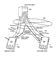
- FIG. 1 is a schematic diagram showing an overall configuration of a network system 1 according to the present embodiment.
- network system 1 includes mobile phones 100A, 100B, 100C, a matching server 400, the Internet (first network) 500, and a carrier network (second network) 700.
- the network system 1 according to the present embodiment includes a car navigation device 200 mounted on a vehicle 250 and a personal computer (PC) 300.
- PC personal computer
- the network system 1 includes a first mobile phone 100A, a second mobile phone 100B, and a third mobile phone 100C. Will be described. Further, when a configuration or function common to each of the mobile phones 100A, 100B, and 100C is described, they are also collectively referred to as “mobile phone 100”. When the configurations and functions common to the mobile phones 100A, 100B, 100C, the car navigation device 200, and the personal computer 300 are described, they are also collectively referred to as “communication terminals”.
- the mobile phone 100 is configured to be connectable to the carrier network 700.
- the car navigation device 200 is configured to be connectable to the Internet 500.
- the personal computer 300 is configured to be connectable to the Internet 500 via a LAN (Local Area Network) 350 or a WAN (Wide Area Network).
- the matching server 400 is configured to be connectable to the Internet 500.
- the first mobile phone 100A, the second mobile phone 100B, and the third mobile phone 100C can make a voice call with each other via the carrier network.
- the first mobile phone 100A, the second mobile phone 100B, the third mobile phone 100C, the car navigation device 200, and the personal computer 300 can communicate with each other via the carrier network 700 and the Internet 500. Is possible.
- the mobile phone 100, the car navigation device 200, and the personal computer 300 are assigned telephone numbers for specifying their own terminals. That is, the mobile phone 100, the car navigation device 200, and the personal computer 300 can store the telephone numbers of other communication terminals in an internal recording medium, and via the carrier network 700 and the Internet 500 based on the telephone numbers. Thus, a voice call can be performed with the other communication terminal.
- the first mobile phone 100A, the second mobile phone 100B, the third mobile phone 100C, the car navigation device 200, and the personal computer 300 exchange data with each other via the carrier network 700 and the Internet 500. Can be sent and received.
- identification information for example, a telephone number, a mail address, an IP (Internet Protocol) address, etc.
- identification information for example, a telephone number, a mail address, an IP (Internet Protocol) address, etc.
- the mobile phone 100, the car navigation device 200, and the personal computer 300 can store identification information of other communication terminals in an internal recording medium, and the carrier network 700, the Internet 500, and the like can be stored based on the identification information.
- the data can be transmitted / received to / from the other communication terminal.
- the mobile phone 100, the car navigation device 200, and the personal computer 300 may perform data transmission / reception with other communication terminals using an IP address temporarily assigned when accessing the Internet 500.
- an IP address is assigned by the matching server 400 or another server device (not shown). Details of the IP address assignment process are well known, and therefore the description will not be repeated here.
- mobile phone 100, car navigation device 200, and personal computer 300 can directly transmit and receive data to and from each other via a network by using an IP address assigned to the mobile phone 100, car navigation device 200, and personal computer 300.
- IP address assigned to the mobile phone 100, car navigation device 200, and personal computer 300 Is possible. That is, the mobile phone 100, the car navigation device 200, and the personal computer 300 included in the network system 1 according to the present embodiment can constitute a so-called P2P (Pear to Pear) type network.
- P2P Near to Pear
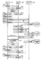
- FIG. 2 is a sequence diagram showing an outline of the operation in the network system 1.
- FIG. 3 is an image diagram showing a data flow in the network system 1.
- the communication terminal starts a voice call in response to a command (first command) for starting a voice call from the user. For example, the communication terminal starts a voice call based on the telephone number of the other party stored in the memory. Thereafter, the communication terminal accepts a command for starting P2P communication during a voice call, and starts P2P communication with the other party during the voice call.
- each of the communication terminals acquires each other's IP address via matching server 400, and then performs P2P type data transmission / reception based on the IP address.
- each of the communication terminals receives an IP address via a chat room (hereinafter also simply referred to as a room) generated in matching server 400.
- a chat room hereinafter also simply referred to as a room
- first mobile phone 100A generates a new chat room
- second mobile phone 100B in voice communication with first mobile phone 100A enters the chat room.
- first mobile phone 100A (terminal A in FIG. 2) first accepts a voice call partner selection from the user.
- First mobile phone 100A makes a call (phone call) to selected second mobile phone 100B (step S002).
- Second mobile phone 100B outputs a ring tone from the speaker in response to a call from first mobile phone 100A.
- Second mobile phone 100B responds to the call (telephone response) in response to a user operation (step S004).
- the first mobile phone 100A and the second mobile phone 100B perform voice call control (step S006). Thereby, the user of the first mobile phone 100A and the user of the second mobile phone 100B can enjoy a voice call.
- FIG. 4 is an image diagram showing the touch panel 104 during a voice call.
- the first mobile phone 100A is displayed on the touch panel 104 with a hand-drawn button 104A (P2P communication start button or chat communication start button). Is displayed (step S008).
- the hand-drawn button 104A is a software button for starting P2P communication with the other party of the voice call in parallel with the voice call during the voice call.
- first mobile phone 100A starts P2P communication.
- the first mobile phone 100A may cause one of the hardware buttons (button 110 in FIG. 6) to play the role of a hand-drawn button during a voice call (step S008).
- Other functions may be assigned to the button other than during a voice call. That is, when the user presses the hardware button (step S012), the first mobile phone 100A starts connection processing for P2P communication.
- the second mobile phone 100B has a hand-drawn button 104A (P2P communication start button or chat communication start) on its touch panel 104. Button) is displayed (step S010).
- the hand-drawn button 104A is a software button for starting P2P communication with the other party of the voice call in parallel with the voice call during the voice call. That is, when the user touches hand-drawn button 104A (step S020), second mobile phone 100B starts P2P communication.
- the second mobile phone 100B may also give the hand-drawn button the role of one of the hardware buttons during a voice call (step S010). Other functions may be assigned to the button other than during a voice call. That is, when the user presses the hardware button (step S020), the second mobile phone 100B starts connection processing for P2P communication.
- step S012 when the hand-drawn button 104A is pressed (step S012), the first mobile phone 100A activates the application for P2P communication.
- the first mobile phone 100A displays a window for P2P communication on the touch panel 104.
- First mobile phone 100A generates room names from the phone numbers of first mobile phone 100A and second mobile phone 100B. Based on the room name, first mobile phone 100A checks whether or not room AB exists in matching server 400 (step S014).
- the first mobile phone 100A transmits a generation request for generating (opening) a new room to the matching server 400 (step S016). More specifically, first mobile phone 100A transmits a generation request including a room name to matching server 400. The matching server 400 accepts the generation request including the room name and opens a room corresponding to the room name (step S018).
- the first mobile phone 100A may acquire its own IP address from the matching server 400 when opening a room, or may be previously connected to another server or the like when connected to the Internet 500.
- the IP address may be acquired from When generating a room, matching server 400 associates and stores the room name and identification information (such as an IP address) of first mobile phone 100A.
- the user of the second mobile phone 100B is requested to press the hand-drawn button 104A by the user of the first mobile phone 100A, for example, by voice call.
- the hand-drawn button 104A is pressed by the user (step S020)
- second mobile phone 100B activates an application for P2P communication.
- the second mobile phone 100B also displays a window for P2P communication on the touch panel 104.
- Second mobile phone 100B generates a room name based on a predetermined rule based on the phone number of first mobile phone 100A and the phone number of its own mobile phone 100B.
- first mobile phone 100A and second mobile phone 100B both generate room names based on the same information. That is, the network system 1 is configured so that the room names generated by the first and second mobile phones are the same. However, the network system 1 only needs to be configured so that the first and second mobile phones can generate the same room name, and generates the room name based on the telephone numbers of the first and second mobile phones.
- the configuration is not limited.
- the second mobile phone 100B inquires of the matching server 400 whether there is a room corresponding to the room name (step S022).
- the second mobile phone 100B makes a room entry request (participation request) to the room AB to the matching server 400 (step S024).
- Matching server 400 accepts the room entry request and registers the identification information of second mobile phone 100B in association with the room name of room AB (step S026).
- the second mobile phone 100B may acquire its own IP address from the matching server 400 when entering the room, or may be previously connected to another server or the like when connected to the Internet 500.
- the IP address may be acquired from Matching server 400 stores the room name and identification information (such as an IP address) of second mobile phone 100B in association with each other when second mobile phone 100B enters the room.
- the matching server 400 notifies the first mobile phone 100A and the second mobile phone 100B that the matching process is successful (step S028). That is, matching server 400 transmits each other's identification information to first mobile phone 100A and second mobile phone 100B.
- the first mobile phone 100A and the second mobile phone 100B authenticate each other based on the other party's identification information (step S030).
- the first mobile phone 100A and the second mobile phone 100B start P2P communication (hand-drawn chat communication) as shown in FIGS. 4D and 4E (step S032). ).
- the first mobile phone 100A and the second mobile phone 100B shift to the handsfree mode or the speakerphone mode when the hand-drawn button 104A is pressed. More specifically, when the hand-drawn button 104A is pressed, the first mobile phone 100A and the second mobile phone 100B increase the speaker volume (output amplification factor) or the microphone sensitivity (input Increase the amplification factor). That is, the first mobile phone 100A and the second mobile phone 100B listen to the sound from the speaker while the user performs hand-drawn chat, that is, the user performs hand-drawn input on the touch panel 104 using the stylus pen 120. Or a mode in which sound can be input to the microphone.
- first mobile phone 100A When first mobile phone 100A receives a command for ending P2P communication from the user, first mobile phone 100A transmits a message for ending P2P communication to second mobile phone 100B (step S038). For example, when the user touches P2P end button 104C, first mobile phone 100A cancels the hands-free mode and transmits the above message to second mobile phone 100B.
- the second mobile phone 100B responds to the message and cancels the hands-free mode (step S040).
- the first mobile phone 100A and the second mobile phone 100B end the P2P communication. That is, first mobile phone 100A and second mobile phone 100B continue only voice calls.
- the first mobile phone 100A When the first mobile phone 100A receives a command for ending the voice call from the user, the first mobile phone 100A requests the second mobile phone 100B to disconnect the phone (step S042). Second mobile phone 100B responds to the request (step S044). However, when the first mobile phone 100A and the second mobile phone 100B accept an instruction to end the voice call during the P2P communication, the first mobile phone 100A and the second mobile phone 100B may end only the voice call while continuing the P2P communication. .
- each communication terminal obtains identification information (such as a telephone number) for voice communication related to the communication terminal of the other party and identification information (such as an IP address) for data communication.
- identification information such as a telephone number
- identification information such as an IP address
- each of a plurality of communication terminals in a voice call can accept a command for accepting data communication in a voice call. Therefore, each of the communication terminals can specify a voice communication partner as a data communication partner. Then, each of the communication terminals uses the matching server 400 based on the identification information for the voice call related to the voice call partner to acquire the identification information for the data communication related to the voice call partner.
- each user of the communication terminal can perform hand-drawn data communication while performing a voice call simply by pressing the hand-drawn button 104A.
- FIG. 5 is an image diagram showing an appearance of mobile phone 100 according to the present embodiment.
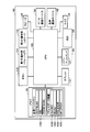
- FIG. 6 is a block diagram showing a hardware configuration of mobile phone 100 according to the present embodiment.
- mobile phone 100 includes data communication device 101 for performing data communication with other communication terminals via Internet 500, and a telephone line (carrier).
- a voice call device 102 for making a voice call with another communication terminal via a network 700, a memory 103 for storing programs and various databases, a CPU (Central Processing Unit) 106, a display 107, and an external voice.
- a speaker 109 that outputs audio
- a button 110 that receives input of various information
- a first notification unit 111 that outputs audio indicating that external communication data or a call signal has been received
- a second notification unit 112 that displays that the communication data or the call signal from the outside has been received.
- the data communication device 101 and the voice call device 102 are composed of, for example, an antenna and a signal processing circuit, and both may be realized by the same device.
- the personal computer 300 may perform hand-drawn chat communication while making an IP phone call using a single communication interface.
- the mobile phone 100 has a pen tablet 119 laid on the upper side (front side) of the display 107.
- the user can input graphic information and the like into the CPU 106 via the pen tablet 119 by using the stylus pen 120 or the like.
- the display 107 displays an image or text based on the data output from the CPU 106. That is, in the present embodiment, display 107 and pen tablet 119 constitute touch panel 104.
- the button 110 is a hardware button for receiving information from the user by a key input operation or the like.
- the button 110 includes a TEL button 110A for accepting or making a call, a P2P button 110B for accepting P2P communication or issuing P2P communication, and an address book button for calling address book data. 110D and an end button 110E for ending various processes. That is, the button 110 accepts a command to enter a chat room, a command to display the content of the mail, and the like from the user when a P2P participation request mail is received via the voice call device 102.
- the first notification unit 111 outputs a ring tone through the speaker 109 or the like. Alternatively, the first notification unit 111 has a vibration function. The first notification unit 111 outputs a voice or vibrates the mobile phone 100 when an incoming call is received or a P2P participation request mail is received.
- the second notification unit 112 includes a TEL LED (Light Emitting Diode) 112A that blinks when an incoming call arrives, and a P2P LED 112B that blinks when P2P communication is received.
- TEL LED Light Emitting Diode
- CPU 106 controls each unit of mobile phone 100. For example, various commands are received from the user via the button 110, and data is transmitted / received to / from an external communication terminal via the data communication device 101, the voice call device 102, or the network. As will be described later, the CPU 106 executes the steps shown in FIGS. 12 to 16 based on a program downloaded from the outside or stored in the memory 103 in advance.
- the data communication device 101 transmits communication data from the CPU 106 via an antenna (not shown).
- the data communication device 101 inputs the communication data received via the antenna to the CPU 106.
- the voice call device 102 transmits a voice signal from the CPU 106 via an antenna (not shown).
- the voice call device 102 inputs the voice signal received via the antenna to the CPU 106.
- the memory 103 is realized by a RAM (Random Access Memory) that functions as a working memory, a flash memory (Flash Memory) that stores a control program, image data, and the like.
- the memory 103 has various work memories 103A.
- the work memory 103A of the memory 103 includes an RCVTELNO area for storing the caller's telephone number, a SEL area for storing the memory No of the selected address, and a ROOMNAME area for storing the generated room name.
- FIG. 7A is an image diagram showing the address book data 103B stored in the memory 103.
- FIG. 7B is an image diagram showing the own terminal data 103 ⁇ / b> C stored in the memory 103.
- FIG. 7C is an image diagram showing communication partner IP address data 103D and own terminal IP address data 103E stored in the memory 103.
- address book data (AdrDB []) 103B associates a memory No. with each destination (other communication terminal).
- the address book data 103B stores a name, a telephone number, a mail address, a nickname, and the like in association with each other for each destination.
- the memory 103 stores the name of the user of the own terminal, the telephone number of the own terminal, the mail address of the own terminal, the nickname, etc. as the own terminal data (MyAdr) 103C.
- the memory 103 stores the IP address data (HIS_IPADR) 103D of the communication partner and the IP address data (MY_IPADR) 103E of the own terminal.
- IP address data HIS_IPADR
- MY_IPADR IP address data
- FIG. 8 is a block diagram showing a hardware configuration of matching server 400 according to the present embodiment.
- matching server 400 according to the present embodiment includes a CPU 405, a memory 406, a fixed disk 407, and a communication device 409 that are mutually connected by an internal bus 408.
- the memory 406 stores various types of information. For example, the memory 406 temporarily stores data necessary for executing a program in the CPU 405.
- the fixed disk 407 stores a program executed by the CPU 105 and a database.
- the CPU 405 controls each element of the matching server 400 and is a device that performs various calculations.
- the communication device 409 converts the data output from the CPU 405 into an electric signal and transmits it to the outside, converts the electric signal received from the outside into data, and inputs the data to the CPU 405. Specifically, the communication device 409 transmits data from the CPU 405 to the mobile phone 100, the car navigation device 200, and the personal computer 300 via the Internet 500, the carrier network 700, and the like. The communication device 409 inputs data received from the mobile phone 100, the car navigation device 200, or the personal computer 300 via the Internet 500 or the carrier network 700 to the CPU 405.
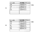
- FIG. 9A is a first image diagram showing the data structure of the room management table 406A stored in the memory 406 or the fixed disk 407 of the matching server 400.
- FIG. 9B shows the memory of the matching server 400.
- FIG. 9A is a first image diagram showing the data structure of the room management table 406A stored in the memory 406 or the fixed disk 407 of the matching server 400.
- FIG. 9B shows the memory of the matching server 400.
- room management table 406A stores the room name and the identification information of the communication terminal entering the room in association with each room. For example, at a certain point in time, referring to FIG. 9A, matching server 400 has chat room having room name AB, chat room having room name CD, chat room having room name EF, and room name GH. A chat room has been generated.
- the room name AB is determined by the communication terminal A based on the telephone number of the communication terminal A and the telephone number of the communication terminal B.
- the room name CD is determined by the communication terminal C based on the telephone number of the communication terminal C and the telephone number of the communication terminal D.
- the room name EF is determined by the communication terminal E based on the telephone number of the communication terminal E and the telephone number of the communication terminal F.
- the room name GH is determined by the communication terminal G based on the telephone number of the communication terminal G and the telephone number of the communication terminal H.
- the room management table 406A Since the communication terminal A has entered the chat room having the room name AB, the room management table 406A stores the IP address of the communication terminal A in association with the room name AB. Since the communication terminal C has entered the chat room having the room name CD, the room management table 406A stores the IP address of the communication terminal C in association with the room name CD. Since the communication terminal E has entered the chat room having the room name EF, the room management table 406A stores the IP address of the communication terminal E in association with the room name EF. Since the communication terminal G has entered the chat room having the room name GH, the room management table 406A stores the IP address of the communication terminal G in association with the room name GH.
- room management table 406A stores the IP address of communication terminal B in association with room name AB.
- the matching server 400 when the first mobile phone 100A requests the generation of a new chat room (step S016 in FIG. 2), the room name is acquired from the generation request and is stored in the room management table 406A. The room name and the IP address of first mobile phone 100A are stored in association with each other. Thereafter, when the second mobile phone 100B requests the matching server 400 to enter the chat room (step S024 in FIG. 2), the CPU 405 stores the room name and the second mobile phone 100B in the room management table 406A. Are stored in association with each other's IP address.
- the CPU 405 reads the IP address of the first mobile phone 100A and the IP address of the second mobile phone 100B corresponding to the room name from the room management table 406A.
- CPU 405 transmits the IP address of first mobile phone 100A to each second communication terminal, and transmits the IP address of second mobile phone 100B to first mobile phone 100A.
- the predetermined condition corresponds to, for example, that the number of IP addresses associated with the room name reaches a preset number, or that a preset time elapses after the room is created. To do.
- FIG. 10 is a block diagram showing a functional configuration of the network system 1 according to the present embodiment.
- network system 1 according to the present embodiment includes a first mobile phone 100A, a second mobile phone 100B, a matching server 400, the Internet 500, and a carrier network 700.
- the first mobile phone 100A includes a first communication unit 101-1, a first generation unit 1061-1, a first communication control unit 1062-1, a first memory 103-1, and a first Input unit 110-1.
- the second mobile phone 100B includes a second communication unit 101-2, a second generation unit 1061-2, a second communication control unit 1062-2, a second memory 103-2, Input unit 110-2.
- Matching server 400 includes a communication device 409, a room generation unit 4051, a room entry unit 4052, a room deletion unit 4053, and a memory 406.
- the memory 406 stores the room management table 406A.
- the communication device 409 transmits and receives data to and from the first mobile phone 100A and the second mobile phone 100B via the Internet 500 and the carrier network 700. For example, the communication device 409 inquires a generation request for generating a new room, a deletion request for deleting a room, and the existence of a room from the first mobile phone 100A, the second mobile phone 100B, or the like. Search request for entering the room and a room entry request for entering the room.
- FIG. 11 is an image diagram showing an example of a message (command) transmitted / received between the matching server 400 and the first mobile phone 100A and the second mobile phone 100B.
- the generation request is a message for requesting generation of a room
- the command name is “RM_CREATE”.
- the first mobile phone 100A or the second mobile phone 100B transmits the IP address of the first mobile phone 100A or the second mobile phone 100B and the room name of the room to be generated as a generation request.
- the matching server 400 receives the generation request and generates a new room corresponding to the room name as will be described later.
- Matching server 400 returns a message indicating whether or not the room has been successfully generated to first mobile phone 100A or second mobile phone 100B.
- the search request is a message for requesting a room search, and the command name is “RM_SEARCH”.
- the first mobile phone 100A or the second mobile phone 100A transmits the IP address of the first mobile phone 100A or the second mobile phone 100B and the room name to be searched as a search request.
- the matching server 400 receives the search request and determines whether or not the room name is stored in the room management table 406A as will be described later. Matching server 400 returns a message indicating whether or not a room having a room name exists to first mobile phone 100A or second mobile phone 100B.
- the deletion request is a message for requesting deletion of a room, and the command name is “RM_DELETE”.
- First mobile phone 100A or second mobile phone 100B transmits the IP address of first mobile phone 100A or second mobile phone 100B and the room name of the room to be deleted as a deletion request.
- the matching server 400 receives the deletion request and deletes the room corresponding to the room name from the room management table 406A. Matching server 400 returns a message indicating whether or not the room has been successfully deleted to first mobile phone 100A or second mobile phone 100B.
- the room entry request is a message for entering the room, and the command name is “RM_ENTRY”.
- the first mobile phone 100A or the second mobile phone 100B transmits the IP address of the first mobile phone 100A or the second mobile phone 100B and the room name to enter as a room entry request.
- Matching server 400 accepts the room entry request and stores the IP address of first mobile phone 100A or second mobile phone 100B in the room management table 406A in association with the room name.
- Matching server 400 replies to first mobile phone 100A or second mobile phone 100B with a message indicating whether or not the room has been successfully entered.
- the room generation unit 4051, the room entry unit 4052, and the room deletion unit 4053 are shown in FIG. 8 when the CPU 405 of the matching server 400 executes a program stored in the memory 406, the fixed disk 407, or the like. This is realized by controlling each hardware. For example, each function of the CPU 405 is realized by the CPU 405 once reading a program stored in the fixed disk 407 to the memory 406 and sequentially executing the program while reading the program from the memory 406.
- the room generation unit 4051 receives a generation request from the first mobile phone 100A via the communication device 409, for example. In response to the generation request, the room generation unit 4051 generates a new room having the room name included in the generation request. That is, the room generation unit 4051 associates the room name with the IP address of the first mobile phone 100A and stores it in the room management table 406A. The room generation unit 4051 transmits the determination result to the first mobile phone 100A via the communication device 409.
- the room entry unit 4052 receives an inquiry about the presence or absence of a chat room having a room name from the second mobile phone 100B via the communication device 409, for example.
- the room entry unit 4052 determines whether or not the room name is stored in the room management table 406A.
- the room entry unit 4052 transmits the determination result to the second mobile phone 100B via the communication device 409.
- the room entry unit 4052 receives a request to enter the chat room from the second mobile phone 100B via the communication device 409, for example.
- room entry unit 4052 stores the IP address of second mobile phone 100B in room management table 406A in association with the room name included in the entry request.
- the room entry unit 4052 transmits the IP address of another communication terminal entering the room to each communication terminal entering the room.
- the predetermined condition corresponds to, for example, that the number of IP addresses associated with the room name reaches a preset number, or that a preset time elapses after the room is created. To do.
- the room deletion unit 4053 receives a request to delete a chat room having a room name from the first mobile phone 100A via the communication device 409, for example. In response to the deletion request, the room deletion unit 4053 deletes data relating to the room name in the room management table 406A, or turns on a deletion flag corresponding to the room name in the room management table 406A. The room deletion unit 4053 transmits the determination result to the first mobile phone 100A via the communication device 409.
- First communication unit 101-1 is realized by data communication device 101 or voice call device 102 of first mobile phone 100A.
- the first memory 103-1 is realized by the memory 103 of the first mobile phone 100A.
- the first input unit 110-1 is realized by the touch panel 104 or the button 110 of the first mobile phone 100A.
- First generation unit 1061-1 and first communication control unit 1062-1 control the hardware shown in FIG. 6 by CPU 106 of first mobile phone 100A executing a program stored in memory 103 It is realized by doing.
- the first memory 103-1 includes first identification information (such as a telephone number, mail address, and IP address) for specifying the first mobile phone 100A and a second mobile phone 100B for specifying the second mobile phone 100B. Identification information (telephone number, mail address, IP address, etc.) is stored. More specifically, the first memory 103-1 stores address book data 103B, own terminal data 103C, communication partner IP address data 103D, own terminal IP address data 103E, and the like.
- first identification information such as a telephone number, mail address, and IP address
- the first generation unit 1061-1 receives a start command for starting P2P communication from the user via the first input unit 110-1 during a voice call. More specifically, the user inputs a command for starting P2P communication with a voice call partner. In response to the start command, first generation unit 1061-1 generates a new room name based on its own telephone number and the telephone number of the communication partner (second mobile phone 100B) during the voice call. .
- the first communication control unit 1062-1 inquires of the matching server 400 via the first communication unit 101-1 whether there is a chat room corresponding to the room name.
- the first communication control unit 1062-1 transmits a room entry request to the matching server 400 via the first communication unit 101-1.
- the first communication control unit 1062-1 can acquire the IP address of the partner communication terminal from the matching server 400, and can perform P2P communication via the first communication unit 101-1. become.
- the first communication control unit 1062-1 uses the first communication unit 101-1, and generates a generation request for generating a new chat room together with the room name. Transmit to matching server 400. Thereafter, when the partner communication terminal enters the chat room, the first communication control unit 1062-1 can obtain the IP address of the partner communication terminal from the matching server 400, and the first communication unit 101-1. It is possible to perform P2P communication with the communication terminal of the other party via the network.
- Second communication unit 101-2 is realized by data communication device 101 or voice call device 102 of second mobile phone 100B.
- the second memory 103-2 is realized by the memory 103 of the second mobile phone 100B.
- Second input unit 110-2 is realized by touch panel 104 or button 110 of second mobile phone 100B.
- Second generation unit 1061-2 and second communication control unit 1062-2 control the hardware shown in FIG. 5 by executing the program stored in memory 103 by CPU 106 of second mobile phone 100B. It is realized by doing.
- the second memory 103-2 includes second identification information (such as a telephone number, a mail address, and an IP address) for specifying the second mobile phone 100B and a first mobile phone 100A for specifying the first mobile phone 100A. Identification information (telephone number, mail address, IP address, etc.) is stored. More specifically, the second memory 103-2 stores address book data 103B, own terminal data 103C, communication partner IP address data 103D, own terminal IP address data 103E, and the like.
- second identification information such as a telephone number, a mail address, and an IP address
- the second generation unit 1061-2 receives a start command for starting P2P communication from the user via the second input unit 110-2 during a voice call. More specifically, the user inputs a command for starting P2P communication with a voice call partner. In response to the start command, second generation unit 1061-2 generates a new room name based on its own telephone number and the telephone number of the communication partner (first mobile phone 100A) in the voice call. .
- the second communication control unit 1062-2 inquires of the matching server 400 whether or not there is a chat room corresponding to the room name via the second communication unit 101-2.
- the second communication control unit 1062-2 transmits a room entry request to the matching server 400 via the second communication unit 101-2.
- the second communication control unit 1062-2 can acquire the IP address of the partner communication terminal from the matching server 400 and can perform P2P communication via the second communication unit 101-2. become.
- the second communication control unit 1062-2 uses the second communication unit 101-2 to generate a generation request for generating a new chat room together with the room name. Transmit to matching server 400. Thereafter, when the partner communication terminal enters the chat room, the second communication control unit 1062-2 can acquire the IP address of the partner communication terminal from the matching server 400, and the second communication unit 101-2. It is possible to perform P2P communication with the communication terminal of the other party via the network.
- the first generation unit 1061-1 generates a room name in which the first phone number of the first mobile phone 100A and the second phone number of the second mobile phone 100B are simply arranged. Since the telephone number is data unique to each terminal, the room name in which the first telephone number and the second telephone number are arranged is data unique to each group, and the room name of the other group. There is no duplication.
- step S022 in FIG. 2 it is preferable to confirm the presence / absence of a room with respect to the room name in which the phone number is replaced before and after.
- the first generation unit 1061-1 uses other identification information (e-mail address, nickname, etc.) corresponding to the telephone number of the first mobile phone 100A and other identification information of the second mobile phone 100B. Room names arranged in alphabetical order may be generated.
- the first generation unit 1061-1 may encrypt the first telephone number and the second telephone number using a hash function or the like, and generate the room name by arranging them.
- the encryption method is more difficult to restore the original data.
- the phone number is preferably encrypted using an irreversible function.
- the second generation unit 1061-2 generates a room name using the same method as the first generation unit 1061-1. For this reason, the invited second mobile phone 100B can generate the room name by itself. That is, it is not necessary for the user of the first mobile phone 100A to notify the user of the second mobile phone 100B of the room name before starting the P2P communication.
- the users of the first mobile phone 100A and the second mobile phone 100B do not need to input a command for selecting a P2P communication partner. Further, the user does not need to think about the room name or input the room name. That is, the effort that the user of the first mobile phone 100A and the second mobile phone 100B performs before starting P2P communication is greatly reduced.
- each communication terminal generates a room name that does not overlap with the room name of another chat room, so that the user of each communication terminal can create a room in another chat room. There is no need to think of a room name that does not overlap with the name.
- network system 1 according to the present embodiment can save the user from entering the room name of the chat room.
- FIG. 12 is a flowchart showing a processing procedure of communication processing in mobile phone 100 according to the present embodiment.
- CPU 106 displays a standby screen on display 107 (step S102).
- CPU 106 determines whether or not address book button 110D (or a software button for the address book displayed on touch panel 104) has been operated (step S104).
- address book button 110D is operated (YES in step S104)
- CPU 106 executes call processing (step S200). The calling process (step S200) will be described later.
- step S106 determines whether there is a telephone call (incoming call) (step S106). When there is a telephone call (YES in step S106), CPU 106 executes an incoming call process (step S500). The incoming call process (step S500) will be described later. If there is no telephone call (NO in step S106), CPU 106 repeats the processing from step S104.
- FIG. 13 is a flowchart showing a processing procedure of call processing in mobile phone 100 according to the present embodiment.
- step S104 when address book button 110D is operated (YES in step S104), CPU 106 causes display 107 to display a list of address books based on address book data 103B (step S202). ).
- the user selects a partner communication terminal in the TEL call by pressing the button 110 (or by touching one of the records of the partner terminal displayed on the touch panel 104) (step S204). That is, CPU 106 accepts a communication terminal selection command via button 110 or touch panel 104.
- the CPU 106 determines whether or not the TEL button 110A (or a software button for starting a voice call displayed on the touch panel 104) is operated in a state where the other communication terminal is selected (step S206).
- TEL button 110A is operated (YES in step S206)
- CPU 106 executes a TEL call process (step S300).
- the TEL call processing (300) will be described later.
- step S206 CPU 106 determines whether end button 110E (or a software button for canceling the voice call displayed on touch panel 104) is operated. Judgment is made (step S208). When end button 110E is operated (YES in step S208), CPU 106 ends the calling process and repeats the process from step S102. If the end button is not operated (NO in step S208), CPU 106 repeats the processing from step S206.
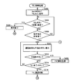
- FIG. 14 is a flowchart showing a processing procedure of TEL call processing in mobile phone 100 according to the present embodiment.
- CPU 106 uses telephone call device 102 to select the telephone number of the selected communication terminal (SEL in memory 103).
- the telephone number corresponding to the memory No. stored in (No.) is called (step S302). That is, CPU 106 makes a call to the partner communication terminal selected from the address book via data communication device 101 or voice call device 102.
- CPU 106 determines whether or not TEL button 110A (or a software button for ending the voice call displayed on touch panel 104) has been operated (step S304). If the TEL button is operated (YES in step S304), CPU 106 interrupts the TEL call (step S306) and repeats the processing from step S102.
- step S304 CPU 106 waits for a response from the partner communication terminal (step S308). If there is no response from the partner communication terminal (NO in step S308), CPU 106 repeats the processing from step S304.
- step S310 If there is a response from the partner communication terminal (YES in step S308), CPU 106 performs call control (step S310). Thereafter, until step S316, as shown in FIG. 4A, CPU 106 accepts a command for starting hand-drawn chat communication (in this embodiment, P2P communication) on touch panel 104.
- the hand-drawn button 104A is displayed.
- the CPU 106 uses any one of the hardware buttons 110 as the hand-drawn button 104A.
- the CPU 106 also displays a TEL end button 104B for ending the call control on the touch panel 104 during the call control.
- CPU 106 executes P2P start processing (step S400) when hand-drawn button 104A is pressed (YES in step S312).
- P2P start process (S400) will be described later.
- the CPU 106 determines whether the TEL end button 104B on the touch panel 104 is pressed or whether a TEL end signal is received from the outside. (Step S314).
- CPU 106 repeats the processing from step S310 when the TEL end button 104B is not pressed and when the TEL end signal is not received (NO in step S314).
- step S3134 When the TEL end button 104B is pressed or when a TEL end signal is received (YES in step S314), the CPU 106 disconnects the TEL call (step S316). CPU 106 repeats the processing from step S102.
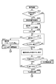
- FIG. 15 is a flowchart showing a processing procedure of P2P communication processing in mobile phone 100 according to the present embodiment.
- step S ⁇ b> 312, or YES in step S ⁇ b> 520 CPU 106 increases the audio output from speaker 109 and microphone 108. Is increased (step S402). That is, the CPU 106 shifts the communication terminal to the “hands-free mode” or the “speaker phone mode”.
- the CPU 106 generates a chat room name from the telephone number (RCVTELNO value) of the partner communication terminal and the telephone number (MyAdr.TELNo value) of the own terminal based on a predetermined rule (step S404). For example, the CPU 106 substitutes the return value of the HASH function, HASH (RCVTELNO, MyAdr.TELNo), into RMNM.
- the CPU 106 connects to the Internet 500 via the data communication device 101 (step S406). At this time, the mobile phone 100 is assigned an IP address.
- the CPU 106 inquires of the matching server 400 via the data communication device 101 whether there is a chat room having the chat room name stored in the RMNM (step S408).
- step S410 If there is still no chat room having the chat room name stored in the RMNM in the matching server 400 (NO in step S408), the CPU 106 passes the data communication device 101 to the matching server 400. A generation request for generating a chat room having the RMNM chat room name is transmitted (step S410).
- the CPU 106 determines whether or not the P2P button has been operated by the user via the button 110 (step S412). That is, CPU 106 determines whether or not a command for interrupting P2P communication has been received from the user.
- CPU 106 deletes to delete the chat room having the RMNM chat room name in matching server 400 via data communication device 101.
- the request is transmitted (step S414), and the processing from step S102 is repeated.
- CPU 106 determines whether the partner communication terminal has entered the generated chat room (step S416). CPU 106 repeats the processing from step S412 when the partner communication terminal does not enter the generated chat room (NO in step S416).
- step S416 If the partner communication terminal enters the generated chat room (YES in step S416), CPU 106 stores the received IP address of the partner communication terminal in HIS_IPADR (step S418). The CPU 106 transmits a deletion request for deleting the chat room having the chat room name of RMNM to the matching server 400 via the data communication device 101 (step S420), and as shown in FIG. Communication control is started (step S422).
- step S408 CPU 106 matches matching server 400 via data communication device 101. Enter the chat room (step S432). That is, the CPU 106 transmits a room entry request to the matching server 400 via the data communication device 101.
- CPU 106 acquires the IP address of the other party for P2P communication from matching server 400 via data communication device 101 (step S434).
- the CPU 106 stores the other party's IP address in the HIS_IPADR and starts control of P2P communication as shown in FIG. 4D (step S422).
- CPU 106 determines whether or not the user has operated P2P end button 104C (see FIG. 4) via button 110 or chat end button 104C, or has received a communication end notification from the partner communication terminal in P2P communication. Is determined (step S424). That is, the CPU 106 determines whether or not a command for interrupting the P2P communication has been received from the user. When the P2P button is not operated (NO in step S424), CPU 106 repeats the processing from step S422.
- step S424 If the P2P button is operated (YES in step S424), the CPU 106 disconnects the connection to the Internet 500 (step S426). CPU 106 cancels “hands-free mode” or “speakerphone mode” (step S428). CPU 106 repeats the processing from step S310.
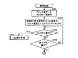
- FIG. 16 is a flowchart showing a processing procedure of incoming call processing in mobile phone 100 according to the present embodiment.
- CPU 106 determines whether or not the telephone number of the caller is notified (step S502). If the caller's telephone number has not been notified (NO in step S502), CPU 106 executes the processing from step S506.
- CPU 106 stores the caller's telephone number in RCVTELNO (step S504).
- the CPU 106 activates the first notification unit 111, that is, outputs a ringtone through the speaker 109 or vibrates the mobile phone 100 with a vibration function (step S506).
- the CPU 106 activates the second notification unit 112, that is, blinks the TEL LED 112A (step S508).
- step S510 determines whether or not the incoming call is finished.
- the CPU 106 stops the first notification unit 111, that is, stops the output of the ring tone through the speaker 109 or the like, or vibrates.
- the vibration of the mobile phone 100 is stopped (step S512).
- the CPU 106 operates the second notification unit 112, that is, turns on the TEL LED 112A (step S514), registers the caller number and the incoming time of the communication partner terminal in the memory 103 as the incoming call history, and step S102. Repeat the process from.
- CPU 106 determines whether or not TEL button 110A has been operated (step S516) when the incoming call has not ended (NO in step S510). If the TEL button 110A is not operated (NO in step S516), CPU 106 repeats the processing from step S510.
- CPU 106 performs call control when TEL button 110A is operated (YES in step S516) (step S518). Thereafter, until step S522, as shown in FIG. 4A, CPU 106 accepts an instruction for starting hand-drawn chat communication (in this embodiment, P2P communication) on touch panel 104.
- the hand-drawn button 104A is displayed.
- the CPU 106 uses any hardware button 110 as the hand-drawn button 104A.
- the CPU 106 also displays a TEL end button 104B for ending the call control on the touch panel 104 during the call control.
- step S400 When the hand-drawn button 104A is pressed (YES in step S520), the CPU 106 executes the above-described P2P start process (step S400).
- CPU 106 determines whether or not TEL end button 104B on touch panel 104 has been pressed, or whether or not a TEL end signal has been received from the outside, when hand-drawn button 104A is not pressed (NO in step S520). (Step S522).
- step S522 When the TEL end button 104B is not pressed and the TEL end signal is not received (NO in step S522), the CPU 106 repeats the processing from step S518.
- CPU 106 disconnects the TEL call when TEL end button 104B is pressed or when a TEL end signal is received (YES in step S522) (step S524). CPU 106 repeats the processing from step S102.
- FIG. 17 is a flowchart showing a processing procedure of response processing in matching server 400 according to the present embodiment.
- CPU 405 of matching server 400 waits for a message from first mobile phone 100A via communication device 409 (step S902).
- CPU 405 determines whether the message is a generation request for generating a chat room (step S904).
- step S904 If the message is a generation request for generating a chat room (YES in step S904), CPU 406 determines whether or not the room name included in the generation request exists in room management table 406A (step S904). S906). If the room name exists in room management table 406A (YES in step S906), CPU 406 notifies that room generation has failed (step S932), and repeats the processing from step S902.
- step S906 If the room name does not exist in the room management table 406A (NO in step S906), the CPU 406 generates a room with the room name (step S908). That is, the CPU 406 stores the room name and the caller IP address included in the generation request in association with each other in the room management table 406A. The CPU 406 notifies the caller's IP address that the room has been successfully generated (step S910), and repeats the processing from step S902.
- the CPU 406 determines whether the message is a search request for searching for a room name (step S912).
- step S912 If the message is a search request for searching for a chat room (YES in step S912), it is determined whether or not the room name included in the search request exists in room management table 406A (step S914). . If the room name exists in room management table 406A (YES in step S914), CPU 406 notifies the requesting IP address that the room has been found (step S910), and performs the processing from step S902. repeat.
- step S914 If the room name does not exist in room management table 406A (NO in step S914), CPU 406 notifies that the room name is not found in the requesting IP address (step S932), and the processing from step S902 is performed. repeat.
- the CPU 406 determines whether the message is a deletion request for deleting a chat room (step S916).
- CPU 406 associates the request source IP address with the room name included in the deletion request, and manages room management table 406A. It is determined whether or not it is stored in (step S918). That is, CPU 406 determines whether or not the requesting communication terminal is a communication terminal that has already entered the chat room.
- CPU 406 deletes the chat room with the room name (Ste S920).
- the CPU 406 notifies the requesting IP address that the chat room has been successfully deleted (step S910), and repeats the processing from step S902.
- step S928 If the IP address of the request source is not stored in the room management table 406A in association with the room name included in the deletion request (NO in step S918), the CPU 406 displays the chat room IP address in the request source IP address. Notifying that the deletion has failed (step S932), the processing from step S902 is repeated.
- step S916 determines whether the message is a request for entering the chat room (step S922).
- Step S922 If the message is a room entry request for entering the chat room (YES in step S922), CPU 406 determines whether the room name included in the room entry request is stored in room management table 406A. (Step S924). When the room name included in the room entry request is stored in room management table 406A (YES in step S924), CPU 406 registers the IP address of the request source in room management table 406A in association with the room name. (Step S926).
- the CPU 406 transmits the IP address of the request source to the IP address associated with the room name and already registered in the room management table 406A via the communication device 409 (step S928).
- the CPU 406 transmits the IP address already registered in the room management table 406A in association with the room name to the requesting IP address via the communication device 409 (step S930). Then, the CPU 406 repeats the processing from step S902.
- step S922 when the message is not an entry request for entering a chat room (NO in step S922), and the room name included in the entry request is not stored in room management table 406A (in step S924). If NO, CPU 406 transmits an error message to the requesting IP address (step S932), and repeats the processing from step S902.
- the program code itself read from the storage medium realizes the functions of the above-described embodiment, and the storage medium storing the program code constitutes the present invention.
- a storage medium for supplying the program code for example, hard disk, optical disk, magneto-optical disk, CD-ROM, CD-R, magnetic tape, nonvolatile memory card (IC memory card), ROM (mask ROM, flash) EEPROM, etc.) can be used.
- the function expansion is performed based on the instruction of the program code. It goes without saying that the CPU or the like provided in the board or the function expansion unit performs part or all of the actual processing and the functions of the above-described embodiments are realized by the processing.
- 1 network system 100, 100A, 100B, 100C mobile phone, 101 first communication device, 102 second communication device, 103, 103-1, 103-2 memory, 103A, 103A-1, 103A-2 work memory , 103B, 103B-1, 103B-2, address book data, 103C, 103C-1, 103C-2 own terminal data, 103D, 103D-1, 103D-2, communication partner IP address data, 103E, 103E-1, 103E -2 IP address data of own terminal, 106, 106-1, 106-2 CPU, 1061, 1061-1, 1061-2 generation unit, 1062, 1062-1, 1062-2 communication control unit, 107 display, 108 microphone 109 Speaker 110 10-1, 110-2 input unit, 200 car navigation device, 300 personal computer, 400 matching server, 405A room generation unit, 405B room entry unit, 405C room deletion unit, 406 memory, 406A room management table, 407 fixed disk, 408 Internal bus, 409 communication device, 500 Internet, 700 carrier network
Landscapes
- Engineering & Computer Science (AREA)
- Computer Networks & Wireless Communication (AREA)
- Signal Processing (AREA)
- Multimedia (AREA)
- Business, Economics & Management (AREA)
- General Business, Economics & Management (AREA)
- Human Computer Interaction (AREA)
- Telephonic Communication Services (AREA)
- Telephone Function (AREA)
Abstract
Description
まず、ネットワークシステム1の全体構成について説明する。図1は、本実施の形態に係るネットワークシステム1の全体構成を示す概略図である。図1を参照して、ネットワークシステム1は、携帯電話100A,100B,100Cと、マッチングサーバ400と、インターネット(第1のネットワーク)500と、キャリア網(第2のネットワーク)700とを含む。また、本実施の形態に係るネットワークシステム1は、車両250に搭載されるカーナビゲーション装置200と、パーソナルコンピュータ(PC;Personal Computer)300とを含む。
次に、本実施の形態に係るネットワークシステム1の動作概要について説明する。図2は、ネットワークシステム1における動作概要を示すシーケンス図である。図3は、ネットワークシステム1におけるデータの流れを示すイメージ図である。
<携帯電話100のハードウェア構成>
本実施の形態に係る通信端末の一例である携帯電話100のハードウェア構成について説明する。図5は、本施の形態に係る携帯電話100の外観を示すイメージ図である。図6は、本施の形態に係る携帯電話100のハードウェア構成を示すブロック図である。
次に、本実施の形態に係るマッチングサーバ400のハードウェア構成について説明する。図8は、本実施の形態に係るマッチングサーバ400のハードウェア構成を示すブロック図である。図8を参照して、本実施の形態に係るマッチングサーバ400は、相互に内部バス408で接続されたCPU405と、メモリ406と、固定ディスク407と、通信デバイス409とを含む。
図10は、本実施の形態に係るネットワークシステム1の機能構成を示すブロック図である。図10を参照して、本実施の形態に係るネットワークシステム1は、第1の携帯電話100Aと、第2の携帯電話100Bと、マッチングサーバ400と、インターネット500と、キャリア網700とを含む。
まず、マッチングサーバ400が有する機能について説明する。前述したように、メモリ406は、ルーム管理テーブル406Aを記憶する。
次に、第1の携帯電話100Aが有する機能について説明する。第1の通信部101-1は、第1の携帯電話100Aのデータ通信デバイス101あるいは音声通話デバイス102によって実現される。第1のメモリ103-1は、第1の携帯電話100Aのメモリ103によって実現される。第1の入力部110-1は、第1の携帯電話100Aのタッチパネル104やボタン110によって実現される。第1の生成部1061-1および第1の通信制御部1062-1は、第1の携帯電話100AのCPU106がメモリ103に記憶されるプログラムを実行して図6に示される各ハードウェアを制御することによって実現される。
次に、第2の携帯電話100Bが有する機能について説明する。第2の通信部101-2は、第2の携帯電話100Bのデータ通信デバイス101あるいは音声通話デバイス102によって実現される。第2のメモリ103-2は、第2の携帯電話100Bのメモリ103によって実現される。第2の入力部110-2は、第2の携帯電話100Bのタッチパネル104やボタン110によって実現される。第2の生成部1061-2および第2の通信制御部1062-2は、第2の携帯電話100BのCPU106がメモリ103に記憶されるプログラムを実行して図5に示される各ハードウェアを制御することによって実現される。
ここで、第1の生成部1061-1、第2の生成部1061-2によるルーム名の生成方法について説明する。
次に、本実施の形態に係る携帯電話100における通信処理について説明する。図12は、本実施の形態に係る携帯電話100における通信処理の処理手順を示すフローチャートである。
次に、本実施の形態に係る携帯電話100における発呼処理について説明する。図13は、本実施の形態に係る携帯電話100における発呼処理の処理手順を示すフローチャートである。
次に、本実施の形態に係る携帯電話100におけるTEL発呼処理について説明する。図14は、本実施の形態に係る携帯電話100におけるTEL発呼処理の処理手順を示すフローチャートである。
次に、本実施の形態に係る携帯電話100におけるP2P通信処理について説明する。図15は、本実施の形態に係る携帯電話100におけるP2P通信処理の処理手順を示すフローチャートである。
次に、本実施の形態に係る携帯電話100における着呼処理について説明する。図16は、本実施の形態に係る携帯電話100における着呼処理の処理手順を示すフローチャートである。
次に、本実施の形態に係るマッチングサーバ400における応答処理について説明する。図17は、本実施の形態に係るマッチングサーバ400における応答処理の処理手順を示すフローチャートである。
本発明は、システム或いは装置にプログラムを供給することによって達成される場合にも適用できることはいうまでもない。そして、本発明を達成するためのソフトウェアによって表されるプログラムを格納した記憶媒体を、システム或いは装置に供給し、そのシステム或いは装置のコンピュータ(又はCPUやMPU)が記憶媒体に格納されたプログラムコードを読出し実行することによっても、本発明の効果を享受することが可能となる。
Claims (7)
- 他の通信端末と通信するための通信端末(100)であって、
第1の通信デバイス(101)と、
第2の通信デバイス(102)と、
スピーカ(109)と、
マイク(108)と、
プロセッサ(106)とを備え、
前記プロセッサは、
前記第1の通信デバイスと前記スピーカと前記マイクとを用いて、前記他の通信端末との音声通話を行い、
前記他の通信端末との音声通話中に、データ通信を開始するための命令を受け付け、
前記命令に応じて、前記音声通話を行いながら、前記第2の通信デバイスを用いて、前記他の通信端末とのデータ通信を行う、通信端末。 - タッチパネル(104)をさらに備え、
前記プロセッサは、
前記他の通信端末とのデータ通信中に、前記タッチパネルを介して第1の手描き画像の入力を受け付けて、当該第1の手描き画像を前記第2の通信デバイスを介して当該他の通信端末へと送信し、
前記他の通信端末との前記データ通信中に、前記第2の通信デバイスを介して当該他の通信端末から第2の手描き画像を受信して、当該第2の手描き画像を前記タッチパネルに表示させる、請求項1に記載の通信端末。 - 前記プロセッサは、前記他の通信端末との音声通話中に、前記タッチパネルに前記データ通信を開始するための命令を受け付けるためのソフトウェアボタンを表示させる、請求項2に記載の通信端末。
- ハードウェアボタンをさらに備え、
前記プロセッサは、前記他の通信端末との音声通話中に、前記ハードウェアボタンを介して、前記データ通信を開始するための命令を受け付ける、請求項1に記載の通信端末。 - 前記プロセッサは、前記データ通信を開始するときに、前記通信端末をハンズフリーモードへと移行させる、請求項1に記載の通信端末。
- 第1および第2の通信デバイスとスピーカとマイクとプロセッサとを含む通信端末における通信方法であって、
前記プロセッサが、前記第1の通信デバイスと前記スピーカと前記マイクとを用いて、前記他の通信端末との音声通話を行うステップと、
前記プロセッサが、前記他の通信端末との音声通話中に、データ通信を開始するための命令を受け付けるステップと、
前記プロセッサが、前記命令に応じて、前記音声通話を行いながら、前記第2の通信デバイスを用いて、前記他の通信端末とのデータ通信を行うステップとを備える、通信方法。 - 第1および第2の通信デバイスとスピーカとマイクとプロセッサとを含む通信端末に通信させるための通信プログラムを記録したコンピュータ読取可能な記録媒体であって、
前記通信プログラムは、前記プロセッサに、
前記第1の通信デバイスと前記スピーカと前記マイクとを用いて、前記他の通信端末との音声通話を行うステップと、
前記他の通信端末との音声通話中に、データ通信を開始するための命令を受け付けるステップと、
前記命令に応じて、前記音声通話を行いながら、前記第2の通信デバイスを用いて、前記他の通信端末とのデータ通信を行うステップとを実行させる、通信プログラムを記録したコンピュータ読取可能な記録媒体。
Priority Applications (2)
| Application Number | Priority Date | Filing Date | Title |
|---|---|---|---|
| CN2011800097711A CN102754419A (zh) | 2010-02-16 | 2011-01-26 | 通信终端、通信方法以及记录有通信程序的计算机可读取的记录介质 |
| US13/578,984 US20120309367A1 (en) | 2010-02-16 | 2011-01-26 | Communication terminal, communication method, and computer readable storage medium having communication program stored therein |
Applications Claiming Priority (2)
| Application Number | Priority Date | Filing Date | Title |
|---|---|---|---|
| JP2010031204A JP2011171809A (ja) | 2010-02-16 | 2010-02-16 | 通信端末、通信方法、および通信プログラム |
| JP2010-031204 | 2010-02-16 |
Publications (1)
| Publication Number | Publication Date |
|---|---|
| WO2011102196A1 true WO2011102196A1 (ja) | 2011-08-25 |
Family
ID=44482795
Family Applications (1)
| Application Number | Title | Priority Date | Filing Date |
|---|---|---|---|
| PCT/JP2011/051438 Ceased WO2011102196A1 (ja) | 2010-02-16 | 2011-01-26 | 通信端末、通信方法、および通信プログラムを記録したコンピュータ読取可能な記録媒体 |
Country Status (4)
| Country | Link |
|---|---|
| US (1) | US20120309367A1 (ja) |
| JP (1) | JP2011171809A (ja) |
| CN (1) | CN102754419A (ja) |
| WO (1) | WO2011102196A1 (ja) |
Families Citing this family (4)
| Publication number | Priority date | Publication date | Assignee | Title |
|---|---|---|---|---|
| JP5658547B2 (ja) * | 2009-12-29 | 2015-01-28 | シャープ株式会社 | ネットワークシステム、通信方法、および通信端末 |
| JP6144550B2 (ja) * | 2013-06-26 | 2017-06-07 | 京セラ株式会社 | ユーザ端末及びプロセッサ |
| KR101982163B1 (ko) * | 2017-08-22 | 2019-05-24 | 라인 가부시키가이샤 | 인터넷 전화 서비스의 통화 자동 연결 방법 및 시스템 |
| JP7246870B2 (ja) * | 2018-06-29 | 2023-03-28 | Line株式会社 | 送信先決定方法、送信先決定装置、送信先決定プログラム |
Citations (3)
| Publication number | Priority date | Publication date | Assignee | Title |
|---|---|---|---|---|
| JPH08116352A (ja) * | 1994-10-17 | 1996-05-07 | Hitachi Ltd | 情報処理装置 |
| JP2000261857A (ja) * | 1999-03-10 | 2000-09-22 | Denso Corp | 携帯電話装置 |
| JP2003234842A (ja) * | 2001-10-02 | 2003-08-22 | Ia Link Systems Co Ltd | リアルタイム手書き通信システム |
Family Cites Families (6)
| Publication number | Priority date | Publication date | Assignee | Title |
|---|---|---|---|---|
| US7224991B1 (en) * | 2000-09-12 | 2007-05-29 | At&T Corp. | Method and system for handwritten electronic messaging |
| US7650170B2 (en) * | 2004-03-01 | 2010-01-19 | Research In Motion Limited | Communications system providing automatic text-to-speech conversion features and related methods |
| US8094938B2 (en) * | 2004-04-02 | 2012-01-10 | Nokia Corporation | Apparatus and method for handwriting recognition |
| KR100662360B1 (ko) * | 2004-10-04 | 2007-01-02 | 엘지전자 주식회사 | 그룹 통신 기능을 갖는 이동 통신 단말기를 이용한 데이터 통신 방법 |
| US9026117B2 (en) * | 2006-05-16 | 2015-05-05 | Aylus Networks, Inc. | Systems and methods for real-time cellular-to-internet video transfer |
| US8704863B2 (en) * | 2010-04-07 | 2014-04-22 | Apple Inc. | Transitioning between circuit switched calls and video calls |
-
2010
- 2010-02-16 JP JP2010031204A patent/JP2011171809A/ja active Pending
-
2011
- 2011-01-26 WO PCT/JP2011/051438 patent/WO2011102196A1/ja not_active Ceased
- 2011-01-26 US US13/578,984 patent/US20120309367A1/en not_active Abandoned
- 2011-01-26 CN CN2011800097711A patent/CN102754419A/zh active Pending
Patent Citations (3)
| Publication number | Priority date | Publication date | Assignee | Title |
|---|---|---|---|---|
| JPH08116352A (ja) * | 1994-10-17 | 1996-05-07 | Hitachi Ltd | 情報処理装置 |
| JP2000261857A (ja) * | 1999-03-10 | 2000-09-22 | Denso Corp | 携帯電話装置 |
| JP2003234842A (ja) * | 2001-10-02 | 2003-08-22 | Ia Link Systems Co Ltd | リアルタイム手書き通信システム |
Also Published As
| Publication number | Publication date |
|---|---|
| JP2011171809A (ja) | 2011-09-01 |
| US20120309367A1 (en) | 2012-12-06 |
| CN102754419A (zh) | 2012-10-24 |
Similar Documents
| Publication | Publication Date | Title |
|---|---|---|
| KR101203248B1 (ko) | 네트워크 시스템, 통신 단말기, 통신 방법 및 통신 프로그램을 기록한 컴퓨터 판독가능 기록매체 | |
| CN101292500B (zh) | 提供歌曲播放列表的移动无线通信终端、系统、方法和计算机程序产品 | |
| JP6599380B2 (ja) | 車載ハンズフリー装置およびデータ転送方法 | |
| JP5005103B1 (ja) | 通話システム | |
| WO2011102196A1 (ja) | 通信端末、通信方法、および通信プログラムを記録したコンピュータ読取可能な記録媒体 | |
| US8576834B2 (en) | Communication system | |
| JP2005130287A (ja) | 通信制御装置及び通信制御方法、通信端末装置並びに通信システム | |
| JP5354571B2 (ja) | ネットワークシステム、通信装置、通信方法、および通信プログラム | |
| KR20220033979A (ko) | 착신전환 기반의 사용자 단말의 전화번호 유지 방법 및 시스템 | |
| CN112954103B (zh) | 一种呼叫通话方法、装置、存储介质及固定电话 | |
| JP6031825B2 (ja) | 楽曲データ出力システム | |
| KR20120055843A (ko) | 컨텐츠 자동 전송을 위한 크래들 장치, 단말기, 시스템 및 방법 | |
| CN114093367B (zh) | 基于蓝牙耳机的远程控制系统及方法 | |
| CN103761302B (zh) | 信息处理方法和信息处理设备 | |
| JP4726670B2 (ja) | 情報通信機器、情報処理プログラム、および情報通信システム | |
| KR100760658B1 (ko) | 이동통신 단말기 및 그의 메시지 답장 모드 진입 방법. | |
| KR20050074745A (ko) | 통신 단말기를 이용한 계약 인증방법 및 시스템 | |
| JP5170558B2 (ja) | 通信装置および通信方法 | |
| JP6991686B2 (ja) | 情報処理装置 | |
| JP2025068248A (ja) | 端末、ブロックチェーンアドレス送信方法、ブロックチェーンアドレス受信方法及びプログラム | |
| JP3570997B2 (ja) | 通信システム、電話交換機及び通信装置 | |
| JP2018143009A (ja) | 通信サーバ | |
| JP2017199966A (ja) | 通信端末、サーバ、及び通信システム | |
| JP2008098877A (ja) | 携帯電話サービスシステム | |
| JP2015080552A (ja) | 通信システム、情報処理装置、通信システムの制御方法及び情報処理装置のプログラム |
Legal Events
| Date | Code | Title | Description |
|---|---|---|---|
| WWE | Wipo information: entry into national phase |
Ref document number: 201180009771.1 Country of ref document: CN |
|
| 121 | Ep: the epo has been informed by wipo that ep was designated in this application |
Ref document number: 11744485 Country of ref document: EP Kind code of ref document: A1 |
|
| WWE | Wipo information: entry into national phase |
Ref document number: 13578984 Country of ref document: US |
|
| NENP | Non-entry into the national phase |
Ref country code: DE |
|
| WWE | Wipo information: entry into national phase |
Ref document number: 7808/CHENP/2012 Country of ref document: IN |
|
| 122 | Ep: pct application non-entry in european phase |
Ref document number: 11744485 Country of ref document: EP Kind code of ref document: A1 |