WO2011099551A1 - 薬液注入装置および薬液注入システム - Google Patents
薬液注入装置および薬液注入システム Download PDFInfo
- Publication number
- WO2011099551A1 WO2011099551A1 PCT/JP2011/052850 JP2011052850W WO2011099551A1 WO 2011099551 A1 WO2011099551 A1 WO 2011099551A1 JP 2011052850 W JP2011052850 W JP 2011052850W WO 2011099551 A1 WO2011099551 A1 WO 2011099551A1
- Authority
- WO
- WIPO (PCT)
- Prior art keywords
- syringe
- syringe assembly
- proximity sensor
- pressing member
- flange
- Prior art date
- Legal status (The legal status is an assumption and is not a legal conclusion. Google has not performed a legal analysis and makes no representation as to the accuracy of the status listed.)
- Ceased
Links
Images


Classifications
-
- A—HUMAN NECESSITIES
- A61—MEDICAL OR VETERINARY SCIENCE; HYGIENE
- A61M—DEVICES FOR INTRODUCING MEDIA INTO, OR ONTO, THE BODY; DEVICES FOR TRANSDUCING BODY MEDIA OR FOR TAKING MEDIA FROM THE BODY; DEVICES FOR PRODUCING OR ENDING SLEEP OR STUPOR
- A61M5/00—Devices for bringing media into the body in a subcutaneous, intra-vascular or intramuscular way; Accessories therefor, e.g. filling or cleaning devices, arm-rests
- A61M5/14—Infusion devices, e.g. infusing by gravity; Blood infusion; Accessories therefor
- A61M5/142—Pressure infusion, e.g. using pumps
- A61M5/145—Pressure infusion, e.g. using pumps using pressurised reservoirs, e.g. pressurised by means of pistons
- A61M5/1452—Pressure infusion, e.g. using pumps using pressurised reservoirs, e.g. pressurised by means of pistons pressurised by means of pistons
- A61M5/14546—Front-loading type injectors
-
- A—HUMAN NECESSITIES
- A61—MEDICAL OR VETERINARY SCIENCE; HYGIENE
- A61M—DEVICES FOR INTRODUCING MEDIA INTO, OR ONTO, THE BODY; DEVICES FOR TRANSDUCING BODY MEDIA OR FOR TAKING MEDIA FROM THE BODY; DEVICES FOR PRODUCING OR ENDING SLEEP OR STUPOR
- A61M5/00—Devices for bringing media into the body in a subcutaneous, intra-vascular or intramuscular way; Accessories therefor, e.g. filling or cleaning devices, arm-rests
- A61M5/14—Infusion devices, e.g. infusing by gravity; Blood infusion; Accessories therefor
- A61M5/142—Pressure infusion, e.g. using pumps
- A61M5/145—Pressure infusion, e.g. using pumps using pressurised reservoirs, e.g. pressurised by means of pistons
- A61M5/1452—Pressure infusion, e.g. using pumps using pressurised reservoirs, e.g. pressurised by means of pistons pressurised by means of pistons
- A61M2005/14573—Pressure infusion, e.g. using pumps using pressurised reservoirs, e.g. pressurised by means of pistons pressurised by means of pistons with a replaceable reservoir for quick connection/disconnection with a driving system
-
- A—HUMAN NECESSITIES
- A61—MEDICAL OR VETERINARY SCIENCE; HYGIENE
- A61M—DEVICES FOR INTRODUCING MEDIA INTO, OR ONTO, THE BODY; DEVICES FOR TRANSDUCING BODY MEDIA OR FOR TAKING MEDIA FROM THE BODY; DEVICES FOR PRODUCING OR ENDING SLEEP OR STUPOR
- A61M2205/00—General characteristics of the apparatus
- A61M2205/14—Detection of the presence or absence of a tube, a connector or a container in an apparatus
-
- A—HUMAN NECESSITIES
- A61—MEDICAL OR VETERINARY SCIENCE; HYGIENE
- A61M—DEVICES FOR INTRODUCING MEDIA INTO, OR ONTO, THE BODY; DEVICES FOR TRANSDUCING BODY MEDIA OR FOR TAKING MEDIA FROM THE BODY; DEVICES FOR PRODUCING OR ENDING SLEEP OR STUPOR
- A61M5/00—Devices for bringing media into the body in a subcutaneous, intra-vascular or intramuscular way; Accessories therefor, e.g. filling or cleaning devices, arm-rests
- A61M5/007—Devices for bringing media into the body in a subcutaneous, intra-vascular or intramuscular way; Accessories therefor, e.g. filling or cleaning devices, arm-rests for contrast media
-
- A—HUMAN NECESSITIES
- A61—MEDICAL OR VETERINARY SCIENCE; HYGIENE
- A61M—DEVICES FOR INTRODUCING MEDIA INTO, OR ONTO, THE BODY; DEVICES FOR TRANSDUCING BODY MEDIA OR FOR TAKING MEDIA FROM THE BODY; DEVICES FOR PRODUCING OR ENDING SLEEP OR STUPOR
- A61M5/00—Devices for bringing media into the body in a subcutaneous, intra-vascular or intramuscular way; Accessories therefor, e.g. filling or cleaning devices, arm-rests
- A61M5/14—Infusion devices, e.g. infusing by gravity; Blood infusion; Accessories therefor
- A61M5/142—Pressure infusion, e.g. using pumps
- A61M5/145—Pressure infusion, e.g. using pumps using pressurised reservoirs, e.g. pressurised by means of pistons
- A61M5/1452—Pressure infusion, e.g. using pumps using pressurised reservoirs, e.g. pressurised by means of pistons pressurised by means of pistons
- A61M5/14566—Pressure infusion, e.g. using pumps using pressurised reservoirs, e.g. pressurised by means of pistons pressurised by means of pistons with a replaceable reservoir for receiving a piston rod of the pump
Definitions
- the present invention relates to a chemical solution injection device and a chemical solution injection system for injecting a chemical solution filled in a syringe into a subject.
- Medical diagnostic imaging apparatuses include a CT (Computed Tomography) scanner, an MRI (Magnetic Resonance Imaging) apparatus, a PET (Positron Emission Tomography) apparatus, an angiographic apparatus, and an MRA (MR Angio) apparatus.
- CT Computer Tomography
- MRI Magnetic Resonance Imaging
- PET PET
- angiographic apparatus an angiographic apparatus
- MRA MR Angio
- the chemical solution injector includes an injection head to which a syringe filled with a chemical solution is detachably mounted, and an injection control unit that controls the operation of the injection head.
- the syringe has a cylinder and a piston inserted into the cylinder so as to be capable of moving forward and backward, and the liquid medicine is filled in the cylinder.
- the injection head includes a clamper for fixing the cylinder to the injection head by holding a flange formed at the end of the cylinder, and a piston drive mechanism for moving the piston while the cylinder is fixed to the injection head. ing. After connecting the injection needle to the tip of the cylinder via an extension tube, puncturing the injection needle into the blood vessel of the subject, the piston is pushed into the cylinder by the piston drive mechanism, so that the drug solution filled in the syringe is given to the subject. Can be injected.
- Patent Document 1 the detection unit for detecting that the cylinder is set in the correct posture in the XYZ directions (three directions orthogonal to each other) and the piston is correctly set in the piston drive mechanism, and the syringe are correct.
- An injection device is disclosed that includes a display unit that displays a warning when not set.
- Patent Document 1 JP 2007-306990 A
- the clamper for fixing the syringe has a structure that holds the outer peripheral surface of the cylinder by pressing it from above, so even if the syringe is not set in the correct posture. It is possible to hold. Therefore, in order to detect that the syringe is correctly attached, a sensor provided for each direction of XYZ and a piston for detecting that the syringe is set in the correct posture are used as detection means. A total of four sensors that detect that the piston drive mechanism is correctly set are used. As described above, the structure of the injection apparatus becomes complicated as a result of providing four sensors only for the detection of the syringe. In addition, this number is for one syringe. For example, in the case of an injection apparatus equipped with two syringes, eight sensors are required.
- an object of the present invention is to provide a chemical solution injection device and a chemical solution injection system that can detect with a simpler configuration that a syringe is set in a correct posture.
- a drug solution injection device is a drug solution injection device in which a syringe assembly having a cylinder and a piston is detachably mounted, and a drug solution is injected from a syringe assembly to a subject by operating the mounted syringe assembly.
- a syringe assembly having a cylinder and a piston is detachably mounted, and a drug solution is injected from a syringe assembly to a subject by operating the mounted syringe assembly.
- the clamper constitutes a part of the syringe mounting portion, and includes a base member on which the flange is mounted, a flange pressing member supported by the base member so as to be rotatable between an open position and a closed position, and a flange pressing member.
- the syringe assembly is fixed by surrounding the flange with the base member and the flange pressing member locked in the closed position.
- the first detector detects that the syringe assembly is placed on the syringe placement unit.
- the second detector detects that the flange pressing member is locked at the closed position.
- the base member and the flange pressing member can have a recess for receiving the flange.
- the second detector is a proximity sensor installed on the base member, and the flange pressing member is provided with an object to be detected that is detected by the proximity sensor when the flange pressing member is in the closed position. It is preferable. In this case, the proximity sensor and the object to be detected may be arranged so that the distance between the proximity sensor and the object to be detected is minimized when the flange pressing member is in the closed position.
- the proximity sensor is a sensor that detects metal in a non-contact manner using an AC magnetic field as a detection medium, and the object to be detected includes a metal that is detected by the proximity sensor, so that the flange pressing member is closed. It can be detected with higher accuracy that the position is locked.
- the chemical solution injection device of the present invention may further include a control unit that controls the overall operation of the chemical solution injection device and a display unit that displays information.
- the control unit includes the first detector. When it is detected that the syringe assembly is placed on the syringe placement portion, and the second detector detects that the flange pressing member is locked at the closed position, the syringe assembly is attached. By displaying information indicating completion on the display unit, the operator can easily confirm that the flange pressing member is locked.
- the control unit is configured to start the operation for injecting the chemical liquid by a predetermined operation of the operator based on the display of information, thereby preventing a malfunction due to the syringe assembly not being correctly attached.
- the chemical liquid injection device of the present invention further includes a piston drive mechanism for moving the piston forward and backward, and controls when the syringe assembly mounted on the syringe syringe mounting portion is an empty syringe not filled with the chemical liquid
- the first detector detects that the syringe assembly is mounted on the syringe mounting unit, and the second detector detects that the flange pressing member is locked at the closed position. Then, it is preferable to operate the piston drive mechanism so that the piston is positioned at the forefront of the cylinder.
- the present invention also provides a chemical injection system.
- the chemical solution injection system of the present invention includes the above-described chemical solution injection device of the present invention and a syringe assembly filled with the chemical solution that is detachably attached to the chemical solution injection device.
- the first detector of the chemical injection device is a proximity sensor, and the proximity that is the first detector when the syringe assembly is placed on the syringe mounting portion of the chemical injection device.
- An object to be detected detected by the sensor may be arranged in the syringe assembly.
- the syringe assembly further includes an RFID chip in which data is recorded
- the chemical injection device further includes an RFID reader that acquires data from the RFID chip in a state where the syringe assembly is placed on the syringe placement unit.
- the RFID reader can also be configured to act as a first detector.
- the syringe assembly includes a syringe filled with a chemical solution and having a cylinder and a piston, and a protective cover into which the syringe is inserted in order to suppress expansion due to an increase in the internal pressure of the cylinder when the chemical solution is injected. May be formed on the protective cover.
- the clamper surrounds the flange of the syringe assembly over the entire circumference, so that the syringe assembly is fixed in the correct posture and position.
- the first and second detectors can detect that the syringe assembly is attached to the chemical solution injector in a correct posture.
- a proximity sensor that can detect metal in a non-contact manner is used as the second detector, and an object to be detected detected by the proximity sensor is disposed at a position that can be detected by the proximity sensor when the flange holding member is in the closed position. By doing so, it can be detected with higher accuracy that the flange holding member is locked at the closed position.
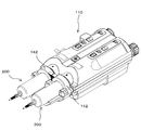
- FIG. 1 is a perspective view of a fluoroscopic imaging system according to an embodiment of the present invention. It is a perspective view of the chemical injection device shown in FIG. It is a perspective view which shows the injection
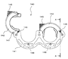
- FIG. 5 is a perspective view of a clamper in a state where a syringe receiver is removed in FIG. 4. It is a front view of the clamper shown in FIG.
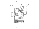
- FIG. 7 is a sectional view taken along line AA in FIG. 6. It is a block diagram which shows the electrical structure of a chemical injection device.
- FIG. 2 It is a perspective view explaining the mounting
- a fluoroscopic imaging system 1000 having a CT angio apparatus 300 that is a fluoroscopic imaging apparatus and a chemical injection system.
- the chemical solution injection system includes a chemical solution injection device 100 and a syringe assembly 200 (see FIG. 3) attached to the chemical solution injection device 100, which is not shown in FIG.
- the CT angiography apparatus 300 includes an imaging unit 301 that performs an imaging operation and an imaging control unit 302 that controls the operation of the imaging unit 301, which are connected via a communication network.
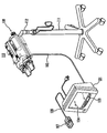
- the chemical injection device 100 includes an injection head 110 that is pivotably attached to an upper portion of a stand 111 via an arm 112, and an injection control that is electrically connected to the injection head 110 via a cable 102.
- the injection control unit 101 includes a main operation panel 103, a touch panel 104 serving as a display unit and an input unit, and a hand unit 107 which is an auxiliary input unit electrically connected to the main body of the injection control unit 101 through a cable 108.
- the injection head 110 is detachably mounted with two sets of syringe assemblies 200 (in FIG. 3, only one set of syringe assemblies 200 is shown for simplicity).
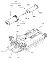
- the syringe assembly 200 includes a syringe 220 and a protective cover 270 into which the syringe 220 is inserted.
- the syringe 220 is a syringe 220 generally referred to as a rodless syringe, and includes a cylinder 221 having a flange 221a formed at the end and a nozzle portion 221b formed at the tip, and a piston 222 inserted into the cylinder 221 so as to be capable of moving forward and backward. And have.
- the piston 222 is integrally formed with an engagement protrusion (not shown) that engages with a piston drive mechanism 130 described later at the end thereof.
- the filled chemical liquid is pushed out from the syringe 220 through the nozzle part 221b.
- an extension tube (not shown) having an injection needle or catheter connected to the tip is connected to the nozzle portion 221b, the injection needle or catheter is punctured or inserted into the blood vessel of the subject, and the liquid medicine filled in the syringe 220 is supplied to the subject.
- the chemical solution filled in the syringe 220 include a contrast agent, physiological saline, and an anticancer agent.
- one syringe 220 can be filled with a contrast agent, and the other can be filled with physiological saline. .
- both syringes can be filled with an anticancer agent.
- a highly viscous chemical solution such as a contrast medium
- a contrast agent used in an angio apparatus that captures a blood vessel image of a subject has a high viscosity.
- the internal pressure of the cylinder 221 becomes very high. This high internal pressure causes the cylinder 221 to expand, which may cause various problems in injecting the chemical liquid.
- the protective cover 270 suppresses expansion due to an increase in the internal pressure of the cylinder 221 at the time of injecting the chemical solution, and is a component configured in a cylindrical shape so that the outer peripheral surface of the cylinder 221 is inserted with almost no gap.
- the protective cover 270 is formed with a thickness having mechanical strength that can sufficiently withstand the internal pressure acting on the cylinder 221 during the injection of the chemical liquid.
- An opening is formed at the tip of the protective cover 270, and the cylinder 221 is held by the protective cover 270 with the nozzle portion 221b protruding from the opening.
- a cover flange 271 having a recess for receiving the flange 221a of the cylinder 221 is formed at the end of the protective cover 270.
- the injection head 110 has two piston drive mechanisms 130 that are driven to move the pistons 222 of the two syringe assemblies 200 attached to each other in a forward / backward manner, corresponding to positions where the syringe assemblies 200 are attached.
- the piston drive mechanism 130 includes a piston holding mechanism that holds an engagement protrusion formed at the end of the piston 222, and a rod member that is connected to a drive source such as a motor that moves the piston holding mechanism forward and backward.
- the piston holding mechanism is located at the tip of the rod member and can be designed, for example, as a hook configured to engage the engaging protrusion of the piston 222 and thereby hold the engaging protrusion.
- the syringe assembly 200 attached to the injection head 110 can inject the liquid medicine filled in the syringe 220 into the subject separately or simultaneously by the piston 222 being advanced by the piston drive mechanism 130.
- the piston drive mechanism 130 a known mechanism generally used in this type of injection device can be employed.
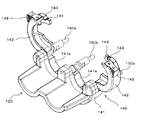
- the tip of the injection head 110 is provided with a syringe receiver 120 and a clamper 140 that constitute a syringe mounting portion on which the syringe assembly 200 is placed.
- the clamper 140 is configured to individually hold the cover flange 271 of each syringe assembly 200.
- the syringe receiver 120 is located on the tip side of the clamper 140 and has two recesses 121 that individually receive the outer peripheral surfaces of the cylinder assemblies 200.
- Each cylinder assembly 200 is positioned in the recess 121 with the nozzle portion 221b facing the tip, and is fixed to the injection head 110 by the cover flange 271 being held by the clamper 140.
- FIGS. 5 and 6 show the syringe receiver 120 removed.
- the clamper 140 includes three shafts 150a, 150b, and 150c, a base member 141, and two flange pressing members 142 that are arranged in parallel at intervals.
- the shafts 150a to 150c also serve as a part of the frame structure of the injection head 110, and support the clamper 140 at the tip.
- the interval between the shafts 150a to 150c is larger than the diameter of the cover flange 271 that is a part of the syringe assembly 200 held by the clamper 140.
- the base member 141 has two flange receiving recesses 141a located between the shafts 150a to 150c.
- the flange receiving recess 141a is formed in an arc shape that is substantially equal to the outer shape of the portion that the flange receiving recess 141a of the cover flange 271 receives so that a part of the cover flange 271 can be received.
- the two flange pressing members 142 receive a remaining portion of the cover flange 271 that is not received by the flange receiving recess 141a and are combined with each flange receiving recess 141a so as to surround the cover flange 271 over the entire circumference. It is an arc-shaped part. Therefore, the inner surface of the flange pressing member 142 has an arcuate groove that is substantially the same as the outer shape of the portion that the flange pressing member 142 of the cover flange 271 receives, like the flange receiving recess 141a.
- Each flange pressing member 142 is rotatably supported at one end by the outer shafts 150a and 150c so as to open and close with respect to the flange receiving recess 141a, and the cover flange 271 can be attached and detached.
- the closed position where 271 is held can be taken.
- the flange pressing member 142 engages with the central shaft 150b to fix the flange pressing member 142 in the closed position at the free end that is opposite to the ends supported by the shafts 150a and 150c.
- An engagement structure is provided.
- the engagement structure may be any structure as long as the flange pressing member 142 can be engaged and released.
- the flange pressing member 142 has a concave portion 143 and a ball plunger 144 arranged on the outer surface of the free end portion.
- the recessed portion 143 is formed in a shape that hangs on the outer peripheral surface of the central shaft 150b when the flange pressing member 142 is in the closed position.
- the ball plunger 144 includes a ball, a casing that accommodates a part of the ball so that the ball can protrude, and a spring that biases the ball in a direction in which the ball protrudes from the casing. It is embedded in the flange pressing member 142 so as to protrude.
- the position of the ball plunger 144 is such that the ball of the ball plunger 144 contacts the shaft 150b and is pushed into the casing while the flange pressing member 142 rotates from the open position to the closed position. It is preferable that the recess 143 is engaged with the shaft 150b immediately after passing. By doing so, the flange pressing member 142 can be favorably held in the closed position. In addition, since the click feeling is obtained when the ball passes through the shaft 150b, the operator can easily recognize that the flange pressing member 142 has reached the closed position.
- the ball plunger 144 as the engagement structure, when the engagement of the flange pressing member 142 in the closed position with the shaft 150b is released, the flange pressing member 142 is simply rotated toward the release position. It's okay. Therefore, in this embodiment, the flange pressing member 142 has a knob 145 at the free end so that the flange pressing member 142 can be easily rotated.
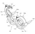
- the base member 141 detects the presence / absence or position of an object in a non-contact manner at a position corresponding to each flange pressing member 142.
- the proximity sensor 146 is provided as a second detector.
- Each flange pressing member 142 is provided with a detection object 147 detected by the corresponding proximity sensor 146 when each flange pressing member 142 is in the closed position.
- the proximity sensor 146 and the detected object 147 are disposed near the rotation center of the flange pressing member 142 and at positions facing each other when the flange pressing member 142 is in the closed position.
- the proximity sensor 146 detects the detected object 147 when the distance to the detected object 147 is equal to or less than a predetermined distance. Therefore, when the flange pressing member 142 is not in the closed position, the distance between the proximity sensor 146 and the detected object 147 is larger than a predetermined distance, but when the flange pressing member 142 is in the closed position, the proximity sensor 146 and the detected object are not detected.
- the proximity sensor 146 and the object to be detected 147 are arranged so that the distance to the 147 is a predetermined distance or less.
- FIG. 7 is a cross-sectional view taken along the line AA of FIG.
- the base member 141 and the flange pressing member 142 have through-holes 141b and 142b parallel to the rotation shaft of the flange pressing member 142, respectively, and are collinear when the flange pressing member 142 is in the closed position. It is formed in the position to line up.
- the proximity sensor 146 is inserted into the through hole 141b of the base member 141 and fixed.
- the detected object 147 is inserted and fixed in the through hole 142b of the flange pressing member 142.
- the distance between the two decreases as the flange pressing member 142 is rotated from the open position toward the closing position, and the flange pressing member 142 is closed.
- Minimum when in position. Therefore, the position of the proximity sensor 146 in the through hole 141b is larger than the predetermined distance when the flange pressing member 142 is not in the closed position, but is less than the predetermined distance when the flange pressing member 142 is in the closed position.
- proximity sensors detect the presence and position of an object using magnetism as a detection medium.
- the types of magnetism detected by the proximity sensor include a DC static magnetic field and an AC magnetic field, both of which can be used in the present invention.
- a magnet or an electromagnet is used as the object to be detected 147
- a semiconductor magnetic sensor such as a magnetoresistive element or a Hall element, a flux gate type sensor, MR (Magneto-) as the proximity sensor 146.
- MR Magnetic-
- a ferromagnetic magnetic sensor such as a Resistive element or an MI (Magneto-Impedance) element can be used.
- the proximity sensor 146 that detects a DC static magnetic field uses a magnet or an electromagnet as the detected object 147.
- the magnet When attaching the magnet to the flange pressing member 142, there is a concern that the magnet may be attached with the polarity reversed.
- the electromagnet requires an operation circuit for the electromagnet separately from the detection circuit for the proximity sensor 147.
- a proximity sensor 146 using an AC magnetic field as a detection medium which can use a metal as the object to be detected 147 and thereby does not cause the above-described problem.
- the proximity sensor 146 using an AC magnetic field as a detection medium has a shorter distance at which the detection object 147 can be detected than a proximity sensor using a DC static magnetic field as a detection medium such as a Hall element, so the flange pressing member 142 is closed. The position can be detected more accurately.
- the proximity sensor 146 using an AC magnetic field as a detection medium has a coil.
- a constant AC current is supplied from an AC power source to the coil and an AC magnetic field is applied to a metal (detected object 147)
- an eddy current is generated in the metal.
- the eddy current generated in the metal generates a magnetic field, and an induced voltage is generated in the coil.
- the impedance of the coil which is the ratio of the voltage generated in the coil to the current passed through the coil, changes, and the proximity sensor 146 uses this change in impedance to detect the metal. .
- one coil has a function as an excitation coil that applies an alternating magnetic field to the detected object 147 and a function as a detection coil that detects an eddy current magnetic field generated from the detected object 147. It can be roughly divided into a single coil type and a multi-coil type having a plurality of coils.
- the types of the single-coil proximity sensor 146 include a high-frequency oscillation type and a filter type.
- the high-frequency oscillation type proximity sensor 146 incorporates a detection coil in a part of the oscillation circuit, and detects a change in oscillation amplitude or oscillation frequency in accordance with the impedance change.
- the filter-type proximity sensor 146 uses the fact that the detection coil is incorporated in a part of the LC or LR filter circuit, and the filter characteristics change due to the impedance change of the detection coil.
- the types of the multi-coil proximity sensor 146 include a double coil type, a differential coil type, and a hawk coil type.
- the double-coil proximity sensor 146 uses two coils having the same structure, one of which is used as a detection coil and close to the detected object 147, and the other is used as a reference coil so as not to be affected by the detected object 147. . If the two coils are excited under the same conditions and the difference in induced voltage is compared, the detection coil is affected by the approach of the detected object 147. Therefore, the difference between the two induced voltages is due to the approach of the detected object 147. It means that.
- a method of the detection circuit a method is generally used in which an impedance bridge is constituted by two coils, and this is excited by a fixed oscillator to detect the amplitude of the unbalanced voltage and the phase with respect to the excitation current. Alternatively, there is a method in which the unbalanced voltage obtained from the bridge circuit is amplified and fed back to the excitation side of the bridge circuit to oscillate the circuit and detect its amplitude.
- the detection coils are arranged at symmetrical positions on both sides of the exciting coil, and the terminals of the detection coil are connected in series reverse polarity to serve as detection output terminals. Since the exciting magnetic flux generates an induced voltage equal to the detection coil, the induced voltage due to the exciting magnetic flux is canceled, and only the induced voltage due to the magnetic flux generated by the eddy current can be taken out as in the double coil type. After that, similarly to the double coil type, the amplitude and phase of the output voltage of the detection coil terminal may be detected, or the voltage of the detection coil terminal may be amplified and fed back to the excitation coil to oscillate.
- the hawk coil type proximity sensor 146 has an excitation coil and a detection coil arranged to face each other to create a magnetic coupling, and an amplitude or phase change of an induced voltage generated in the detection coil by inserting a detected object 147 therebetween. Is detected.
- the proximity sensor 146 that can detect metal in a non-contact manner using an AC magnetic field as a detection medium has been described above. Any of these can be used in the present invention, and among them, a high-frequency oscillation type single-coil proximity sensor such as E2E-X1C1 manufactured by OMRON Corporation can be preferably used.
- the entire object 147 may be made of metal, or a part thereof may be made of metal.
- the size and shape of the object to be detected 147 can be arbitrarily set as long as the opening / closing operation of the flange pressing member 142 is not hindered.
- the detected object 147 may be a ball plunger.
- a ball plunger similar to the ball plunger 144 (see FIG. 5) provided in the flange pressing member 142 in order to fix the flange pressing member 142 in the closed position can be used.
- the ball plunger When a ball plunger is used as the object to be detected 147, the ball plunger is fixed to the flange pressing member 142 by projecting a part of the ball from the surface of the flange pressing member 142 facing the base member 141. A part of the protruded ball engages with the through hole 141b that holds the proximity sensor 146 when the flange pressing member 142 is in the closed position. Thereby, the detected object 147 can have an auxiliary function of the ball plunger 144 that locks the flange pressing member 142 in the closed position.
- the proximity sensor 146 and the object 147 to be detected are fixed in the through holes 141b and 142b so as not to be displaced. Therefore, the proximity sensor 146 and the detected object 147 can be press-fitted into the through holes 141b and 142b. Alternatively, the proximity sensor 146 may be screwed. Thereby, the position adjustment of the proximity sensor 146 in the through hole 141b and the removal for replacement of the proximity sensor 146 can be easily performed.
- the through hole 141b is preferably filled with resin. Thereby, the waterproof property of the proximity sensor 146 is enhanced, and the possibility that the proximity sensor 146 may fail when a chemical solution or the like adheres to the clamper 140 can be reduced.
- the ball plunger 144 is used for the engagement structure for locking the flange pressing member 142 in the closed position.
- the proximity sensor 147 is connected to the flange pressing member 142 in the closed position.
- it can also be placed on the portion of the base member 141 that faces the ball plunger 144. By doing so, the ball plunger 144 constituting the engagement structure can be used as an object to be detected, and the construction of the clamper 140 can be simplified.
- each syringe assembly 200 is provided with a detection object 272 that can be detected by the proximity sensor 148 in a non-contact manner.
- the cover flange 271 of the protective cover 270 has a convex portion 271 a protruding further in the radial direction from the cover flange 271 in a part in the circumferential direction, and the object 272 to be detected is It is installed on the convex portion 271a.
- each flange receiving recess 141a of the clamper 140 is formed with a groove 141c.
- the groove portion 141c receives the convex portion 271a of the protective cover 270 when the syringe assembly 200 is attached to the clamper 140, thereby preventing the syringe assembly 200 from rotating in the circumferential direction.
- the proximity sensor 148 is disposed at a position where the detected object 272 is detected when the convex portion 271a of the protective cover 270 is normally received in the groove portion 141c of the clamper 140.
- the usable proximity sensor 148 and the detected object 272 are the same as the proximity sensor 146 and the detected object 147 for detecting that the flange pressing member 142 is in the closed position.
- the proximity sensor 148 that detects that the convex portion 271a of the protective cover 270 is normally received in the groove portion 141c of the clamper 140 is configured to detect the types of the protective cover 270 corresponding to various sizes of the syringe 220. May be.
- a proximity sensor such as a semiconductor magnetic sensor using a DC static magnetic field as a detection medium can detect a plurality of patterns from a combination of N and S poles. Like the proximity sensor, it can be preferably used.
- the attachment of the proximity sensor 148 to the clamper 140 and the attachment of the detected object 272 to the protective cover 270 are also performed on each member in the same manner as the proximity sensor 146 and the detected object 147 for detecting opening and closing of the flange pressing member 142. This can be done by forming holes and fixing the proximity sensor 148 and the object 272 to be detected in the holes, respectively. These fixing methods may be the same as the fixing method of the proximity sensor 146 and the detected object 147.
- FIG. 8 shows a block diagram of the main electrical configuration of the chemical injection device of this embodiment.
- Each block shown in FIG. 8 exists as at least a part of the configuration described in FIGS. 1 to 7 or a combination of at least a part thereof, and may be configured as hardware or configured as a logic circuit. May be.
- the injection control unit 101 includes a control unit 161, an input unit 162, a display unit 163, and an interface (I / F) 164.
- the input unit 162 corresponds to the main operation panel 103 and the touch panel 104 shown in FIG. 2, and accepts input of data necessary for determining various settings of the chemical solution injection device 100 and chemical injection conditions by the operator.
- the display unit 163 corresponds to the touch panel 104 shown in FIG. 2, and displays a screen representing the operating state of the chemical solution injector 100 and a data input screen. As described above, in this embodiment, the touch panel 104 has both a function as a part of the input unit 162 and a function of the display unit 163.
- the control unit 161 calculates a chemical injection condition based on an input from the input unit 162, displays necessary information on the display unit 163, or drives the piston driving mechanism 130 according to the calculated injection condition.
- the overall operation of the chemical liquid injector 100 is controlled.
- the control unit 161 is connected to the proximity sensors 146 and 148 and the piston drive mechanism 130 of the injection head 110, and necessary information is based on signals from the proximity sensors 146 and 148 and other sensors (not shown). Is displayed on the display unit 163, or the operation of the piston drive mechanism 130 is controlled.
- the control unit 161 can be configured by a computer unit including a CPU, a RAM, and a ROM.
- a control signal for the operation of the piston drive mechanism 130 emitted from the control unit 161 and a part of the injection condition of the chemical solution calculated by the control unit 161 are sent to the angio device 300 via the interface 164, thereby The chemical injection device 100 and the angio device 300 can be interlocked.
- the operator turns on the power of the chemical liquid injector 100 and then attaches the syringe assembly 200 filled with the chemical liquid to be injected to the subject to the injection head 110.
- a chemical solution container (not shown) is connected to the nozzle portion 221b via a tube or a suction tube, and the piston 222 is retracted in that state.
- the syringe assembly 200 may be filled with a chemical solution, and the syringe assembly 200 filled with the chemical solution may be attached to the injection head.
- the former type is referred to as a prefilled type
- the latter type is also referred to as a post-filling type.
- the cover flange 271 is positioned on the flange receiving recess 141a (see FIG. 5) with the flange pressing member 142 in the open position.
- the syringe assembly 200 is mounted on the syringe receiver 120 so that the convex part 271a (refer FIG. 3) is inserted in the groove
- the position of the piston 222 in the cylinder 221 is set to a predetermined position.
- the chemical injection device 100 performs an initialization operation of the piston holding mechanism 130 when the power is turned on.
- the piston holding mechanism is in a state where the syringe assembly 200 is placed on the syringe receiver 120.
- the piston drive mechanism is operated so as to be in the initial position for engaging with the engaging protrusion of the piston 222.
- the initial position of the piston holding mechanism is the end of the moving range of the piston holding mechanism, and the position of the piston holding mechanism can be detected by a sensor (not shown).
- any sensor can be used as this sensor, but an optical sensor such as a transmissive photosensor (photointerrupter) or a reflective photosensor can be preferably used.
- the transmissive photosensor may be used as a linear encoder or a rotary encoder in combination with a slit plate supported so as to move linearly or rotate in conjunction with a piston holding mechanism.
- the plate plate In combination with a plate member supported so as to move linearly in conjunction with the piston holding mechanism, the plate plate is positioned between the light emitting element and the light receiving element of the transmissive photosensor when the piston holding mechanism is in the initial position.
- it may be used as a limit sensor configured to block light from the light emitting element.
- a reflective photosensor basically the same as the above as an encoder except that the slit plate and the plate member block the light from the light emitting element or reflect it toward the light receiving element. It can be used as a limit sensor. Furthermore, it can also be set as the structure provided with both the encoder and the limit sensor using the some optical sensor.
- the piston holding mechanism is waiting at the initial position by the initialization operation of the piston driving mechanism 130. Therefore, when the syringe assembly 200 is placed on the syringe receiver 120, at the same time, the piston holding mechanism is engaged with the engagement protrusion of the piston 222.
- the engagement between the piston holding mechanism and the engagement protrusion of the piston 222 can be detected by a sensor (not shown).
- the amount of chemical liquid injected into the subject and the amount of chemical liquid sucked into the syringe 220 are generally based on the assumption that the movement amount of the piston 222 is equal to the movement amount of the piston holding mechanism. Is calculated based on If the engagement protrusion of the piston 222 and the piston holding mechanism are separated in the initial state, the piston 222 does not move until the piston holding mechanism comes into contact with the engagement protrusion, and the amount of movement of both does not move. The amount cannot be calculated.
- the piston 222 may be pushed more than necessary, and the syringe 220 may be damaged. Accordingly, the engagement between the piston holding mechanism and the engagement protrusion of the piston 222 can be detected, and the detection result is indicated to the operator by display or voice, or the next operation is performed until it is detected that the engagement is detected. It is possible to prevent the above-mentioned problems by preventing the process from proceeding to the above.
- the engagement between the piston holding mechanism and the engagement protrusion of the piston 222 can be detected by, for example, a strain sensor, an infrared sensor, a color recognition CCD sensor, a color identification sensor, and a mechanical switch.
- the operator rotates the flange pressing member 142 to engage the engagement structure with the central shaft 150b, as shown in FIG.
- the member 142 is locked in the closed position.
- the cover flange 271 is fixed to the syringe holder 140 and the syringe assembly 200 is attached to the injection head 110.
- An injection needle or catheter is connected to the syringe assembly 200 via an extension tube, and the injection needle or catheter is punctured or inserted into the blood vessel of the subject, so that the drug solution filled in the syringe assembly 200 is supplied to the subject. You will be ready to inject.
- the injection needle or catheter may be punctured or inserted before or after the syringe assembly 200 is mounted on the injection head 110, but in the case of the empty syringe assembly 200, the syringe assembly is inserted. After 200 is filled with the chemical solution.
- a branch tube (not shown) equipped with an appropriate valve device, etc. Can also puncture or insert an injection needle or catheter prior to filling the syringe assembly 200 with a drug solution.
- the proximity sensor 148 detects the object 272 to be detected of the syringe assembly 200, and accordingly, the syringe assembly 200 is mounted on the injection head 110. Detected. Further, when the flange pressing member 142 is locked at the closed position, the proximity sensor 146 detects the detected object 147 of the flange pressing member 142, thereby detecting that the flange pressing member 142 is locked at the closed position.
- the proximity sensor 146 actually detects that the flange pressing member 142 is in the closed position and does not detect that the flange pressing member 142 is locked in the closed position. However, since the flange pressing member 142 reaches the closed position, it is locked in that position by the engaging structure, so that the proximity sensor 146 substantially detects that the flange pressing member 142 is locked in the closed position. It's okay.
- the flange pressing member 142 holds the syringe assembly 200 by receiving the cover flange 271 over the entire circumference in cooperation with the flange receiving recess 141a. Therefore, in a state where the flange pressing member 142 is locked at the closed position, the syringe assembly 200 is fixed to the clamper 140 and attached to the injection head 110 at the correct position and posture.
- the proximity sensor that detects that the syringe assembly 200 is mounted on the clamper 140 by configuring the clamper 140 to hold the syringe assembly 200 by surrounding the entire circumference of the cover flange 271.
- Two sensors 148 and a proximity sensor 146 that detects that the clamper 140 is locked in the closed position can detect that the syringe assembly 200 is mounted on the injection head 110 in the correct posture.
- the control unit 161 When the syringe assembly 200 is mounted on the injection head 110 as described above, detection signals are sent from the proximity sensors 146 and 148 to the control unit 161.
- the controller 161 receives the detection signals from the proximity sensors 146 and 148, whether the attached syringe assembly 200 is a prefilled type or a post-filling type, from another viewpoint, the control unit 161 is a syringe assembly 200 filled with a chemical solution.
- the following processing is executed. If the sensor is configured to detect the initial position of the piston holding mechanism, in addition to the detection signals from the proximity sensors 146 and 148, a sensor that detects that the piston holding mechanism is at the initial position. Is output to the control unit 161, and the control unit 161 receives these three detection signals, whereby the control unit 161 executes the following processing.
- the type of the attached syringe assembly 200 can be determined by the operator inputting, for example, the type of the attached syringe assembly 200 through the input unit 162 and the control unit 161 determining from the input result.
- the syringe assembly 200 includes an RFID chip (not shown) and the chemical injection device 100 includes an RFID reader (not shown), and the control unit 161 is based on the reading result of the RFID chip by the RFID reader.
- the information recorded on the RFID chip includes at least information on whether the syringe is a prefilled type or a post-filling type.
- the syringe assembly 200 is filled with the chemical solution by connecting the tip of the syringe assembly 200 to a chemical solution container (not shown), and in this state, the piston 222 is retracted by the piston drive mechanism 130, and the chemical solution in the chemical solution container is transferred to the syringe assembly 200. This can be done by sucking in. Prior to this suction operation, the controller 161 causes the piston drive mechanism 130 to perform the suction preparation operation described below.
- control unit 161 operates the piston drive mechanism 130 so that the piston 222 is pushed toward the tip of the syringe assembly 200 and is positioned at the forward end position that is the most advanced position inside the cylinder 221. All the air in the syringe 220 is pushed out.
- the injection needle or catheter is not punctured or inserted into the subject, or the path from the syringe 220 to the injection needle or catheter is blocked, and the syringe 220 and the subject's blood vessel are in fluid communication. Absent.
- the forward end position can be the forward end position of the piston holding mechanism, and the forward end position of the piston holding mechanism can be detected by a sensor similar to the sensor that detects the initial position of the piston holding mechanism.
- a sensor similar to the sensor that detects the initial position of the piston holding mechanism Good. That is, when the sensor for detecting the initial position of the piston holding mechanism is a rotary encoder or a linear encoder, this encoder can also be used as a sensor for detecting the forward end position of the piston holding mechanism.
- the sensor that detects the initial position of the piston holding mechanism is a limit sensor and has a plate member that moves linearly in conjunction with the piston holding mechanism, a transmission type or reflective type photo sensor is provided separately from this limit sensor.
- the plate member When the piston holding mechanism is at the forward end position, the plate member operates with a transmissive or reflective photosensor (if the photosensor is transmissive, the plate member blocks light from the light emitting element and When the sensor is a reflection type, the plate member is arranged so that the light from the light emitting element is reflected toward the light receiving element.
- a limit sensor may be further added so that the forward end position of the piston holding mechanism can also be detected by this limit sensor.
- the control unit 161 operates the piston drive mechanism 130 so that the piston 222 is automatically positioned at the foremost inside of the cylinder 221, for example, Even if the operator misunderstands the syringe 220 that has not been filled with the chemical solution as if it had been filled with the chemical solution and causes the chemical injection device to execute the chemical injection operation, the piston 222 moves forward further. Can not do it. Therefore, it is possible to reliably prevent a medical accident that air is injected into the blood vessel of the subject.
- the control unit 161 can also display information indicating that the syringe assembly 200 is correctly mounted, that is, that the mounting of the syringe assembly 200 is completed, on the display unit 163 together with the above-described suction preparation operation. Thereby, the operator can confirm easily that mounting
- display of information indicating that the attachment of the syringe assembly 200 is completed can be executed alone.
- the information displayed on the display unit 163 may be a message by text or information represented by a symbol.
- the display unit 163 includes a light emitting lamp (not shown), and lighting the light emitting lamp may indicate that the mounting of the syringe assembly 200 is completed.
- the light emitting lamp may be arranged in the injection head 110.
- a speaker (not shown) may be further added to the chemical injection device 100, and from this speaker, the fact that the syringe assembly 200 is correctly attached may be notified by voice, or the display and voice may be combined.
- control unit 161 When the control unit 161 receives a detection signal only from the proximity sensor 148 that detects the detection object 272 of the syringe assembly 200, the control unit 161 determines that the syringe assembly 200 is not mounted, and displays that fact. 163 is displayed to alert the operator. Alternatively, when the control unit 161 receives a detection signal only from the proximity sensor 146 that detects the detected object 147 of the flange pressing member 142, the control unit 161 determines that the syringe assembly 200 is not normally held, This is displayed on the display unit 163 to alert the operator.
- the operator confirms that the syringe assembly 200 has been correctly attached, and when the fact is input via the input unit 162, the control unit 161 starts an operation for injecting the chemical solution. More specifically, the control unit 161 causes the display unit 163 to display an operation mode selection screen and / or an injection condition setting screen of the chemical solution injection device 100 and allows the input unit 162 to select an operation mode and / or Or, an input operation for setting injection conditions is made possible.
- the operation for injecting the chemical liquid includes not only an operation directly related to the chemical liquid injection but also an operation of sucking the chemical liquid into the syringe 220 as a pre-stage of the chemical liquid injection, and the operation is performed when the syringe assembly 200 is a post-fill type.
- the mode includes a suction mode. Therefore, when the attached syringe assembly 200 is a post-filling type (empty syringe), the operator confirms that the syringe 220 and the blood vessel of the subject are not in fluid communication with each other, and then performs a suction operation on the liquid injector 100. After that, the injection operation to the subject is executed.
- a post-filling type empty syringe
- the control unit 161 When the operation mode selection screen and / or the injection condition setting screen are displayed on the display unit 163, the operator selects an operation mode or inputs data as necessary. Based on this input, the control unit 161 performs necessary processing and controls the piston drive mechanism 130 to inject a drug solution from the syringe assembly 200 to the subject. Since these operations may be the same as those of a normal chemical solution injector, detailed description thereof is omitted.
- the chemical solution is kept without being attached or not being correctly attached by preventing the control unit 161 from proceeding to the next step.
- the injection operation can be prevented from being executed. If the chemical solution injection operation is performed without the syringe assembly 200 being correctly attached, an accident such as the syringe assembly 200 being detached during the chemical solution injection may occur. Therefore, by making it possible to detect that the syringe assembly 200 is correctly attached as in this embodiment, such an accident can be prevented.
- the cover flange 271 can receive a force on the entire circumference when the chemical solution is injected.
- the force received by the cover flange 271 during the injection of the chemical liquid is distributed over the entire circumference of the cover flange 271, and even when the chemical liquid is injected at a high pressure, the possibility that the cover flange 271 is damaged is extremely low.
- the output from the sensor can be changed according to the type of metal to be detected. If a different kind of metal is used for each detection object 272, it is possible to determine not only that the syringe assembly 200 is mounted but also the type of the syringe assembly 200 that is mounted.
- the types of the syringe assembly 200 are classified by, for example, the concentration of the active ingredient of the filled chemical solution (typically, the iodine concentration in the contrast medium), the volume and size of the syringe 220, and combinations thereof. Can do.
- the proximity sensor 148 is used as the first detector that detects that the syringe assembly 200 is placed on the placement unit.
- a syringe is used. No proximity sensor is required to detect the assembly.
- Some recent chemical injection systems include an RFID chip in a syringe and an RFID reader that acquires data from the RFID chip in a chemical injection device.
- Various data such as data relating to a filled chemical solution and data relating to a subject are recorded on the RFID chip as necessary.
- the chemical injection device can use the data acquired from the RFID chip to calculate the chemical injection conditions, record the use history of the syringe, and record the chemical injection history of the subject.
- an RFID reader is installed at a position where data can be acquired from the RFID chip with the syringe attached. Therefore, if the RFID reader can acquire data from the RFID chip, this means that the syringe is attached to the chemical solution injector. That is, the RFID reader can also serve as the first detector, and in this case, the proximity sensor 148 is unnecessary.
- the RFID reader has a wider detectable range than the proximity sensor, and may detect the syringe assembly 200 even if there is a positional deviation when the cover flange 271 is placed on the flange receiving recess 141a of the clamper 140.
- the detection of the cylinder assembly 200 does not require such high positional accuracy. Misalignment is not a problem.
- the first detector is not limited to the proximity sensor 148 and the RFID reader described above, and any detector can be used, and the position of the first detector is also arbitrary.
- the RFID chip may be mounted on the cylinder 221, may be mounted on the protective cover 270, or may be mounted on both. Good.
- the RFID reader is installed at a position where the RFID chip can be read when the syringe assembly is mounted on the injection head according to the position of the RFID chip.
- the protective cover 270 is not essential in the present invention.
- a syringe assembly that is filled with a chemical solution having a viscosity that is not so high is often not equipped with a protective cover.
- the clamper is configured to hold a flange formed at the end of the cylinder.
- the RFID chip is mounted on the cylinder.
- a weight sensor is further provided in a syringe mounting part, and it is mounted in the syringe mounting part by this weight sensor. It may be possible to detect whether the syringe assembly is filled with a chemical solution. In this case, it is preferable that a warning is displayed and / or sounded to the operator if the syringe assembly is not filled with a chemical solution.
Landscapes
- Health & Medical Sciences (AREA)
- Vascular Medicine (AREA)
- Engineering & Computer Science (AREA)
- Anesthesiology (AREA)
- Biomedical Technology (AREA)
- Heart & Thoracic Surgery (AREA)
- Hematology (AREA)
- Life Sciences & Earth Sciences (AREA)
- Animal Behavior & Ethology (AREA)
- General Health & Medical Sciences (AREA)
- Public Health (AREA)
- Veterinary Medicine (AREA)
- Infusion, Injection, And Reservoir Apparatuses (AREA)
Priority Applications (1)
| Application Number | Priority Date | Filing Date | Title |
|---|---|---|---|
| JP2011553883A JP5985188B2 (ja) | 2010-02-12 | 2011-02-10 | 薬液注入装置および薬液注入システム |
Applications Claiming Priority (2)
| Application Number | Priority Date | Filing Date | Title |
|---|---|---|---|
| JP2010029183 | 2010-02-12 | ||
| JP2010-029183 | 2010-12-07 |
Publications (1)
| Publication Number | Publication Date |
|---|---|
| WO2011099551A1 true WO2011099551A1 (ja) | 2011-08-18 |
Family
ID=44367821
Family Applications (1)
| Application Number | Title | Priority Date | Filing Date |
|---|---|---|---|
| PCT/JP2011/052850 Ceased WO2011099551A1 (ja) | 2010-02-12 | 2011-02-10 | 薬液注入装置および薬液注入システム |
Country Status (2)
| Country | Link |
|---|---|
| JP (4) | JP5985188B2 (https=) |
| WO (1) | WO2011099551A1 (https=) |
Cited By (8)
| Publication number | Priority date | Publication date | Assignee | Title |
|---|---|---|---|---|
| JP2016504129A (ja) * | 2013-01-29 | 2016-02-12 | サノフィ−アベンティス・ドイチュラント・ゲゼルシャフト・ミット・ベシュレンクテル・ハフツング | プランジャの位置を検出する装置 |
| CN109195713A (zh) * | 2016-03-16 | 2019-01-11 | 汉高股份有限及两合公司 | 用于一种和两种组分料箔和料盒的电池供能的分配器 |
| CN109689129A (zh) * | 2016-09-16 | 2019-04-26 | 拜耳医药保健有限公司 | 具有针筒保持元件的压力护套 |
| WO2020090878A1 (ja) * | 2018-10-31 | 2020-05-07 | 株式会社サーキュラス | 薬液容器アセンブリのクランパ、該クランパを有する薬液注入装置および薬液注入システム |
| CN113274590A (zh) * | 2021-07-23 | 2021-08-20 | 科睿驰(深圳)医疗科技发展有限公司 | 用于医疗设备的连接装置 |
| WO2021194359A1 (en) * | 2020-03-27 | 2021-09-30 | Robert Lauwrence Ward | Syringe pump |
| CN113663161A (zh) * | 2021-08-11 | 2021-11-19 | 深圳圣诺医疗设备股份有限公司 | 一种注射泵的针筒规格识别校准系统和方法 |
| CN113713202A (zh) * | 2021-09-13 | 2021-11-30 | 临床支持有限公司 | 高压造影剂注射系统 |
Families Citing this family (6)
| Publication number | Priority date | Publication date | Assignee | Title |
|---|---|---|---|---|
| US10653829B2 (en) * | 2016-08-01 | 2020-05-19 | West Pharma. Services IL, Ltd. | Automatic injector having door block until proper cartridge insertion |
| US11730892B2 (en) | 2016-08-01 | 2023-08-22 | West Pharma. Services IL, Ltd. | Partial door closure prevention spring |
| CN106823070B (zh) * | 2017-03-21 | 2023-03-07 | 深圳安特医疗股份有限公司 | 针筒识别装置、高压注射器及其控制方法 |
| EP3630226B1 (en) | 2017-05-30 | 2025-10-22 | West Pharma. Services Il, Ltd. | Modular drive train for wearable injector |
| MX2021008066A (es) | 2019-01-07 | 2021-08-05 | Nippon Steel Corp | Lamina de acero y metodo de fabricacion de la misma. |
| US12465268B2 (en) | 2020-10-12 | 2025-11-11 | Biosense Webster (Israel) Ltd. | Guiding sheath with distal tip locator |
Citations (5)
| Publication number | Priority date | Publication date | Assignee | Title |
|---|---|---|---|---|
| JP2004305361A (ja) * | 2003-04-04 | 2004-11-04 | Nemoto Kyorindo:Kk | 薬液注入装置 |
| WO2006006643A1 (ja) * | 2004-07-14 | 2006-01-19 | Nemoto Kyorindo Co., Ltd. | 薬液注入システム |
| WO2006068171A1 (ja) * | 2004-12-24 | 2006-06-29 | Nemoto Kyorindo Co., Ltd. | 薬液注入装置 |
| WO2006109778A1 (ja) * | 2005-04-11 | 2006-10-19 | Nemoto Kyorindo Co., Ltd. | 薬液注入システム |
| JP2008292457A (ja) * | 2007-04-22 | 2008-12-04 | Azuma Systems:Kk | 検出装置及び検出方法 |
Family Cites Families (12)
| Publication number | Priority date | Publication date | Assignee | Title |
|---|---|---|---|---|
| JPH1010104A (ja) * | 1996-06-26 | 1998-01-16 | Shimadzu Corp | シリンジ計量器 |
| US5865805A (en) * | 1997-07-16 | 1999-02-02 | Liebel-Flarsheim Company | Power injector and side loadable syringe support therefor for plunger pushrod type syringes |
| EP1351730B1 (en) * | 2001-01-18 | 2006-06-28 | Medrad, Inc. | Syringe interfaces and adapters for use with medical injectors |
| JP4044780B2 (ja) * | 2002-04-02 | 2008-02-06 | 株式会社根本杏林堂 | 注入ヘッド |
| JP4394342B2 (ja) * | 2002-11-05 | 2010-01-06 | 株式会社根本杏林堂 | 薬液注入システム |
| US6974701B2 (en) * | 2003-03-21 | 2005-12-13 | Hemovations, Llc | Erythrocyte sedimentation rate (ESR) test measurement instrument of unitary design and method of using the same |
| JP2005000203A (ja) * | 2003-06-09 | 2005-01-06 | Nemoto Kyorindo:Kk | 薬液注入システム |
| JP4583733B2 (ja) * | 2003-07-04 | 2010-11-17 | テルモ株式会社 | シリンジポンプ |
| EP1642606A1 (en) * | 2003-07-07 | 2006-04-05 | Nemoto Kyorindo Co., Ltd. | Chemical liquid injection system detecting attachment and detachment of chemical liquid syringe to and from chemical liquid injection device |
| WO2007133942A2 (en) * | 2006-05-11 | 2007-11-22 | Acist Medical System, Inc. | Air purge in a fluid injection system |
| JP3143246U (ja) * | 2008-03-14 | 2008-07-17 | テルモ株式会社 | 輸液装置 |
| WO2010119919A1 (ja) * | 2009-04-15 | 2010-10-21 | 株式会社根本杏林堂 | 薬液注入装置 |
-
2011
- 2011-02-10 JP JP2011553883A patent/JP5985188B2/ja active Active
- 2011-02-10 WO PCT/JP2011/052850 patent/WO2011099551A1/ja not_active Ceased
-
2016
- 2016-08-03 JP JP2016152396A patent/JP6181252B2/ja active Active
-
2017
- 2017-07-19 JP JP2017139847A patent/JP6392418B2/ja active Active
-
2018
- 2018-08-22 JP JP2018155289A patent/JP6832316B2/ja active Active
Patent Citations (5)
| Publication number | Priority date | Publication date | Assignee | Title |
|---|---|---|---|---|
| JP2004305361A (ja) * | 2003-04-04 | 2004-11-04 | Nemoto Kyorindo:Kk | 薬液注入装置 |
| WO2006006643A1 (ja) * | 2004-07-14 | 2006-01-19 | Nemoto Kyorindo Co., Ltd. | 薬液注入システム |
| WO2006068171A1 (ja) * | 2004-12-24 | 2006-06-29 | Nemoto Kyorindo Co., Ltd. | 薬液注入装置 |
| WO2006109778A1 (ja) * | 2005-04-11 | 2006-10-19 | Nemoto Kyorindo Co., Ltd. | 薬液注入システム |
| JP2008292457A (ja) * | 2007-04-22 | 2008-12-04 | Azuma Systems:Kk | 検出装置及び検出方法 |
Cited By (21)
| Publication number | Priority date | Publication date | Assignee | Title |
|---|---|---|---|---|
| JP2020127836A (ja) * | 2013-01-29 | 2020-08-27 | サノフィ−アベンティス・ドイチュラント・ゲゼルシャフト・ミット・ベシュレンクテル・ハフツング | プランジャの位置を検出する装置 |
| US10561790B2 (en) | 2013-01-29 | 2020-02-18 | Sanofi-Aventis Deutschland Gmbh | Arrangement for detecting a position of a plunger |
| JP2018171486A (ja) * | 2013-01-29 | 2018-11-08 | サノフィ−アベンティス・ドイチュラント・ゲゼルシャフト・ミット・ベシュレンクテル・ハフツング | プランジャの位置を検出する装置 |
| CN109099945A (zh) * | 2013-01-29 | 2018-12-28 | 赛诺菲-安万特德国有限公司 | 用于检测柱塞位置的组合体 |
| JP7100679B2 (ja) | 2013-01-29 | 2022-07-13 | サノフィ-アベンティス・ドイチュラント・ゲゼルシャフト・ミット・ベシュレンクテル・ハフツング | プランジャの位置を検出する装置 |
| US11786657B2 (en) | 2013-01-29 | 2023-10-17 | Sanofi-Aventis Deutschland Gmbh | Arrangement for detecting a position of a plunger |
| US9878099B2 (en) | 2013-01-29 | 2018-01-30 | Sanofi-Aventis Deutschland Gmbh | Arrangement for detecting a position of a plunger |
| JP2016504129A (ja) * | 2013-01-29 | 2016-02-12 | サノフィ−アベンティス・ドイチュラント・ゲゼルシャフト・ミット・ベシュレンクテル・ハフツング | プランジャの位置を検出する装置 |
| US11116906B2 (en) | 2013-01-29 | 2021-09-14 | Sanofi-Aventis Deutschland Gmbh | Arrangement for detecting a position of a plunger |
| EP3429761A4 (en) * | 2016-03-16 | 2019-11-27 | Henkel AG & Co. KGaA | BATTERY-OPERATED DISPENSER FOR ONE AND TWO-COMPONENT FOILS AND CARTRIDGES |
| CN109195713A (zh) * | 2016-03-16 | 2019-01-11 | 汉高股份有限及两合公司 | 用于一种和两种组分料箔和料盒的电池供能的分配器 |
| CN109689129B (zh) * | 2016-09-16 | 2022-04-19 | 拜耳医药保健有限公司 | 具有针筒保持元件的压力护套 |
| CN109689129A (zh) * | 2016-09-16 | 2019-04-26 | 拜耳医药保健有限公司 | 具有针筒保持元件的压力护套 |
| WO2020090878A1 (ja) * | 2018-10-31 | 2020-05-07 | 株式会社サーキュラス | 薬液容器アセンブリのクランパ、該クランパを有する薬液注入装置および薬液注入システム |
| WO2021194359A1 (en) * | 2020-03-27 | 2021-09-30 | Robert Lauwrence Ward | Syringe pump |
| CN113274590A (zh) * | 2021-07-23 | 2021-08-20 | 科睿驰(深圳)医疗科技发展有限公司 | 用于医疗设备的连接装置 |
| CN113274590B (zh) * | 2021-07-23 | 2021-10-08 | 科睿驰(深圳)医疗科技发展有限公司 | 用于医疗设备的连接装置 |
| CN113663161A (zh) * | 2021-08-11 | 2021-11-19 | 深圳圣诺医疗设备股份有限公司 | 一种注射泵的针筒规格识别校准系统和方法 |
| CN113663161B (zh) * | 2021-08-11 | 2023-11-03 | 深圳圣诺医疗设备股份有限公司 | 一种注射泵的针筒规格识别校准系统和方法 |
| CN113713202A (zh) * | 2021-09-13 | 2021-11-30 | 临床支持有限公司 | 高压造影剂注射系统 |
| CN113713202B (zh) * | 2021-09-13 | 2023-08-22 | 临床支持有限公司 | 高压造影剂注射系统 |
Also Published As
| Publication number | Publication date |
|---|---|
| JP2019000671A (ja) | 2019-01-10 |
| JPWO2011099551A1 (ja) | 2013-06-13 |
| JP2017200617A (ja) | 2017-11-09 |
| JP6832316B2 (ja) | 2021-02-24 |
| JP2016198562A (ja) | 2016-12-01 |
| JP6392418B2 (ja) | 2018-09-19 |
| JP5985188B2 (ja) | 2016-09-06 |
| JP6181252B2 (ja) | 2017-08-16 |
Similar Documents
| Publication | Publication Date | Title |
|---|---|---|
| JP6392418B2 (ja) | 薬液注入装置および薬液注入システム | |
| JP5518840B2 (ja) | 薬液注入装置 | |
| JP5518841B2 (ja) | シリンジアダプタ | |
| US8211057B2 (en) | Chemical liquid injection system | |
| CN100544782C (zh) | 化学液体注入系统 | |
| DK2617445T3 (en) | Medical treatment system | |
| CN105641776A (zh) | 药液注入系统 | |
| JP2003220136A (ja) | 薬液注入装置、シリンジアダプタ、注入ヘッド | |
| US12296142B2 (en) | Opening/closing unit drive mechanism for chemical-liquid circuit, and chemical-liquid injector | |
| JP4769199B2 (ja) | 薬液注入装置 | |
| JPWO2006054650A1 (ja) | コントローラ装置 | |
| JP7472033B2 (ja) | 薬液容器アセンブリのクランパ、該クランパを有する薬液注入装置および薬液注入システム | |
| JP6214723B2 (ja) | シリンダ保持機構および該シリンダ保持機構を備えた薬液注入装置 | |
| JP2014042681A (ja) | ピストン保持機構、シリンダ保持機構およびそれらを備えた薬液注入装置 |
Legal Events
| Date | Code | Title | Description |
|---|---|---|---|
| 121 | Ep: the epo has been informed by wipo that ep was designated in this application |
Ref document number: 11742294 Country of ref document: EP Kind code of ref document: A1 |
|
| WWE | Wipo information: entry into national phase |
Ref document number: 2011553883 Country of ref document: JP |
|
| NENP | Non-entry into the national phase |
Ref country code: DE |
|
| 122 | Ep: pct application non-entry in european phase |
Ref document number: 11742294 Country of ref document: EP Kind code of ref document: A1 |