WO2011099551A1 - 薬液注入装置および薬液注入システム - Google Patents
薬液注入装置および薬液注入システム Download PDFInfo
- Publication number
- WO2011099551A1 WO2011099551A1 PCT/JP2011/052850 JP2011052850W WO2011099551A1 WO 2011099551 A1 WO2011099551 A1 WO 2011099551A1 JP 2011052850 W JP2011052850 W JP 2011052850W WO 2011099551 A1 WO2011099551 A1 WO 2011099551A1
- Authority
- WO
- WIPO (PCT)
- Prior art keywords
- syringe
- syringe assembly
- proximity sensor
- pressing member
- flange
- Prior art date
Links
Images


Classifications
-
- A—HUMAN NECESSITIES
- A61—MEDICAL OR VETERINARY SCIENCE; HYGIENE
- A61M—DEVICES FOR INTRODUCING MEDIA INTO, OR ONTO, THE BODY; DEVICES FOR TRANSDUCING BODY MEDIA OR FOR TAKING MEDIA FROM THE BODY; DEVICES FOR PRODUCING OR ENDING SLEEP OR STUPOR
- A61M5/00—Devices for bringing media into the body in a subcutaneous, intra-vascular or intramuscular way; Accessories therefor, e.g. filling or cleaning devices, arm-rests
- A61M5/14—Infusion devices, e.g. infusing by gravity; Blood infusion; Accessories therefor
- A61M5/142—Pressure infusion, e.g. using pumps
- A61M5/145—Pressure infusion, e.g. using pumps using pressurised reservoirs, e.g. pressurised by means of pistons
- A61M5/1452—Pressure infusion, e.g. using pumps using pressurised reservoirs, e.g. pressurised by means of pistons pressurised by means of pistons
- A61M5/14546—Front-loading type injectors
-
- A—HUMAN NECESSITIES
- A61—MEDICAL OR VETERINARY SCIENCE; HYGIENE
- A61M—DEVICES FOR INTRODUCING MEDIA INTO, OR ONTO, THE BODY; DEVICES FOR TRANSDUCING BODY MEDIA OR FOR TAKING MEDIA FROM THE BODY; DEVICES FOR PRODUCING OR ENDING SLEEP OR STUPOR
- A61M5/00—Devices for bringing media into the body in a subcutaneous, intra-vascular or intramuscular way; Accessories therefor, e.g. filling or cleaning devices, arm-rests
- A61M5/14—Infusion devices, e.g. infusing by gravity; Blood infusion; Accessories therefor
- A61M5/142—Pressure infusion, e.g. using pumps
- A61M5/145—Pressure infusion, e.g. using pumps using pressurised reservoirs, e.g. pressurised by means of pistons
- A61M5/1452—Pressure infusion, e.g. using pumps using pressurised reservoirs, e.g. pressurised by means of pistons pressurised by means of pistons
- A61M2005/14573—Pressure infusion, e.g. using pumps using pressurised reservoirs, e.g. pressurised by means of pistons pressurised by means of pistons with a replaceable reservoir for quick connection/disconnection with a driving system
-
- A—HUMAN NECESSITIES
- A61—MEDICAL OR VETERINARY SCIENCE; HYGIENE
- A61M—DEVICES FOR INTRODUCING MEDIA INTO, OR ONTO, THE BODY; DEVICES FOR TRANSDUCING BODY MEDIA OR FOR TAKING MEDIA FROM THE BODY; DEVICES FOR PRODUCING OR ENDING SLEEP OR STUPOR
- A61M2205/00—General characteristics of the apparatus
- A61M2205/14—Detection of the presence or absence of a tube, a connector or a container in an apparatus
-
- A—HUMAN NECESSITIES
- A61—MEDICAL OR VETERINARY SCIENCE; HYGIENE
- A61M—DEVICES FOR INTRODUCING MEDIA INTO, OR ONTO, THE BODY; DEVICES FOR TRANSDUCING BODY MEDIA OR FOR TAKING MEDIA FROM THE BODY; DEVICES FOR PRODUCING OR ENDING SLEEP OR STUPOR
- A61M5/00—Devices for bringing media into the body in a subcutaneous, intra-vascular or intramuscular way; Accessories therefor, e.g. filling or cleaning devices, arm-rests
- A61M5/007—Devices for bringing media into the body in a subcutaneous, intra-vascular or intramuscular way; Accessories therefor, e.g. filling or cleaning devices, arm-rests for contrast media
-
- A—HUMAN NECESSITIES
- A61—MEDICAL OR VETERINARY SCIENCE; HYGIENE
- A61M—DEVICES FOR INTRODUCING MEDIA INTO, OR ONTO, THE BODY; DEVICES FOR TRANSDUCING BODY MEDIA OR FOR TAKING MEDIA FROM THE BODY; DEVICES FOR PRODUCING OR ENDING SLEEP OR STUPOR
- A61M5/00—Devices for bringing media into the body in a subcutaneous, intra-vascular or intramuscular way; Accessories therefor, e.g. filling or cleaning devices, arm-rests
- A61M5/14—Infusion devices, e.g. infusing by gravity; Blood infusion; Accessories therefor
- A61M5/142—Pressure infusion, e.g. using pumps
- A61M5/145—Pressure infusion, e.g. using pumps using pressurised reservoirs, e.g. pressurised by means of pistons
- A61M5/1452—Pressure infusion, e.g. using pumps using pressurised reservoirs, e.g. pressurised by means of pistons pressurised by means of pistons
- A61M5/14566—Pressure infusion, e.g. using pumps using pressurised reservoirs, e.g. pressurised by means of pistons pressurised by means of pistons with a replaceable reservoir for receiving a piston rod of the pump
Definitions
- the present invention relates to a chemical solution injection device and a chemical solution injection system for injecting a chemical solution filled in a syringe into a subject.
- Medical diagnostic imaging apparatuses include a CT (Computed Tomography) scanner, an MRI (Magnetic Resonance Imaging) apparatus, a PET (Positron Emission Tomography) apparatus, an angiographic apparatus, and an MRA (MR Angio) apparatus.
- CT Computer Tomography
- MRI Magnetic Resonance Imaging
- PET PET
- angiographic apparatus an angiographic apparatus
- MRA MR Angio
- the chemical solution injector includes an injection head to which a syringe filled with a chemical solution is detachably mounted, and an injection control unit that controls the operation of the injection head.
- the syringe has a cylinder and a piston inserted into the cylinder so as to be capable of moving forward and backward, and the liquid medicine is filled in the cylinder.
- the injection head includes a clamper for fixing the cylinder to the injection head by holding a flange formed at the end of the cylinder, and a piston drive mechanism for moving the piston while the cylinder is fixed to the injection head. ing. After connecting the injection needle to the tip of the cylinder via an extension tube, puncturing the injection needle into the blood vessel of the subject, the piston is pushed into the cylinder by the piston drive mechanism, so that the drug solution filled in the syringe is given to the subject. Can be injected.
- Patent Document 1 the detection unit for detecting that the cylinder is set in the correct posture in the XYZ directions (three directions orthogonal to each other) and the piston is correctly set in the piston drive mechanism, and the syringe are correct.
- An injection device is disclosed that includes a display unit that displays a warning when not set.
- Patent Document 1 JP 2007-306990 A
- the clamper for fixing the syringe has a structure that holds the outer peripheral surface of the cylinder by pressing it from above, so even if the syringe is not set in the correct posture. It is possible to hold. Therefore, in order to detect that the syringe is correctly attached, a sensor provided for each direction of XYZ and a piston for detecting that the syringe is set in the correct posture are used as detection means. A total of four sensors that detect that the piston drive mechanism is correctly set are used. As described above, the structure of the injection apparatus becomes complicated as a result of providing four sensors only for the detection of the syringe. In addition, this number is for one syringe. For example, in the case of an injection apparatus equipped with two syringes, eight sensors are required.
- an object of the present invention is to provide a chemical solution injection device and a chemical solution injection system that can detect with a simpler configuration that a syringe is set in a correct posture.
- a drug solution injection device is a drug solution injection device in which a syringe assembly having a cylinder and a piston is detachably mounted, and a drug solution is injected from a syringe assembly to a subject by operating the mounted syringe assembly.
- a syringe assembly having a cylinder and a piston is detachably mounted, and a drug solution is injected from a syringe assembly to a subject by operating the mounted syringe assembly.
- the clamper constitutes a part of the syringe mounting portion, and includes a base member on which the flange is mounted, a flange pressing member supported by the base member so as to be rotatable between an open position and a closed position, and a flange pressing member.
- the syringe assembly is fixed by surrounding the flange with the base member and the flange pressing member locked in the closed position.
- the first detector detects that the syringe assembly is placed on the syringe placement unit.
- the second detector detects that the flange pressing member is locked at the closed position.
- the base member and the flange pressing member can have a recess for receiving the flange.
- the second detector is a proximity sensor installed on the base member, and the flange pressing member is provided with an object to be detected that is detected by the proximity sensor when the flange pressing member is in the closed position. It is preferable. In this case, the proximity sensor and the object to be detected may be arranged so that the distance between the proximity sensor and the object to be detected is minimized when the flange pressing member is in the closed position.
- the proximity sensor is a sensor that detects metal in a non-contact manner using an AC magnetic field as a detection medium, and the object to be detected includes a metal that is detected by the proximity sensor, so that the flange pressing member is closed. It can be detected with higher accuracy that the position is locked.
- the chemical solution injection device of the present invention may further include a control unit that controls the overall operation of the chemical solution injection device and a display unit that displays information.
- the control unit includes the first detector. When it is detected that the syringe assembly is placed on the syringe placement portion, and the second detector detects that the flange pressing member is locked at the closed position, the syringe assembly is attached. By displaying information indicating completion on the display unit, the operator can easily confirm that the flange pressing member is locked.
- the control unit is configured to start the operation for injecting the chemical liquid by a predetermined operation of the operator based on the display of information, thereby preventing a malfunction due to the syringe assembly not being correctly attached.
- the chemical liquid injection device of the present invention further includes a piston drive mechanism for moving the piston forward and backward, and controls when the syringe assembly mounted on the syringe syringe mounting portion is an empty syringe not filled with the chemical liquid
- the first detector detects that the syringe assembly is mounted on the syringe mounting unit, and the second detector detects that the flange pressing member is locked at the closed position. Then, it is preferable to operate the piston drive mechanism so that the piston is positioned at the forefront of the cylinder.
- the present invention also provides a chemical injection system.
- the chemical solution injection system of the present invention includes the above-described chemical solution injection device of the present invention and a syringe assembly filled with the chemical solution that is detachably attached to the chemical solution injection device.
- the first detector of the chemical injection device is a proximity sensor, and the proximity that is the first detector when the syringe assembly is placed on the syringe mounting portion of the chemical injection device.
- An object to be detected detected by the sensor may be arranged in the syringe assembly.
- the syringe assembly further includes an RFID chip in which data is recorded
- the chemical injection device further includes an RFID reader that acquires data from the RFID chip in a state where the syringe assembly is placed on the syringe placement unit.
- the RFID reader can also be configured to act as a first detector.
- the syringe assembly includes a syringe filled with a chemical solution and having a cylinder and a piston, and a protective cover into which the syringe is inserted in order to suppress expansion due to an increase in the internal pressure of the cylinder when the chemical solution is injected. May be formed on the protective cover.
- the clamper surrounds the flange of the syringe assembly over the entire circumference, so that the syringe assembly is fixed in the correct posture and position.
- the first and second detectors can detect that the syringe assembly is attached to the chemical solution injector in a correct posture.
- a proximity sensor that can detect metal in a non-contact manner is used as the second detector, and an object to be detected detected by the proximity sensor is disposed at a position that can be detected by the proximity sensor when the flange holding member is in the closed position. By doing so, it can be detected with higher accuracy that the flange holding member is locked at the closed position.
- FIG. 1 is a perspective view of a fluoroscopic imaging system according to an embodiment of the present invention. It is a perspective view of the chemical injection device shown in FIG. It is a perspective view which shows the injection
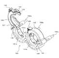
- FIG. 5 is a perspective view of a clamper in a state where a syringe receiver is removed in FIG. 4. It is a front view of the clamper shown in FIG.
- FIG. 7 is a sectional view taken along line AA in FIG. 6. It is a block diagram which shows the electrical structure of a chemical injection device.
- FIG. 2 It is a perspective view explaining the mounting
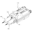
- a fluoroscopic imaging system 1000 having a CT angio apparatus 300 that is a fluoroscopic imaging apparatus and a chemical injection system.
- the chemical solution injection system includes a chemical solution injection device 100 and a syringe assembly 200 (see FIG. 3) attached to the chemical solution injection device 100, which is not shown in FIG.
- the CT angiography apparatus 300 includes an imaging unit 301 that performs an imaging operation and an imaging control unit 302 that controls the operation of the imaging unit 301, which are connected via a communication network.
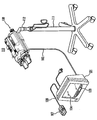
- the chemical injection device 100 includes an injection head 110 that is pivotably attached to an upper portion of a stand 111 via an arm 112, and an injection control that is electrically connected to the injection head 110 via a cable 102.
- the injection control unit 101 includes a main operation panel 103, a touch panel 104 serving as a display unit and an input unit, and a hand unit 107 which is an auxiliary input unit electrically connected to the main body of the injection control unit 101 through a cable 108.
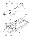
- the injection head 110 is detachably mounted with two sets of syringe assemblies 200 (in FIG. 3, only one set of syringe assemblies 200 is shown for simplicity).
- the syringe assembly 200 includes a syringe 220 and a protective cover 270 into which the syringe 220 is inserted.
- the syringe 220 is a syringe 220 generally referred to as a rodless syringe, and includes a cylinder 221 having a flange 221a formed at the end and a nozzle portion 221b formed at the tip, and a piston 222 inserted into the cylinder 221 so as to be capable of moving forward and backward. And have.
- the piston 222 is integrally formed with an engagement protrusion (not shown) that engages with a piston drive mechanism 130 described later at the end thereof.
- the filled chemical liquid is pushed out from the syringe 220 through the nozzle part 221b.
- an extension tube (not shown) having an injection needle or catheter connected to the tip is connected to the nozzle portion 221b, the injection needle or catheter is punctured or inserted into the blood vessel of the subject, and the liquid medicine filled in the syringe 220 is supplied to the subject.
- the chemical solution filled in the syringe 220 include a contrast agent, physiological saline, and an anticancer agent.
- one syringe 220 can be filled with a contrast agent, and the other can be filled with physiological saline. .
- both syringes can be filled with an anticancer agent.
- a highly viscous chemical solution such as a contrast medium
- a contrast agent used in an angio apparatus that captures a blood vessel image of a subject has a high viscosity.
- the internal pressure of the cylinder 221 becomes very high. This high internal pressure causes the cylinder 221 to expand, which may cause various problems in injecting the chemical liquid.
- the protective cover 270 suppresses expansion due to an increase in the internal pressure of the cylinder 221 at the time of injecting the chemical solution, and is a component configured in a cylindrical shape so that the outer peripheral surface of the cylinder 221 is inserted with almost no gap.
- the protective cover 270 is formed with a thickness having mechanical strength that can sufficiently withstand the internal pressure acting on the cylinder 221 during the injection of the chemical liquid.
- An opening is formed at the tip of the protective cover 270, and the cylinder 221 is held by the protective cover 270 with the nozzle portion 221b protruding from the opening.
- a cover flange 271 having a recess for receiving the flange 221a of the cylinder 221 is formed at the end of the protective cover 270.
- the injection head 110 has two piston drive mechanisms 130 that are driven to move the pistons 222 of the two syringe assemblies 200 attached to each other in a forward / backward manner, corresponding to positions where the syringe assemblies 200 are attached.
- the piston drive mechanism 130 includes a piston holding mechanism that holds an engagement protrusion formed at the end of the piston 222, and a rod member that is connected to a drive source such as a motor that moves the piston holding mechanism forward and backward.
- the piston holding mechanism is located at the tip of the rod member and can be designed, for example, as a hook configured to engage the engaging protrusion of the piston 222 and thereby hold the engaging protrusion.
- the syringe assembly 200 attached to the injection head 110 can inject the liquid medicine filled in the syringe 220 into the subject separately or simultaneously by the piston 222 being advanced by the piston drive mechanism 130.
- the piston drive mechanism 130 a known mechanism generally used in this type of injection device can be employed.
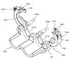
- the tip of the injection head 110 is provided with a syringe receiver 120 and a clamper 140 that constitute a syringe mounting portion on which the syringe assembly 200 is placed.
- the clamper 140 is configured to individually hold the cover flange 271 of each syringe assembly 200.
- the syringe receiver 120 is located on the tip side of the clamper 140 and has two recesses 121 that individually receive the outer peripheral surfaces of the cylinder assemblies 200.
- Each cylinder assembly 200 is positioned in the recess 121 with the nozzle portion 221b facing the tip, and is fixed to the injection head 110 by the cover flange 271 being held by the clamper 140.
- FIGS. 5 and 6 show the syringe receiver 120 removed.
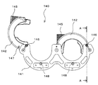
- the clamper 140 includes three shafts 150a, 150b, and 150c, a base member 141, and two flange pressing members 142 that are arranged in parallel at intervals.
- the shafts 150a to 150c also serve as a part of the frame structure of the injection head 110, and support the clamper 140 at the tip.
- the interval between the shafts 150a to 150c is larger than the diameter of the cover flange 271 that is a part of the syringe assembly 200 held by the clamper 140.
- the base member 141 has two flange receiving recesses 141a located between the shafts 150a to 150c.
- the flange receiving recess 141a is formed in an arc shape that is substantially equal to the outer shape of the portion that the flange receiving recess 141a of the cover flange 271 receives so that a part of the cover flange 271 can be received.
- the two flange pressing members 142 receive a remaining portion of the cover flange 271 that is not received by the flange receiving recess 141a and are combined with each flange receiving recess 141a so as to surround the cover flange 271 over the entire circumference. It is an arc-shaped part. Therefore, the inner surface of the flange pressing member 142 has an arcuate groove that is substantially the same as the outer shape of the portion that the flange pressing member 142 of the cover flange 271 receives, like the flange receiving recess 141a.
- Each flange pressing member 142 is rotatably supported at one end by the outer shafts 150a and 150c so as to open and close with respect to the flange receiving recess 141a, and the cover flange 271 can be attached and detached.
- the closed position where 271 is held can be taken.
- the flange pressing member 142 engages with the central shaft 150b to fix the flange pressing member 142 in the closed position at the free end that is opposite to the ends supported by the shafts 150a and 150c.
- An engagement structure is provided.
- the engagement structure may be any structure as long as the flange pressing member 142 can be engaged and released.
- the flange pressing member 142 has a concave portion 143 and a ball plunger 144 arranged on the outer surface of the free end portion.
- the recessed portion 143 is formed in a shape that hangs on the outer peripheral surface of the central shaft 150b when the flange pressing member 142 is in the closed position.
- the ball plunger 144 includes a ball, a casing that accommodates a part of the ball so that the ball can protrude, and a spring that biases the ball in a direction in which the ball protrudes from the casing. It is embedded in the flange pressing member 142 so as to protrude.
- the position of the ball plunger 144 is such that the ball of the ball plunger 144 contacts the shaft 150b and is pushed into the casing while the flange pressing member 142 rotates from the open position to the closed position. It is preferable that the recess 143 is engaged with the shaft 150b immediately after passing. By doing so, the flange pressing member 142 can be favorably held in the closed position. In addition, since the click feeling is obtained when the ball passes through the shaft 150b, the operator can easily recognize that the flange pressing member 142 has reached the closed position.
- the ball plunger 144 as the engagement structure, when the engagement of the flange pressing member 142 in the closed position with the shaft 150b is released, the flange pressing member 142 is simply rotated toward the release position. It's okay. Therefore, in this embodiment, the flange pressing member 142 has a knob 145 at the free end so that the flange pressing member 142 can be easily rotated.
- the base member 141 detects the presence / absence or position of an object in a non-contact manner at a position corresponding to each flange pressing member 142.
- the proximity sensor 146 is provided as a second detector.
- Each flange pressing member 142 is provided with a detection object 147 detected by the corresponding proximity sensor 146 when each flange pressing member 142 is in the closed position.
- the proximity sensor 146 and the detected object 147 are disposed near the rotation center of the flange pressing member 142 and at positions facing each other when the flange pressing member 142 is in the closed position.
- the proximity sensor 146 detects the detected object 147 when the distance to the detected object 147 is equal to or less than a predetermined distance. Therefore, when the flange pressing member 142 is not in the closed position, the distance between the proximity sensor 146 and the detected object 147 is larger than a predetermined distance, but when the flange pressing member 142 is in the closed position, the proximity sensor 146 and the detected object are not detected.
- the proximity sensor 146 and the object to be detected 147 are arranged so that the distance to the 147 is a predetermined distance or less.
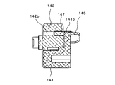
- FIG. 7 is a cross-sectional view taken along the line AA of FIG.
- the base member 141 and the flange pressing member 142 have through-holes 141b and 142b parallel to the rotation shaft of the flange pressing member 142, respectively, and are collinear when the flange pressing member 142 is in the closed position. It is formed in the position to line up.
- the proximity sensor 146 is inserted into the through hole 141b of the base member 141 and fixed.
- the detected object 147 is inserted and fixed in the through hole 142b of the flange pressing member 142.
- the distance between the two decreases as the flange pressing member 142 is rotated from the open position toward the closing position, and the flange pressing member 142 is closed.
- Minimum when in position. Therefore, the position of the proximity sensor 146 in the through hole 141b is larger than the predetermined distance when the flange pressing member 142 is not in the closed position, but is less than the predetermined distance when the flange pressing member 142 is in the closed position.
- proximity sensors detect the presence and position of an object using magnetism as a detection medium.
- the types of magnetism detected by the proximity sensor include a DC static magnetic field and an AC magnetic field, both of which can be used in the present invention.
- a magnet or an electromagnet is used as the object to be detected 147
- a semiconductor magnetic sensor such as a magnetoresistive element or a Hall element, a flux gate type sensor, MR (Magneto-) as the proximity sensor 146.
- MR Magnetic-
- a ferromagnetic magnetic sensor such as a Resistive element or an MI (Magneto-Impedance) element can be used.
- the proximity sensor 146 that detects a DC static magnetic field uses a magnet or an electromagnet as the detected object 147.
- the magnet When attaching the magnet to the flange pressing member 142, there is a concern that the magnet may be attached with the polarity reversed.
- the electromagnet requires an operation circuit for the electromagnet separately from the detection circuit for the proximity sensor 147.
- a proximity sensor 146 using an AC magnetic field as a detection medium which can use a metal as the object to be detected 147 and thereby does not cause the above-described problem.
- the proximity sensor 146 using an AC magnetic field as a detection medium has a shorter distance at which the detection object 147 can be detected than a proximity sensor using a DC static magnetic field as a detection medium such as a Hall element, so the flange pressing member 142 is closed. The position can be detected more accurately.
- the proximity sensor 146 using an AC magnetic field as a detection medium has a coil.
- a constant AC current is supplied from an AC power source to the coil and an AC magnetic field is applied to a metal (detected object 147)
- an eddy current is generated in the metal.
- the eddy current generated in the metal generates a magnetic field, and an induced voltage is generated in the coil.
- the impedance of the coil which is the ratio of the voltage generated in the coil to the current passed through the coil, changes, and the proximity sensor 146 uses this change in impedance to detect the metal. .
- one coil has a function as an excitation coil that applies an alternating magnetic field to the detected object 147 and a function as a detection coil that detects an eddy current magnetic field generated from the detected object 147. It can be roughly divided into a single coil type and a multi-coil type having a plurality of coils.
- the types of the single-coil proximity sensor 146 include a high-frequency oscillation type and a filter type.
- the high-frequency oscillation type proximity sensor 146 incorporates a detection coil in a part of the oscillation circuit, and detects a change in oscillation amplitude or oscillation frequency in accordance with the impedance change.
- the filter-type proximity sensor 146 uses the fact that the detection coil is incorporated in a part of the LC or LR filter circuit, and the filter characteristics change due to the impedance change of the detection coil.
- the types of the multi-coil proximity sensor 146 include a double coil type, a differential coil type, and a hawk coil type.
- the double-coil proximity sensor 146 uses two coils having the same structure, one of which is used as a detection coil and close to the detected object 147, and the other is used as a reference coil so as not to be affected by the detected object 147. . If the two coils are excited under the same conditions and the difference in induced voltage is compared, the detection coil is affected by the approach of the detected object 147. Therefore, the difference between the two induced voltages is due to the approach of the detected object 147. It means that.
- a method of the detection circuit a method is generally used in which an impedance bridge is constituted by two coils, and this is excited by a fixed oscillator to detect the amplitude of the unbalanced voltage and the phase with respect to the excitation current. Alternatively, there is a method in which the unbalanced voltage obtained from the bridge circuit is amplified and fed back to the excitation side of the bridge circuit to oscillate the circuit and detect its amplitude.
- the detection coils are arranged at symmetrical positions on both sides of the exciting coil, and the terminals of the detection coil are connected in series reverse polarity to serve as detection output terminals. Since the exciting magnetic flux generates an induced voltage equal to the detection coil, the induced voltage due to the exciting magnetic flux is canceled, and only the induced voltage due to the magnetic flux generated by the eddy current can be taken out as in the double coil type. After that, similarly to the double coil type, the amplitude and phase of the output voltage of the detection coil terminal may be detected, or the voltage of the detection coil terminal may be amplified and fed back to the excitation coil to oscillate.
- the hawk coil type proximity sensor 146 has an excitation coil and a detection coil arranged to face each other to create a magnetic coupling, and an amplitude or phase change of an induced voltage generated in the detection coil by inserting a detected object 147 therebetween. Is detected.
- the proximity sensor 146 that can detect metal in a non-contact manner using an AC magnetic field as a detection medium has been described above. Any of these can be used in the present invention, and among them, a high-frequency oscillation type single-coil proximity sensor such as E2E-X1C1 manufactured by OMRON Corporation can be preferably used.
- the entire object 147 may be made of metal, or a part thereof may be made of metal.
- the size and shape of the object to be detected 147 can be arbitrarily set as long as the opening / closing operation of the flange pressing member 142 is not hindered.
- the detected object 147 may be a ball plunger.
- a ball plunger similar to the ball plunger 144 (see FIG. 5) provided in the flange pressing member 142 in order to fix the flange pressing member 142 in the closed position can be used.
- the ball plunger When a ball plunger is used as the object to be detected 147, the ball plunger is fixed to the flange pressing member 142 by projecting a part of the ball from the surface of the flange pressing member 142 facing the base member 141. A part of the protruded ball engages with the through hole 141b that holds the proximity sensor 146 when the flange pressing member 142 is in the closed position. Thereby, the detected object 147 can have an auxiliary function of the ball plunger 144 that locks the flange pressing member 142 in the closed position.
- the proximity sensor 146 and the object 147 to be detected are fixed in the through holes 141b and 142b so as not to be displaced. Therefore, the proximity sensor 146 and the detected object 147 can be press-fitted into the through holes 141b and 142b. Alternatively, the proximity sensor 146 may be screwed. Thereby, the position adjustment of the proximity sensor 146 in the through hole 141b and the removal for replacement of the proximity sensor 146 can be easily performed.
- the through hole 141b is preferably filled with resin. Thereby, the waterproof property of the proximity sensor 146 is enhanced, and the possibility that the proximity sensor 146 may fail when a chemical solution or the like adheres to the clamper 140 can be reduced.
- the ball plunger 144 is used for the engagement structure for locking the flange pressing member 142 in the closed position.
- the proximity sensor 147 is connected to the flange pressing member 142 in the closed position.
- it can also be placed on the portion of the base member 141 that faces the ball plunger 144. By doing so, the ball plunger 144 constituting the engagement structure can be used as an object to be detected, and the construction of the clamper 140 can be simplified.
- each syringe assembly 200 is provided with a detection object 272 that can be detected by the proximity sensor 148 in a non-contact manner.
- the cover flange 271 of the protective cover 270 has a convex portion 271 a protruding further in the radial direction from the cover flange 271 in a part in the circumferential direction, and the object 272 to be detected is It is installed on the convex portion 271a.
- each flange receiving recess 141a of the clamper 140 is formed with a groove 141c.
- the groove portion 141c receives the convex portion 271a of the protective cover 270 when the syringe assembly 200 is attached to the clamper 140, thereby preventing the syringe assembly 200 from rotating in the circumferential direction.
- the proximity sensor 148 is disposed at a position where the detected object 272 is detected when the convex portion 271a of the protective cover 270 is normally received in the groove portion 141c of the clamper 140.
- the usable proximity sensor 148 and the detected object 272 are the same as the proximity sensor 146 and the detected object 147 for detecting that the flange pressing member 142 is in the closed position.
- the proximity sensor 148 that detects that the convex portion 271a of the protective cover 270 is normally received in the groove portion 141c of the clamper 140 is configured to detect the types of the protective cover 270 corresponding to various sizes of the syringe 220. May be.
- a proximity sensor such as a semiconductor magnetic sensor using a DC static magnetic field as a detection medium can detect a plurality of patterns from a combination of N and S poles. Like the proximity sensor, it can be preferably used.
- the attachment of the proximity sensor 148 to the clamper 140 and the attachment of the detected object 272 to the protective cover 270 are also performed on each member in the same manner as the proximity sensor 146 and the detected object 147 for detecting opening and closing of the flange pressing member 142. This can be done by forming holes and fixing the proximity sensor 148 and the object 272 to be detected in the holes, respectively. These fixing methods may be the same as the fixing method of the proximity sensor 146 and the detected object 147.
- FIG. 8 shows a block diagram of the main electrical configuration of the chemical injection device of this embodiment.
- Each block shown in FIG. 8 exists as at least a part of the configuration described in FIGS. 1 to 7 or a combination of at least a part thereof, and may be configured as hardware or configured as a logic circuit. May be.
- the injection control unit 101 includes a control unit 161, an input unit 162, a display unit 163, and an interface (I / F) 164.
- the input unit 162 corresponds to the main operation panel 103 and the touch panel 104 shown in FIG. 2, and accepts input of data necessary for determining various settings of the chemical solution injection device 100 and chemical injection conditions by the operator.
- the display unit 163 corresponds to the touch panel 104 shown in FIG. 2, and displays a screen representing the operating state of the chemical solution injector 100 and a data input screen. As described above, in this embodiment, the touch panel 104 has both a function as a part of the input unit 162 and a function of the display unit 163.
- the control unit 161 calculates a chemical injection condition based on an input from the input unit 162, displays necessary information on the display unit 163, or drives the piston driving mechanism 130 according to the calculated injection condition.
- the overall operation of the chemical liquid injector 100 is controlled.
- the control unit 161 is connected to the proximity sensors 146 and 148 and the piston drive mechanism 130 of the injection head 110, and necessary information is based on signals from the proximity sensors 146 and 148 and other sensors (not shown). Is displayed on the display unit 163, or the operation of the piston drive mechanism 130 is controlled.
- the control unit 161 can be configured by a computer unit including a CPU, a RAM, and a ROM.
- a control signal for the operation of the piston drive mechanism 130 emitted from the control unit 161 and a part of the injection condition of the chemical solution calculated by the control unit 161 are sent to the angio device 300 via the interface 164, thereby The chemical injection device 100 and the angio device 300 can be interlocked.
- the operator turns on the power of the chemical liquid injector 100 and then attaches the syringe assembly 200 filled with the chemical liquid to be injected to the subject to the injection head 110.
- a chemical solution container (not shown) is connected to the nozzle portion 221b via a tube or a suction tube, and the piston 222 is retracted in that state.
- the syringe assembly 200 may be filled with a chemical solution, and the syringe assembly 200 filled with the chemical solution may be attached to the injection head.
- the former type is referred to as a prefilled type
- the latter type is also referred to as a post-filling type.
- the cover flange 271 is positioned on the flange receiving recess 141a (see FIG. 5) with the flange pressing member 142 in the open position.
- the syringe assembly 200 is mounted on the syringe receiver 120 so that the convex part 271a (refer FIG. 3) is inserted in the groove
- the position of the piston 222 in the cylinder 221 is set to a predetermined position.
- the chemical injection device 100 performs an initialization operation of the piston holding mechanism 130 when the power is turned on.
- the piston holding mechanism is in a state where the syringe assembly 200 is placed on the syringe receiver 120.
- the piston drive mechanism is operated so as to be in the initial position for engaging with the engaging protrusion of the piston 222.
- the initial position of the piston holding mechanism is the end of the moving range of the piston holding mechanism, and the position of the piston holding mechanism can be detected by a sensor (not shown).
- any sensor can be used as this sensor, but an optical sensor such as a transmissive photosensor (photointerrupter) or a reflective photosensor can be preferably used.
- the transmissive photosensor may be used as a linear encoder or a rotary encoder in combination with a slit plate supported so as to move linearly or rotate in conjunction with a piston holding mechanism.
- the plate plate In combination with a plate member supported so as to move linearly in conjunction with the piston holding mechanism, the plate plate is positioned between the light emitting element and the light receiving element of the transmissive photosensor when the piston holding mechanism is in the initial position.
- it may be used as a limit sensor configured to block light from the light emitting element.
- a reflective photosensor basically the same as the above as an encoder except that the slit plate and the plate member block the light from the light emitting element or reflect it toward the light receiving element. It can be used as a limit sensor. Furthermore, it can also be set as the structure provided with both the encoder and the limit sensor using the some optical sensor.
- the piston holding mechanism is waiting at the initial position by the initialization operation of the piston driving mechanism 130. Therefore, when the syringe assembly 200 is placed on the syringe receiver 120, at the same time, the piston holding mechanism is engaged with the engagement protrusion of the piston 222.
- the engagement between the piston holding mechanism and the engagement protrusion of the piston 222 can be detected by a sensor (not shown).
- the amount of chemical liquid injected into the subject and the amount of chemical liquid sucked into the syringe 220 are generally based on the assumption that the movement amount of the piston 222 is equal to the movement amount of the piston holding mechanism. Is calculated based on If the engagement protrusion of the piston 222 and the piston holding mechanism are separated in the initial state, the piston 222 does not move until the piston holding mechanism comes into contact with the engagement protrusion, and the amount of movement of both does not move. The amount cannot be calculated.
- the piston 222 may be pushed more than necessary, and the syringe 220 may be damaged. Accordingly, the engagement between the piston holding mechanism and the engagement protrusion of the piston 222 can be detected, and the detection result is indicated to the operator by display or voice, or the next operation is performed until it is detected that the engagement is detected. It is possible to prevent the above-mentioned problems by preventing the process from proceeding to the above.
- the engagement between the piston holding mechanism and the engagement protrusion of the piston 222 can be detected by, for example, a strain sensor, an infrared sensor, a color recognition CCD sensor, a color identification sensor, and a mechanical switch.
- the operator rotates the flange pressing member 142 to engage the engagement structure with the central shaft 150b, as shown in FIG.
- the member 142 is locked in the closed position.
- the cover flange 271 is fixed to the syringe holder 140 and the syringe assembly 200 is attached to the injection head 110.
- An injection needle or catheter is connected to the syringe assembly 200 via an extension tube, and the injection needle or catheter is punctured or inserted into the blood vessel of the subject, so that the drug solution filled in the syringe assembly 200 is supplied to the subject. You will be ready to inject.
- the injection needle or catheter may be punctured or inserted before or after the syringe assembly 200 is mounted on the injection head 110, but in the case of the empty syringe assembly 200, the syringe assembly is inserted. After 200 is filled with the chemical solution.
- a branch tube (not shown) equipped with an appropriate valve device, etc. Can also puncture or insert an injection needle or catheter prior to filling the syringe assembly 200 with a drug solution.
- the proximity sensor 148 detects the object 272 to be detected of the syringe assembly 200, and accordingly, the syringe assembly 200 is mounted on the injection head 110. Detected. Further, when the flange pressing member 142 is locked at the closed position, the proximity sensor 146 detects the detected object 147 of the flange pressing member 142, thereby detecting that the flange pressing member 142 is locked at the closed position.
- the proximity sensor 146 actually detects that the flange pressing member 142 is in the closed position and does not detect that the flange pressing member 142 is locked in the closed position. However, since the flange pressing member 142 reaches the closed position, it is locked in that position by the engaging structure, so that the proximity sensor 146 substantially detects that the flange pressing member 142 is locked in the closed position. It's okay.
- the flange pressing member 142 holds the syringe assembly 200 by receiving the cover flange 271 over the entire circumference in cooperation with the flange receiving recess 141a. Therefore, in a state where the flange pressing member 142 is locked at the closed position, the syringe assembly 200 is fixed to the clamper 140 and attached to the injection head 110 at the correct position and posture.
- the proximity sensor that detects that the syringe assembly 200 is mounted on the clamper 140 by configuring the clamper 140 to hold the syringe assembly 200 by surrounding the entire circumference of the cover flange 271.
- Two sensors 148 and a proximity sensor 146 that detects that the clamper 140 is locked in the closed position can detect that the syringe assembly 200 is mounted on the injection head 110 in the correct posture.
- the control unit 161 When the syringe assembly 200 is mounted on the injection head 110 as described above, detection signals are sent from the proximity sensors 146 and 148 to the control unit 161.
- the controller 161 receives the detection signals from the proximity sensors 146 and 148, whether the attached syringe assembly 200 is a prefilled type or a post-filling type, from another viewpoint, the control unit 161 is a syringe assembly 200 filled with a chemical solution.
- the following processing is executed. If the sensor is configured to detect the initial position of the piston holding mechanism, in addition to the detection signals from the proximity sensors 146 and 148, a sensor that detects that the piston holding mechanism is at the initial position. Is output to the control unit 161, and the control unit 161 receives these three detection signals, whereby the control unit 161 executes the following processing.
- the type of the attached syringe assembly 200 can be determined by the operator inputting, for example, the type of the attached syringe assembly 200 through the input unit 162 and the control unit 161 determining from the input result.
- the syringe assembly 200 includes an RFID chip (not shown) and the chemical injection device 100 includes an RFID reader (not shown), and the control unit 161 is based on the reading result of the RFID chip by the RFID reader.
- the information recorded on the RFID chip includes at least information on whether the syringe is a prefilled type or a post-filling type.
- the syringe assembly 200 is filled with the chemical solution by connecting the tip of the syringe assembly 200 to a chemical solution container (not shown), and in this state, the piston 222 is retracted by the piston drive mechanism 130, and the chemical solution in the chemical solution container is transferred to the syringe assembly 200. This can be done by sucking in. Prior to this suction operation, the controller 161 causes the piston drive mechanism 130 to perform the suction preparation operation described below.
- control unit 161 operates the piston drive mechanism 130 so that the piston 222 is pushed toward the tip of the syringe assembly 200 and is positioned at the forward end position that is the most advanced position inside the cylinder 221. All the air in the syringe 220 is pushed out.
- the injection needle or catheter is not punctured or inserted into the subject, or the path from the syringe 220 to the injection needle or catheter is blocked, and the syringe 220 and the subject's blood vessel are in fluid communication. Absent.
- the forward end position can be the forward end position of the piston holding mechanism, and the forward end position of the piston holding mechanism can be detected by a sensor similar to the sensor that detects the initial position of the piston holding mechanism.
- a sensor similar to the sensor that detects the initial position of the piston holding mechanism Good. That is, when the sensor for detecting the initial position of the piston holding mechanism is a rotary encoder or a linear encoder, this encoder can also be used as a sensor for detecting the forward end position of the piston holding mechanism.
- the sensor that detects the initial position of the piston holding mechanism is a limit sensor and has a plate member that moves linearly in conjunction with the piston holding mechanism, a transmission type or reflective type photo sensor is provided separately from this limit sensor.
- the plate member When the piston holding mechanism is at the forward end position, the plate member operates with a transmissive or reflective photosensor (if the photosensor is transmissive, the plate member blocks light from the light emitting element and When the sensor is a reflection type, the plate member is arranged so that the light from the light emitting element is reflected toward the light receiving element.
- a limit sensor may be further added so that the forward end position of the piston holding mechanism can also be detected by this limit sensor.
- the control unit 161 operates the piston drive mechanism 130 so that the piston 222 is automatically positioned at the foremost inside of the cylinder 221, for example, Even if the operator misunderstands the syringe 220 that has not been filled with the chemical solution as if it had been filled with the chemical solution and causes the chemical injection device to execute the chemical injection operation, the piston 222 moves forward further. Can not do it. Therefore, it is possible to reliably prevent a medical accident that air is injected into the blood vessel of the subject.
- the control unit 161 can also display information indicating that the syringe assembly 200 is correctly mounted, that is, that the mounting of the syringe assembly 200 is completed, on the display unit 163 together with the above-described suction preparation operation. Thereby, the operator can confirm easily that mounting
- display of information indicating that the attachment of the syringe assembly 200 is completed can be executed alone.
- the information displayed on the display unit 163 may be a message by text or information represented by a symbol.
- the display unit 163 includes a light emitting lamp (not shown), and lighting the light emitting lamp may indicate that the mounting of the syringe assembly 200 is completed.
- the light emitting lamp may be arranged in the injection head 110.
- a speaker (not shown) may be further added to the chemical injection device 100, and from this speaker, the fact that the syringe assembly 200 is correctly attached may be notified by voice, or the display and voice may be combined.
- control unit 161 When the control unit 161 receives a detection signal only from the proximity sensor 148 that detects the detection object 272 of the syringe assembly 200, the control unit 161 determines that the syringe assembly 200 is not mounted, and displays that fact. 163 is displayed to alert the operator. Alternatively, when the control unit 161 receives a detection signal only from the proximity sensor 146 that detects the detected object 147 of the flange pressing member 142, the control unit 161 determines that the syringe assembly 200 is not normally held, This is displayed on the display unit 163 to alert the operator.
- the operator confirms that the syringe assembly 200 has been correctly attached, and when the fact is input via the input unit 162, the control unit 161 starts an operation for injecting the chemical solution. More specifically, the control unit 161 causes the display unit 163 to display an operation mode selection screen and / or an injection condition setting screen of the chemical solution injection device 100 and allows the input unit 162 to select an operation mode and / or Or, an input operation for setting injection conditions is made possible.
- the operation for injecting the chemical liquid includes not only an operation directly related to the chemical liquid injection but also an operation of sucking the chemical liquid into the syringe 220 as a pre-stage of the chemical liquid injection, and the operation is performed when the syringe assembly 200 is a post-fill type.
- the mode includes a suction mode. Therefore, when the attached syringe assembly 200 is a post-filling type (empty syringe), the operator confirms that the syringe 220 and the blood vessel of the subject are not in fluid communication with each other, and then performs a suction operation on the liquid injector 100. After that, the injection operation to the subject is executed.
- a post-filling type empty syringe
- the control unit 161 When the operation mode selection screen and / or the injection condition setting screen are displayed on the display unit 163, the operator selects an operation mode or inputs data as necessary. Based on this input, the control unit 161 performs necessary processing and controls the piston drive mechanism 130 to inject a drug solution from the syringe assembly 200 to the subject. Since these operations may be the same as those of a normal chemical solution injector, detailed description thereof is omitted.
- the chemical solution is kept without being attached or not being correctly attached by preventing the control unit 161 from proceeding to the next step.
- the injection operation can be prevented from being executed. If the chemical solution injection operation is performed without the syringe assembly 200 being correctly attached, an accident such as the syringe assembly 200 being detached during the chemical solution injection may occur. Therefore, by making it possible to detect that the syringe assembly 200 is correctly attached as in this embodiment, such an accident can be prevented.
- the cover flange 271 can receive a force on the entire circumference when the chemical solution is injected.
- the force received by the cover flange 271 during the injection of the chemical liquid is distributed over the entire circumference of the cover flange 271, and even when the chemical liquid is injected at a high pressure, the possibility that the cover flange 271 is damaged is extremely low.
- the output from the sensor can be changed according to the type of metal to be detected. If a different kind of metal is used for each detection object 272, it is possible to determine not only that the syringe assembly 200 is mounted but also the type of the syringe assembly 200 that is mounted.
- the types of the syringe assembly 200 are classified by, for example, the concentration of the active ingredient of the filled chemical solution (typically, the iodine concentration in the contrast medium), the volume and size of the syringe 220, and combinations thereof. Can do.
- the proximity sensor 148 is used as the first detector that detects that the syringe assembly 200 is placed on the placement unit.
- a syringe is used. No proximity sensor is required to detect the assembly.
- Some recent chemical injection systems include an RFID chip in a syringe and an RFID reader that acquires data from the RFID chip in a chemical injection device.
- Various data such as data relating to a filled chemical solution and data relating to a subject are recorded on the RFID chip as necessary.
- the chemical injection device can use the data acquired from the RFID chip to calculate the chemical injection conditions, record the use history of the syringe, and record the chemical injection history of the subject.
- an RFID reader is installed at a position where data can be acquired from the RFID chip with the syringe attached. Therefore, if the RFID reader can acquire data from the RFID chip, this means that the syringe is attached to the chemical solution injector. That is, the RFID reader can also serve as the first detector, and in this case, the proximity sensor 148 is unnecessary.
- the RFID reader has a wider detectable range than the proximity sensor, and may detect the syringe assembly 200 even if there is a positional deviation when the cover flange 271 is placed on the flange receiving recess 141a of the clamper 140.
- the detection of the cylinder assembly 200 does not require such high positional accuracy. Misalignment is not a problem.
- the first detector is not limited to the proximity sensor 148 and the RFID reader described above, and any detector can be used, and the position of the first detector is also arbitrary.
- the RFID chip may be mounted on the cylinder 221, may be mounted on the protective cover 270, or may be mounted on both. Good.
- the RFID reader is installed at a position where the RFID chip can be read when the syringe assembly is mounted on the injection head according to the position of the RFID chip.
- the protective cover 270 is not essential in the present invention.
- a syringe assembly that is filled with a chemical solution having a viscosity that is not so high is often not equipped with a protective cover.
- the clamper is configured to hold a flange formed at the end of the cylinder.
- the RFID chip is mounted on the cylinder.
- a weight sensor is further provided in a syringe mounting part, and it is mounted in the syringe mounting part by this weight sensor. It may be possible to detect whether the syringe assembly is filled with a chemical solution. In this case, it is preferable that a warning is displayed and / or sounded to the operator if the syringe assembly is not filled with a chemical solution.
Abstract
シリンジが正しい姿勢でセットされたことをより簡単な構成で検出できる薬液注入装置を提供する。 シリンジアセンブリ200が着脱自在に装着される注入ヘッド110は、シリンジアセンブリ200のカバーフランジ271を全周にわたって包囲することによってシリンジアセンブリ200を固定するクランパ140を有する。クランパ140は、クランパ140は、ベース部材と、ベース部材に回動自在に支持されたフランジ押え部材と、フランジ押え部材を閉止位置でロックする係合構造とを有する。ベース部材には、クランパ140に載せられたシリンジアセンブリ200を検出する近接センサと、フランジ押え部材が閉止位置でロックされたことを検出する近接センサとを有する。
Description
本発明は、シリンジ内に充填された薬液を被験者に注入するための薬液注入装置および薬液注入システムに関する。
医療用の画像診断装置としては、CT(Computed Tomography)スキャナ、MRI(Magnetic Resonance Imaging)装置、PET(Positron Emission Tomography)装置、アンギオ装置、およびMRA(MR Angio)装置などがある。これらの装置を使用して被験者の透視画像を撮像する際は、被験者に造影剤や生理食塩水などの薬液を注入することが多い。
被験者への薬液の注入は、薬液注入装置を用いて自動的に行うのが一般的である。薬液注入装置は、薬液を充填したシリンジが着脱自在に装着される注入ヘッドと、注入ヘッドの動作を制御する注入制御ユニットとを有している。シリンジは、シリンダと、シリンダ内に前進および後退移動可能に挿入されたピストンとを有しており、薬液はシリンダ内に充填されている。
注入ヘッドは、シリンダの末端部に形成されたフランジを保持することによってシリンダを注入ヘッドに固定するためのクランパと、シリンダが注入ヘッドに固定された状態でピストンを移動させるピストン駆動機構とを備えている。シリンダの先端部に延長チューブを介して注入針を接続し、注入針を被験者の血管に穿刺した後、ピストン駆動機構によってピストンをシリンダ内に押し込むことで、シリンジに充填されている薬液を被験者に注入することができる。
シリンジに充填された薬液を注入する薬液注入装置では、薬液を注入するとき、ピストンは比較的高い押圧力でシリンダ内に押し込まれる。よって、正確な注入量で、かつ安全に薬液を注入するためには、薬液の注入中に、ピストンの押圧力によってシリンダの位置がずれたりシリンダがクランパから外れたりしないように、シリンジが正規の位置で確実に固定されており、その状態でピストン駆動機構が動作されることが重要である。
そこで、特許文献1には、シリンダが、XYZ方向(互いに直交する3方向)において正しい姿勢でセットされ、かつ、ピストンがピストン駆動機構に正しくセットされたことを検出する検出手段と、シリンジが正しくセットされていないときに警告表示を行なう表示部とを備えた注入装置が開示されている。
特許文献1:特開2007-306990号公報
しかしながら、特許文献1に開示された注入装置では、シリンジを固定するためのクランパはシリンダの外周面を上方から押さえ付けることによって保持する構造であるため、シリンジが正しい姿勢でセットされていなくても保持することは可能である。そのため、シリンジが正しく装着されていることを検出するためには、検出手段として、シリンジが正しい姿勢でセットされたことを検出するための、XYZの各方向用に設けられたセンサ、およびピストンがピストン駆動機構に正しくセットされたことを検出するセンサの合計4つのセンサを用いている。このようにシリンジの検出に関することだけでも4つのセンサを備える結果、注入装置の構造が複雑になる。しかもこの数は1本のシリンジに対する数であって、例えば2本のシリンジを搭載する注入装置の場合は8個のセンサが必要である。
また、特許文献1に開示された注入装置では、クランパが上記のような構造であるので、保持力が十分ではなく、シリンジが正しい姿勢でセットされていたとしても、ピストン駆動機構の動作によりシリンジが正規の位置からずれてしまう場合があった。
そこで本発明は、シリンジが正しい姿勢でセットされたことをより簡単な構成で検出できる薬液注入装置および薬液注入システムを提供することを目的とする。
本発明の薬液注入装置は、シリンダおよびピストンを有するシリンジアセンブリが着脱自在に装着され、装着されたシリンジアセンブリを操作することによってシリンジアセンブリから被験者へ薬液を注入する薬液注入装置であって、シリンジアセンブリが載せられるシリンジ載置部と、シリンジアセンブリを固定するクランパと、第1の検出器と、第2の検出器とを有する。
クランパは、シリンジ載置部の一部を構成し、フランジが載せられるベース部材と、開放位置と閉止位置との間で回動自在にベース部材に支持されたフランジ押え部材と、フランジ押え部材を閉止位置でロックする係合構造とを有し、ベース部材および閉止位置でロックされたフランジ押え部材でフランジを全周にわたって包囲することによってシリンジアセンブリを固定する。第1の検出器は、シリンジアセンブリがシリンジ載置部に載置されたことを検出する。第2の検出器は、フランジ押え部材が閉止位置でロックされたことを検出する。
本発明の薬液注入装置において、ベース部材およびフランジ押え部材は、フランジを受け入れる凹部を有することができる。
また、第2の検出器は、ベース部材に設置された近接センサであり、フランジ押え部材には、フランジ押え部材が閉止位置にあるときに近接センサによって検出される被検出物が配置されていることが好ましい。この場合、近接センサおよび被検出物は、フランジ押え部材が閉止位置にあるときに近接センサと被検出物との距離が最小となるように配置されていていてもよい。また、近接センサは、交流磁界を検出媒体として金属を非接触で検出するセンサであり、被検出物は、近接センサで検出される金属を含んでいる構成とすることで、フランジ押え部材が閉止位置にロックされたことを、より高い精度で検出することができる。
本発明の薬液注入装置は、薬液注入装置の動作全般を制御する制御部と、情報を表示する表示部と、をさらに有していてもよく、この場合、制御部は、第1の検出器によって、シリンジアセンブリがシリンジ載置部に載置されたことが検出され、かつ、第2の検出器によって、フランジ押え部材が閉止位置でロックされたことが検出されると、シリンジアセンブリの装着が完了したことを表す情報を表示部に表示させるようにすることで、操作者は、フランジ押え部材がロックされたことを容易に確認できる。また、制御部は、情報の表示に基づく操作者の所定の操作によって、薬液の注入のための動作を開始するように構成することで、シリンジアセンブリが正しく装着されていないことによる誤動作が防止される。
本発明の薬液注入装置は、ピストンを前進および後退させるピストン駆動機構をさらに有しており、シリンジシリンジ載置部に載せられたシリンジアセンブリが、薬液が充填されていない空シリンジである場合、制御部は、第1の検出器によって、シリンジアセンブリがシリンジ載置部に載置されたことが検出され、かつ、第2の検出器によって、フランジ押え部材が閉止位置でロックされたことが検出されると、ピストンがシリンダの内部最先端に位置するようにピストン駆動機構を動作させることが好ましい。
本発明は薬液注入システムも提供する。本発明の薬液注入システムは、上記本発明の薬液注入装置と、この薬液注入装置に着脱自在に装着される、薬液が充填されたシリンジアセンブリと、を有する。
本発明の薬液注入システムにおいて、薬液注入装置の第1の検出器は近接センサであり、シリンジアセンブリが薬液注入装置のシリンジ載置部に載せられているときに、第1の検出器である近接センサによって検出される被検出物がシリンジアセンブリに配置されていてもよい。あるいは、シリンジアセンブリは、データが記録されたRFIDチップをさらに有し、薬液注入装置は、シリンジアセンブリがシリンジ載置部上に載せられた状態でRFIDチップからデータを取得するRFIDリーダをさらに有し、RFIDリーダが、第1の検出器としても働くように構成することもできる。
また、シリンジアセンブリは、薬液が充填された、シリンダおよびピストンを備えたシリンジと、薬液注入時のシリンダの内圧上昇による膨張を抑制するためにシリンジが挿入される保護カバーと、を有し、フランジが保護カバーに形成されていてもよい。
本発明によれば、クランパはシリンジアセンブリのフランジを全周にわたって包囲し、これによって、シリンジアセンブリが正しい姿勢および位置で固定される。その結果、第1および第2の検出器のみで、シリンジアセンブリが正しい姿勢で薬液注入装置に装着されたことを検出することができる。特に、第2の検出器として、非接触で金属を検出できる近接センサを用い、その近接センサが検出する被検出物を、フランジ保持部材が閉止位置にあるときに近接センサで検出できる位置に配置することで、フランジ保持部材が閉止位置でロックされたことをより高い精度で検出することができる。
図1を参照すると、透視撮像装置であるCTアンギオ装置300と薬液注入システムとを有する、本発明の一実施形態による透視撮像システム1000が示される。薬液注入システムは、薬液注入装置100と、図1では示していないが、薬液注入装置100に装着されるシリンジアセンブリ200(図3参照)とを有している。CTアンギオ装置300は、撮像動作を実行する撮像ユニット301と、撮像ユニット301の動作を制御する撮像制御ユニット302とを有しており、これらは通信ネットワークを介して接続されている。
薬液注入装置100は、例えば図2に示すように、スタンド111の上部にアーム112を介して旋回可能に取り付けられた注入ヘッド110と、ケーブル102で注入ヘッド110と電気的に接続された注入制御ユニット101とを有している。注入制御ユニット101は、メイン操作パネル103、表示手段と入力手段を兼ねたタッチパネル104、およびケーブル108で注入制御ユニット101の本体に電気的に接続された、補助的な入力手段であるハンドユニット107等を備えている。
注入ヘッド110は、図3に示すように、2組のシリンジアセンブリ200を並列に着脱自在に装着する(図3では、簡略化のために1組のシリンジアセンブリ200のみを示している)。
シリンジアセンブリ200は、シリンジ220と、シリンジ220が挿入される保護カバー270とを有する。シリンジ220は、一般にロッドレスシリンジと呼ばれるシリンジ220であり、末端にフランジ221aが形成されるとともに先端にノズル部221bが形成されたシリンダ221と、シリンダ221内に進退移動可能に挿入されたピストン222とを有している。ピストン222は、その末端に、後述するピストン駆動機構130が係合する係合突起(不図示)が一体に形成されている。
ピストン222がシリンダ221の先端へ向けて移動することで、充填されている薬液が、ノズル部221bを介してシリンジ220から押し出される。先端に注入針またはカテーテルが接続された延長チューブ(不図示)をノズル部221bに連結すれば、注入針またはカテーテルを被験者の血管に穿刺または挿入して、シリンジ220に充填されている薬液を被験者に注入することができる。シリンジ220に充填される薬液としては、造影剤、生理食塩水および抗ガン剤などが挙げられ、例えば、一方のシリンジ220に造影剤を充填し、もう一方に生理食塩水を充填することができる。あるいは、両方のシリンジに抗ガン剤を充填することもできる。
このように、薬液注入システムにおいては、造影剤のように粘度の高い薬液を用いることが多い。造影剤の中でも特に、被験者の血管画像を撮像するアンギオ装置に用いる造影剤は粘度が高い。粘度の高い薬液を被験者に注入するとき、シリンダ221の内圧が非常に高くなる。この高い内圧は、シリンダ221を膨張させ、これによって薬液の注入に種々の不具合が生じることがある。
保護カバー270は、薬液注入時のシリンダ221の内圧上昇による膨張を抑制するものであり、シリンダ221の外周面がほぼ隙間なく挿入されるように円筒状に構成された部品である。この保護カバー270の役割を果たすため、保護カバー270は、薬液注入中にシリンダ221に作用する内圧に十分に耐え得る機械的強度を有する肉厚で形成されている。
保護カバー270の先端には開口部が形成されており、シリンダ221は、この開口部からノズル部221bを突出させた状態で保護カバー270に保持される。保護カバー270の末端には、シリンダ221のフランジ221aを受け入れる凹部が形成されたカバーフランジ271が形成されている。
注入ヘッド110には、装着された2組のシリンジアセンブリ200のピストン222を前進/後退操作するために互いに駆動される2つのピストン駆動機構130が、各シリンジアセンブリ200が装着される位置に対応して設けられている。ピストン駆動機構130は、ピストン222の末端に形成された係合突起を保持するピストン保持機構と、ピストン保持機構を前進および後退移動させる、モータ等の駆動源と連結されたロッド部材とを有する。ピストン保持機構は、ロッド部材の先端に位置しており、例えば、ピストン222の係合突起に係合し、それによって係合突起を保持するように構成されたフックとして設計することができる。
注入ヘッド110に装着されたシリンジアセンブリ200は、ピストン駆動機構130によってピストン222が前進させられることによって、シリンジ220内に充填されている薬液を、別々に、または同時に被験者に注入することができる。ピストン駆動機構130については、この種の注入装置に一般に用いられている公知の機構を採用することができる。
注入ヘッド110の先端部には、シリンジアセンブリ200が載せられるシリンジ載置部を構成するシリンジ受け120およびクランパ140が備えられている。クランパ140は、各シリンジアセンブリ200のカバーフランジ271を個別に保持するように構成されている。シリンジ受け120は、クランパ140よりも先端側に位置しており、各シリンダアセンブリ200の外周面を個々に受け入れる2つの凹部121を有している。各シリンダアセンブリ200は、ノズル部221bを先端側に向けた状態で凹部121内に位置され、カバーフランジ271がクランパ140によって保持されることで注入ヘッド110に固定される。
以下に、クランパ140について、図4~6等を参照して説明する。構成をわかりやすくするため、図5および図6は、シリンジ受け120を取り外した状態で示している。
クランパ140は、互いに間隔をあけて並列に配置された3本のシャフト150a、150b、150cと、ベース部材141と、2つのフランジ押え部材142とを有する。
シャフト150a~150cは、注入ヘッド110のフレーム構造の一部を兼用しており、その先端部でクランパ140を支持している。各シャフト150a~150cの間隔は、クランパ140が保持するシリンジアセンブリ200の部分であるカバーフランジ271の直径よりも大きい。
ベース部材141は、シャフト150a~150cの間に位置している2つのフランジ受け凹部141aを有している。フランジ受け凹部141aは、カバーフランジ271の一部を受け入れることができるように、カバーフランジ271のフランジ受け凹部141aが受け入れる部分の外形とほぼ等しい円弧状に形成されている。
2つのフランジ押え部材142は、フランジ受け凹部141aが受け入れないカバーフランジ271の残りの部分を受け入れ、各フランジ受け凹部141aと組み合わせられることによってカバーフランジ271を全周にわたって包囲するように形成された円弧状の部品である。そのため、フランジ押え部材142の内面は、フランジ受け凹部141aと同様、カバーフランジ271のフランジ押え部材142が受け入れる部分の外形とほぼ等しい円弧状の溝部を有している。
各フランジ押え部材142は、フランジ受け凹部141aに対して開閉するようにそれぞれ一端部が外側のシャフト150a、150cに回動自在に支持され、カバーフランジ271の着脱を可能とする開放位置とカバーフランジ271を保持する閉止位置とをとることができる。フランジ押え部材142の、シャフト150a、150cによって支持された端部と反対側の端部である自由端部には、フランジ押え部材142を閉止位置で固定するために中央のシャフト150bと係合する係合構造が備えられている。
この係合構造は、フランジ押え部材142の係合および解除が可能な構造であれば、任意の構造であってよい。本形態では、この係合構造として、フランジ押え部材142の自由端部の外側面に配置された凹部143およびボールプランジャ144を有している。凹部143は、フランジ押え部材142が閉止位置にあるときに中央のシャフト150bの外周面に掛かる形状に形成されている。ボールプランジャ144は、ボールと、ボールをその一部が突出可能に収容するケーシングと、ボールをケーシングから突出させる方向に付勢するバネとを有しており、凹部143に隣接して、ボールが突出するようにフランジ押え部材142に埋め込まれている。
ボールプランジャ144の位置は、フランジ押え部材142が開放位置から閉止位置へと回動する過程で、ボールプランジャ144のボールが、シャフト150bと当接してケーシングの中に向かって押し込まれながらシャフト150bを通過し、通過した直後に凹部143がシャフト150bに係合する位置とされることが好ましい。こうすることにより、フランジ押え部材142を良好に閉止位置に保持させることが可能となる。加えて、ボールがシャフト150bを通過したときにクリック感が得られるので、操作者はフランジ押え部材142が閉止位置に達したことを容易に認識することができる。
また、係合構造としてボールプランジャ144を用いることにより、閉止位置にあるフランジ押え部材142のシャフト150bとの係合を解除する場合は、単にフランジ押え部材142を解放位置へ向けて回動させるだけでよい。そこで本形態では、フランジ押え部材142の回動を容易に行なえるようにするために、フランジ押え部材142は自由端部に摘み145を有している。
各フランジ押え部材142が閉止位置にあることを検出するために、本形態では、ベース部材141は、各フランジ押え部材142に対応する位置に、物体の有無や位置を非接触で検出する2つの近接センサ146を、第2の検出器として有している。また、各フランジ押え部材142には、各フランジ押え部材142が閉止位置にあるときに、対応する近接センサ146で検出される被検出物147が配置されている。本形態では、近接センサ146および被検出物147は、フランジ押え部材142の回動中心の近くにおいて、フランジ押え部材142が閉止位置にあるときに互いに対向する位置に配置されている。
近接センサ146は、被検出物147との距離が所定の距離以下になることによって被検出物147を検出する。よって、フランジ押え部材142が閉止位置にないときには、近接センサ146と被検出物147との距離が所定の距離よりも大きいが、フランジ押え部材142が閉止位置にあるときには近接センサ146と被検出物147との距離が所定の距離以下になるように、近接センサ146および被検出物147が配置される。
上記の近接センサ146および被検出物147の配置を確実にするため、本形態ではこれらを図6のA-A断面図である図7に示すように配置している。
図7を参照すると、ベース部材141およびフランジ押え部材142には、それぞれフランジ押え部材142の回動軸と平行な貫通穴141b、142bが、フランジ押え部材142が閉止位置にあるときに同一直線上に並ぶ位置に形成されている。近接センサ146は、ベース部材141の貫通穴141bに挿入されて固定されている。被検出物147は、フランジ押え部材142の貫通穴142bに挿入されて固定されている。
このように近接センサ146および被検出物147を配置することで、両者の距離は、フランジ押え部材142を開放位置から閉止位置へ向けて回動するに従って小さくなっていき、フランジ押え部材142が閉止位置にあるときに最小となる。よって、貫通穴141b内での近接センサ146の位置を、フランジ押え部材142が閉止位置にないときには上記の所定の距離よりも大きいが、フランジ押え部材142が閉止位置にあるときには所定の距離以下となる位置に設定することによって、フランジ押え部材142が閉止位置にあることの検出を、極めて簡単な構造で達成することができる。
一般的に、近接センサは磁気を検出媒体として物体の有無や位置を検出する。近接センサが検出する磁気の種類としては直流静磁界および交流磁界があり、本発明ではどちらも利用可能である。
検出媒体が直流静磁界である場合、被検出物147としては磁石または電磁石が用いられ、近接センサ146としては磁気抵抗素子やホール素子などの半導体磁気センサ、およびフラックスゲート型センサ、MR(Magneto-Resisutive)素子、MI(Magneto-Impedance)素子などの強磁性体磁気センサを用いることができる。
直流静磁界を検出する近接センサ146は、上記のように、被検出物147として磁石または電磁石を用いる。磁石は、フランジ押え部材142に取り付ける際に極性を逆にして取り付ける作業ミスが懸念される。一方、電磁石は、近接センサ147のための検出回路とは別に電磁石のための動作回路が必要となる。
そこで、本発明においては、被検出物147として金属を用いることができ、それによって上記のような問題が生じない、交流磁界を検出媒体とする近接センサ146を用いることが好ましい。また、交流磁界を検出媒体とする近接センサ146は、ホール素子のような直流静磁界を検出媒体とする近接センサと比べて、被検出物147を検出できる距離が小さいためフランジ押え部材142が閉止位置にあることをより正確に検出することができる。
交流磁界を検出媒体とする近接センサ146は、コイルを有し、このコイルに交流電源から一定の交流電流を流して金属(被検出物147)に交流磁場を与えるとその金属に渦電流が発生することを利用する。金属に発生した渦電流は磁界を生じ、コイルに誘起電圧が発生する。結果的に、コイルに金属を接近させると、コイルに流した電流に対するコイルに生じた電圧の比であるコイルのインピーダンスが変化し、近接センサ146はこのインピーダンスの変化を利用して金属を検出する。
この種の近接センサ146は、1つのコイルが、被検出物147に交流磁界を与える励磁コイルとしての機能と同時に、被検出物147から発生した渦電流磁界を検出する検出コイルとしての機能を併せ持つシングルコイル式と、複数のコイルを有するマルチコイル式とに大別することができる。
シングルコイル式の近接センサ146の種類としては、高周波発振型およびフィルタ型が挙げられる。高周波発振型の近接センサ146は、検出コイルを発振回路の一部に組み込み、そのインピーダンス変化に応じて発振振幅や発振周波数の変化を検出する。フィルタ型の近接センサ146は、検出コイルをLCまたはLRのフィルタ回路の一部に組み込み、検出コイルのインピーダンス変化によってフィルタ特性が変化することを利用する。
マルチコイル式の近接センサ146の種類としては、ダブルコイル型、差動コイル型およびホークコイル型が挙げられる。
ダブルコイル型の近接センサ146は、同じ構造の2つのコイルを用い、一方を検出コイルとして被検出物147に接近させ、他方を基準コイルにして被検出物147の影響を受けないように配置する。2つのコイルを同じ条件で励磁して誘起電圧の差を比較すれば、検出コイルは被検出物147の接近の影響を受けるため、両者の誘起電圧の差が、被検出物147の接近によるものであるということになる。検出回路の方式としては、2つのコイルでインピーダンスブリッジを構成し、これを固定発振器で励磁して、不平衡電圧の振幅や励磁電流に対する位相を検出する方法が一般的である。あるいは、ブリッジ回路から得られた不平衡電圧を増幅してブリッジ回路の励磁側に帰還し、回路を発振させてその振幅を検出する方法もある。
差動コイル型の近接センサ146は、一般的には、励磁コイルの両側に検出コイルを対称の位置に配置し、検出コイルの端子を直列逆極性に接続して検出出力端とする。励磁磁束は検出コイルに等しい誘起電圧を発生するため、励磁磁束による誘起電圧はキャンセルされ、ダブルコイル型と同様、渦電流が作る磁束による誘起電圧だけを取り出すことができる。あとは、ダブルコイル型と同様に、検出コイルの端子の出力電圧の振幅や位相を検出したり、検出コイルの端子の電圧を増幅して励磁コイルに帰還し、発振させたりすればよい。
ホークコイル型の近接センサ146は、励磁コイルと検出コイルを対向配置して磁気結合を作っておき、その間に被検出物147を挿入することによって検出コイルに生じた誘起電圧の振幅や位相の変化を検出する。
以上、交流磁界を検出媒体として非接触で金属を検出することのできる近接センサ146について説明した。本発明ではこれらのいずれも利用可能であり、それらの中でも特に、高周波発振型のシングルコイル式近接センサ、例えばオムロン株式会社製E2E-X1C1を好ましく用いることができる。金属を検出することのできる近接センサ146を用いた場合、被検出物147は、全体が金属で構成されていてもよいし、一部が金属で構成されていてもよい。
被検出物147のサイズおよび形状は、フランジ押え部材142の開閉動作の妨げにならなければ任意とすることができる。好ましくは、被検出物147はボールプランジャであってよい。被検出物147として用いるボールプランジャには、フランジ押え部材142を閉止位置に固定するためにフランジ押え部材142に備えられたボールプランジャ144(図5参照)と同様のボールプランジャを用いることができる。
被検出物147としてボールプランジャを用いる場合、ボールプランジャは、そのボールの一部を、フランジ押え部材142のベース部材141との対向面から突出させてフランジ押え部材142に固定される。この突出したボールの一部は、フランジ押え部材142が閉止位置にあるときに、近接センサ146を保持する貫通穴141bに係合する。これにより、フランジ押え部材142を閉止位置にロックするボールプランジャ144の補助的な機能を被検出物147に持たせることができる。
近接センサ146および被検出物147は、それぞれ位置ずれが生じないように貫通穴141b、142b内に固定される。そのために、近接センサ146および被検出物147を貫通穴141b、142bに圧入することができる。あるいは、近接センサ146はねじ込み式としてもよい。これにより、貫通穴141b内での近接センサ146の位置調整、および近接センサ146の交換のための取り外しを容易に行なうことができるようになる。また、貫通穴141bは、樹脂で充填されることが好ましい。これにより、近接センサ146の防水性が高まり、薬液等がクランパ140に付着した場合に近接センサ146が故障するおそれを低減することができる。
前述したように、本形態ではフランジ押え部材142を閉止位置にロックするための係合構造にボールプランジャ144を用いているが、その場合、近接センサ147を、フランジ押え部材142が閉止位置にあるときにボールプランジャ144と対向するベース部材141の部分に配置することもできる。こうすることにより、係合構造を構成するボールプランジャ144を被検出物としても利用することができ、クランパ140の構成をより簡単にすることができる。
再び図6を参照すると、クランパ140は、シリンジアセンブリ200(図3参照)がクランパ140に装着されたことを検出するために、クランパ140への各シリンジアセンブリ200の装着位置に関連した位置に配置された2つの近接センサを有している。これに対応して、各シリンジアセンブリ200には、図3に示すように、近接センサ148が非接触で検出することのできる被検出物272が設置されている。
図3を参照すると、保護カバー270のカバーフランジ271は、カバーフランジ271からさらに半径方向に突出している凸部271aを、その周方向の一部に有しており、被検出物272は、この凸部271aに設置されている。
一方、図5に示すように、クランパ140の各フランジ受け凹部141aにはそれぞれ溝部141cが形成されている。溝部141cは、シリンジアセンブリ200がクランパ140に装着されるときに保護カバー270の凸部271aを受け入れ、これによって、シリンジアセンブリ200の周方向への回転が防止される。近接センサ148は、保護カバー270の凸部271aがクランパ140の溝部141cに正常に受け入れられたときに被検出物272を検出する位置に配置される。
使用可能な近接センサ148および被検出物272は、フランジ押え部材142が閉止位置にあることを検出するための近接センサ146および被検出物147と同様である。なお、保護カバー270の凸部271aがクランパ140の溝部141cに正常に受け入れられたことを検出する近接センサ148は、シリンジ220の種々のサイズに対応する保護カバー270の種類も検出できるように構成されていてもよい。そのためには、この近接センサ148として、直流静磁界を検出媒体とする半導体磁気センサなどの近接センサは、N極とS極の組み合わせから複数のパターンを検出できるため、交流磁界を検出媒体とする近接センサと同様に好ましく用いることができる。
また、クランパ140への近接センサ148の取り付けおよび保護カバー270への被検出物272の取り付けも、フランジ押え部材142の開閉を検出するための近接センサ146および被検出物147と同様、各部材に穴を形成し、その穴の中にそれぞれ近接センサ148および被検出物272を固定することによって行なうことができる。これらの固定方法についても、近接センサ146および被検出物147の固定方法と同様であってよい。
図8に、本形態の薬液注入装置の主要な電気的構成のブロック図を示す。なお、図8に示す各ブロックは、図1~7で説明した構成の少なくとも一部、または少なくとも一部の組み合わせとして存在しており、ハードウェアとして構成されていてもよいし、論理回路として構成されていてもよい。
図8に示すように、注入制御ユニット101は、制御部161、入力部162、表示部163およびインターフェース(I/F)164を有している。
入力部162は、図2に示したメイン操作パネル103およびタッチパネル104に相当し、操作者による薬液注入装置100の様々な設定および薬液の注入条件の決定に必要なデータなどの入力を受け付ける。表示部163は、図2に示したタッチパネル104に相当し、薬液注入装置100の動作状態を表す画面およびデータ入力用の画面などを表示する。以上のように本形態では、タッチパネル104は、入力部162の一部としての機能および表示部163の機能を併せ持っている。
制御部161は、入力部162からの入力に基づいて薬液の注入条件を算出したり、必要な情報を表示部163に表示させたり、算出した注入条件に従ってピストン駆動機構130を駆動させたりするなど、薬液注入装置100の動作全般を制御する。さらに、制御部161は、注入ヘッド110の近接センサ146、148およびピストン駆動機構130と接続され、これら近接センサ146、148やその他のセンサ(不図示)などからの信号に基づいて、必要な情報を表示部163に表示させたり、ピストン駆動機構130の動作の制御を行なったりもする。制御部161は、CPU、RAMおよびROMを含むコンピュータユニットで構成することができる。
制御部161から発せられるピストン駆動機構130の動作のための制御信号や、制御部161で算出された薬液の注入条件の一部などは、インターフェース164を介してアンギオ装置300へ送られ、これによって、薬液注入装置100とアンギオ装置300とを連動させることができる。
次に、本形態の薬液注入装置100の動作について説明する。
まず、操作者は、薬液注入装置100の電源をオンし、その後、被験者に注入すべき薬液が充填されたシリンジアセンブリ200を注入ヘッド110に装着する。または、薬液が充填されていない空のシリンジアセンブリ200を注入ヘッド110に装着した後、ノズル部221bにチューブまたは吸引管を介して薬液容器(不図示)を接続し、その状態でピストン222を後退させてシリンジアセンブリ200に薬液を充填し、薬液が充填されたシリンジアセンブリ200が注入ヘッドに装着された状態としてもよい。シリンジアセンブリ200について、本明細書では、前者のタイプをプレフィルドタイプと呼び、後者のタイプを後充填タイプとも呼ぶ。
シリンジアセンブリ200を注入ヘッド110に装着する際は、図9に示すように、フランジ押え部材142を開放位置にした状態で、フランジ受け凹部141a(図5参照)上にカバーフランジ271が位置し、かつ、溝141c(図5参照)内に凸部271a(図3参照)が挿入されるように、シリンジ受け120にシリンジアセンブリ200を載せる。
ここで、未使用のシリンジアセンブリ200は、シリンダ221内でのピストン222の位置が所定の位置に定められている。薬液注入装置100は、電源がオンされたときにピストン保持機構130のイニシャライズ動作を行なうが、このイニシャライズ動作では、シリンジアセンブリ200をシリンジ受け120に載せた状態のときにピストン保持機構がシリンジアセンブリ200のピストン222の係合突起に係合する初期位置となるように、ピストン駆動機構を動作させる。通常、このピストン保持機構の初期位置は、ピストン保持機構の移動範囲の最後端であり、ピストン保持機構の位置は、センサ(不図示)によって検出することができる。
このセンサとしては任意のセンサを用いることができるが、透過型フォトセンサ(フォトインタラプタ)および反射型フォトセンサなどの光学センサを好ましく用いることができる。透過型フォトセンサを用いる場合、透過型フォトセンサを、ピストン保持機構と連動して直線移動または回転するように支持されたスリット板と組み合わせて、リニアエンコーダまたはロータリーエンコーダとして使用してもよいし、ピストン保持機構と連動して直線移動するように支持されたプレート部材と組み合わせて、ピストン保持機構が初期位置にあるときにプレート板が透過型フォトセンサの発光素子と受光素子との間に位置して発光素子からの光を遮断するように構成したリミットセンサとして使用してもよい。反射型フォトセンサを用いる場合も、上記のスリット板およびプレート部材が発光素子からの光を遮断するか受光素子に向けて反射させるかの違いがあるだけで基本的には上記と同様、エンコーダとして使用することもできるしリミットセンサとして使用することもできる。さらには、複数の光学センサを用いてエンコーダとリミットセンサの両方を備えた構成とすることもできる。
ピストン駆動機構130のイニシャライズ動作により、ピストン保持機構は上記の初期位置で待機している。よって、シリンジアセンブリ200をシリンジ受け120に載せると、それと同時に、ピストン保持機構がピストン222の係合突起に係合する。
ピストン保持機構とピストン222の係合突起との係合は、センサ(不図示)によって検出できるようにすることが好ましい。薬液注入装置では通常、被験者への薬液の注入量およびシリンジ220への薬液の吸引量は、ピストン222の移動量とピストン保持機構の移動量が等しいという前提に立って、ピストン保持機構の移動量に基づいて算出される。初期状態でピストン222の係合突起とピストン保持機構が離れていると、ピストン保持機構が係合突起と当接するまでピストン222は移動せず両者の移動量にずれが生じることから、正確な注入量を算出することができなくなる。場合によっては、ピストン222が必要以上に押し込まれ、シリンジ220を破損させてしまうおそれもある。よって、ピストン保持機構とピストン222の係合突起との係合を検出できるようにし、その検出結果を操作者に表示や音声などによって示したり、あるいは係合したことが検出されるまで次の動作に進めないようにしたりすることで、上記のような不具合を防止することができる。
ピストン保持機構とピストン222の係合突起との係合は、例えば、ひずみセンサ、赤外線センサ、色認識CCDセンサ、色識別センサおよび機械的スイッチによって検出することができる。
操作者は、シリンジアセンブリ200をシリンジ受け120に載せた後、フランジ押え部材142を回動させてその係合構造を中央のシャフト150bに係合させることによって、図10に示すように、フランジ押え部材142を閉止位置にロックさせる。フランジ押え部材142が閉止位置にロックされることによって、カバーフランジ271がシリンジホルダ140に固定されて、シリンジアセンブリ200が注入ヘッド110に装着される。シリンジアセンブリ200には、延長チューブを介して注入針またはカテーテルが連結されており、この注入針またはカテーテルが被験者の血管に穿刺または挿入されることで、シリンジアセンブリ200に充填されている薬液を被験者に注入する準備が整うことになる。
注入針またはカテーテルの穿刺または挿入は、プレフィルドタイプのシリンジアセンブリ200の場合は、シリンジアセンブリ200を注入ヘッド110に装着する前でも装着した後でもよいが、空のシリンジアセンブリ200の場合は、シリンジアセンブリ200内に薬液が充填された後とされる。ただし、適宜の弁装置を備えた分岐チューブ(不図示)等によって、シリンジアセンブリ200から注入針またはカテーテルまでの経路と、シリンジアセンブリ200から薬液容器までの経路とを任意に切り替えられるようにした場合は、シリンジアセンブリ200内に薬液を充填する前に注入針またはカテーテルを穿刺または挿入することもできる。
以上のようにしてシリンジアセンブリ200が注入ヘッド110に装着されると、近接センサ148がシリンジアセンブリ200の被検出物272を検出し、これによって、注入ヘッド110にシリンジアセンブリ200が装着されたことが検出される。さらに、フランジ押え部材142が閉止位置にロックされると、近接センサ146がフランジ押え部材142の被検出物147を検出し、これによって、フランジ押え部材142が閉止位置にロックされたことが検出される。
ここで、近接センサ146は、実際には、フランジ押え部材142が閉止位置にあることを検出し、フランジ押え部材142が閉止位置にロックされたことを検出するのではない。しかし、フランジ押え部材142は、閉止位置に達すると係合構造によってその位置にロックされるので、実質的には、近接センサ146はフランジ押え部材142が閉止位置にロックされたことを検出すると考えてよい。
フランジ押え部材142は、閉止位置では、フランジ受け凹部141aと協働してカバーフランジ271を全周にわたって受け入れることによってシリンジアセンブリ200を保持する。よって、フランジ押え部材142が閉止位置にロックされた状態では、シリンジアセンブリ200は正しい位置および姿勢でクランパ140に固定されて注入ヘッド110に装着されていることになる。
本形態によれば、シリンジアセンブリ200をカバーフランジ271の全周にわたって包囲することによって保持するようにクランパ140を構成することにより、シリンジアセンブリ200がクランパ140に装着されていることを検出する近接センサ148、およびクランパ140が閉止位置でロックされたことを検出する近接センサ146の2つのセンサで、シリンジアセンブリ200が注入ヘッド110に正しい姿勢で装着されたことを検出することができる。その結果、従来のように各シリンジについてXYZの3方向からシリンジを検出する必要がなくなり、シリンジが正しい姿勢で装着されたことを検出するための構成をより簡単にすることができる。
以上のようにしてシリンジアセンブリ200が注入ヘッド110に装着されると、近接センサ146、148から検出信号が制御部161へ送られる。制御部161は、近接センサ146、148から検出信号を受け取ると、装着されたシリンジアセンブリ200がプレフィルドタイプか後充填タイプか、別の観点から言えば、薬液が充填されているシリンジアセンブリ200であるか、薬液が充填されていない空のシリンジアセンブリ200であるかに応じて以下の処理を実行する。なお、ピストン保持機構の初期位置をセンサによって検出できるように構成されている場合は、上記の近接センサ146、148からの検出信号に加えて、ピストン保持機構が初期位置にあることを検出するセンサからの出力信号が制御部161に送られ、これら3つの検出信号を制御部161が受け取ることによって、制御部161は以下の処理を実行する。
装着されたシリンジアセンブリ200がどのタイプであるかは、装着されたシリンジアセンブリ200のタイプを操作者が例えば入力部162を通じで入力し、その入力結果から制御部161が判断するようにすることもできるし、あるいは、シリンジアセンブリ200がRFIDチップ(不図示)を備えるとともに薬液注入装置100がRFIDリーダ(不図示)を備えるように構成し、RFIDリーダによるRFIDチップの読み出し結果に基づいて制御部161がシリンジアセンブリ200のタイプを判断するようにすることもできる。この場合、RFIDチップに記録される情報は、そのシリンジがプレフィルドタイプであるか後充填タイプであるかについての情報を少なくとも含む。
シリンジアセンブリ200のタイプの判断結果、後充填タイプである場合には、シリンジアセンブリ200内に薬液を充填する必要がある。シリンジアセンブリ200内への薬液の充填は、シリンジアセンブリ200の先端を薬液容器(不図示)に接続し、その状態でピストン駆動機構130によってピストン222を後退させ、薬液容器内の薬液をシリンジアセンブリ200内に吸引することによって行なうことができる。制御部161は、この吸引動作の前に、ピストン駆動機構130に以下に述べる吸引準備動作を実施させる。
吸引準備動作では、制御部161は、ピストン222がシリンジアセンブリ200の先端に向かって押し込まれてシリンダ221の内部最先端の位置である前進端位置に位置するようにピストン駆動機構130を動作させ、シリンジ220内のエアを全て押し出す。もちろんこの段階では、注入針またはカテーテルは被験者に穿刺または挿入されていないか、または、シリンジ220から注入針またはカテーテルまでの経路は遮断されており、シリンジ220と被験者の血管とは流体連通していない。
上記前進端位置は、ピストン保持機構の前進端位置とすることができ、このピストン保持機構の前進端位置は、ピストン保持機構の初期位置を検出するセンサと同様のセンサによって検出するようにしてもよい。すなわち、ピストン保持機構の初期位置を検出するセンサがロータリーエンコーダまたはリニアエンコーダである場合は、このエンコーダを、ピストン保持機構の前進端位置を検出するセンサとしても利用することができる。また、ピストン保持機構の初期位置を検出するセンサがリミットセンサでありピストン保持機構と連動して直線移動するプレート部材を有している場合は、このリミットセンサとは別に、透過型あるいは反射型フォトセンサを、ピストン保持機構が前進端位置にあるときにプレート部材が透過型あるいは反射型フォトセンサと作用する(フォトセンサが透過型の場合は、プレート部材が発光素子からの光を遮断し、フォトセンサが反射型の場合は、プレート部材が発光素子からの光を受光素子に向けて反射される)ように配置する。もちろん、ピストン保持機構の前進端位置をエンコーダによって検出する構成とした場合であっても、さらにリミットセンサを付加し、このリミットセンサによってもピストン保持機構の前進端位置を検出できるようにしてもよい。
このように、近接センサ146、148からの検出信号を受けて、ピストン222が自動的にシリンダ221の内部最先端に位置するように、制御部161がピストン駆動機構130を動作させることで、例えば、操作者が、まだ薬液が充填されていないシリンジ220を薬液が充填されたものと勘違いして薬液注入装置に薬液注入動作を実行させたような場合であっても、ピストン222はそれ以上前進することができない。よって、被験者の血管内にエアを注入してしまうという医療事故を確実に防止することができる。
制御部161は、上記の吸引準備動作ととともに、シリンジアセンブリ200が正しく装着されたこと、すなわちシリンジアセンブリ200の装着が完了したことを表す情報を表示部163に表示させることもできる。これにより、操作者は、シリンジアセンブリ200の装着が完了したことを容易に確認することができる。なお、装着されたシリンジアセンブリ200がプレフィルドタイプの場合など、上記の準備動作を実行しない場合は、シリンジアセンブリ200の装着が完了したことを表す情報の表示は単独で実行することもできる。
表示部163に表示されるこの情報は、文字によるメッセージであってもよいし、記号により表される情報であってもよい。また、表示部163は発光ランプ(不図示)を有しており、この発光ランプを点灯させることによって、シリンジアセンブリ200の装着が完了したことを表してもよい。発光ランプの点灯によって表示する場合、発光ランプは注入ヘッド110に配置されていてもよい。
あるいは、薬液注入装置100にスピーカ(不図示)をさらに付加し、このスピーカから、シリンジアセンブリ200が正しく装着されたことを音声によって知らせたり、表示と音声を組み合わせたりしてもよい。
制御部161が、シリンジアセンブリ200の被検出物272を検出する近接センサ148のみから検出信号を受け取った場合は、制御部161はシリンジアセンブリ200が装着されていないと判断し、そのことを表示部163に表示させて操作者に注意を促す。あるいは、制御部161が、フランジ押え部材142の被検出物147を検出する近接センサ146のみから検出信号を受け取った場合は、制御部161はシリンジアセンブリ200が正常に保持されていないと判断し、そのことを表示部163に表示させて操作者に注意を促す。
操作者は、シリンジアセンブリ200が正しく装着されたことを確認し、その旨が入力部162を介して入力されると、制御部161は、薬液の注入のための動作を開始する。より詳しくは、制御部161は、表示部163に薬液注入装置100の動作モード選択用の画面および/または注入条件設定用の画面を表示させるとともに、入力部162に対して動作モードの選択および/または注入条件設定のための入力操作を可能にさせる。薬液の注入のための動作は、薬液注入に直接関わる動作だけでなく、薬液注入の前段階としてシリンジ220内に薬液を吸引する動作も含み、シリンジアセンブリ200が後充填タイプである場合は、動作モードとして吸引モードが含まれる。したがって、装着されたシリンジアセンブリ200が後充填タイプ(空シリンジ)である場合は、操作者は、シリンジ220と被験者の血管とが流体連通状態でないことを確認した後、薬液注入装置100に吸引動作を実行させ、その後、被験者への注入動作を実行させる。
表示部163に動作モード選択用の画面および/または注入条件設定用の画面が表示されたら、操作者は、必要に応じて動作モードを選択したりデータを入力したりする。制御部161は、この入力に基づいて、必要な処理を行ない、ピストン駆動機構130を制御してシリンジアセンブリ200から被験者に薬液を注入する。これらの動作は、通常の薬液注入装置と同様でよいので、その詳細な説明は省略する。
以上のように、両方の近接センサ146、148からの検出信号を制御部161が受け取らない限り次のステップに進まないようにすることで、シリンジアセンブリ200が装着されないまま、または正しく装着されないまま薬液注入動作が実行されるのを防止することができる。シリンジアセンブリ200が正しく装着されないまま薬液注入動作が実行されると、薬液注入中にシリンジアセンブリ200が外れるなどの事故が発生するおそれがある。よって、本形態のようにシリンジアセンブリ200が正しく装着されたことを検出できるようにすることで、そのような事故を防止することができる。
また、クランパ140は、カバーフランジ271の全周を包囲した状態でシリンジアセンブリ200を保持するので、薬液の注入時にカバーフランジ271は全周で力を受けることができる。その結果、薬液の注入時にカバーフランジ271が受ける力がカバーフランジ271の全周に分散され、高圧で薬液が注入される場合であっても、カバーフランジ271が損傷する可能性は極めて低くなる。
以上、好ましい実施形態によって本発明を説明した。本発明は、上述した実施形態に限定されるものではなく、種々の変更が可能である。
例えば、近接センサとして、交流磁界を検出媒体として金属を検出するセンサを用いる場合、検出対象となる金属の種類に応じてセンサからの出力を変化させることが可能であるので、シリンジアセンブリ200の種類ごとに、被検出物272として異なる種類の金属を用いれば、シリンジアセンブリ200が装着されていることだけでなく、装着されているシリンジアセンブリ200の種類まで判別することができる。ここで、シリンジアセンブリ200の種類は、例えば、充填されている薬液の有効成分の濃度(代表的には、造影剤におけるヨード濃度)、シリンジ220の容量、サイズおよびこれらの組み合わせなどで分類することができる。
また、上述した実施形態では、シリンジアセンブ200が載置部に載置されたことを検出する第1の検出器として近接センサ148を用いたが、以下に述べる特定の薬液注入システムにおいては、シリンジアセンブリを検出するための近接センサは不要である。
近年の薬液注入システムの中には、RFIDチップをシリンジに備えるとともに、RFIDチップからデータを取得するRFIDリーダを薬液注入装置に備えたものがある。RFIDチップには、充填されている薬液に関するデータや被験者に関するデータなど、様々なデータが必要に応じて記録されている。薬液注入装置は、RFIDチップから取得したデータを利用して、薬液の注入条件を算出したり、シリンジの使用履歴を記録したり、被験者の薬液注入履歴を記録したりすることができる。
このような薬液注入装置では、シリンジが装着された状態でRFIDチップからデータを取得できる位置にRFIDリーダが設置されている。よって、RFIDリーダがRFIDチップからデータを取得できれば、それは薬液注入装置にシリンジが装着されていることを意味する。つまり、RFIDリーダは第1の検出器としても働くことができ、この場合は、近接センサ148は不要である。
RFIDリーダは、近接センサと比べて検出可能範囲が広く、カバーフランジ271をクランパ140のフランジ受け凹部141aに載せたときに位置ずれがあっても、シリンジアセンブリ200を検出してしまうことがある。しかし、シリンジアセンブリ200は、最終的にはフランジ押え部材412を閉止位置にロックすることによって正しい姿勢および位置で固定されるので、シリンダアセンブリ200の検出にはそれ程高い位置精度は要求されず、この位置ずれが問題となることはない。よって、第1の検出器としては、上述した近接センサ148およびRFIDリーダに限らず任意の検出器を用いることができ、また、第1の検出器の位置についても任意である。
上記のようにシリンジアセンブリ200がRFIDチップを備えている場合、RFIDチップは、シリンダ221に搭載されていてもよいし、保護カバー270に装着されていてもよいし、両方に搭載されていてもよい。RFIDリーダは、RFIDチップの位置に応じて、シリンジアセンブリが注入ヘッドに装着されたときにRFIDチップを読み取ることのできる位置に設置される。
さらに、上述した実施形態では、シリンジアセンブリ200が保護カバー270を有している例を述べたが、保護カバー270は本発明では必須ではない。例えば、粘度がそれ程高くない薬液を充填するシリンジアセンブリは、保護カバーが装着されないことが多い。シリンジアセンブリが保護カバーを有していない場合、クランパはシリンダの末端に形成されたフランジを保持するように構成される。また、シリンジアセンブリが、保護カバーを有しておらず、かつRFIDチップを供えている場合、RFIDチップはシリンダに搭載される。
また、上述した実施形態では、シリンジアセンブリの装着を検出できるように構成されているが、さらに、シリンジ載置部に重量センサを設け、この重量センサによって、シリンジ載置部に載置されているシリンジアセンブリに薬液が充填されているかどうかを検出できるようにしてもよい。この場合、シリンジアセンブリに薬液が充填されていなければ操作者に表示および/または音声で警告を発するようにすることが好ましい。
100 薬液注入装置
101 注入制御ユニット
110 注入ヘッド
130 ピストン駆動機構
140 クランパ
141 ベース部材
141a フランジ受け凹部
142 フランジ押え部材
143 凹部
144 ボールプランジャ
146、148 近接センサ
147、272 被検出物
161 制御部
162 入力部
163 表示部
200 シリンジアセンブリ
220 シリンジ
221 シリンダ
222 ピストン
270 保護カバー
271 カバーフランジ
300 CTアンギオ装置
101 注入制御ユニット
110 注入ヘッド
130 ピストン駆動機構
140 クランパ
141 ベース部材
141a フランジ受け凹部
142 フランジ押え部材
143 凹部
144 ボールプランジャ
146、148 近接センサ
147、272 被検出物
161 制御部
162 入力部
163 表示部
200 シリンジアセンブリ
220 シリンジ
221 シリンダ
222 ピストン
270 保護カバー
271 カバーフランジ
300 CTアンギオ装置
Claims (13)
- シリンダおよびピストンを有するシリンジアセンブリが着脱自在に装着され、装着された前記シリンジアセンブリを操作することによって前記シリンジアセンブリから被験者へ薬液を注入する薬液注入装置であって、
前記シリンジアセンブリが載せられるシリンジ載置部と、
前記シリンジ載置部の一部を構成し、前記フランジが載せられるベース部材と、開放位置と閉止位置との間で回動自在に前記ベース部材に支持されたフランジ押え部材と、前記フランジ押え部材を前記閉止位置でロックする係合構造とを有し、前記ベース部材および前記閉止位置でロックされた前記フランジ押え部材で前記フランジを全周にわたって包囲することによって前記シリンジアセンブリを固定するクランパと、
前記シリンジアセンブリが前記シリンジ載置部に載置されたことを検出する第1の検出器と、
前記フランジ押え部材が前記閉止位置でロックされたことを検出する第2の検出器と、
を有する薬液注入装置。 - 前記ベース部材および前記フランジ押え部材は、前記フランジを受け入れる凹部を有する請求項1に記載の薬液注入装置。
- 前記第2の検出器は、前記ベース部材に設置された近接センサであり、前記フランジ押え部材には、前記フランジ押え部材が前記閉止位置にあるときに前記近接センサによって検出される被検出物が配置されている請求項1または2に記載の薬液注入装置。
- 前記近接センサおよび前記被検出物は、前記フランジ押え部材が前記閉止位置にあるときに前記近接センサと前記被検出物との距離が最小となるように配置されている請求項3に記載の薬液注入装置。
- 前記近接センサは、交流磁界を検出媒体として金属を非接触で検出するセンサであり、前記被検出物は、前記近接センサで検出される金属を含んでいる請求項3または4に記載の薬液注入装置。
- 前記薬液注入装置の動作全般を制御する制御部と、
情報を表示する表示部と、
をさらに有し、
前記制御部は、前記第1の検出器によって、前記シリンジアセンブリが前記シリンジ載置部に載置されたことが検出され、かつ、前記第2の検出器によって、前記フランジ押え部材が前記閉止位置でロックされたことが検出されると、前記シリンジアセンブリの装着が完了したことを表す情報を前記表示部に表示させる請求項1から5のいずれか1項に記載の薬液注入装置。 - 前記制御部は、前記情報の表示に基づく操作者の所定の操作によって、薬液の注入のための動作を開始する請求項6に記載の薬液注入装置。
- 前記ピストンを前進および後退させるピストン駆動機構をさらに有し、
前記シリンジシリンジ載置部に載せられたシリンジアセンブリが、薬液が充填されていない空シリンジである場合、前記制御部は、前記第1の検出器によって、前記シリンジアセンブリが前記シリンジ載置部に載置されたことが検出され、かつ、前記第2の検出器によって、前記フランジ押え部材が前記閉止位置でロックされたことが検出されると、前記ピストンが前記シリンダの内部最先端に位置するように前記ピストン駆動機構を動作させる請求項1から7のいずれか1項に記載の薬液注入装置。 - 請求項1から8のいずれか1項に記載の薬液注入装置と、
前記薬液注入装置に着脱自在に装着されるシリンジアセンブリと、
を有する薬液注入システム。 - 前記薬液注入装置の第1の検出器は近接センサであり、
前記シリンジアセンブリには、前記シリンジアセンブリが前記薬液注入装置のシリンジ載置部に載せられているときに、前記第1の検出器である近接センサによって検出される被検出物が配置されている請求項9に記載の薬液注入システム。 - 種類の異なる複数の前記シリンジアセンブリを有し、
前記近接センサは、交流磁界を検出媒体として非接触で金属を検出するセンサであり、
前記被検出物は、前記シリンジアセンブリの種類ごとに異なる種類の金属を有している請求項10に記載の薬液注入システム。 - 前記シリンジアセンブリは、データが記録されたRFIDチップをさらに有し、
前記薬液注入装置は、前記シリンジアセンブリが前記シリンジ載置部上に載せられた状態で前記RFIDチップから前記データを取得するRFIDリーダをさらに有し、
前記RFIDリーダが、前記第1の検出器としても働く請求項9に記載の薬液注入システム。 - 前記シリンジアセンブリは、
薬液が充填された、シリンダおよびピストンを備えたシリンジと、
薬液注入時の前記シリンダの内圧上昇による膨張を抑制するために前記シリンジが挿入される保護カバーと、
を有し、
前記フランジは前記保護カバーに形成されている請求項9から12のいずれか1項に記載の薬液注入システム。
Priority Applications (1)
| Application Number | Priority Date | Filing Date | Title |
|---|---|---|---|
| JP2011553883A JP5985188B2 (ja) | 2010-02-12 | 2011-02-10 | 薬液注入装置および薬液注入システム |
Applications Claiming Priority (2)
| Application Number | Priority Date | Filing Date | Title |
|---|---|---|---|
| JP2010-029183 | 2010-02-12 | ||
| JP2010029183 | 2010-02-12 |
Publications (1)
| Publication Number | Publication Date |
|---|---|
| WO2011099551A1 true WO2011099551A1 (ja) | 2011-08-18 |
Family
ID=44367821
Family Applications (1)
| Application Number | Title | Priority Date | Filing Date |
|---|---|---|---|
| PCT/JP2011/052850 WO2011099551A1 (ja) | 2010-02-12 | 2011-02-10 | 薬液注入装置および薬液注入システム |
Country Status (2)
| Country | Link |
|---|---|
| JP (4) | JP5985188B2 (ja) |
| WO (1) | WO2011099551A1 (ja) |
Cited By (8)
| Publication number | Priority date | Publication date | Assignee | Title |
|---|---|---|---|---|
| JP2016504129A (ja) * | 2013-01-29 | 2016-02-12 | サノフィ−アベンティス・ドイチュラント・ゲゼルシャフト・ミット・ベシュレンクテル・ハフツング | プランジャの位置を検出する装置 |
| CN109195713A (zh) * | 2016-03-16 | 2019-01-11 | 汉高股份有限及两合公司 | 用于一种和两种组分料箔和料盒的电池供能的分配器 |
| CN109689129A (zh) * | 2016-09-16 | 2019-04-26 | 拜耳医药保健有限公司 | 具有针筒保持元件的压力护套 |
| WO2020090878A1 (ja) * | 2018-10-31 | 2020-05-07 | 株式会社サーキュラス | 薬液容器アセンブリのクランパ、該クランパを有する薬液注入装置および薬液注入システム |
| CN113274590A (zh) * | 2021-07-23 | 2021-08-20 | 科睿驰(深圳)医疗科技发展有限公司 | 用于医疗设备的连接装置 |
| WO2021194359A1 (en) * | 2020-03-27 | 2021-09-30 | Robert Lauwrence Ward | Syringe pump |
| CN113663161A (zh) * | 2021-08-11 | 2021-11-19 | 深圳圣诺医疗设备股份有限公司 | 一种注射泵的针筒规格识别校准系统和方法 |
| CN113713202A (zh) * | 2021-09-13 | 2021-11-30 | 临床支持有限公司 | 高压造影剂注射系统 |
Families Citing this family (4)
| Publication number | Priority date | Publication date | Assignee | Title |
|---|---|---|---|---|
| EP3490637B1 (en) * | 2016-08-01 | 2020-05-20 | West Pharma Services IL, Ltd. | Automatic injector having door block until proper cartridge insertion |
| CN106823070B (zh) * | 2017-03-21 | 2023-03-07 | 深圳安特医疗股份有限公司 | 针筒识别装置、高压注射器及其控制方法 |
| CN110869072B (zh) | 2017-05-30 | 2021-12-10 | 西部制药服务有限公司(以色列) | 用于穿戴式注射器的模块化驱动机构 |
| MX2021008066A (es) | 2019-01-07 | 2021-08-05 | Nippon Steel Corp | Lamina de acero y metodo de fabricacion de la misma. |
Citations (5)
| Publication number | Priority date | Publication date | Assignee | Title |
|---|---|---|---|---|
| JP2004305361A (ja) * | 2003-04-04 | 2004-11-04 | Nemoto Kyorindo:Kk | 薬液注入装置 |
| WO2006006643A1 (ja) * | 2004-07-14 | 2006-01-19 | Nemoto Kyorindo Co., Ltd. | 薬液注入システム |
| WO2006068171A1 (ja) * | 2004-12-24 | 2006-06-29 | Nemoto Kyorindo Co., Ltd. | 薬液注入装置 |
| WO2006109778A1 (ja) * | 2005-04-11 | 2006-10-19 | Nemoto Kyorindo Co., Ltd. | 薬液注入システム |
| JP2008292457A (ja) * | 2007-04-22 | 2008-12-04 | Azuma Systems:Kk | 検出装置及び検出方法 |
Family Cites Families (12)
| Publication number | Priority date | Publication date | Assignee | Title |
|---|---|---|---|---|
| JPH1010104A (ja) * | 1996-06-26 | 1998-01-16 | Shimadzu Corp | シリンジ計量器 |
| US5865805A (en) * | 1997-07-16 | 1999-02-02 | Liebel-Flarsheim Company | Power injector and side loadable syringe support therefor for plunger pushrod type syringes |
| WO2002056947A1 (en) * | 2001-01-18 | 2002-07-25 | Medrad, Inc. | Syringe interfaces and adapters for use with medical injectors |
| JP4044780B2 (ja) * | 2002-04-02 | 2008-02-06 | 株式会社根本杏林堂 | 注入ヘッド |
| JP4394342B2 (ja) * | 2002-11-05 | 2010-01-06 | 株式会社根本杏林堂 | 薬液注入システム |
| US6974701B2 (en) * | 2003-03-21 | 2005-12-13 | Hemovations, Llc | Erythrocyte sedimentation rate (ESR) test measurement instrument of unitary design and method of using the same |
| JP2005000203A (ja) * | 2003-06-09 | 2005-01-06 | Nemoto Kyorindo:Kk | 薬液注入システム |
| JP4583733B2 (ja) * | 2003-07-04 | 2010-11-17 | テルモ株式会社 | シリンジポンプ |
| JP4708189B2 (ja) * | 2003-07-07 | 2011-06-22 | 株式会社根本杏林堂 | 薬液注入装置への薬液シリンジの着脱を検出する薬液注入システム |
| WO2007133942A2 (en) * | 2006-05-11 | 2007-11-22 | Acist Medical System, Inc. | Air purge in a fluid injection system |
| JP3143246U (ja) * | 2008-03-14 | 2008-07-17 | テルモ株式会社 | 輸液装置 |
| WO2010119919A1 (ja) * | 2009-04-15 | 2010-10-21 | 株式会社根本杏林堂 | 薬液注入装置 |
-
2011
- 2011-02-10 WO PCT/JP2011/052850 patent/WO2011099551A1/ja active Application Filing
- 2011-02-10 JP JP2011553883A patent/JP5985188B2/ja active Active
-
2016
- 2016-08-03 JP JP2016152396A patent/JP6181252B2/ja active Active
-
2017
- 2017-07-19 JP JP2017139847A patent/JP6392418B2/ja active Active
-
2018
- 2018-08-22 JP JP2018155289A patent/JP6832316B2/ja active Active
Patent Citations (5)
| Publication number | Priority date | Publication date | Assignee | Title |
|---|---|---|---|---|
| JP2004305361A (ja) * | 2003-04-04 | 2004-11-04 | Nemoto Kyorindo:Kk | 薬液注入装置 |
| WO2006006643A1 (ja) * | 2004-07-14 | 2006-01-19 | Nemoto Kyorindo Co., Ltd. | 薬液注入システム |
| WO2006068171A1 (ja) * | 2004-12-24 | 2006-06-29 | Nemoto Kyorindo Co., Ltd. | 薬液注入装置 |
| WO2006109778A1 (ja) * | 2005-04-11 | 2006-10-19 | Nemoto Kyorindo Co., Ltd. | 薬液注入システム |
| JP2008292457A (ja) * | 2007-04-22 | 2008-12-04 | Azuma Systems:Kk | 検出装置及び検出方法 |
Cited By (21)
| Publication number | Priority date | Publication date | Assignee | Title |
|---|---|---|---|---|
| JP2020127836A (ja) * | 2013-01-29 | 2020-08-27 | サノフィ−アベンティス・ドイチュラント・ゲゼルシャフト・ミット・ベシュレンクテル・ハフツング | プランジャの位置を検出する装置 |
| JP2016504129A (ja) * | 2013-01-29 | 2016-02-12 | サノフィ−アベンティス・ドイチュラント・ゲゼルシャフト・ミット・ベシュレンクテル・ハフツング | プランジャの位置を検出する装置 |
| JP2018171486A (ja) * | 2013-01-29 | 2018-11-08 | サノフィ−アベンティス・ドイチュラント・ゲゼルシャフト・ミット・ベシュレンクテル・ハフツング | プランジャの位置を検出する装置 |
| CN109099945A (zh) * | 2013-01-29 | 2018-12-28 | 赛诺菲-安万特德国有限公司 | 用于检测柱塞位置的组合体 |
| US10561790B2 (en) | 2013-01-29 | 2020-02-18 | Sanofi-Aventis Deutschland Gmbh | Arrangement for detecting a position of a plunger |
| JP7100679B2 (ja) | 2013-01-29 | 2022-07-13 | サノフィ-アベンティス・ドイチュラント・ゲゼルシャフト・ミット・ベシュレンクテル・ハフツング | プランジャの位置を検出する装置 |
| US9878099B2 (en) | 2013-01-29 | 2018-01-30 | Sanofi-Aventis Deutschland Gmbh | Arrangement for detecting a position of a plunger |
| US11786657B2 (en) | 2013-01-29 | 2023-10-17 | Sanofi-Aventis Deutschland Gmbh | Arrangement for detecting a position of a plunger |
| US11116906B2 (en) | 2013-01-29 | 2021-09-14 | Sanofi-Aventis Deutschland Gmbh | Arrangement for detecting a position of a plunger |
| CN109195713A (zh) * | 2016-03-16 | 2019-01-11 | 汉高股份有限及两合公司 | 用于一种和两种组分料箔和料盒的电池供能的分配器 |
| EP3429761A4 (en) * | 2016-03-16 | 2019-11-27 | Henkel AG & Co. KGaA | BATTERY-OPERATED DISPENSER FOR ONE AND TWO-COMPONENT FOILS AND CARTRIDGES |
| CN109689129B (zh) * | 2016-09-16 | 2022-04-19 | 拜耳医药保健有限公司 | 具有针筒保持元件的压力护套 |
| CN109689129A (zh) * | 2016-09-16 | 2019-04-26 | 拜耳医药保健有限公司 | 具有针筒保持元件的压力护套 |
| WO2020090878A1 (ja) * | 2018-10-31 | 2020-05-07 | 株式会社サーキュラス | 薬液容器アセンブリのクランパ、該クランパを有する薬液注入装置および薬液注入システム |
| WO2021194359A1 (en) * | 2020-03-27 | 2021-09-30 | Robert Lauwrence Ward | Syringe pump |
| CN113274590A (zh) * | 2021-07-23 | 2021-08-20 | 科睿驰(深圳)医疗科技发展有限公司 | 用于医疗设备的连接装置 |
| CN113274590B (zh) * | 2021-07-23 | 2021-10-08 | 科睿驰(深圳)医疗科技发展有限公司 | 用于医疗设备的连接装置 |
| CN113663161A (zh) * | 2021-08-11 | 2021-11-19 | 深圳圣诺医疗设备股份有限公司 | 一种注射泵的针筒规格识别校准系统和方法 |
| CN113663161B (zh) * | 2021-08-11 | 2023-11-03 | 深圳圣诺医疗设备股份有限公司 | 一种注射泵的针筒规格识别校准系统和方法 |
| CN113713202A (zh) * | 2021-09-13 | 2021-11-30 | 临床支持有限公司 | 高压造影剂注射系统 |
| CN113713202B (zh) * | 2021-09-13 | 2023-08-22 | 临床支持有限公司 | 高压造影剂注射系统 |
Also Published As
| Publication number | Publication date |
|---|---|
| JP2016198562A (ja) | 2016-12-01 |
| JP2017200617A (ja) | 2017-11-09 |
| JP6181252B2 (ja) | 2017-08-16 |
| JP6392418B2 (ja) | 2018-09-19 |
| JP6832316B2 (ja) | 2021-02-24 |
| JPWO2011099551A1 (ja) | 2013-06-13 |
| JP2019000671A (ja) | 2019-01-10 |
| JP5985188B2 (ja) | 2016-09-06 |
Similar Documents
| Publication | Publication Date | Title |
|---|---|---|
| JP6392418B2 (ja) | 薬液注入装置および薬液注入システム | |
| JP5518840B2 (ja) | 薬液注入装置 | |
| JP5518841B2 (ja) | シリンジアダプタ | |
| US8211057B2 (en) | Chemical liquid injection system | |
| JP4925828B2 (ja) | 薬液注入システム | |
| JP4769197B2 (ja) | 薬液注入システム | |
| DK2617445T3 (en) | Medical treatment system | |
| JP4769199B2 (ja) | 薬液注入装置 | |
| JPWO2006054650A1 (ja) | コントローラ装置 | |
| JP2003220136A (ja) | 薬液注入装置、シリンジアダプタ、注入ヘッド | |
| US20220054736A1 (en) | Opening/closing unit drive mechanism for chemical-liquid circuit, and chemical-liquid injector | |
| WO2020090878A1 (ja) | 薬液容器アセンブリのクランパ、該クランパを有する薬液注入装置および薬液注入システム | |
| JP4280550B2 (ja) | 空気検出装置 | |
| JP6214723B2 (ja) | シリンダ保持機構および該シリンダ保持機構を備えた薬液注入装置 | |
| JP6000753B2 (ja) | ピストン保持機構およびそれを備えた薬液注入装置 |
Legal Events
| Date | Code | Title | Description |
|---|---|---|---|
| 121 | Ep: the epo has been informed by wipo that ep was designated in this application |
Ref document number: 11742294 Country of ref document: EP Kind code of ref document: A1 |
|
| WWE | Wipo information: entry into national phase |
Ref document number: 2011553883 Country of ref document: JP |
|
| NENP | Non-entry into the national phase |
Ref country code: DE |
|
| 122 | Ep: pct application non-entry in european phase |
Ref document number: 11742294 Country of ref document: EP Kind code of ref document: A1 |