WO2011099337A1 - 摩耗量測定装置、摩耗量測定方法、摩耗量測定プログラムおよび記録媒体 - Google Patents
摩耗量測定装置、摩耗量測定方法、摩耗量測定プログラムおよび記録媒体 Download PDFInfo
- Publication number
- WO2011099337A1 WO2011099337A1 PCT/JP2011/050803 JP2011050803W WO2011099337A1 WO 2011099337 A1 WO2011099337 A1 WO 2011099337A1 JP 2011050803 W JP2011050803 W JP 2011050803W WO 2011099337 A1 WO2011099337 A1 WO 2011099337A1
- Authority
- WO
- WIPO (PCT)
- Prior art keywords
- image
- wear amount
- real image
- sprocket
- measurement object
- Prior art date
- Legal status (The legal status is an assumption and is not a legal conclusion. Google has not performed a legal analysis and makes no representation as to the accuracy of the status listed.)
- Ceased
Links
Images





Classifications
-
- G—PHYSICS
- G01—MEASURING; TESTING
- G01B—MEASURING LENGTH, THICKNESS OR SIMILAR LINEAR DIMENSIONS; MEASURING ANGLES; MEASURING AREAS; MEASURING IRREGULARITIES OF SURFACES OR CONTOURS
- G01B21/00—Measuring arrangements or details thereof, where the measuring technique is not covered by the other groups of this subclass, unspecified or not relevant
- G01B21/20—Measuring arrangements or details thereof, where the measuring technique is not covered by the other groups of this subclass, unspecified or not relevant for measuring contours or curvatures, e.g. determining profile
-
- G—PHYSICS
- G01—MEASURING; TESTING
- G01B—MEASURING LENGTH, THICKNESS OR SIMILAR LINEAR DIMENSIONS; MEASURING ANGLES; MEASURING AREAS; MEASURING IRREGULARITIES OF SURFACES OR CONTOURS
- G01B11/00—Measuring arrangements characterised by the use of optical techniques
- G01B11/24—Measuring arrangements characterised by the use of optical techniques for measuring contours or curvatures
Definitions
- the present invention relates to a wear amount measuring device, a wear amount measuring method, a wear amount measuring program, and a record for measuring a wear amount of a consumable part such as a sprocket equipped in a crawler type traveling device in a work vehicle such as a hydraulic excavator or a bulldozer. It relates to the medium.
- a crawler type traveling device in a work vehicle such as a hydraulic excavator or a bulldozer includes an idler (idle wheel), a sprocket (drive wheel), and a crawler belt that is wound around and mounted in an elliptical shape between the idler and the sprocket.
- an idler idler
- a sprocket drive wheel
- a crawler belt that is wound around and mounted in an elliptical shape between the idler and the sprocket.
- the traveling operation of the work vehicle is performed by the orbital movement of the crawler belt by the rotational drive of the sprocket.
- the sprocket of the crawler type traveling device has its teeth engaged with the crawler belt, and rotates the crawler belt by its rotation. For this reason, the surface of the tooth portion responsible for the engagement is subjected to a hardening process.
- the hardened layer wears out as the accumulated time of the running operation of the work vehicle becomes longer. After the hardened layer has been scraped off due to wear, the sprocket teeth may rapidly wear, causing pitch jumps, etc., which may hinder the work and running operations of the work vehicle. is there.
- Whether or not the sprocket needs to be replaced is determined by the operator viewing the change in the front shape (tooth profile) of the sprocket teeth or by the operator measuring the amount of wear indicated by the following steps (1) and (2). Judgment is made on the basis of the measurement result of the wear amount by the implementation of the method.
- Procedure (1) A transparent film is pressed against the tooth portion of a real sprocket to be measured for wear, and a pen such as an oil marker is run along the outer shape of the tooth portion of the real sprocket that can be seen through the transparent film. Thereby, the external shape of the tooth
- Procedure (2) Place a transparent film on which the sprocket teeth are transferred on a design drawing of a new sprocket drawn on the scale. Then, using a measuring tool such as a physical difference, the size of the distance between the outline representing the outer shape of the sprocket tooth on the design drawing and the outer line representing the outer shape of the sprocket tooth on the transparent film is measured. The amount of wear on the sprocket is determined by visual observation.
- the latter conventional wear amount measuring method has the following problems.
- the work (procedure (1)) for transferring the teeth of the real sprocket to the transparent film is troublesome.
- Measurement accuracy is low due to visual measurement (procedure (2)) using a measuring tool such as an object difference. In addition, it is unavoidable that the operator visually determines the replacement time.
- the wheel inspection device of Patent Document 2 is a device that automatically inspects a shape change due to wear of a wheel with a flange that rolls on a track and a life of a wheel, and includes a first charge-coupled device camera (hereinafter referred to as a first charge coupled device camera) "First CCD camera”), projector, second charge coupled device camera (hereinafter referred to as “second CCD camera”), first image processing apparatus, and second image processing.
- a device, a linear scale, and a computer are provided.
- the first CCD camera images the outer shape of the wheel.
- the projector projects slit light obliquely with respect to the groove carved on the side surface of the wheel.
- the second CCD camera captures an image of a light projecting portion by the projector.
- the first image processing device measures the coordinates of the outer shape of the wheel from the image of the first CCD camera.
- the second image processing apparatus measures the position of the groove carved on the side surface of the wheel from the image of the second CCD camera.
- the linear scale measures the height of the wheel flange.
- the computer performs a predetermined calculation based on the coordinate data of the outer shape of the wheel by the first image processing device, the position data of the groove of the wheel by the second image processing device, the measurement data of the wheel flange height by the linear scale, and the like. Execute the process.
- wheel contour data based on the groove of the wheel is obtained by a predetermined calculation process by a computer, and this contour data is compared with the contour data of a new wheel.
- this wheel inspection device if the outer shape of the wheel is partially different from that of a new wheel, it is partially worn, so it is determined that it is time to disassemble the wheel and scrape it back. Can do. Further, if the flange height with respect to the groove of the wheel is insufficient, it can be determined that the life of the wheel has ended.
- the magnification observation device proposed in Patent Document 3 or the imaging device proposed in Patent Document 4 is applied. It is also possible. However, these apparatuses cannot directly measure the wear amount.
- the present invention has been made in view of the above-mentioned problems, and even when measuring the wear amount of a measurement object whose progress of wear differs depending on the part, the wear amount that can accurately measure the wear amount
- An object of the present invention is to provide a measuring device, a wear amount measuring method, a wear amount measuring program, and a recording medium.
- a wear amount measuring apparatus comprises: A real image is displayed based on real image data including a wear amount measurement object and a reference portion serving as a reference for positioning of the wear amount measurement object, and the wear amount measurement object and its reference portion Image display means for displaying a drawing image based on design drawing data including: Image processing means for performing image processing for superimposing the real image and the drawing image on the same scale in a corresponding positional relationship when the reference portion in the real image is matched with the reference portion in the drawing image
- a wear amount calculating means for calculating a wear amount based on the size of an interval between a measurement outline drawn along the outline of the wear amount measurement object in the real image and the drawing outline in the drawing image; It has.
- the wear amount measurement object is a sprocket having a plurality of tooth portions on an outer peripheral portion, and the reference portion is at least two bolts for fastening the sprocket to a sprocket hub to which the sprocket is attached.
- the second invention There is preferably (the second invention).
- the wear amount measurement object is a sprocket having a plurality of teeth on an outer peripheral portion
- the reference portion includes two bolts for fastening the sprocket to a sprocket hub to which the sprocket is attached.
- the tooth tip portion of the sprocket (third invention).
- the wear amount measuring method is: A real image is displayed based on real image data including a wear amount measurement object and a reference portion serving as a reference for positioning of the wear amount measurement object, and the wear amount measurement object and its reference portion
- An image display step for displaying a drawing image based on design drawing data including: An image processing step of performing image processing for superimposing the real image and the drawing image on the same scale in a corresponding positional relationship when the reference portion in the real image is matched with the reference portion in the drawing image
- a wear amount calculation step for calculating the wear amount based on the size of the interval between the measurement outline drawn along the outline of the wear amount measurement object in the real image and the drawing outline in the drawing image; including.
- the reference portion is two spaced apart reference points that can be visually recognized in the usage state of the wear amount measurement object (fifth invention).
- the wear amount measuring program is A real image is displayed based on real image data including a wear amount measurement object and a reference portion composed of two reference points serving as a reference for positioning of the wear amount measurement object, and the wear amount measurement object Displaying a drawing image based on design drawing data including an object and a reference portion composed of the two reference points; Performing image processing for superimposing the real image and the drawing image on the same scale in a corresponding positional relationship when the reference portion in the real image is matched with the reference portion in the drawing image; Calculating the amount of wear based on the size of the gap between the measurement outline drawn along the outline of the wear amount measurement object in the real image and the drawing outline in the drawing image;
- the computer is caused to execute a wear amount measuring method comprising:
- a recording medium is A real image is displayed based on real image data including a wear amount measurement object and a reference portion including a plurality of reference points serving as a positioning reference for measurement of the wear amount measurement object, and the wear amount measurement object
- An image display step for displaying a drawing image based on design drawing data including an object and a reference portion including a plurality of reference points
- a wear amount calculating step for calculating the wear amount based on the size of the interval between the measurement outline drawn along the outline of the wear amount measurement object in the real image and the drawing outline in the drawing image
- the computer-readable recording medium which recorded the wear amount measurement program which makes a computer perform the wear amount measurement method provided with this.
- the actual image and the drawing image are overlaid in a state in which the reference portions are matched with each other on the same scale.
- the wear amount is calculated based on the measurement outline drawn along the outline of the wear amount measurement object in the actual image and the distance between the drawing outline in the drawing image.
- it can be calculated
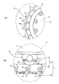
- FIG. 1 is a side view of a crawler-type traveling device for a hydraulic excavator equipped with a sprocket whose wear amount is measured by a wear amount measuring apparatus according to an embodiment of the present invention.
- (A) is the X section enlarged view in FIG.
- (B) is the Y section enlarged view.
- 1 is an overall external perspective view of a wear amount measuring apparatus according to an embodiment of the present invention.
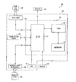
- 1 is a schematic system configuration diagram of a wear amount measuring apparatus according to an embodiment. The functional block diagram of an arithmetic circuit. The flowchart explaining an abrasion amount measurement program. Explanatory drawing (1) of the abrasion amount measurement procedure of a sprocket.
- a wear amount measuring apparatus, a wear amount measuring method, a wear amount measuring program, and a recording medium according to an embodiment of the present invention will be described with reference to the drawings.
- the present invention is applied to a wear amount measuring apparatus using a sprocket equipped in a crawler type traveling device of a hydraulic excavator as a work vehicle as a work amount measurement object.
- the present invention is not limited to this, and the present invention can also be applied to a wear amount measuring apparatus that uses other consumable parts as wear amount measurement objects.
- a track-type traveling device 1 shown in FIG. 1 is a track frame that extends in the front-rear direction on both sides of a center frame 3 having a mounting base 2 for a swing bearing (not shown) that supports an upper swing body (not shown) in a turnable manner. 4 (only the left side is shown).
- An idler (idling wheel) 5 is provided at the front end of the track frame 4.
- a sprocket (driving wheel) 6 is provided at the rear end of the track frame 4.
- a crawler belt 7 is wound in an elliptical shape between the idler 5 and the sprocket 6.
- the sprocket 6 is fastened by bolts 10 to a sprocket hub 9 that is rotationally driven by a traveling hydraulic motor 8.
- the sprocket 6 and some of the plurality of bolts 10 can be visually recognized from the outside.
- the sprocket 6 has a plurality of teeth 6 a that engage with the crawler belt 7 on the outer periphery. Then, the excavator is caused to travel by rotating the crawler belt 7 by the rotation. For this reason, the surface of the tooth part 6a engaged with the crawler belt 7 is subjected to a hardening process.
- the crawler belt 7 mainly includes a track link 13 in which a required link assembly 11 including a pair of left and right links is connected endlessly via a crawler belt pin 12, and each link assembly 11. And a crawler plate 15 fastened by a bolt 14 to the grounding surface side.
- 11a) is formed.
- the tread surface 11a can be visually recognized from the outside in a place where the tread surface 11a is not in contact with the lower rolling device 16.
- the wear amount measuring device 20 includes a measuring device main body 22 having necessary operation keys (KEYs) 21 for inputting characters, a display device (DISPLAY) 23 such as a liquid crystal display, and a display device. And a mouse (MOUSE) 24 for operating a mouse pointer displayed on the screen 23.
- KYs necessary operation keys
- DISPLAY display device
- MOUSE mouse
- the measurement apparatus main body 22 includes a DVD drive (DVD DRIVE) 25, a memory card interface (MEMORY CARD INTERFACE) 26, an arithmetic circuit 27, and a storage device drive (SOLID STATE DRIVE). 34 is incorporated.
- DVD DRIVE DVD drive
- MEMORY CARD INTERFACE memory card interface
- SOLID STATE DRIVE storage device drive
- the DVD drive 25 has a tray 25a (see FIG. 3) for inserting the DVD-ROM 28 into the apparatus, and reads data recorded on the DVD-ROM 28 inserted into the apparatus by the tray 25a.
- the DVD-ROM 28 stores design drawing data, a predetermined wear amount measurement program, and the like.
- the memory card interface 26 has a slot (not shown) into which the memory card 29 is inserted, and mediates data exchange between the memory card 29 inserted into the slot and the arithmetic circuit 27.
- digital data (hereinafter simply referred to as “actual image data”) of an image including the sprocket 6 and the bolt (reference portion) 10 taken by the digital camera 30 (see FIG. 3).
- actual image data digital data
- the sprocket 6 and the bolt 10 that are to be photographed are exposed to the outside. For this reason, it is possible to perform imaging in a state where the sprocket 6 is attached to the work vehicle (use state).
- the arithmetic circuit 27 mainly includes an I / O circuit 31, a CPU (Central Processing Unit) 32, and a memory 33.
- the I / O circuit 31 has a function of processing transmission / reception of signals between the CPU 32 and peripheral devices.
- the CPU 32 executes processing such as calculation in accordance with a predetermined wear force measurement program stored in the storage device drive 34.
- the memory 33 is a cache memory, and includes a storage element such as a read / write free RAM or a read-only ROM.
- the memory 33 stores data and the like that need to be temporarily stored in the calculation process.
- the storage device drive 34 is an external storage device using a semiconductor storage element and is called a flash memory drive.
- the storage device drive 34 stores real image data read from the memory card 29 via the memory card interface 26.
- the storage device drive 34 stores a predetermined wear amount measurement program and design drawing data read from the DVD-ROM 28 via the DVD drive 25.
- design drawing data (1) Cartesian coordinate system map showing the dimensions (curved shape) of the tooth portion 6a at the time of manufacturing the sprocket 6, or (2) the reference circle center point (rotation center) of the sprocket 6 (3) a map of position coordinates (reference points) of the center point of the bolt 10 when the sprocket 6 is fixed to the sprocket hub 9 by the bolt 10; (4) A map of the position coordinates of the apex of each corner in the hexagonal head of the bolt 10 is stored in association with the vehicle type number for each vehicle type of the work vehicle.
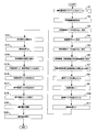
- the program stored in the storage device drive 34 includes a wear amount measurement program created according to the algorithm shown in the flowchart of FIG.
- the arithmetic circuit 27 has various functional units, that is, a data reading unit 41, that realize its function when the wear amount measurement program stored in the storage device drive 34 is executed by the CPU 32.
- a data holding unit 42 a display signal generating unit 43, an image processing unit 44, and a wear amount calculating unit 45.
- the data reading unit 41 reads necessary data from the storage device drive 34, from the DVD-ROM 28 via the DVD drive 25, and from the memory card 29 via the memory card interface 26.
- the data holding unit 42 holds necessary data in a state where processing such as machining is possible during execution of the wear amount measurement program.
- the data holding unit 42 corresponds to the memory 33 in FIG.
- the display signal generation unit 43 generates a predetermined display signal based on the data held in the data holding unit 42.
- the image processing unit 44 processes the image related data held in the data holding unit 42.
- the wear amount calculation unit 45 calculates the wear amount of the tooth portion 6 a of the sprocket 6 based on the data held in the data holding unit 42.
- step S1 Description of processing content of step S1> First, when the DVD-ROM 28 is placed on the tray 25a of the DVD drive 25 and the DVD-ROM 28 is inserted into the apparatus, the DVD drive 25 is activated.
- the data reading unit 41 reads the wear amount measurement program, design drawing data, and the like recorded in the DVD-ROM 28 via the DVD drive 25, and stores the read wear amount measurement program, design drawing data, and the like. Send to drive 34.
- the storage device drive 34 holds the wear amount measurement program, design drawing data, and the like sent from the data reading unit 41 in a program-executable state.
- the wear amount measurement program stored in the storage device drive 34 is executed by the CPU 32 via the data reading unit 41.
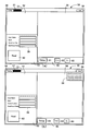
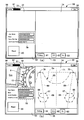
- the display signal generation unit 43 generates a display signal for displaying the image editing screen 50 shown in FIG. 7A on the display device 23, and sends the generated display signal to the display device 23. Send.
- the image editing screen 50 shown in FIG. 7A is displayed on the display device 23.
- the image editing screen 50 shown in FIG. 7A is a screen for image editing in the image editing mode, and includes a first screen region 51, a second screen region 52, and a third screen region 53. , A fourth screen area 54 and a fifth screen area 55 are provided.
- an image edit mode button 56 In the first screen area 51, an image edit mode button 56, a wear amount measurement mode button 57, a vehicle type number list button 58, and the like are displayed.
- the entire real image based on the real image data read from the memory card 29 is displayed.
- a basic input item entry field 59 for entering basic input items such as a user's name, vehicle type number, serial number, date of capturing actual image data, and an image data read start button 60 are displayed. Etc. are displayed.
- the main part real image copied and pasted by designating the area from the real image displayed in the second screen area 52 is different from the drawing image based on the design drawing data.
- a composite image superimposed and combined with a hierarchy is displayed.
- an alignment button 61 In the fifth screen area 55, an alignment button 61, an undo button 62, a redo button 63, and the like are displayed.
- Step S3 Description of Processing Contents of Step S3>
- the data read unit 41 reads the real image data stored in the memory card 29 via the memory card interface 26, and the storage device drive 34.
- the data is transmitted to the data holding unit 42.
- the data holding unit 42 holds the real image data sent from the data reading unit 41 in a state where processing such as processing is possible.
- the storage device drive 34 stores the transmitted real image data.
- ⁇ Vehicle model number list display step description of processing content of step S4>
- the data reading unit 41 reads the vehicle type number list data from the storage device drive 34 and transmits it to the data holding unit 42.
- the data holding unit 42 holds the vehicle model number list data sent from the data reading unit 41.
- the display signal generation unit 43 generates a display signal for displaying the vehicle type number list data held in the data holding unit 42 on the pull-down menu 64 as shown in FIG. 7B, and the generated display signal. Is transmitted to the display device 23. As a result, the vehicle model number list is displayed in the pull-down menu 64 shown in FIG.
- Step S5 Description of Processing Contents of Step S5>
- the data reading unit 41 displays the design drawing corresponding to the selected vehicle model number. Data is read from the storage device drive 34 and transmitted to the data holding unit 42.
- the data holding unit 42 holds the design drawing data sent from the data reading unit 41 in a state where processing such as processing is possible.
- the selected vehicle type number is automatically input into the vehicle type number entry column included in the basic input item entry column 59 of the third screen area 53.
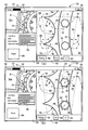
- the display signal generating unit 43 displays a real image GR0 based on the real image data held in the data holding unit 42 in the second screen area 52 as shown in FIG. 8B. Is transmitted to the display device 23. As a result, as shown in FIG. 8B, the real image GR0 based on the real image data is displayed in the second screen area 52.
- Display signal generating unit 43 a display signal for displaying the drawing image G D based on the design drawing data held in the data holding unit 42, the fourth screen region 54 as shown in FIG. 8 (b) Is transmitted to the display device 23.
- the fourth screen region 54 the drawing image G D based on the design drawing data is displayed in the diagram.
- Drawing image G D displayed on the fourth screen region 54 mainly includes a reference tooth profile lines 65, the standard bolt line 66, a bolt dots 67, and reference dot 68, the reference tooth top line 69, addendum A dot 70 and a tooth tip connecting line 71 are drawn.
- the reference tooth profile line 65 represents the outer shape of the two tooth portions 6a adjacent to each other.
- the reference bolt line 66 represents the outer shape of the hexagonal head of the two bolts 10 arranged so as to correspond to the two tooth portions 6a adjacent to each other.
- the bolt dot 67 represents each vertex of the hexagonal shape of the reference bolt line 66, and is represented by a dot having a diameter slightly larger than the line width of the reference bolt line 66.
- the reference dot 68 represents the center point of the bolt 10 and is represented by a dot having the same diameter as the bolt dot 67 at the hexagonal center position of the reference bolt line 66.
- the reference tooth tip line 69 is a line connecting the center of the reference circle of the tooth portion 6a of the sprocket 6, that is, the center of rotation of the sprocket 6 and the center point of the tip portion (tooth tip portion) of the tooth portion 6a.
- the tooth tip dot 70 represents the center point of the tooth tip portion, and is represented by a dot having the same diameter as the bolt dot 67.
- the tooth tip connecting line 71 is a line connecting two tooth tip dots 70 adjacent to each other.
- the user can move the display line on the fourth screen area 54 by dragging these dodds 67, 68 and 70 by operating the mouse 24.
- the main part real image G R1 that is copied by designating the area Z (see FIG. 9A) from the real image G R0 displayed in the second screen area 52 is the fourth screen area. 54.
- the image processing unit 44 extracts a main part real image data corresponding the real image data held in the data holding unit 42 to the main part real image G R1, and transmits the data holding unit 42.
- the data holding unit 42 holds main part real image data sent from the image processing unit 44 in a state where processing such as processing is possible.
- Display signal generating unit 43 a main part real image G R1 based on the main part real image data held in the data holding unit 42, for display on the fourth screen region 54 as shown FIG. 9 (a)
- the display signal is generated and transmitted to the display device 23.
- the fourth screen region 54 the composite image is displayed main part real image G R1 based on the main part real image data is superimposed with the drawings image G D
- the positional relationship between the main part real image G R1 and drawings image G D is not yet supported.
- the main part real image G R1 and drawings image G D in the composite image, which is another Layer it is possible to separate image processing.
- Step (1) Description of Processing Contents of Step S8>
- the mouse 24 moves on the fourth screen region 54, the two reference dots 68 of the drawings image G D, near the center point of the head of the two adjacent bolts 10 of each main part real image G R1
- a mouse pointer that is linked to the operation of the mouse 24 is displayed on the fourth screen area 54, and using this mouse pointer, the reference dot 68 is moved over the head of the bolt 10 in the main part real image GR1. Drag to.
- the image processing unit 44 causes the reference dot 68 and the reference bolt held in the data holding unit 42 so that the reference bolt line 66 and the bolt dot 67 move together with the operation of the mouse 24 together with the reference dot 68.
- the design drawing data regarding the line 66 and the bolt dot 67 is processed.
- the design drawing data relating to the reference dot 68, the reference bolt line 66, and the bolt dot 67 before processing is not displayed as an image but is separately held in the data holding unit 42.
- Display signal generating unit 43 the drawing image G D based on the design drawing data processed by the image processing unit 44 is performed to generate a display signal to be displayed on the fourth screen region 54, and transmits to the display device 23.
- This is moved shown as being two reference dots 68 in the vicinity of the center point of the head of the two bolts 10 adjacent the main part real image G R1 respectively in the drawing image G D in FIG. 9 (b) .
- two standard bolt line 66 of the drawing image G D is moved in the vicinity of the head of the two adjacent bolts 10 of each main part real image G R1, bolt following the respective standard bolt line 66
- the dots 67 are also moved.
- Step (1) Description of Processing Contents of Step S9>
- the image processing unit 44 sets the second reference dot 68 before and after the movement. based on the deviation of the position on the fourth screen region 54, and the position and size of the sprocket 6 which is indicated by reference image G D, and the position and size of the sprocket 6 which is displayed on the main part real image G R1 of Calculate the amount of deviation.
- the image processing unit 44 processes the main part real image data held in the data holding unit 42 and updates it as new main part real image data.
- the display signal generation unit 43 generates a display signal for displaying a new main part real image GR1 in the fourth screen area 54 based on the updated main part real image data, and transmits the display signal to the display device 23. To do. At the same time, drawing the image G D are reference dots 68 are displayed based on the design drawing data of the data related to the standard bolt line 66 and a bolt dot 67 is replaced with unprocessed data. Thus, as shown in FIG. 10 (a), a main part real image G R1 based on the updated main part real image data, a new composite image of the drawing image G D in the fourth screen region 54 Is displayed.
- reference bolt line 66 is displayed as a line connecting six bolt dots 67.
- the image processing unit 44 increases the size of the reference bolt line 66.
- the design drawing data held in the data holding unit 42 is processed so that the length changes in conjunction with the operation of the mouse 24.
- Display signal generating unit 43 generates a display signal for displaying the drawing image G D based on the design drawing data processed by the image processing unit 44 is applied to the fourth screen region 54, the display device 23 Send.
- the size of the reference bolt line 66 displayed in the fourth screen area 54 can be changed in conjunction with the operation of the mouse 24, so that the reference bolt line 66 can be easily enlarged or reduced. it can.
- Display signal generating unit generates a display signal for displaying the drawing image G D based by the image processing unit 44 to the design drawing data processing is performed on the fourth screen region 54, and transmits to the display device 23.
- the reference bolt line 66 displayed in the fourth screen area 54 can be rotated around the reference dot 68 in conjunction with the operation of the mouse 24, so that the reference bolt line 66 can be easily rotated. Can do.
- Step (2) Description of Processing Contents of Step S10>
- the center point of the two bolts 10 in the main part real image G R1 and the two reference dots 68 of the drawing image G D are more accurately matched.
- the two reference dots 68 are moved more accurately to the center points of the two bolts 10 in the main part real image GR1 .
- the user repeats the above-described enlargement / reduction operation and rotation operation of the reference bolt line 66 (see FIG. 10A), and as shown in FIG. 10B, in the main part real image GR1 .
- the two reference bolt lines 66 are completely aligned with the outlines of the heads of the two bolts 10. This makes it possible to the two reference dots 68 in the drawing image G D, is precisely coincident with the center point of the head of the two bolts 10 adjacent the main part real image G R1.
- the rotation angle does not match. Therefore, the outline of the tooth portion 6a of the sprocket 6 in the reference tooth profile line 65 and the main part real image G R1 in the drawing image G D do not correspond.
- Step (2) Description of Processing Contents of Step S11> After the center point of the two bolts 10 at the main part real image G R1 in alignment process of the reference dot 68 (2), and the two reference dots 68 of the drawings image G D are matched accurately matching button 61 When pressed, the image processing unit 44, such that the main part real image G R1 and drawings image G D are equal scales, by processing the main part real image data held in the data holding unit 42, a new Update as main part real image data.
- the display signal generation unit 43 generates a display signal for displaying a new main part real image GR1 in the fourth screen area 54 based on the updated main part real image data, and transmits the display signal to the display device 23. To do. Thus, as shown in FIG. 10 (b), a new synthetic image combined by the main part real image G R1 and scale are equal drawing image G D is displayed on the fourth screen region 54.
- the tooth portion 6a of the sprocket 6 and the bolt 10 have different rotationally symmetric phases with respect to the center point of the reference circle (the tooth portion is symmetric 24 times and the bolt is 18 times symmetric).
- the screens shown in FIGS. 10A and 10B appear, but when the phases match (for example, both the tooth and bolt are symmetric 24 times), the drawing image G is displayed at this stage.
- D and the main part real image GR1 can be made to substantially correspond to each other. In this case, the screen display immediately shifts from FIG. 9B to FIG. 11A.
- the drawing image G D and main part real image G R1 the synthesized and displayed on the same screen position of the two adjacent bolts 10 (reference point) in a state of being matched as a reference unit, both the position of -It can be displayed in a state corresponding to the size.
- ⁇ Tooth tip positioning process description of processing content of step S12>
- the image processing unit 44 holds the data holding unit 42 so that the reference tooth profile line 65 rotates with the rotation center of the sprocket 6 as a reference.
- the design drawing data relating to the reference tooth profile line 65 is processed (see FIG. 11A).
- Display signal generating unit 43 based on the image processing unit 44 to the design drawing data processing is performed, to generate a display signal for displaying the drawing image G D in the fourth screen region 54, the display device 23 Send to.
- the reference tooth profile line 65 displayed in the fourth screen area 54 can be rotated with the rotation center of the sprocket 6 as a reference in conjunction with the operation of the mouse 24. Therefore, the reference tooth profile line 65 can be easily rotated. It can be carried out.
- the rotational operation of the reference tooth profile line 65 is aligned with the reference tooth profile line 65 to the tooth portion 6a of the sprocket 6 in main part real image G R1, the rotation angle and the reference tooth profile line 65 of the sprocket 6 in main part real image G R1 Match the rotation angle.
- the tooth tip connecting line 71 is displayed by a virtual line.
- Step (3) Description of Processing Contents of Step S13>
- the alignment button 61 is pressed, the image processing unit 44 , such that the rotation angle and the reference tooth profile line 65 are equal to each other in the sprocket 6 and drawings image G D in the main part real image G R1, by processing the main part real image data held in the data holding unit 42, Update as new main part real image data.
- the display signal generation unit 43 generates a display signal for displaying a new main part real image GR1 in the fourth screen area 54 based on the updated main part real image data, and transmits the display signal to the display device 23.
- FIG. 11 as shown in (b), the main part real image G new synthesized image and the reference tooth profile line 65 was synthesized in one another equal rotation angle at the sprocket 6 and drawings image G D in R1 is 4 Are displayed in the screen area 54.
- step S13 when the process of step S13 is completed, the process proceeds to the next step S14. However, if the process returns to step S8 and steps S8 to S13 are repeated, the measurement accuracy can be further improved. .
- ⁇ Abrasion amount measurement screen display step description of processing content of step S14>
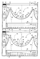
- the display signal generation unit 43 When the wear amount measurement mode button 57 is clicked by operating the mouse 24, the display signal generation unit 43 generates a display signal for causing the display device 23 to display the wear amount measurement screen 75 shown in FIG. Then, the data is transmitted to the display device 23. Thereby, the wear amount measurement screen 75 shown in FIG. 12A is displayed on the display device 23.
- the wear amount measurement screen 75 shown in FIG. 12A is a screen for image editing in the wear amount measurement mode, and includes a sixth screen region 76, a seventh screen region 77, and an eighth screen. A region 78 is included.
- a measurement result saving button 79 In the sixth screen area 76, a measurement result saving button 79, an undo button 80, a redo button 81, and the like are displayed.
- step S13 image processing step (3)
- a graph 82 showing the measurement result of the wear amount is displayed.
- ⁇ Display Step of Position Setting Dots 83 and Curvature Setting Dots 84 Explanation of Processing Contents of Step S15>
- a plurality of position setting dots 83 and curvature setting dots 84 are alternately displayed on the reference tooth profile line 65.
- the positions of the dots 83 and 84 can be moved to arbitrary positions by the user's operation of the mouse 24.
- Step S16 Description of Processing Contents of Step S16>
- the image processing unit 44 does not change the curvature between the two adjacent curvature setting dots 84, and corrects only the position, so that the data holding unit 42.
- the design drawing data held in the machine is processed.
- Display signal generating unit 43 based on the image processing unit 44 to the design drawing data processing is performed, to generate a display signal for displaying the drawing image G D in the screen region 77 of the seventh display device 23 Send to. Thereby, only the position of the position setting dot 83 is corrected and displayed without changing the curvature between the two adjacent curvature setting dots 84.
- ⁇ Curvature setting dot alignment step description of processing content of step S17>
- the image processing unit 44 corrects the curvature of the reference tooth profile line 65 between two adjacent position setting dots 83 corresponding to the dragged position.
- the design drawing data held in the data holding unit 42 is processed.
- Display signal generating unit 43 based on the image processing unit 44 to the design drawing data processing is performed, to generate a display signal for displaying the drawing image G D in the screen region 77 of the seventh display device 23 Send to. Thereby, the curvature of the reference tooth profile line 65 between two adjacent position setting dots 83 is corrected and displayed.
- the wear amount calculation unit 45 is based on the amount of movement from the reference tooth profile line 65 to the corresponding correction tooth profile line 85, in other words, based on the size of the interval between the correction tooth profile line 85 and the reference tooth profile line 65.
- the amount of wear of the tooth portion 6a is calculated. Data relating to the calculated wear amount is held in the data holding unit 42.
- ⁇ Abrasion amount display step description of processing content of step S20>
- the display signal generation unit 43 generates a display signal for displaying the graph 82 in the eighth screen area 78 based on the data regarding the wear amount held in the data holding unit 42 and transmits the display signal to the display device 23. To do.
- a graph 82 is displayed in the eighth screen area 78, where the vertical axis indicates the amount of wear of the tooth portion 6a of the sprocket 6 and the horizontal axis indicates the position where the reference tooth profile line 65 is linearly developed.
- a specific numerical value indicates which part of the tooth portion 6a of the sprocket 6 is worn, and a wear limit line 86 indicating a wear limit amount that the sprocket 6 should be replaced is displayed.
- the sprocket 6 corresponds to the “wear amount measurement object” of the present invention.
- the outline of the tooth tip of the sprocket 6 corresponds to the “wear amount measurement object” of the present invention.
- the center point of the bolt 10 corresponds to the “measurement positioning reference” of the present invention.
- the bolt 10 corresponds to the “reference part” of the present invention.
- two adjacent bolts are used as the reference portion, but three or more adjacent bolts may be used.
- the center points of the two bolts 10 adjacent to each other are used as a reference for positioning the sprocket 6 in measurement. These two center points correspond to “reference points” of the present invention. Two bolts 10 adjacent to each other are used as a reference portion corresponding to these references.
- the rotation angle of the sprocket 6 is further used as a positioning reference for measurement, and the tooth tip portion of the tooth portion 6a of the sprocket 6 is used as a reference portion.
- the configuration including the display device 23 and the display signal generation unit 43 corresponds to the “image display means” of the present invention.
- the image processing unit 44 corresponds to the “image processing means” of the present invention.
- the wear amount calculator 45 corresponds to the “wear amount calculator” of the present invention.
- the reference tooth profile line 65 corresponds to the “drawing outline” of the present invention.
- the modified tooth profile line 85 corresponds to the “measurement outline” of the present invention.
- the wear amount measurement program created according to the algorithm shown in the flowchart of Fig. 6 corresponds to the "program" of the present invention.
- the DVD-ROM 28 corresponds to the “recording medium” of the present invention.
- the wear amount measuring device, the wear amount measuring method, the program, and the recording medium of the present invention have been described based on one embodiment, but the present invention is not limited to the configuration described in the above embodiment, The configuration can be changed as appropriate without departing from the spirit of the invention.
- the wear amount of the tread surface 11a of the link assembly 11 may be measured.
- the link assembly 11 since the link assembly 11 can be photographed from the outside while being mounted on the work vehicle, real image data can be easily obtained.
- the positioning reference for measurement is the center point of the pair of crawler belt pins 12 adjacent to each other in the side view (viewpoint as shown in FIG. 2B), and the reference portion for defining the reference is A pair of crawler belt pins 12.
- the absolute value of the wear amount of the tread 11a can be measured.
- the front end / rear end of the tread surface 11a may be used as a positioning reference / reference portion for measurement.
- the difference in the relative wear amount on the tread surface 11a is measured.
- it since it is the wear unevenness on the tread surface 11a that determines the component life of the link, it is based on the relative wear amount on the tread surface 11a. To determine the replacement time.
- the tread surface 11a of the link assembly 11 is indicated by a line having three valleys in a side view according to the use state, and the depth of the central valley is If it exceeds the predetermined value, it may be determined that it is time for replacement.
- the wear amount measuring device, the wear amount measuring method, the wear amount measuring program and the recording medium of the present invention are suitably used for measuring the wear amount of a consumable part having a complicated shape and a different progress of wear depending on the part. Can do.
Landscapes
- Physics & Mathematics (AREA)
- General Physics & Mathematics (AREA)
- Length Measuring Devices By Optical Means (AREA)
- Image Processing (AREA)
Abstract
Description
手順(1):これから摩耗量を測定しようとする実物のスプロケットの歯部に透明フィルムを押し当て、透明フィルムを通して見える実物のスプロケットの歯部の外形に沿って油性マーカ等のペンを走らせる。これにより、フィルム上に実物のスプロケットの歯部の外形形状を転写する。
実物のスプロケットの歯部を透明フィルムに転写する作業(手順(1))が面倒である。
また、作業者の目視では、交換時期の判断に、ばらつきが避けられない。
投光器は、車輪の側面に刻まれた溝に対し斜めにスリット光を投光する。
第1の画像処理装置は、第1のCCDカメラの画像から車輪の外形の座標を計測する。
コンピュータは、第1の画像処理装置による車輪の外形の座標データや、第2の画像処理装置による車輪の溝の位置データ、リニアスケールによる車輪のフランジ高さの計測データなどに基づいて所定の演算処理を実行する。
摩耗量測定対象物とその摩耗量測定対象物の測定上の位置決めの基準となる基準部とを含む実物画像データに基づいて実物画像を表示するとともに、前記摩耗量測定対象物とその基準部とを含む設計図面データに基づいて図面画像を表示する画像表示手段と、
前記実物画像における前記基準部と前記図面画像における前記基準部とを一致させた際に、前記実物画像と前記図面画像とを対応する位置関係で等しい尺度で重ね合わせる画像処理を実施する画像処理手段と、
前記実物画像における摩耗量測定対象物の外形に沿って描かれた測定用外形線と前記図面画像における図面外形線との間隔の大きさに基づいて摩耗量を演算する摩耗量演算手段と、
を備えている。
摩耗量測定対象物とその摩耗量測定対象物の測定上の位置決めの基準となる基準部とを含む実物画像データに基づいて実物画像を表示するとともに、前記摩耗量測定対象物とその基準部とを含む設計図面データに基づいて図面画像を表示する画像表示工程と、
前記実物画像における前記基準部と前記図面画像における前記基準部とを一致させた際に、前記実物画像と前記図面画像とを対応する位置関係で等しい尺度で重ね合わせる画像処理を実施する画像処理工程と、
前記実物画像における摩耗量測定対象物の外形に沿って描かれた測定用外形線と前記図面画像における図面外形線との間隔の大きさに基づいて摩耗量を演算する摩耗量演算工程と、
を含む。
摩耗量測定対象物とその摩耗量測定対象物の測定上の位置決めの基準となる2つの基準点からなる基準部とを含む実物画像データに基づいて実物画像を表示するとともに、前記摩耗量測定対象物とその2つの基準点からなる基準部とを含む設計図面データに基づいて図面画像を表示するステップと、
前記実物画像における前記基準部と前記図面画像における前記基準部とを一致させた際に、前記実物画像と前記図面画像とを対応する位置関係で等しい尺度で重ね合わせる画像処理を実施するステップと、
前記実物画像における摩耗量測定対象物の外形に沿って描かれた測定用外形線と前記図面画像における図面外形線との間隔の大きさに基づいて摩耗量を演算するステップと、
を備えた摩耗量測定方法をコンピュータに実行させる。
摩耗量測定対象物とその摩耗量測定対象物の測定上の位置決めの基準となる複数の基準点からなる基準部とを含む実物画像データに基づいて実物画像を表示するとともに、前記摩耗量測定対象物とその複数の基準点からなる基準部とを含む設計図面データに基づいて図面画像を表示する画像表示ステップと、
前記実物画像における前記基準部と前記図面画像における前記基準部とを一致させた際に、前記実物画像と前記図面画像とを対応する位置関係で等しい尺度で重ね合わせる画像処理を実施する画像処理ステップと、
前記実物画像における摩耗量測定対象物の外形に沿って描かれた測定用外形線と前記図面画像における図面外形線との間隔の大きさに基づいて摩耗量を演算する摩耗量演算ステップと、
を備えた摩耗量測定方法をコンピュータに実行させる摩耗量測定プログラムを記録したコンピュータ読み取り可能な記録媒体である。
図1に示される履帯式走行装置1は、上部旋回体(図示省略)を旋回可能に支持する旋回ベアリング(図示省略)の取付台2を有するセンタフレーム3の両側においてそれぞれ前後方向に延びるトラックフレーム4(左側のみ図示)を備えている。
図3に示されるように、摩耗量測定装置20は、文字等を入力する所要の操作キー(KEY)21を有する測定装置本体22と、液晶ディスプレイ等の表示装置(DISPLAY)23と、表示装置23の画面上に表示されるマウスポインタ等を操作するマウス(MOUSE)24とを備えている。
図4に示されるように、測定装置本体22の内部には、DVDドライブ(DVD DRIVE)25と、メモリカードインタフェース(MEMORY CARD INTERFACE)26と、演算回路27と、記憶装置ドライブ(SOLID STATE DRIVE)34とが組み込まれている。
DVDドライブ25は、DVD-ROM28を装置内に挿入するためのトレー25a(図3参照)を有し、トレー25aによって装置内に挿入されるDVD-ROM28に記録されたデータを読み出す。
メモリカードインタフェース26は、メモリカード29が挿入される図示されないスロットを有し、スロットに挿入されたメモリカード29と演算回路27との間のデータのやり取りを仲介する。
演算回路27は、主として、I/O回路31と、CPU(中央処理装置)32と、メモリ33とにより構成されている。
記憶装置ドライブ34は、半導体記憶素子を用いた外部記憶装置で、フラッシュメモリドライブと呼ばれる。
記憶装置ドライブ34には、メモリカードインタフェース26を介して、メモリカード29から読み出した実物画像データが記憶される。
図5に示されるように、演算回路27は、記憶装置ドライブ34に記憶される摩耗量測定プログラムがCPU32によって実行されることによって、その機能が実現される各種機能部、すなわち、データ読み出し部41と、データ保持部42と、表示信号生成部43と、画像処理部44と、摩耗量演算部45と、を備えている。
摩耗量演算部45は、データ保持部42に保持されているデータに基づいて、スプロケット6の歯部6aの摩耗量を演算する。
次に、本実施形態の摩耗量測定装置20を用いた摩耗量測定方法の具体的な実施の手順について、図5の演算回路の機能ブロック図や、図6のフローチャート、図7~図12のスプロケットの摩耗量測定手順の説明図を用いて以下に説明する。
まず、DVDドライブ25のトレー25aにDVD-ROM28が置かれ、装置内にDVD-ROM28が挿入されると、DVDドライブ25が起動する。
次に、記憶装置ドライブ34に記憶された摩耗量測定プログラムが、データ読み出し部41を経由してCPU32によって実行される。具体的には、まず、表示信号生成部43が、図7(a)に示される画像編集画面50を表示装置23に表示させるための表示信号を生成し、生成した表示信号を表示装置23へ送信する。これにより、図7(a)に示される画像編集画面50が表示装置23に表示される。
ここで、図7(a)に示される画像編集画面50は、画像編集モードにおける画像編集用の画面であって、第1の画面領域51、第2の画面領域52、第3の画面領域53、第4の画面領域54、第5の画面領域55を有している。
マウス24の操作により画像データ読み出し開始ボタン60がクリックされると、データ読み出し部41は、メモリカードインタフェース26を介してメモリカード29に記憶されている実物画像データを読み出して、記憶装置ドライブ34とデータ保持部42とへ送信する。データ保持部42は、データ読み出し部41から送られた実物画像データを加工等の処理が可能な状態で保持する。記憶装置ドライブ34は、送信された実物画像データを記憶する。
マウス24の操作により車種番号リストボタン58がクリックされると、データ読み出し部41は、記憶装置ドライブ34から車種番号リストデータを読み出して、データ保持部42へ送信する。データ保持部42は、データ読み出し部41から送られた車種番号リストデータを保持する。
プルダウンメニュー64に表示された車種番号リストの中から、マウス24の操作により、実物画像データに対応する車種番号がクリックされると、データ読み出し部41は、選択された車種番号に対応する設計図面データを記憶装置ドライブ34から読み出して、データ保持部42へ送信する。データ保持部42は、データ読み出し部41から送られた設計図面データを加工等の処理が可能な状態で保持する。このとき、図8(a)に示されるように、第3の画面領域53の基本入力事項記入欄59に含まれる車種番号記入欄には、選択された車種番号が自動的に入力される。
表示信号生成部43は、データ保持部42に保持されている実物画像データに基づく実物画像GR0を、図8(b)に示されるように第2の画面領域52に表示させるための表示信号を生成して、表示装置23へ送信する。これにより、図8(b)に示されるように、第2の画面領域52には、実物画像データに基づく実物画像GR0が表示される。
第4の画面領域54に表示される図面画像GDは、主に、基準歯形ライン65と、基準ボルトライン66と、ボルトドット67と、基準ドット68と、基準歯先ライン69と、歯先ドット70と、歯先結合ライン71と、によって描かれている。
基準ボルトライン66は、互いに隣接する2つの歯部6aに対応するように配置される2つのボルト10の六角形状の頭部の外形を表す。
ユーザは、これらドッド67,68,70をマウス24の操作によりドラッグすると、表示のラインを第4の画面領域54上で移動させることができる。
マウス24の操作により、第2の画面領域52に表示されている実物画像GR0から領域Z(図9(a)参照)を指定してコピーした要部実物画像GR1が第4の画面領域54に貼り付けられる。このとき、画像処理部44は、データ保持部42に保持されている実物画像データから要部実物画像GR1に対応する要部実物画像データを抽出して、データ保持部42に送信する。データ保持部42は、画像処理部44から送られた要部実物画像データを加工等の処理が可能な状態で保持する。
ここで、要部実物画像GR1としては、スプロケット6の互いに隣接する歯部6aと、これら歯部6aに対応する2つの固定用のボルト10の頭部とを含む領域が映し出されている必要がある。したがって、ステップS7の処理に際して、第2の画面領域52に表示された実物画像GR0におけるスプロケット6の互いに隣接する歯部6aと、これら歯部6aに対応する2つの固定用のボルト10の頭部とを含む領域Z(図9(a)参照)とを、マウス24の操作により指定してコピーする必要がある。
マウス24の操作により、第4の画面領域54上で、図面画像GDの2つの基準ドット68を、それぞれ要部実物画像GR1の隣接する2つのボルト10の頭部の中心点付近に移動させる。具体的には、第4の画面領域54上にマウス24の操作に連動するマウスポインタが表示され、このマウスポインタを用いて、基準ドット68を要部実物画像GR1のボルト10の頭部上にドラッグする。すると、画像処理部44は、基準ドット68と共に基準ボルトライン66およびボルトドット67がそれぞれマウス24の操作に連動して移動するように、データ保持部42に保持されている基準ドット68、基準ボルトライン66およびボルトドット67に関する設計図面データを加工する。加工前(すなわち、基準ドット68移動前)の基準ドット68、基準ボルトライン66およびボルトドット67に関する設計図面データは、画像としては表示されず、別途、データ保持部42に保持される。
基準ドット68の位置合せ工程(1)において2つの基準ドット68の移動が完了した後、整合ボタン61が押されると、画像処理部44は、移動前・後のそれぞれ2つの基準ドット68の第4の画面領域54上の位置のずれに基づいて、図面画像GDで表示されているスプロケット6の位置・大きさと、要部実物画像GR1で表示されているスプロケット6の位置・大きさとのずれの量を演算する。そして、このずれの量に基づいて、要部実物画面GR1で表示されているスプロケット6の位置と大きさを、図面画像GDのスプロケット6の位置と大きさに変換する変換係数を演算する。そして、画像処理部44は、算出された変換係数に基づいて、データ保持部42に保持されている要部実物画像データを加工して、新しい要部実物画像データとして更新する。
ところで、基準ボルトライン66は、6つのボルトドット67を結ぶラインとして表示されている。ここで、マウス24の操作によって、ボルトドット67をボルト径方向に沿って基準ドット68に向かう方向に、あるいは基準ドット68から離れる方向にドラッグすると、画像処理部44は、基準ボルトライン66の大きさがマウス24の操作に連動して変化するように、データ保持部42に保持されている設計図面データを加工する。
第4の画面領域54において、要部実物画像GR1における2つのボルト10の中心点と、図面画像GDの2つの基準ドット68とをより正確に一致させるため、マウス24の操作によって、2つの基準ドット68をより正確に要部実物画像GR1における2つのボルト10の中心点に移動させる。
基準ドット68の位置合せ工程(2)において要部実物画像GR1における2つのボルト10の中心点と、図面画像GDの2つの基準ドット68とが正確に一致された後、整合ボタン61が押されると、画像処理部44は、要部実物画像GR1と図面画像GDとが等しい尺度となるように、データ保持部42に保持されている要部実物画像データを加工して、新しい要部実物画像データとして更新する。
マウス24の操作により、歯先ドット70をスプロケット6の周方向にドラッグすると、画像処理部44は、基準歯形ライン65がスプロケット6の回転中心を基準として回転するように、データ保持部42に保持されている基準歯形ライン65に関する設計図面データを加工する(図11(a)参照)。
歯先部の位置合せ工程において要部実物画像GR1におけるスプロケット6の回転角と基準歯形ライン65の回転角とを正確に一致させた後、整合ボタン61が押されると、画像処理部44は、要部実物画像GR1におけるスプロケット6と図面画像GDにおける基準歯形ライン65とが互いに等しい回転角となるように、データ保持部42に保持されている要部実物画像データを加工して、新しい要部実物画像データとして更新する。
なお、本実施形態では、ステップS13の処理が終われば、その後、次のステップS14に移るが、更にステップS8に戻り、ステップS8~ステップS13を繰り返し行うと、より計測の精度を高めることができる。
マウス24の操作によって摩耗量測定モードボタン57がクリックされると、表示信号生成部43は、図12(a)に示される摩耗量測定画面75を表示装置23に表示させるための表示信号を生成して、表示装置23へ送信する。これにより、図12(a)に示される摩耗量測定画面75が表示装置23に表示される。
ここで、図12(a)に示される摩耗量測定画面75は、摩耗量測定モードにおける画像編集用の画面であって、第6の画面領域76、第7の画面領域77、第8の画面領域78を有している。
ここでは、基準歯形ライン65上に複数の位置設定ドット83と曲率設定ドット84とを交互に表示させる。各ドット83,84の位置は、ユーザのマウス24の操作により任意の位置に移動させることができる。
位置設定ドット83がマウス24の操作によってドラッグされると、画像処理部44は、隣接する2つの曲率設定ドット84の間で曲率を変更せず、位置のみを修正するように、データ保持部42に保持されている設計図面データを加工する。
曲率設定ドット84がマウス24の操作によってドラッグされると、画像処理部44は、そのドラッグされた位置に対応して隣接する2つの位置設定ドット83の間の基準歯形ライン65の曲率を修正するように、データ保持部42に保持されている設計図面データを加工する。
マウス24の操作によって、各位置設定ドット83が要部実物画像GR1の歯形ライン上に移動し、次いで、各曲率設定ドット84が要部実物画像GR1の歯形ライン上に移動すると、図12(b)に示されるように、第7の画面領域77に表示されている基準歯形ライン65を、要部実物画像GR1の歯形ラインに一致させることができる。ここで、一致させた歯形ラインを修正歯形ライン85とする。この修正歯形ライン85に関するデータは、データ保持部42に保持される。
摩耗量演算部45は、基準歯形ライン65から対応する修正歯形ライン85までの移動量に基づいて、言い換えれば、修正歯形ライン85と基準歯形ライン65との間隔の大きさに基づいて、スプロケット6の歯部6aの摩耗量を演算する。そして、算出された摩耗量に関するデータは、データ保持部42に保持される。
表示信号生成部43は、データ保持部42に保持されている摩耗量に関するデータに基づいて、グラフ82を第8の画面領域78に表示させるための表示信号を生成して、表示装置23へ送信する。これにより、第8の画面領域78に、縦軸がスプロケット6の歯部6aの摩耗量、横軸が基準歯形ライン65を直線状に展開した位置を示すグラフ82が表示される。なお、グラフ82においては、スプロケット6の歯部6aのどの部位がどれくらい摩耗しているかが具体的な数値で示されるとともに、スプロケット6の交換が望ましい摩耗限界量を示す摩耗限界ライン86が表示される。
本実施形態の摩耗量測定装置20によれば、スプロケット6の歯部6aのような複雑な曲線形状のどの部位がどれくらい摩耗しているかを、図12(b)のグラフ82によって形状全域に亘って正確に求めることができる。よって、スプロケット6の歯部6aの摩耗量が、所定の摩耗限界を超えたか否かを容易に確認することができる。
スプロケット6が、本発明の「摩耗量測定対象物」に対応する。また、画像では、スプロケット6の歯先の外形線が、本発明の「摩耗量測定対象物」に対応する。
ボルト10が、本発明の「基準部」に対応する。本実施形態では、隣接する2箇所のボルトを基準部としたが、隣接する3箇所以上のボルトであってもよい。
摩耗量演算部45が、本発明の「摩耗量演算手段」に対応する。
修正歯形ライン85が、本発明の「測定用外形線」に対応する。
以上、本発明の摩耗量測定装置、摩耗量測定方法、プログラムおよび記録媒体について、一実施形態に基づいて説明したが、本発明は上記実施形態に記載した構成に限定されるものではなく、その趣旨を逸脱しない範囲において適宜その構成を変更することができるものである。
上記実施形態においては、摩耗量測定対象物としてスプロケット6を用い、このスプロケット6の歯部6aの摩耗量を測定する例を示したが、本発明はこれに限定されるものではない。例えば、摩耗量測定対象物として、図2(b)に示されるリンクアッセンブリ11を用いてもよい。
これにより、上述した実施形態のスプロケット6と同様に、リンクアッセンブリ11を作業車両に搭載された状態で外部から撮影することができるため、容易に実物画像データを得ることができる。
9 スプロケットハブ
10 ボルト(基準部)
11 リンクアッセンブリ(摩耗量測定対象物)
12 履帯ピン(基準部)
20 摩耗量測定装置
23 表示装置(画像表示手段)
28 DVD-ROM(記録媒体)
43 表示信号生成部(画像表示手段)
44 画像処理部(画像処理手段)
45 摩耗量演算部(摩耗量演算手段)
65 基準歯形ライン(図面外形線)
85 修正歯形ライン(測定用外形線)
Claims (9)
- 摩耗量測定対象物とその摩耗量測定対象物の測定上の位置決めの基準となる基準部とを含む実物画像データに基づいて実物画像を表示するとともに、前記摩耗量測定対象物とその基準部とを含む設計図面データに基づいて図面画像を表示する画像表示手段と、
前記実物画像における前記基準部と前記図面画像における前記基準部とを一致させた際に、前記実物画像と前記図面画像とを対応する位置関係で等しい尺度で重ね合わせる画像処理を実施する画像処理手段と、
前記実物画像における摩耗量測定対象物の外形に沿って描かれた測定用外形線と前記図面画像における図面外形線との間隔の大きさに基づいて摩耗量を演算する摩耗量演算手段と、
を備える摩耗量測定装置。 - 前記摩耗量測定対象物は、外周部に複数の歯部を有するスプロケットであり、
前記基準部は、前記スプロケットをその取付相手であるスプロケットハブに締結する少なくとも2個のボルトである、
請求項1に記載の摩耗量測定装置。 - 前記摩耗量測定対象物は、外周部に複数の歯部を有するスプロケットであり、
前記基準部は、前記スプロケットをその取付相手であるスプロケットハブに締結する2個のボルトと、前記スプロケットの歯先部とである、
請求項1に記載の摩耗量測定装置。 - 摩耗量測定対象物とその摩耗量測定対象物の測定上の位置決めの基準となる基準部とを含む実物画像データに基づいて実物画像を表示するとともに、前記摩耗量測定対象物とその基準部とを含む設計図面データに基づいて図面画像を表示する画像表示工程と、
前記実物画像における前記基準部と前記図面画像における前記基準部とを一致させた際に、前記実物画像と前記図面画像とを対応する位置関係で等しい尺度で重ね合わせる画像処理を実施する画像処理工程と、
前記実物画像における摩耗量測定対象物の外形に沿って描かれた測定用外形線と前記図面画像における図面外形線との間隔の大きさに基づいて摩耗量を演算する摩耗量演算工程と、
を含む摩耗量測定方法。 - 前記基準部は、摩耗量測定対象物の使用状態で視認可能な離間した複数の基準点である、
請求項4に記載の摩耗量測定方法。 - 前記画像処理工程は、
前記実物画像の前記複数の基準点に設計画像の複数の基準点をそれぞれ一致させた画像を表示する工程と、
前記工程で表示される設計画像の複数の基準点と前記画像表示工程で表示される設計画像の複数の基準点のずれに基づいて、前記画像表示工程で表示された前記実物画像を前記画像表示工程で表示された前記図面画像に対応する位置関係で等しい尺度に変換する変換する工程と、
前記変換された実物画像を前記図面画像に重ね合わせて表示する工程と、
を含む、
請求項5に記載の摩耗量測定方法。 - 摩耗量測定対象物とその摩耗量測定対象物の測定上の位置決めの基準となる複数の基準点からなる基準部とを含む実物画像データに基づいて実物画像を表示するとともに、前記摩耗量測定対象物とその複数の基準点からなる基準部とを含む設計図面データに基づいて図面画像を表示する画像表示ステップと、
前記実物画像における前記基準部と前記図面画像における前記基準部とを一致させた際に、前記実物画像と前記図面画像とを対応する位置関係で等しい尺度で重ね合わせる画像処理を実施する画像処理ステップと、
前記実物画像における摩耗量測定対象物の外形に沿って描かれた測定用外形線と前記図面画像における図面外形線との間隔の大きさに基づいて摩耗量を演算する摩耗量演算ステップと、
を備えた摩耗量測定方法をコンピュータに実行させる摩耗量測定プログラム。 - 前記画像処理ステップは、
前記実物画像の前記複数の基準点に設計画像の複数の基準点をそれぞれ一致させた画像を表示するステップと、
前記一致させた画像を表示するステップにおいて表示される設計画像の複数の基準点と前記画像表示ステップで表示される設計画像の複数の基準点のずれに基づいて前記画像表示ステップで表示された前記実物画像を前記画像表示ステップで表示された前記図面画像に対応する位置関係で等しい尺度に変換するステップと、
前記変換された実物画像を、前記図面画像に重ね合わせて表示するステップと、
を含む、
請求項7に記載の摩耗量測定プログラム。 - 摩耗量測定対象物とその摩耗量測定対象物の測定上の位置決めの基準となる複数の基準点からなる基準部とを含む実物画像データに基づいて実物画像を表示するとともに、前記摩耗量測定対象物とその複数の基準点からなる基準部とを含む設計図面データに基づいて図面画像を表示するステップと、
前記実物画像における前記基準部と前記図面画像における前記基準部とを一致させた際に、前記実物画像と前記図面画像とを対応する位置関係で等しい尺度で重ね合わせる画像処理を実施するステップと、
前記実物画像における摩耗量測定対象物の外形に沿って描かれた測定用外形線と前記図面画像における図面外形線との間隔の大きさに基づいて摩耗量を演算するステップと、
を備えた摩耗量測定方法をコンピュータに実行させる摩耗量測定プログラムを記録したコンピュータ読み取り可能な記録媒体。
Priority Applications (3)
| Application Number | Priority Date | Filing Date | Title |
|---|---|---|---|
| CN2011800047799A CN102639958A (zh) | 2010-02-10 | 2011-01-19 | 磨损量测定装置、磨损量测定方法、磨损量测定程序及记录介质 |
| US13/509,770 US9121697B2 (en) | 2010-02-10 | 2011-01-19 | Wear amount measuring device, wear amount measuring method, wear amount measuring program and storage medium |
| JP2011553782A JP5396490B2 (ja) | 2010-02-10 | 2011-01-19 | 摩耗量測定装置、摩耗量測定方法、摩耗量測定プログラムおよび記録媒体 |
Applications Claiming Priority (2)
| Application Number | Priority Date | Filing Date | Title |
|---|---|---|---|
| JP2010-027146 | 2010-02-10 | ||
| JP2010027146 | 2010-02-10 |
Publications (1)
| Publication Number | Publication Date |
|---|---|
| WO2011099337A1 true WO2011099337A1 (ja) | 2011-08-18 |
Family
ID=44367623
Family Applications (1)
| Application Number | Title | Priority Date | Filing Date |
|---|---|---|---|
| PCT/JP2011/050803 Ceased WO2011099337A1 (ja) | 2010-02-10 | 2011-01-19 | 摩耗量測定装置、摩耗量測定方法、摩耗量測定プログラムおよび記録媒体 |
Country Status (4)
| Country | Link |
|---|---|
| US (1) | US9121697B2 (ja) |
| JP (1) | JP5396490B2 (ja) |
| CN (1) | CN102639958A (ja) |
| WO (1) | WO2011099337A1 (ja) |
Cited By (6)
| Publication number | Priority date | Publication date | Assignee | Title |
|---|---|---|---|---|
| JP2013156128A (ja) * | 2012-01-30 | 2013-08-15 | Sugatec Corp | スプロケットの摩耗計測治具 |
| JP2016504643A (ja) * | 2012-10-17 | 2016-02-12 | キャタピラー インコーポレイテッドCaterpillar Incorporated | 部品のデジタル画像に基づく部品の磨耗判定方法及びシステム |
| JPWO2021054416A1 (ja) * | 2019-09-19 | 2021-03-25 | ||
| JP2022152917A (ja) * | 2021-03-29 | 2022-10-12 | 日立建機株式会社 | 変形量計測装置、変形量計測方法 |
| JP2022544212A (ja) * | 2019-08-09 | 2022-10-17 | キャタピラー インコーポレイテッド | 境界モデルを使用してパーツの摩耗を判定するための方法およびシステム |
| KR102642450B1 (ko) * | 2023-05-09 | 2024-02-28 | 동국대학교 와이즈캠퍼스 산학협력단 | 딥러닝을 이용한 볼의 마모량 측정 방법 |
Families Citing this family (23)
| Publication number | Priority date | Publication date | Assignee | Title |
|---|---|---|---|---|
| CA2744630C (en) | 2010-06-30 | 2018-10-09 | Camoplast Solideal Inc. | Wheel of a track assembly of a tracked vehicle |
| US8985250B1 (en) | 2010-12-14 | 2015-03-24 | Camoplast Solideal Inc. | Track drive mode management system and methods |
| WO2016076307A1 (ja) * | 2014-11-11 | 2016-05-19 | 新日鐵住金株式会社 | 鉄道車両用車輪のフランジ摩耗測定方法 |
| US11167810B2 (en) | 2015-03-04 | 2021-11-09 | Camso Inc. | Track system for traction of a vehicle |
| WO2017000068A1 (en) | 2015-06-29 | 2017-01-05 | Camso Inc. | Systems and methods for monitoring a track system for traction of a vehicle |
| US10429272B2 (en) * | 2015-09-30 | 2019-10-01 | Caterpillar Inc. | Command-driven automatic and semi-automatic mobile wear detection |
| JP2018096837A (ja) * | 2016-12-13 | 2018-06-21 | 三菱重工業株式会社 | 摩耗計測システム、燃焼室部品及び摩耗計測方法 |
| US10249060B2 (en) * | 2016-12-14 | 2019-04-02 | Caterpillar Inc. | Tool erosion detecting system using augmented reality |
| CA3005183C (en) * | 2017-05-30 | 2025-12-30 | Joy Global Surface Mining Inc | Predictive replacement for heavy machinery |
| DE102017126133A1 (de) * | 2017-11-08 | 2019-05-09 | Claas Industrietechnik Gmbh | Raupenfahrzeug |
| DE102017126134A1 (de) * | 2017-11-08 | 2019-05-09 | Claas Industrietechnik Gmbh | Raupenfahrzeug |
| CA3085012A1 (en) | 2017-12-08 | 2018-12-07 | Camso Inc. | Systems and methods for monitoring off-road vehicles |
| JP7387583B2 (ja) * | 2018-03-23 | 2023-11-28 | 住友重機械工業株式会社 | 建設機械の支援装置及び支援システム |
| CN109373892A (zh) * | 2018-08-14 | 2019-02-22 | 武汉船用机械有限责任公司 | 一种基于机器视觉的辅助划线系统及其运行方法 |
| WO2020041899A1 (en) | 2018-08-30 | 2020-03-05 | Camso Inc. | Systems and methods for monitoring vehicles with tires |
| WO2020041897A1 (en) * | 2018-08-30 | 2020-03-05 | Camso Inc. | Systems and methods for monitoring tracked vehicles |
| DE102018121997A1 (de) * | 2018-09-10 | 2020-03-12 | Pöttinger Landtechnik Gmbh | Verfahren und Vorrichtung zur Verschleißerkennung eines Bauteils für landwirtschaftliche Geräte |
| CN109813232B (zh) * | 2019-01-25 | 2020-07-10 | 武汉理工大学 | 基于光纤光栅长度的滑动轴承磨损量测量方法 |
| DE102019007838A1 (de) * | 2019-03-11 | 2020-09-17 | Mitsubishi Heavy Industries, Ltd. | Abnutzungssensor, abnutzungssensorvorrichtung, lagerung und verfahren zum einstellen der lagerung |
| US10640299B1 (en) * | 2019-04-17 | 2020-05-05 | Flexicon Corporation | Wear indicator for sprocket tip |
| JP7383255B2 (ja) * | 2019-08-22 | 2023-11-20 | ナブテスコ株式会社 | 情報処理システム、情報処理方法、建設機械 |
| WO2021145379A1 (ja) * | 2020-01-17 | 2021-07-22 | ファナック株式会社 | 画像作成支援装置及び画像作成支援方法 |
| CN115290026B (zh) * | 2022-09-16 | 2024-07-09 | 合肥中亚建材装备有限责任公司 | 一种基于热成像的立式磨辊套磨损动态检测系统及方法 |
Citations (6)
| Publication number | Priority date | Publication date | Assignee | Title |
|---|---|---|---|---|
| JPH08159718A (ja) * | 1994-12-01 | 1996-06-21 | Kubota Corp | 軸形状工具摩耗計測方法およびその装置 |
| JPH08257876A (ja) * | 1995-03-24 | 1996-10-08 | Toshiba Mach Co Ltd | 工具摩耗量自動計測方法および工作機械における工具摩耗量自動計測装置 |
| JP2002283439A (ja) * | 2001-03-27 | 2002-10-03 | Toyoda Gosei Co Ltd | 押出成形品の断面形状品質管理システム |
| JP2003285781A (ja) * | 2002-03-29 | 2003-10-07 | Komatsu Ltd | 履帯式走行装置及び履帯用スプロケットとそのセグメント |
| JP2005173336A (ja) * | 2003-12-12 | 2005-06-30 | Olympus Corp | 工業用内視鏡装置及びこれを用いた形状寸法測定方法 |
| JP2009204604A (ja) * | 2008-01-31 | 2009-09-10 | Mitsubishi Heavy Ind Ltd | ボイラ火炉蒸発管の検査装置および検査方法 |
Family Cites Families (5)
| Publication number | Priority date | Publication date | Assignee | Title |
|---|---|---|---|---|
| JP3011499B2 (ja) * | 1991-08-29 | 2000-02-21 | 株式会社東芝 | 車輪検査装置 |
| JP2007318555A (ja) | 2006-05-26 | 2007-12-06 | Omron Corp | 拡大観察装置および拡大観察方法 |
| JP2008180619A (ja) | 2007-01-25 | 2008-08-07 | Act Denshi Kk | 車輪測定方法とそれに使用される車輪測定装置 |
| JP5217193B2 (ja) | 2007-03-14 | 2013-06-19 | カシオ計算機株式会社 | 撮像装置、寸法計測方法、及びプログラム。 |
| CN101549468A (zh) | 2009-04-24 | 2009-10-07 | 北京邮电大学 | 基于影像的刀具在线检测与补偿系统及方法 |
-
2011
- 2011-01-19 CN CN2011800047799A patent/CN102639958A/zh active Pending
- 2011-01-19 WO PCT/JP2011/050803 patent/WO2011099337A1/ja not_active Ceased
- 2011-01-19 JP JP2011553782A patent/JP5396490B2/ja active Active
- 2011-01-19 US US13/509,770 patent/US9121697B2/en active Active
Patent Citations (6)
| Publication number | Priority date | Publication date | Assignee | Title |
|---|---|---|---|---|
| JPH08159718A (ja) * | 1994-12-01 | 1996-06-21 | Kubota Corp | 軸形状工具摩耗計測方法およびその装置 |
| JPH08257876A (ja) * | 1995-03-24 | 1996-10-08 | Toshiba Mach Co Ltd | 工具摩耗量自動計測方法および工作機械における工具摩耗量自動計測装置 |
| JP2002283439A (ja) * | 2001-03-27 | 2002-10-03 | Toyoda Gosei Co Ltd | 押出成形品の断面形状品質管理システム |
| JP2003285781A (ja) * | 2002-03-29 | 2003-10-07 | Komatsu Ltd | 履帯式走行装置及び履帯用スプロケットとそのセグメント |
| JP2005173336A (ja) * | 2003-12-12 | 2005-06-30 | Olympus Corp | 工業用内視鏡装置及びこれを用いた形状寸法測定方法 |
| JP2009204604A (ja) * | 2008-01-31 | 2009-09-10 | Mitsubishi Heavy Ind Ltd | ボイラ火炉蒸発管の検査装置および検査方法 |
Cited By (14)
| Publication number | Priority date | Publication date | Assignee | Title |
|---|---|---|---|---|
| JP2013156128A (ja) * | 2012-01-30 | 2013-08-15 | Sugatec Corp | スプロケットの摩耗計測治具 |
| JP2016504643A (ja) * | 2012-10-17 | 2016-02-12 | キャタピラー インコーポレイテッドCaterpillar Incorporated | 部品のデジタル画像に基づく部品の磨耗判定方法及びシステム |
| JP2022544212A (ja) * | 2019-08-09 | 2022-10-17 | キャタピラー インコーポレイテッド | 境界モデルを使用してパーツの摩耗を判定するための方法およびシステム |
| JP7553546B2 (ja) | 2019-08-09 | 2024-09-18 | キャタピラー インコーポレイテッド | 境界モデルを使用してパーツの摩耗を判定するための方法およびシステム |
| US11676262B2 (en) | 2019-08-09 | 2023-06-13 | Caterpillar Inc. | Methods and systems for determiing part wear using a bounding model |
| WO2021054416A1 (ja) * | 2019-09-19 | 2021-03-25 | 住友重機械工業株式会社 | ショベル、ショベルの管理装置 |
| CN114423906A (zh) * | 2019-09-19 | 2022-04-29 | 住友重机械工业株式会社 | 挖土机、挖土机的管理装置 |
| JP7522748B2 (ja) | 2019-09-19 | 2024-07-25 | 住友重機械工業株式会社 | ショベル、ショベルの管理装置 |
| JPWO2021054416A1 (ja) * | 2019-09-19 | 2021-03-25 | ||
| US12345022B2 (en) | 2019-09-19 | 2025-07-01 | Sumitomo Heavy Industries, Ltd. | Excavator and management apparatus for excavator |
| CN114423906B (zh) * | 2019-09-19 | 2025-07-22 | 住友重机械工业株式会社 | 挖土机、挖土机的管理装置 |
| JP2022152917A (ja) * | 2021-03-29 | 2022-10-12 | 日立建機株式会社 | 変形量計測装置、変形量計測方法 |
| JP7536699B2 (ja) | 2021-03-29 | 2024-08-20 | 日立建機株式会社 | 変形量計測装置、変形量計測方法 |
| KR102642450B1 (ko) * | 2023-05-09 | 2024-02-28 | 동국대학교 와이즈캠퍼스 산학협력단 | 딥러닝을 이용한 볼의 마모량 측정 방법 |
Also Published As
| Publication number | Publication date |
|---|---|
| US20120306916A1 (en) | 2012-12-06 |
| JPWO2011099337A1 (ja) | 2013-06-13 |
| JP5396490B2 (ja) | 2014-01-22 |
| US9121697B2 (en) | 2015-09-01 |
| CN102639958A (zh) | 2012-08-15 |
Similar Documents
| Publication | Publication Date | Title |
|---|---|---|
| JP5396490B2 (ja) | 摩耗量測定装置、摩耗量測定方法、摩耗量測定プログラムおよび記録媒体 | |
| US9875535B2 (en) | Wear measurement system using computer vision | |
| US10119227B2 (en) | Method for measuring and displaying the track geometry of a track system | |
| CN103080427B (zh) | 液压挖掘机的校正装置及液压挖掘机的校正方法 | |
| US20160078682A1 (en) | Component mounting work support system and component mounting method | |
| EP4010534A1 (en) | Methods and systems for determining part wear using a bounding model | |
| CN113196041B (zh) | 损伤图制作辅助装置、损伤图制作辅助方法、损伤图制作辅助程序及损伤图制作辅助系统 | |
| CN101314932A (zh) | 一种轨道几何参数的摄像测量方法 | |
| US10740894B2 (en) | Tracked vehicle | |
| US11060861B2 (en) | Method of measuring uneven shape on three-dimensional curved surface | |
| WO2014103683A1 (ja) | 作業機械の車体周囲表示装置 | |
| DE112017000124T5 (de) | Messvorrichtung und Verfahren zur Kalibrierung eines Hydraulikbaggers | |
| CA3206966A1 (en) | Method for controlling work assistance system, and program for controlling work assistance system | |
| JP3132920B2 (ja) | 歯車セットの解析方法 | |
| JP2005344408A (ja) | 道路路面の評価方法 | |
| CN118670265A (zh) | 一种激光对中仪非对称安装条件下的不对中量检测方法 | |
| JP4393696B2 (ja) | 測長システム | |
| CN1065625C (zh) | 图形测定装置 | |
| JP2583553B2 (ja) | 車体部品の基準位置計測方法 | |
| JP4406117B2 (ja) | 歯科用補綴物の製造方法 | |
| JP7779822B2 (ja) | ローテーション支援方法 | |
| JP2010014535A (ja) | 回転検出装置及び不整地用走行車両 | |
| CA3146875C (en) | Methods and systems for determining part wear using a bounding model | |
| JP3565497B2 (ja) | タイヤのトー値測定システム | |
| JP2024127593A (ja) | 転圧支援システム |
Legal Events
| Date | Code | Title | Description |
|---|---|---|---|
| WWE | Wipo information: entry into national phase |
Ref document number: 201180004779.9 Country of ref document: CN |
|
| 121 | Ep: the epo has been informed by wipo that ep was designated in this application |
Ref document number: 11742086 Country of ref document: EP Kind code of ref document: A1 |
|
| WWE | Wipo information: entry into national phase |
Ref document number: 4487/CHENP/2012 Country of ref document: IN |
|
| WWE | Wipo information: entry into national phase |
Ref document number: 2011553782 Country of ref document: JP |
|
| NENP | Non-entry into the national phase |
Ref country code: DE |
|
| WWE | Wipo information: entry into national phase |
Ref document number: 13509770 Country of ref document: US |
|
| 122 | Ep: pct application non-entry in european phase |
Ref document number: 11742086 Country of ref document: EP Kind code of ref document: A1 |