WO2011096339A1 - 太陽熱受熱器 - Google Patents
太陽熱受熱器 Download PDFInfo
- Publication number
- WO2011096339A1 WO2011096339A1 PCT/JP2011/051790 JP2011051790W WO2011096339A1 WO 2011096339 A1 WO2011096339 A1 WO 2011096339A1 JP 2011051790 W JP2011051790 W JP 2011051790W WO 2011096339 A1 WO2011096339 A1 WO 2011096339A1
- Authority
- WO
- WIPO (PCT)
- Prior art keywords
- heat
- heat receiving
- casing
- receiving pipe
- diameter
- Prior art date
- Legal status (The legal status is an assumption and is not a legal conclusion. Google has not performed a legal analysis and makes no representation as to the accuracy of the status listed.)
- Ceased
Links
Images


Classifications
-
- F—MECHANICAL ENGINEERING; LIGHTING; HEATING; WEAPONS; BLASTING
- F24—HEATING; RANGES; VENTILATING
- F24S—SOLAR HEAT COLLECTORS; SOLAR HEAT SYSTEMS
- F24S20/00—Solar heat collectors specially adapted for particular uses or environments
- F24S20/20—Solar heat collectors for receiving concentrated solar energy, e.g. receivers for solar power plants
-
- F—MECHANICAL ENGINEERING; LIGHTING; HEATING; WEAPONS; BLASTING
- F24—HEATING; RANGES; VENTILATING
- F24S—SOLAR HEAT COLLECTORS; SOLAR HEAT SYSTEMS
- F24S10/00—Solar heat collectors using working fluids
- F24S10/70—Solar heat collectors using working fluids the working fluids being conveyed through tubular absorbing conduits
- F24S10/74—Solar heat collectors using working fluids the working fluids being conveyed through tubular absorbing conduits the tubular conduits are not fixed to heat absorbing plates and are not touching each other
- F24S10/748—Solar heat collectors using working fluids the working fluids being conveyed through tubular absorbing conduits the tubular conduits are not fixed to heat absorbing plates and are not touching each other the conduits being otherwise bent, e.g. zig-zag
-
- F—MECHANICAL ENGINEERING; LIGHTING; HEATING; WEAPONS; BLASTING
- F24—HEATING; RANGES; VENTILATING
- F24S—SOLAR HEAT COLLECTORS; SOLAR HEAT SYSTEMS
- F24S80/00—Details, accessories or component parts of solar heat collectors not provided for in groups F24S10/00-F24S70/00
- F24S80/40—Casings
-
- F—MECHANICAL ENGINEERING; LIGHTING; HEATING; WEAPONS; BLASTING
- F24—HEATING; RANGES; VENTILATING
- F24S—SOLAR HEAT COLLECTORS; SOLAR HEAT SYSTEMS
- F24S60/00—Arrangements for storing heat collected by solar heat collectors
-
- Y—GENERAL TAGGING OF NEW TECHNOLOGICAL DEVELOPMENTS; GENERAL TAGGING OF CROSS-SECTIONAL TECHNOLOGIES SPANNING OVER SEVERAL SECTIONS OF THE IPC; TECHNICAL SUBJECTS COVERED BY FORMER USPC CROSS-REFERENCE ART COLLECTIONS [XRACs] AND DIGESTS
- Y02—TECHNOLOGIES OR APPLICATIONS FOR MITIGATION OR ADAPTATION AGAINST CLIMATE CHANGE
- Y02E—REDUCTION OF GREENHOUSE GAS [GHG] EMISSIONS, RELATED TO ENERGY GENERATION, TRANSMISSION OR DISTRIBUTION
- Y02E10/00—Energy generation through renewable energy sources
- Y02E10/40—Solar thermal energy, e.g. solar towers
- Y02E10/44—Heat exchange systems
Definitions
- the present invention relates to a solar heat receiver for raising the temperature of a fluid medium that drives a turbine of a solar thermal power generation apparatus.
- condensing and collecting heat are performed by a combination of a condensing device using a mirror and a heat receiver.
- a trough light collecting method reflects the sunlight with a semi-cylindrical mirror (trough), collects and collects heat on the pipe passing through the center of the cylinder, and raises the temperature of the heat medium passing through the pipe. is there.
- the mirror changes its direction so as to track the sunlight, since the mirror control is uniaxial control, a high temperature rise in the heat medium cannot be expected.
- the tower condensing method is a heliostat (sunlight) that surrounds the tower part while arranging the condenser heat receiver on the tower part (support part) standing from the ground.
- a plurality of reflected light control mirrors for collecting light called a light collecting system, are arranged, and the sunlight reflected by these heliostats is guided to a light collecting heat receiver to collect and collect heat.
- the tower condensing type power generation device tower condensing device capable of higher temperature is used for the heat medium exchanged by the condensing heat receiver. Development is actively underway.
- the conventional heat receiver has the following problems. That is, in a heat exchanger in a conventional tower condensing device, a fluid is passed through a plurality of heat receiving tubes arranged on the inner surface of a cylindrical heat insulating container, and the surfaces of these heat receiving tubes are irradiated with sunlight to input heat. Although the fluid temperature is raised, in this case, the temperature difference between the surface on the front side of the heat receiving tube on which sunlight directly enters and the surface on the back side facing the wall side becomes large. In particular, when the mirrors are arranged axisymmetrically, the heat load near the inlet of the heat receiving tube increases due to the area effect of the mirrors when the light is collected, resulting in a high temperature.
- a temperature difference is generated between the front side and the back side of the heat receiving tube due to the day / night cycle, the influence of clouds, or the fluctuation of the amount of sunlight.
- the heat receiving pipe has a drawback that thermal fatigue is likely to occur, and the durability of the heat receiving pipe is required, and there is room for improvement in that respect.
- the present invention has been made in view of the above-described problems, and by reducing the temperature difference between the front and back surfaces of the heat receiving tube (the front side portion and the back side portion in the sunlight incident direction), the strength life of the heat receiving tube. It aims at providing the solar heat receiver which can improve.
- a solar heat receiver includes a casing having an opening through which sunlight enters, and a plurality of heat receiving tubes arranged in the casing circumferential direction in the casing and through which a heat medium flows. Is provided. In the heat receiving tube, a portion having a high heat flux on the opening side extends to a position on the radially outer side of the casing, and an enlarged portion having a plurality of heat receiving tubes and having an enlarged pitch circle diameter is formed.
- the solar heat receiver according to the present invention is usually used for tower solar power generation.
- the solar heat receiver according to the present invention has a casing having an opening through which sunlight is incident, and is arranged in the vertical direction inside the casing, and the temperature of the heat medium flowing inside is increased by being irradiated with the sunlight. And a plurality of heat receiving tubes.
- the plurality of heat receiving tubes are arranged to extend in one direction at intervals.
- the center of each heat receiving pipe is arranged on the same circumference.
- the plurality of heat receiving pipes are bent toward the outside in the radial direction of the casing at a portion near the opening of the casing. Thereby, the diameter of the circle passing through the centers of the plurality of heat receiving tubes is larger in the area near the opening than in the area away from the opening.
- the pitch circle in the present invention is a circle passing through the centers of the plurality of heat receiving tubes and intersecting the central axis of each heat receiving tube. That is, the plurality of heat receiving tubes are arranged at a predetermined pitch (interval), and the center is arranged on the circumference of the pitch circle.
- the pitch circle by increasing the diameter of the pitch circle at the high heat flux portion of the heat receiving tube, the surface area of the heat receiving tube and the heat insulating material in that portion is increased, and the amount of heat input per unit area to the heat receiving tube is reduced. Can do.
- the amount of heat reduced in the heat receiving pipe enters the heat insulating material on the back surface side through the gap between the heat receiving pipes, and the heat is further diffused to the surroundings.
- the sunlight that has entered from the opening of the casing and passed between the heat receiving tubes enters the wall surface of the casing that is further away from the opening of the casing than the heat receiving tubes.
- the heat insulating material or heat absorption material which forms the inner wall face of a casing is heated by the sunlight which passed between the heat receiving tubes.
- the heated heat insulating material or heat absorbing material radiates heat and heats the portion on the back side of the heat receiving tube that is not directly irradiated with sunlight.
- the interval between the heat receiving tubes is widened at a portion near the opening of the casing where the heat flux of the heat receiving tubes is high, and the number of heat receiving tubes arranged per unit area is reduced.
- the distance between the heat receiving tube and the opening of the casing that minimizes the diameter of the luminous flux of sunlight is increased, and the energy of the sunlight directly irradiated per unit area of the surface of the heat receiving tube is reduced.
- the energy of the sunlight directly irradiated to a heat receiving tube reduces. Therefore, in the region near the opening of the casing, the heat flux of the heat receiving tube can be reduced as compared with the conventional case.
- the heat flux on the surface of the heat receiving tube is reduced, and the surface of the heat receiving tube (surface on the central axis side of the casing) and the back surface (casing) It is possible to reduce the temperature difference from the inner surface side). That is, there is a temperature difference between the front side portion of the heat receiving tube that is directly irradiated with sunlight incident from the opening of the casing and the rear portion of the heat receiving tube that is not directly irradiated with sunlight incident from the opening of the casing. Reduced. Thereby, the strength life of the heat receiving pipe can be extended.
- the diameter of the heat receiving pipe in an enlarged part may be larger than the diameter of the heat receiving pipe in the part which is not an enlarged part. That is, in a region where the diameter of a circle passing through the center of each heat receiving tube is enlarged, the diameter of each heat receiving tube may be larger than the diameter of each heat receiving tube in the other regions.
- the surface area of the outer peripheral surface of the heat receiving tube is further increased by increasing the diameter of the heat receiving tube in the region where the diameter of the circle passing through the center of the heat receiving tube is expanded or in the enlarged portion of the heat receiving tube.
- the amount of heat exchange between the heat medium flowing in the heat receiving pipe and the heat receiving pipe can be increased, and the length of the heat receiving pipe can be shortened. Therefore, it is possible to further reduce the temperature difference between the front side portion (front surface) of the heat receiving tube where sunlight directly enters and the back side portion (back surface) where sunlight does not directly enter.
- the volume of the heat medium inside a heat receiving pipe increases by enlarging the diameter of a heat receiving pipe as mentioned above.
- the heat capacity inside the heat receiving tube increases the heat capacity, and the temperature hardly rises, and the temperature of the heat receiving tube also hardly rises. Therefore, the temperature difference between the front side portion and the back side portion of the heat receiving tube with respect to the incident direction of sunlight can be further reduced.
- the heat-transfer promoter may be inserted into the inside of the heat receiving pipe in an expansion part. That is, in a region where the diameter of a circle passing through the centers of the plurality of heat receiving tubes is enlarged, a heat transfer promoting body having a thermal conductivity higher than that of the heat receiving tubes may be disposed inside the heat receiving tubes. Moreover, the heat conductivity of the heat transfer promoting body may be higher than the heat conductivity of the heat medium. ADVANTAGE OF THE INVENTION According to this invention, the heat transfer rate inside a heat receiving pipe can be increased, and heat can be efficiently transmitted from a heat receiving pipe to a heat medium.
- the length of the heat receiving tube can be shortened, and the heat receiver can be downsized. Further, in the region where the diameter of the circle passing through the center of the enlarged portion or the plurality of heat receiving tubes is enlarged, when the diameter of the heat receiving tube is enlarged, the pressure loss inside the heat receiving tube compared with other regions The heat transfer promoting body can be inserted into the inside of the heat receiving tube without increasing the temperature.
- the temperature difference between the front side portion and the back side portion of the heat receiving tube can be reduced, and the strength life of the heat receiving tube can be improved.
- FIG. 3C is a cross-sectional view taken along line AA shown in FIG. 3B and shows a configuration of a heat insulating material (radiation shield plate). It is the perspective view seen from the arrow B of FIG.
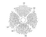
- the tower type solar power plant shown in Fig. 1 controls a solar heat receiver placed on a high tower and a reflected light called a heliostat placed on the ground around the solar heat receiver. It is possible to generate electricity by concentrating sunlight on a solar heat receiver at the top of the tower by a heliostat.
- a heliostat field 101 is provided on the ground G. On this heliostat field 101, a plurality of heliostats 102 for reflecting sunlight are arranged.
- a tower-type solar light collecting heat receiver 100 that receives solar light guided by the heliostat 102 is provided at the center of the heliostat field 101.
- the heliostat 102 is disposed on the entire 360 ° circumference of the tower-type solar light collecting heat receiver 100.
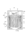
- the tower-type solar condensing heat receiver 100 includes a tower 110 erected on the ground G, a storage chamber 120 above the tower 110, and a heat receiver (solar heat receiver) 10 installed in the storage chamber 120. Has been.
- the tower 110 is provided with a plurality of reinforcing members 111.
- the reinforcing members 111 are arranged so as to intersect with the height direction (longitudinal direction) of the tower 110, and are provided at intervals (distances between adjacent reinforcing members) P in the height direction of the tower 110.
- the interval P increases as it approaches the upper portion of the tower 110 (the side on which the heat receiver 10 is installed) in a range included in an optical path in which reflected light of sunlight is incident on the heat receiver 10 by the heliostat 102.
- the arrangement structure of the reinforcing member 111 may be, for example, a truss structure from the viewpoint of securing rigidity.
- the storage chamber 120 at the top of the tower 110 has a circular planar shape.
- the storage chamber 120 has two storage chambers, an upper storage chamber 121 and a lower storage chamber 122.
- an opening 122c for taking in sunlight is provided at the bottom of the lower housing chamber 122.
- the planar shape of the opening 122c is a circle.
- the diameter of the opening 122c is determined according to the spot diameter of the sunlight.
- the diameter of the opening 122c of the present embodiment is equal to or larger than the spot diameter of the sunlight.
- the spot diameter is a diameter at a position where the diameter of the luminous flux of sunlight which is reflected by the heliostat 101 of the heliostat field 101 and enters the opening 122c is the smallest.
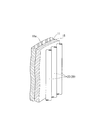
- the heat receiver 10 includes a cylindrical casing 11 and a heat receiving tube 20.
- the shape of the casing 11 is not limited to a cylindrical shape, and may be a conical shape, a polygonal column shape, a spherical shape, an elliptical shape, or a shape obtained by combining any two or more thereof.
- the heat receiver 10 is provided in the lower housing chamber 122. Specifically, the heat receiver 10 is fixed to the upper wall 122a of the lower housing chamber 122 via the hanger 12, and is suspended from the upper wall 122a in the lower housing chamber 122.
- the heat receiver 10 is arranged at a distance from the inner wall at a position away from the inner wall of the lower housing chamber 122 so as not to contact the inner wall of the lower housing chamber 122.
- a plurality of the suspension tools 12 are provided in the circumferential direction of the upper wall 122a having a circular shape and have flexibility.
- the hanger 12 penetrates the casing 11.
- the opening 11b has a circular planar shape, similar to the opening 122c described above.
- the diameter of the opening part 11b is determined according to the spot diameter of the sunlight.
- the diameter of the opening 11b of the present embodiment is equal to or larger than the spot diameter of the sunlight.
- the diameter of the opening part 11b of the casing 11 of this embodiment is equal to or smaller than the diameter of the opening part 122c of the storage chamber 120.
- the casing 11 is drawn in a cylindrical shape having the same diameter in the axial direction in order to easily explain the internal structure.
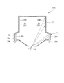
- the casing 11 of the present embodiment has an enlarged portion 11c whose diameter is expanded so that the lower portion extends outward in the radial direction, as shown in FIGS. . That is, the diameter of the lower part of the casing 11 close to the opening 11b is larger than the diameter of the upper part of the casing 11 away from the opening 11b.
- a heat receiving pipe main body 23 extending in the axial direction (vertical direction) of the casing 11 along the inner wall surface of the enlarged portion 11c is disposed inside the enlarged portion 11c.
- the gas turbine 30 that operates using the fluid (heat medium) heated by the heat receiver 10 as the working fluid and the operating energy of the gas turbine 30 are extracted as electric power into the upper housing chamber 121.
- a generator 33 is arranged.
- the gas turbine 30 sucks a fluid (for example, air) serving as a heat medium and compresses it to generate a compressed fluid, and the fluid compressed by the compressor 31 and heated by the heat receiver 10 is a working fluid.
- a turbine 32 that operates as follows. Then, the kinetic energy generated by the rotation of the turbine 32 is converted into electric energy by the generator 33 and is taken out as electric power.
- a temperature sensor that detects heat received by the heat receiver 10
- an auxiliary drive device that starts the gas turbine 30, and a working fluid before the working fluid is heated by the heat receiver 10.
- a regenerative heat exchanger for exchanging heat with the exhaust of the turbine 32, an auxiliary combustor for supplementary combustion of the working fluid and flowing into the turbine 32, a silencer for canceling vibration of the generator 33, and the like may be arranged. Good.
- the installation area of equipment can be reduced by concentrating and arranging the devices above the tower 110.
- an opening 121b for taking in fluid (atmosphere) supplied to the compressor 31 is provided on the side surface of the upper storage chamber 121.
- the opening 121b is used to discharge the exhaust from the turbine 32 to the outside as necessary.
- the heat receiving pipe 20 has a lower header pipe 21, an upper header pipe 22, and a heat receiving pipe main body 23.
- the lower header pipe 21 has an annular shape and is disposed below the casing 11. Specifically, the lower header pipe 21 is exposed to the outside of the casing 11 and is disposed in the vicinity of the lower wall 122 b in the lower housing chamber 122.
- a plurality of heat receiving pipe main bodies 23 are provided in the vertical direction between the upper header pipe 22 and the lower header pipe 21 inside the casing 11.
- the heat receiving pipe main body 23 has one end connected to the upper header pipe 22 and the other end connected to the lower header pipe 21.
- These heat receiving pipe main bodies 23 increase the temperature of the working fluid (heat medium) that flows from the lower header pipe 21 and flows through the inside thereof when irradiated with sunlight.
- the working fluid whose temperature has risen is discharged from the heat receiving pipe main body 23 to the upper header pipe 22.
- the heat receiving pipe main body 23 is provided at a predetermined interval (gap) in the circumferential direction of the upper header pipe 22 (lower header pipe 21) (see FIGS. 6 and 7).
- An end portion of the heat receiving pipe main body 23 connected to the lower header pipe 21 is exposed to the outside of the casing 11.
- Most of the heat receiving pipe main body 23 is formed in a shape (linear shape) extending straight along the axial direction (longitudinal direction) of the casing 11. A portion of the heat receiving pipe main body 23 formed in a linear shape is not subjected to bending stress due to its own weight.
- the working fluid inside the heat receiving pipe main body 23 flows in one direction from the lower header pipe 21 to the upper header pipe 22.
- the lower header tube 21 is an annular tube that is refracted into an annular shape or a polygonal shape in a plan view, and is disposed below the casing 11. Specifically, the lower header pipe 21 is exposed to the outside of the casing 11 and is disposed in the vicinity of the lower wall 122 b in the lower housing chamber 122. With the above configuration, the heat receiving pipe 20 has the upper header pipe 22 fixed to the upper wall 122a in the lower housing chamber 122 via the hanger 12 and is entirely suspended from the upper wall 122a.
- An L-shaped inlet pipe 13 is connected to the lower header pipe 21.
- a connection pipe 14 is connected between the inlet pipe 13 and the compressor 31.
- the connection pipe 14 is exposed to the outside of the casing 11 and is disposed along the inner wall of the lower housing chamber 122.
- the compressed fluid generated by the compressor 31 is supplied to the lower header pipe 21 via the connection pipe 14 and the inlet pipe 13.
- the compressed fluid (heat medium) supplied to the lower header pipe 21 flows through the plurality of heat receiving pipe main bodies 23 and the upper header pipe 22, and is heated by the heat energy of solar rays incident from the opening 11b. 23 and the upper header tube 22 are heated.
- the inner wall surface of the casing 11 is provided with a heat insulating material (heat absorbing material, heat storage material, or heat radiation shielding plate) 15 that absorbs solar heat.
- the heat insulating material 15 rises in temperature by absorbing heat, and radiates heat to the back surface of the heat receiving pipe main body 23 (the back side portion where sunlight does not directly enter).
- the back side part is heated by the thermal radiation of the heat insulating material 15, and the whole circumferential direction is heated by heating the front side part with sunlight.
- the heat insulating material 15 returns the radiant heat emitted from the heat receiving pipe main body 23 to the portion (back surface) on the back side of the heat receiving pipe main body 23, and stably heats the heat receiving pipe main body 23. Further, the heat insulating material 15 reduces the amount of heat generated from the heat receiving pipe main body 23 and the upper header pipe 22 to the outside.
- the outlet pipe 25 is connected to the upper header pipe 22 through a plurality of connection pipes 24.
- One end of each of the plurality of connection pipes 24 is connected to the upper header pipe 22, and the other end is connected to the outlet pipe 25, and is arranged in an X shape in plan view.
- the outlet pipe 25 is bent in the upper housing chamber 121 and is formed in an L shape in a cross-sectional view shown in FIG. 3B.
- the end of the outlet pipe 25 opposite to the end connected to the plurality of connection pipes 24 is connected to the turbine 32.
- the compressed fluid heated through the inside of the heat receiving pipe main body 23 and the upper header pipe 22 is supplied to the turbine 32 as a high-temperature and high-pressure working fluid via the connection pipe 24 and the outlet pipe 25.
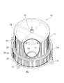
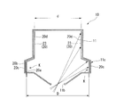
- the heat receiving pipe body 23 included in the heat receiving pipe 20 of the heat receiver 10 has a portion with a high heat flux extending in the length direction on the opening 11 b side to a position on the radially outer side of the casing 11.
- An enlarged portion 20c in which the diameter D of the pitch circle made up of the plurality of heat receiving pipe main bodies 23 is enlarged is formed. That is, the diameter D of the pitch circle of the enlarged portion 20c is larger than the diameter d of the pitch circle in the portion 20d that is not the enlarged portion 20c.
- the pitch circle is a circle that passes through the centers of the plurality of heat receiving pipe main bodies 23 and intersects the central axis of each heat receiving pipe main body 23.
- the plurality of heat receiving pipe main bodies 23 are arranged at a predetermined pitch (interval) in the circumferential direction of the casing 11, and the center is arranged on the circumference of the pitch circle.
- the plurality of heat receiving pipe main bodies 23 are arranged so as to extend in the vertical direction at intervals in the circumferential direction of the casing 11.
- the centers of the heat receiving pipe main bodies 23 are arranged on the same circumference.
- the plurality of heat receiving pipe main bodies 23 are bent toward the outer side in the radial direction of the casing 11 at a portion closer to the opening 11 b than the central portion in the vertical direction of the casing 11.
- the enlarged portion 20c is provided in the heat receiving pipe main body 23 in a region near the opening 11b of the casing 11.
- the circle passing through the centers of the plurality of heat receiving tube main bodies 23 has a diameter D in a region near the opening 11b larger than a diameter d in a region away from the opening 11b. It has been expanded.
- the heat receiving pipe main body 23 corresponds to the heat receiving pipe of the present invention.
- the heat insulating material 15 shown in FIG.4, FIG.6 and FIG.7 is abbreviate
- the enlarged portion 20c of the heat receiving pipe main body 23 is disposed at a predetermined interval along the inner surface of the enlarged portion 11c of the casing 11 described above, has a substantially trapezoidal shape in a side view, and the lower end protrudes outward from the casing 11. ing.
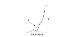
- FIG. 9 is a graph showing the effect of the enlarged portion 20c of the heat receiving pipe main body 23 included in the heat receiving pipe 20, where the vertical axis is the length dimension (distance from the opening 11b) X of the heat receiving pipe main body 23, and the horizontal axis Indicates the amount of heat input to the heat receiving pipe main body 23 (solar heat incident intensity).
- a dotted line is a result when the enlarged portion 20c is not provided in the heat receiving pipe main body 23, and a solid line is a result when the enlarged portion 20c is provided.
- FIG. 8 by providing the enlarged portion 20 c in the high temperature portion K of the heat receiving pipe main body 23 close to the opening 11 b, the solar heat incident intensity with respect to the heat receiving pipe main body 23 decreases as shown in FIG. 9.
- the diameter D of the pitch circle is enlarged at the high heat flux portion (high temperature portion K) of the heat receiving pipe main body 23 included in the heat receiving pipe 20.
- the surface area of the outer peripheral surface of the heat receiving pipe 20 in that portion increases.
- the heat receiving pipe main body 23 is disposed per unit area in the region where the heat receiving pipe main bodies 23 are widened at the high pitched portion K of the heat receiving pipe main body 23 near the opening 11b of the casing 11 and irradiated with sunlight.
- the number of 23 decreases.
- the distance between the heat receiving tube main body 23 and the opening 11b of the casing 11 where the diameter of the luminous flux of sunlight is minimized, and the energy of the sunlight directly irradiated per unit area of the surface of the heat receiving tube main body 23 Decrease.
- the heat input per unit area with respect to the heat receiving pipe main bodies 23 can be reduced (FIG. 9). reference).
- the amount of heat that is reduced in the heat receiving pipe 20 including the heat receiving pipe main body 23 is transferred from the gap between the heat receiving pipe main bodies 23 to the heat insulating material 15 (see FIG. 6 and FIG. 7) behind the heat receiving pipe main body 23.
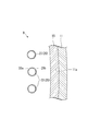
- the diameter of the enlarged portion 20e in the heat receiving pipe main body 23 included in the heat receiving pipe 20 is larger than the portion that is not the enlarged portion 20e. Is the diameter. That is, in the region where the diameter of the circle passing through the center of each heat receiving tube main body 23 is enlarged, the diameter of each heat receiving tube main body 23 is larger than the diameter of each heat receiving tube main body 23 in the other regions.
- the surface area of the outer peripheral surface of the heat receiving pipe 20 is further increased by increasing the diameter of the enlarged portion 20e of the heat receiving pipe main body 23 included in the heat receiving pipe 20, the amount of heat input per unit area is further reduced.
- the volume of the compressed fluid inside the heat receiving pipe main body 23 is increased by increasing the diameter of the heat receiving pipe main body 23.
- the heat capacity of the compressed fluid inside the heat receiving pipe main body 23 increases and the temperature hardly rises, and the temperature of the heat receiving pipe main body 23 also hardly rises. Therefore, the temperature difference between the front side portion (front surface) 20a and the back side portion (back surface) 20b of the heat receiving pipe main body 23 with respect to the incident direction of sunlight can be further reduced.
- the heat transfer promotion body 20h can be inserted into the enlarged portion 20e of the heat receiving pipe main body 23. That is, in a region where the diameter D of the circle passing through the centers of the plurality of heat receiving pipe main bodies 23 is enlarged, heat transfer enhancement having higher thermal conductivity than the heat receiving pipe main body 23 is provided inside the heat receiving pipe main body 23.
- the body 20h may be arranged. Further, the heat conductivity of the heat transfer promoting body 20h may be higher than the heat conductivity of the compressed fluid flowing inside the heat receiving pipe main body 23. According to the present embodiment, by increasing the diameter of the enlarged portion 20e of the heat receiving pipe main body 23 included in the heat receiving pipe 20, the heat transfer promoting body 20h is provided inside the heat receiving pipe main body 23 without increasing the pressure loss.
- the heat transfer coefficient inside the heat receiving pipe main body 23 can be increased.
- the length of the heat receiving pipe main body 23 can be shortened, and the heat receiver 10A can be downsized.
- the pipe diameter of the heat receiving pipe main body 23 is set to 1.3 times in the enlarged portion 20e, and the heat transfer promoting body 20h is inserted into the enlarged portion 20e so that the heat exchange amount is 1. It can be increased by 6 to 2.4 times.
- the shape of the enlarged portion 20c of the heat receiving tube 20 is substantially trapezoidal in a side view, but is not limited to such a shape.
- a tapered shape or an umbrella shape that gradually spreads outward in the radial direction of the casing 11 as it goes downward may be used.
- the pipe diameter dimension of the enlarged portion 20e of the heat receiving pipe main body 23 having a large diameter in the second embodiment can be arbitrarily set, and as described above, conditions such as the presence or absence of a heat transfer promoting body It may be determined by.
- the constituent elements in the above-described embodiment can be appropriately replaced with known constituent elements without departing from the gist of the present invention, and the above-described embodiments may be appropriately combined.
- the plurality of heat receiving tubes are arranged to extend in one direction at intervals.
- the center of each heat receiving pipe is arranged on the same circumference.
- the plurality of heat receiving pipes are bent toward the outside in the radial direction of the casing at a portion near the opening of the casing. Thereby, the diameter of the circle passing through the centers of the plurality of heat receiving tubes is larger in the area near the opening than in the area away from the opening.
Landscapes
- Engineering & Computer Science (AREA)
- Physics & Mathematics (AREA)
- Life Sciences & Earth Sciences (AREA)
- Sustainable Development (AREA)
- Sustainable Energy (AREA)
- Thermal Sciences (AREA)
- Chemical & Material Sciences (AREA)
- Combustion & Propulsion (AREA)
- Mechanical Engineering (AREA)
- General Engineering & Computer Science (AREA)
- Engine Equipment That Uses Special Cycles (AREA)
- Photovoltaic Devices (AREA)
Priority Applications (4)
| Application Number | Priority Date | Filing Date | Title |
|---|---|---|---|
| EP11739688A EP2532984A1 (en) | 2010-02-05 | 2011-01-28 | Solar heat receiver |
| US13/575,982 US20120291772A1 (en) | 2010-02-05 | 2011-01-28 | Solar heat receiver |
| AU2011211877A AU2011211877A1 (en) | 2010-02-05 | 2011-01-28 | Solar heat receiver |
| ZA2012/05741A ZA201205741B (en) | 2010-02-05 | 2012-07-30 | Solar heat receiver |
Applications Claiming Priority (2)
| Application Number | Priority Date | Filing Date | Title |
|---|---|---|---|
| JP2010-024395 | 2010-02-05 | ||
| JP2010024395A JP2011163593A (ja) | 2010-02-05 | 2010-02-05 | 太陽熱受熱器 |
Publications (1)
| Publication Number | Publication Date |
|---|---|
| WO2011096339A1 true WO2011096339A1 (ja) | 2011-08-11 |
Family
ID=44355338
Family Applications (1)
| Application Number | Title | Priority Date | Filing Date |
|---|---|---|---|
| PCT/JP2011/051790 Ceased WO2011096339A1 (ja) | 2010-02-05 | 2011-01-28 | 太陽熱受熱器 |
Country Status (6)
| Country | Link |
|---|---|
| US (1) | US20120291772A1 (enExample) |
| EP (1) | EP2532984A1 (enExample) |
| JP (1) | JP2011163593A (enExample) |
| AU (1) | AU2011211877A1 (enExample) |
| WO (1) | WO2011096339A1 (enExample) |
| ZA (1) | ZA201205741B (enExample) |
Families Citing this family (8)
| Publication number | Priority date | Publication date | Assignee | Title |
|---|---|---|---|---|
| WO2010119945A1 (ja) * | 2009-04-16 | 2010-10-21 | 三鷹光器株式会社 | 太陽光集光システム |
| MX2011002035A (es) | 2011-02-11 | 2012-08-30 | Fricaeco America S A De C V | Calentador solar de líquidos. |
| JP2013113459A (ja) * | 2011-11-25 | 2013-06-10 | Mitsubishi Heavy Ind Ltd | 太陽光受熱器及び太陽熱発電装置 |
| JP2013130372A (ja) * | 2011-12-22 | 2013-07-04 | Mitsubishi Heavy Ind Ltd | 太陽熱受熱器、その組立方法、および太陽熱受熱器を備えた太陽熱発電システム |
| US8936020B1 (en) * | 2014-03-12 | 2015-01-20 | Fricaeco America Sapi De C.V. | Solar fluids preheating system with low thermal losses |
| AU2015260468B2 (en) * | 2014-05-13 | 2019-11-21 | Niigata University | Concentrated sunlight heat receiver, reactor, and heater |
| US9534811B2 (en) | 2014-12-31 | 2017-01-03 | Fricaeco America, SAPI de C.V. | Solar fluid preheating system having a thermosiphonic aperture and concentrating and accelerating convective nanolenses |
| CN110864465B (zh) * | 2019-11-29 | 2025-03-14 | 广东技术师范大学 | 一种光聚热发电装置 |
Citations (3)
| Publication number | Priority date | Publication date | Assignee | Title |
|---|---|---|---|---|
| JP2951297B2 (ja) | 1997-10-15 | 1999-09-20 | 三鷹光器株式会社 | 太陽光集光システム |
| DE102005035080A1 (de) * | 2005-07-21 | 2007-01-25 | Deutsches Zentrum für Luft- und Raumfahrt e.V. | Solarstrahlungsempfänger und Verfahren zur Steuerung und/oder Regelung der Massenstromverteilung und/oder zum Temperaturausgleich an einem Solarstrahlungsempfänger |
| US20080011290A1 (en) * | 2006-05-11 | 2008-01-17 | Brightsource Energy, Inc. | High temperature solar receiver |
Family Cites Families (23)
| Publication number | Priority date | Publication date | Assignee | Title |
|---|---|---|---|---|
| US4099514A (en) * | 1974-01-07 | 1978-07-11 | Mario Posnansky | Method and apparatus for heating a fluid medium by means of solar energy |
| US4044753A (en) * | 1976-04-28 | 1977-08-30 | Nasa | Solar energy collection system |
| US4060071A (en) * | 1976-06-17 | 1977-11-29 | Solar Energy Dynamics Corporation | Solar collector for solar heating systems |
| US4088120A (en) * | 1976-09-02 | 1978-05-09 | Suntec Systems, Inc. | Solar concentrator-collector |
| DE2937529C2 (de) * | 1979-09-17 | 1983-05-11 | Kraftwerk Union AG, 4330 Mülheim | Sonnenkraftwerk |
| DE3004582A1 (de) * | 1980-02-08 | 1981-08-13 | M.A.N. Maschinenfabrik Augsburg-Nürnberg AG, 8000 München | Verfahren und vorrichtung zum schutz einer im bereich hochkonzentrierter strahlung befindlichen anordnung |
| US4414812A (en) * | 1981-04-30 | 1983-11-15 | R & D Associates | Hot air solar engine |
| US4449514A (en) * | 1982-06-25 | 1984-05-22 | The United States Of America As Represented By The Administrator Of The National Aeronautics And Space Administration | Solar concentrator protective system |
| DE3306800A1 (de) * | 1983-02-26 | 1984-08-30 | M.A.N. Maschinenfabrik Augsburg-Nürnberg AG, 8000 München | Waermetauscher |
| US4586487A (en) * | 1984-02-22 | 1986-05-06 | The United States Of America As Represented By The Administrator Of The National Aeronautics And Space Administration | Protective telescoping shield for solar concentrator |
| US4815443A (en) * | 1986-09-10 | 1989-03-28 | Rockwell International Corporation | Solar energy focusing assembly and storage unit |
| EP0596006B1 (en) * | 1991-07-24 | 1996-09-18 | Rheem Australia Limited | Solar collector with freeze damage protection |
| US5850831A (en) * | 1996-09-27 | 1998-12-22 | Boeing North American, Inc. | Loose-tight-loose twist, twisted-tape insert solar central receiver |
| US5862800A (en) * | 1996-09-27 | 1999-01-26 | Boeing North American, Inc. | Molten nitrate salt solar central receiver of low cycle fatigue 625 alloy |
| DE19710986C2 (de) * | 1997-03-17 | 2001-02-22 | Deutsch Zentr Luft & Raumfahrt | Volumetrischer Strahlungsempfänger und Verfahren zur Wärmegewinnung aus konzentrierter Strahlung |
| US7011086B2 (en) * | 2002-12-05 | 2006-03-14 | The Boeing Company | Bottom supported solar receiver panel apparatus and method |
| US8378280B2 (en) * | 2007-06-06 | 2013-02-19 | Areva Solar, Inc. | Integrated solar energy receiver-storage unit |
| US20100206298A1 (en) * | 2007-08-30 | 2010-08-19 | Yeda Research And Development Company Ltd. | Solar receivers and systems thereof |
| US20090241939A1 (en) * | 2008-02-22 | 2009-10-01 | Andrew Heap | Solar Receivers with Internal Reflections and Flux-Limiting Patterns of Reflectivity |
| WO2009121030A2 (en) * | 2008-03-28 | 2009-10-01 | Esolar Inc. | Solar thermal receiver for medium-and high-temperature applications |
| WO2010034071A1 (en) * | 2008-09-25 | 2010-04-01 | Solfast Pty Ltd | Solar collector |
| US20100258112A1 (en) * | 2009-04-10 | 2010-10-14 | Victory Energy Operations LLC | Generation of steam from solar energy |
| CN102741622A (zh) * | 2010-01-30 | 2012-10-17 | 黑利福卡斯有限公司 | 管状的太阳能接收器及其应用系统 |
-
2010
- 2010-02-05 JP JP2010024395A patent/JP2011163593A/ja not_active Withdrawn
-
2011
- 2011-01-28 US US13/575,982 patent/US20120291772A1/en not_active Abandoned
- 2011-01-28 AU AU2011211877A patent/AU2011211877A1/en not_active Abandoned
- 2011-01-28 EP EP11739688A patent/EP2532984A1/en not_active Withdrawn
- 2011-01-28 WO PCT/JP2011/051790 patent/WO2011096339A1/ja not_active Ceased
-
2012
- 2012-07-30 ZA ZA2012/05741A patent/ZA201205741B/en unknown
Patent Citations (3)
| Publication number | Priority date | Publication date | Assignee | Title |
|---|---|---|---|---|
| JP2951297B2 (ja) | 1997-10-15 | 1999-09-20 | 三鷹光器株式会社 | 太陽光集光システム |
| DE102005035080A1 (de) * | 2005-07-21 | 2007-01-25 | Deutsches Zentrum für Luft- und Raumfahrt e.V. | Solarstrahlungsempfänger und Verfahren zur Steuerung und/oder Regelung der Massenstromverteilung und/oder zum Temperaturausgleich an einem Solarstrahlungsempfänger |
| US20080011290A1 (en) * | 2006-05-11 | 2008-01-17 | Brightsource Energy, Inc. | High temperature solar receiver |
Also Published As
| Publication number | Publication date |
|---|---|
| US20120291772A1 (en) | 2012-11-22 |
| EP2532984A1 (en) | 2012-12-12 |
| JP2011163593A (ja) | 2011-08-25 |
| ZA201205741B (en) | 2013-04-24 |
| AU2011211877A1 (en) | 2012-08-23 |
Similar Documents
| Publication | Publication Date | Title |
|---|---|---|
| WO2011096339A1 (ja) | 太陽熱受熱器 | |
| JP5145461B2 (ja) | 太陽熱受熱器 | |
| US8378280B2 (en) | Integrated solar energy receiver-storage unit | |
| AU2008262380B2 (en) | Integrated solar energy receiver-storage unit | |
| CN102575877B (zh) | 具有改进的可制造性和效率的太阳能聚光器构型 | |
| WO2011001546A1 (ja) | 太陽熱発電システムに係るガスタービンプラント、受熱器、発電装置、太陽光集光システム | |
| CN101027524A (zh) | 太阳集热器、阳光聚集反射器、阳光聚集系统和太阳能利用系统 | |
| JP6011827B2 (ja) | 太陽光集光器およびタービンが組み合わされた装置 | |
| JP2014159892A (ja) | 太陽熱集熱装置、および、太陽熱発電システム | |
| CN209586602U (zh) | 太阳能电站 | |
| JP2011007149A (ja) | ガスタービンプラント | |
| JP5404374B2 (ja) | 太陽光受熱器及び太陽光集光受熱システム | |
| CN112484324A (zh) | 太阳能收集系统及其方法 | |
| WO2012073676A1 (ja) | 太陽熱受熱器 | |
| CN102803723A (zh) | 用于太阳能收集和自然通风冷却的塔 | |
| JP2014052153A (ja) | 太陽集熱装置 | |
| US20130213388A1 (en) | Coil solar receiver for a stirling disk and method for manufacturing same | |
| KR100995821B1 (ko) | 접시형 태양열 집광장치 | |
| JP2011032902A (ja) | 太陽光集光受熱装置 | |
| US9080790B2 (en) | Concave receiver for stirling dish and method for manufacturing the same | |
| JP2011007150A (ja) | 受熱器 | |
| JP2011163592A (ja) | 太陽熱受熱器 | |
| JP2011163595A (ja) | 太陽熱受熱器 | |
| WO2001096791A1 (en) | High temperature solar radiation heat converter | |
| CN109520155B (zh) | 一种集热模块、集热装置及塔式太阳能发电系统 |
Legal Events
| Date | Code | Title | Description |
|---|---|---|---|
| 121 | Ep: the epo has been informed by wipo that ep was designated in this application |
Ref document number: 11739688 Country of ref document: EP Kind code of ref document: A1 |
|
| WWE | Wipo information: entry into national phase |
Ref document number: 2011739688 Country of ref document: EP |
|
| WWE | Wipo information: entry into national phase |
Ref document number: 6652/CHENP/2012 Country of ref document: IN |
|
| WWE | Wipo information: entry into national phase |
Ref document number: 13575982 Country of ref document: US Ref document number: 2011211877 Country of ref document: AU |
|
| NENP | Non-entry into the national phase |
Ref country code: DE |
|
| ENP | Entry into the national phase |
Ref document number: 2011211877 Country of ref document: AU Date of ref document: 20110128 Kind code of ref document: A |