US5850831A - Loose-tight-loose twist, twisted-tape insert solar central receiver - Google Patents
Loose-tight-loose twist, twisted-tape insert solar central receiver Download PDFInfo
- Publication number
- US5850831A US5850831A US08/719,522 US71952296A US5850831A US 5850831 A US5850831 A US 5850831A US 71952296 A US71952296 A US 71952296A US 5850831 A US5850831 A US 5850831A
- Authority
- US
- United States
- Prior art keywords
- tube
- twist
- twisted
- tape
- receiver
- Prior art date
- Legal status (The legal status is an assumption and is not a legal conclusion. Google has not performed a legal analysis and makes no representation as to the accuracy of the status listed.)
- Expired - Lifetime
Links
Images


Classifications
-
- F—MECHANICAL ENGINEERING; LIGHTING; HEATING; WEAPONS; BLASTING
- F24—HEATING; RANGES; VENTILATING
- F24S—SOLAR HEAT COLLECTORS; SOLAR HEAT SYSTEMS
- F24S20/00—Solar heat collectors specially adapted for particular uses or environments
- F24S20/20—Solar heat collectors for receiving concentrated solar energy, e.g. receivers for solar power plants
-
- F—MECHANICAL ENGINEERING; LIGHTING; HEATING; WEAPONS; BLASTING
- F24—HEATING; RANGES; VENTILATING
- F24S—SOLAR HEAT COLLECTORS; SOLAR HEAT SYSTEMS
- F24S70/00—Details of absorbing elements
- F24S70/60—Details of absorbing elements characterised by the structure or construction
-
- F—MECHANICAL ENGINEERING; LIGHTING; HEATING; WEAPONS; BLASTING
- F24—HEATING; RANGES; VENTILATING
- F24S—SOLAR HEAT COLLECTORS; SOLAR HEAT SYSTEMS
- F24S80/00—Details, accessories or component parts of solar heat collectors not provided for in groups F24S10/00-F24S70/00
- F24S80/20—Working fluids specially adapted for solar heat collectors
-
- F—MECHANICAL ENGINEERING; LIGHTING; HEATING; WEAPONS; BLASTING
- F24—HEATING; RANGES; VENTILATING
- F24S—SOLAR HEAT COLLECTORS; SOLAR HEAT SYSTEMS
- F24S80/00—Details, accessories or component parts of solar heat collectors not provided for in groups F24S10/00-F24S70/00
- F24S2080/03—Arrangements for heat transfer optimization
- F24S2080/05—Flow guiding means; Inserts inside conduits
-
- Y—GENERAL TAGGING OF NEW TECHNOLOGICAL DEVELOPMENTS; GENERAL TAGGING OF CROSS-SECTIONAL TECHNOLOGIES SPANNING OVER SEVERAL SECTIONS OF THE IPC; TECHNICAL SUBJECTS COVERED BY FORMER USPC CROSS-REFERENCE ART COLLECTIONS [XRACs] AND DIGESTS
- Y02—TECHNOLOGIES OR APPLICATIONS FOR MITIGATION OR ADAPTATION AGAINST CLIMATE CHANGE
- Y02E—REDUCTION OF GREENHOUSE GAS [GHG] EMISSIONS, RELATED TO ENERGY GENERATION, TRANSMISSION OR DISTRIBUTION
- Y02E10/00—Energy generation through renewable energy sources
- Y02E10/40—Solar thermal energy, e.g. solar towers
- Y02E10/44—Heat exchange systems
Definitions
- This invention relates to using twisted-tape inserts in tubes to improve the heat transfer effectiveness of the molten nitrate salt heat transfer fluid in a solar central receiver, and more particularly for a loose-tight-loose staged twist configuration of the twisted-tape.
- receiver designs for molten salt, solar central receiver power plants are based upon a multi-smooth tube parallel flow panel, with the panel flow path arranged in a serpentine series configuration.
- This flow scheme compensates for the inherently poor heat transfer properties of molten salt, but at a cost in pressure loss because of the high velocities required to obtain acceptable heat transfer coefficients and the long flow path.
- the receiver's size is set by limiting the absorbed solar flux induced thermal strain to a value determined by the tube material's allowable fatigue strain level for the imposed number of daily sun and cloud cover cycles over the receiver's lifetime.
- the induced thermal strain is caused by the through the wall (flux, wall thickness, and thermal conductivity dependent) and across diameter temperature (flux, and internal heat transfer coefficient dependent) gradients and is proportional to the tube material's thermal expansion coefficient.
- This invention uses a loose-tight-loose twist, twisted-tape insert inside a solar central receiver's tubes to provide the smallest, most efficient and economical molten nitrate salt, solar central receiver.
- the staged twist, twisted-tape receiver is smaller and less costly than a smooth tube receiver because the twisted-tape permits a significant increase in solar flux onto the receiver at lower fluid flow pressure losses by using fewer, shorter, larger diameter tubes.
- FIG. 1 is a configuration sketch of a cylindrical, molten salt solar central receiver power plant with a surround heliostat field.
- FIG. 2 is an isometric view of a typical molten salt, solar absorption panel.
- FIG. 3 is a side view of the solar absorption panel showing a typical tube.
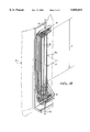
- FIG. 4 is a detail view of the panel's solar absorption tube showing the staged twist, twisted-tape insert.
- FIG. 5 is a detail view of the twisted-tape insert's end regions.
- This invention relates to improving the heat transfer effectiveness of high temperature sodium-potassium nitrate salt receivers for solar central receiver power plants.
- These receivers may be of the cavity, billboard or cylindrical, surround field type. They are used to absorb solar radiation for the generation of thermal energy for process heat or steam generation for production of electric power.
- FIG. 1 depicts a solar central cylindrical receiver 1 composed of multiple panels 30 with a surround heliostat field 2.
- the receiver 1 is mounted on a tower 3 to provide the most efficient focal point height.
- the sun 50 provides solar energy depicted as rays 51 which are reflected from heliostats 2 and are directed thereby to solar panel 10.
- FIG. 2 shows a typical molten salt solar absorption panel 30 with its absorption tubes 4 which can be of seamless, welded or welded and drawn construction; and of any ASME Boiler and Pressure Vessel Code approved construction material which is compatible with molten sodium-potassium nitrate salt and has acceptable thermal fatigue properties.
- the panel's tubes 4 are butt welded to headers 5.
- the molten salt flow 6 enters or exits the panel through its headers 5 which distributes/collects the salt flow to/from the tubes 4.
- the solar absorption area is the tube's absorption length 7 by panel width 8. This area receives the sun's 50 rays 51 from the heliostat field 2 to provide thermal energy to the flowing molten salt.
- the receiver 1 is composed of multiple panels 30 arranged in two circuits, each with eight panels, having a serpentine flow path and forming a polyhedral, cylindrical surface.
- FIG. 3 shows a side view of the solar absorption panel with its key components.
- the tube 4 is composed of a straight section 9 and two end bends 10. These are welded together with butt welds 11 which are located out of the solar absorption length 7.
- the tube 4 is supported on the strong back 12 through tube supports 13 which provide for free axial expansion.
- the hot absorption tubes are insulated on their back-side with ceramic fiber blanket 14 to minimize heat losses.
- FIG. 4 shows a detail of the solar absorption tube 4 with the staged twist, twisted-tape insert 15 located within the straight section 9.
- the twisted-tape 15 is composed of two loose twist sections 16, one at each end, and a central tight twist section 17. As shown in FIG. 4, the loose twist sections 16 are located within the low flux regions 18 to minimize the molten salt's fluid flow pressure loss.
- the loose twist pitch/diameter ratio and its extent are determined by evaluating the tube's thermal strain over the entrance and exit regions for all panels. The maximum loose twist pitch/diameter ratio that provides a significant region of reduced pressure loss while meeting the tube's allowable thermal fatigue limit is selected to minimize operating costs.
- the tight twist section 17 is located in the high flux region 19 to provide the cooling necessary to hold the tube's thermal strains within the tube material's fatigue allowables.
- the receiver solar flux distribution along the panel's length is set in a low-high-low pattern 18-19-18 so that the receiver can be as small as practicable while providing low flux regions at each end to avoid over-heating uncooled structures.
- the twisted-tape insert 15 should be constructed from a material that matches the tube material's coefficient of thermal expansion and molten salt's corrosion resistance.
- a material that matches the tube material's coefficient of thermal expansion and molten salt's corrosion resistance For example, Inconel alloy 625 LCF® for both tube and twisted-tape.
- the twisted-tape insert 15 is located and constrained within the tube 4 by the slight bow caused by welding the attachment to the tube at each tube support attachment point 20. During operation an additional outward bow (towards the sun's rays) due to the flux induced temperature difference across the tube's diameter constrains and holds the twisted-tape insert against fluid flow and seismic induced forces. As a back-up to these restraints the insert ends are formed 21 and located 22 to provide a physical stop against the tube butt weld drop-through 23 as shown in FIG. 5. The insert is located a sufficient distance 22 from the butt weld 11 at each end to avoid interference with the weld process and to eliminate buckling the insert 15 due to relative thermal growth between the twisted-tape insert 15 and tube 9.
- the solar central receiver's solar absorption area is significantly reduced by the use of the staged twist, twisted-tape insert as demonstrated in Table 1.
- Table 1 clearly shows the substantial size and performance improvements obtained by the use of a staged twist, twisted-tape insert in lieu of a smooth tube for a receiver constructed from Inconel alloy 625 LCF®.
- a peak absorbed heat flux greater than the 1.60 MW/M 2 for the twisted-tape insert tubed panel shown in Table 1 is achievable by decreasing the tube diameter to increase the salt's heat transfer coefficient (which effectively decreases the across the tube diameter temperature difference, hence tube thermal strain) or reducing the tube wall thickness below 0.049 inches to decrease the through wall thermal gradient, hence tube thermal strain. Because the selected wall thickness of 0.049 inches is set by the requirement to obtain reliable butt and tube wall attachment welds this approach cannot be used, while reducing the tube diameter results in increased pumping power costs due to larger pressure losses and increased receiver fabrication costs due to the larger number of smaller diameter tubes required.
Abstract
Description
              TABLE 1
______________________________________
Loose-Tight-Loose Twist, Twisted-Tape Insert Yields Size and
Performance Improvements for a Surround Field, Molten Salt,
Solar Central, Inconel Alloy 625
LCF ® Cylindrical Receiver Rated at 468 MW(T)
                             Twisted-Tape
Configuration     Smooth Tube
                             Insert
______________________________________
Receiver Area (M.sup.2)
                  648        574
Pressure Loss (PSID)
                  228        204
Efficiency (%)    90.2       90.5
Highest Power Panel
Average absorbed heat flux
                  1.15       1.29
(MW/M.sup.2)
Peak absorbed heat flux (MW/M.sup.2)
                  1.42       1.60
Average incident flux (MW/M.sup.2)
                  .80        .90
Solar Absorption Panel
Length (ft.)      47.1       44.74
Width (ft.)       9.25       8.63
Tube, OD (in.)    1.50       2.25
wall thickness (in.)
                  0.049      0.049
Number of tubes   74         46
Tape twist: pitch/diameter
                  N/A        12-3.2-12
Twist length (ft.)
                  N/A        8.15-28.44-8.15
Heat transfer coefficient
                  1380       1210-1570-1210
 ##STR1##
Number of flow circuits
                  2
Number of panels/flow circuit
                  8
Salt temperature,
inlet (°F.)
                  550
outlet (°F.)
                  1050
______________________________________
Claims (3)
Priority Applications (1)
| Application Number | Priority Date | Filing Date | Title |
|---|---|---|---|
| US08/719,522 US5850831A (en) | 1996-09-27 | 1996-09-27 | Loose-tight-loose twist, twisted-tape insert solar central receiver |
Applications Claiming Priority (1)
| Application Number | Priority Date | Filing Date | Title |
|---|---|---|---|
| US08/719,522 US5850831A (en) | 1996-09-27 | 1996-09-27 | Loose-tight-loose twist, twisted-tape insert solar central receiver |
Publications (1)
| Publication Number | Publication Date |
|---|---|
| US5850831A true US5850831A (en) | 1998-12-22 |
Family
ID=24890395
Family Applications (1)
| Application Number | Title | Priority Date | Filing Date |
|---|---|---|---|
| US08/719,522 Expired - Lifetime US5850831A (en) | 1996-09-27 | 1996-09-27 | Loose-tight-loose twist, twisted-tape insert solar central receiver |
Country Status (1)
| Country | Link |
|---|---|
| US (1) | US5850831A (en) |
Cited By (30)
| Publication number | Priority date | Publication date | Assignee | Title |
|---|---|---|---|---|
| US6708687B2 (en) * | 2001-06-12 | 2004-03-23 | James B. Blackmon, Jr. | Thermally controlled solar reflector facet with heat recovery |
| US6736134B2 (en) * | 2001-09-05 | 2004-05-18 | The Boeing Company | Thin wall header for use in molten salt solar absorption panels |
| US20040112374A1 (en) * | 2002-12-13 | 2004-06-17 | Litwin Robert Z. | Solar central receiver with inboard headers |
| US20050126560A1 (en) * | 2003-12-10 | 2005-06-16 | The Boeing Company | Solar collector and method |
| US20050126170A1 (en) * | 2003-12-10 | 2005-06-16 | The Boeing Company | Solar power system and method for power generation |
| US6957536B2 (en) | 2003-06-03 | 2005-10-25 | The Boeing Company | Systems and methods for generating electrical power from solar energy |
| ES2263394A1 (en) * | 2006-02-01 | 2006-12-01 | Sener, Ingenieria Y Sistemas, S.A. | Thin wall header with a variable cross-section for solar absorption panels |
| WO2010093547A2 (en) * | 2009-02-12 | 2010-08-19 | Babcock Power Services Inc. | Arrangement of tubing in solar boiler panels |
| US20100242949A1 (en) * | 2009-03-30 | 2010-09-30 | Mitsubishi Heavy Industries, Ltd. | Sunlight collecting heat receiver |
| US20110079217A1 (en) * | 2009-02-12 | 2011-04-07 | Babcock Power Services, Inc. | Piping, header, and tubing arrangements for solar boilers |
| US20110114085A1 (en) * | 2009-02-12 | 2011-05-19 | Babcock Power Services, Inc. | Heat transfer passes for solar boilers |
| US20110232629A1 (en) * | 2010-03-23 | 2011-09-29 | Johnny Mandel | Thermal shield for solar receiver |
| US20120031094A1 (en) * | 2009-02-13 | 2012-02-09 | Nem B.V. | Solar receiver having back positioned header |
| US20120291772A1 (en) * | 2010-02-05 | 2012-11-22 | Mitsubisi Heavy Industries, Ltd | Solar heat receiver |
| US8356591B2 (en) | 2009-02-12 | 2013-01-22 | Babcock Power Services, Inc. | Corner structure for walls of panels in solar boilers |
| EP2503260A3 (en) * | 2011-03-23 | 2013-01-23 | Kabushiki Kaisha Toshiba | Solar heat collecting apparatus and solar power generation system |
| DE102011052998A1 (en) * | 2011-08-25 | 2013-02-28 | Hitachi Power Europe Gmbh | By means of a heat transfer medium heatable heat exchanger tube of a solar thermal system and heat transfer method |
| US8397710B2 (en) | 2009-02-12 | 2013-03-19 | Babcock Power Services Inc. | Solar receiver panels |
| US8430092B2 (en) | 2009-02-12 | 2013-04-30 | Babcock Power Services, Inc. | Panel support system for solar boilers |
| US8490618B2 (en) | 2007-07-26 | 2013-07-23 | Brightsource Industries (Israel) Ltd. | Solar receiver |
| US8517008B2 (en) | 2009-02-12 | 2013-08-27 | Babcock Power Services, Inc. | Modular solar receiver panels and solar boilers with modular receiver panels |
| WO2013128048A1 (en) | 2012-03-01 | 2013-09-06 | Abengoa Solar New Technologies, S.A. | Solar receiver panels |
| WO2013008131A3 (en) * | 2011-07-14 | 2013-09-06 | Foster Wheeler North America Corp. | Solar heat receiver system |
| US8573196B2 (en) | 2010-08-05 | 2013-11-05 | Babcock Power Services, Inc. | Startup/shutdown systems and methods for a solar thermal power generating facility |
| US8893714B2 (en) | 2009-02-12 | 2014-11-25 | Babcock Power Services, Inc. | Expansion joints for panels in solar boilers |
| US9038624B2 (en) | 2011-06-08 | 2015-05-26 | Babcock Power Services, Inc. | Solar boiler tube panel supports |
| US9163857B2 (en) | 2009-02-12 | 2015-10-20 | Babcock Power Services, Inc. | Spray stations for temperature control in solar boilers |
| US9726155B2 (en) | 2010-09-16 | 2017-08-08 | Wilson Solarpower Corporation | Concentrated solar power generation using solar receivers |
| CN107690205A (en) * | 2017-09-30 | 2018-02-13 | 江苏众众热能科技有限公司 | A kind of electric heater for solar-thermal generating system header |
| US10876521B2 (en) | 2012-03-21 | 2020-12-29 | 247Solar Inc. | Multi-thermal storage unit systems, fluid flow control devices, and low pressure solar receivers for solar power systems, and related components and uses thereof |
Citations (5)
| Publication number | Priority date | Publication date | Assignee | Title |
|---|---|---|---|---|
| US4044753A (en) * | 1976-04-28 | 1977-08-30 | Nasa | Solar energy collection system |
| US4384550A (en) * | 1980-12-19 | 1983-05-24 | Rockwell International Corporation | Thermal receiver |
| US4485803A (en) * | 1982-10-14 | 1984-12-04 | The Babcock & Wilcox Company | Solar receiver with interspersed panels |
| US4641705A (en) * | 1983-08-09 | 1987-02-10 | Gorman Jeremy W | Modification for heat exchangers incorporating a helically shaped blade and pin shaped support member |
| US4993485A (en) * | 1989-09-18 | 1991-02-19 | Gorman Jeremy W | Easily disassembled heat exchanger of high efficiency |
-
1996
- 1996-09-27 US US08/719,522 patent/US5850831A/en not_active Expired - Lifetime
Patent Citations (5)
| Publication number | Priority date | Publication date | Assignee | Title |
|---|---|---|---|---|
| US4044753A (en) * | 1976-04-28 | 1977-08-30 | Nasa | Solar energy collection system |
| US4384550A (en) * | 1980-12-19 | 1983-05-24 | Rockwell International Corporation | Thermal receiver |
| US4485803A (en) * | 1982-10-14 | 1984-12-04 | The Babcock & Wilcox Company | Solar receiver with interspersed panels |
| US4641705A (en) * | 1983-08-09 | 1987-02-10 | Gorman Jeremy W | Modification for heat exchangers incorporating a helically shaped blade and pin shaped support member |
| US4993485A (en) * | 1989-09-18 | 1991-02-19 | Gorman Jeremy W | Easily disassembled heat exchanger of high efficiency |
Non-Patent Citations (1)
| Title |
|---|
| Friction and Heat Transfer Characteristics in Turbulent Swirl Flow Subjected to Large Transverse Temperature Gradients, Journal of Heat Transfer, Feb. 1968, p. 87, R. Thorsen, F. Landis. * |
Cited By (55)
| Publication number | Priority date | Publication date | Assignee | Title |
|---|---|---|---|---|
| US20040139960A1 (en) * | 2001-06-12 | 2004-07-22 | Blackmon James B. | Thermally controlled solar reflector facet with heat recovery |
| US20040139961A1 (en) * | 2001-06-12 | 2004-07-22 | Blackmon James B. | Thermally controlled solar reflector facet with heat recovery |
| US20040140051A1 (en) * | 2001-06-12 | 2004-07-22 | Blackmon James B. | Thermally controlled solar reflector facet with heat recovery |
| US6708687B2 (en) * | 2001-06-12 | 2004-03-23 | James B. Blackmon, Jr. | Thermally controlled solar reflector facet with heat recovery |
| US7669593B2 (en) | 2001-06-12 | 2010-03-02 | Pratt & Whitney Rocketdyne, Inc. | Thermally controlled solar reflector facet with heat recovery |
| US6911110B2 (en) | 2001-06-12 | 2005-06-28 | The Boeing Company | Thermally controlled solar reflector facet with heat recovery |
| US6736134B2 (en) * | 2001-09-05 | 2004-05-18 | The Boeing Company | Thin wall header for use in molten salt solar absorption panels |
| US6931851B2 (en) | 2002-12-13 | 2005-08-23 | The Boeing Company | Solar central receiver with inboard headers |
| US20040112374A1 (en) * | 2002-12-13 | 2004-06-17 | Litwin Robert Z. | Solar central receiver with inboard headers |
| US6957536B2 (en) | 2003-06-03 | 2005-10-25 | The Boeing Company | Systems and methods for generating electrical power from solar energy |
| US7055519B2 (en) | 2003-12-10 | 2006-06-06 | United Technologies Corporation | Solar collector and method |
| US7296410B2 (en) | 2003-12-10 | 2007-11-20 | United Technologies Corporation | Solar power system and method for power generation |
| US20050126170A1 (en) * | 2003-12-10 | 2005-06-16 | The Boeing Company | Solar power system and method for power generation |
| US20050126560A1 (en) * | 2003-12-10 | 2005-06-16 | The Boeing Company | Solar collector and method |
| CN101379350B (en) * | 2006-02-01 | 2011-11-16 | Sener工程系统私人控股公司 | Thin wall header with a variable cross-section for solar absorption panels |
| ES2263394A1 (en) * | 2006-02-01 | 2006-12-01 | Sener, Ingenieria Y Sistemas, S.A. | Thin wall header with a variable cross-section for solar absorption panels |
| WO2007088031A1 (en) * | 2006-02-01 | 2007-08-09 | Sener, Ingenieria Y Sistemas, S.A. | Thin wall header with a variable cross-section for solar absorption panels |
| US20090250051A1 (en) * | 2006-02-01 | 2009-10-08 | Sener, Ingenieria Y Sistemas, S.A. | Thin wall header with a variable cross-section for solar absorption panels |
| US8186341B2 (en) | 2006-02-01 | 2012-05-29 | Sener, Ingenieria Y Sistemas, S.A. | Thin wall header with a variable cross-section for solar absorption panels |
| US8490618B2 (en) | 2007-07-26 | 2013-07-23 | Brightsource Industries (Israel) Ltd. | Solar receiver |
| US8316843B2 (en) | 2009-02-12 | 2012-11-27 | Babcock Power Services Inc. | Arrangement of tubing in solar boiler panels |
| US20110114085A1 (en) * | 2009-02-12 | 2011-05-19 | Babcock Power Services, Inc. | Heat transfer passes for solar boilers |
| US9163857B2 (en) | 2009-02-12 | 2015-10-20 | Babcock Power Services, Inc. | Spray stations for temperature control in solar boilers |
| US20110079217A1 (en) * | 2009-02-12 | 2011-04-07 | Babcock Power Services, Inc. | Piping, header, and tubing arrangements for solar boilers |
| US8733340B2 (en) | 2009-02-12 | 2014-05-27 | Babcock Power Services, Inc. | Arrangement of tubing in solar boiler panels |
| WO2010093547A3 (en) * | 2009-02-12 | 2010-11-25 | Babcock Power Services Inc. | Arrangement of tubing in solar boiler panels |
| US9134043B2 (en) * | 2009-02-12 | 2015-09-15 | Babcock Power Services Inc. | Heat transfer passes for solar boilers |
| AU2010213976B2 (en) * | 2009-02-12 | 2016-05-12 | Babcock Power Services Inc. | Arrangement of tubing in solar boiler panels |
| US8356591B2 (en) | 2009-02-12 | 2013-01-22 | Babcock Power Services, Inc. | Corner structure for walls of panels in solar boilers |
| ES2422504R1 (en) * | 2009-02-12 | 2013-09-23 | Babcock Power Services Inc | Arrangement of tubes in solar boiler panels |
| US8517008B2 (en) | 2009-02-12 | 2013-08-27 | Babcock Power Services, Inc. | Modular solar receiver panels and solar boilers with modular receiver panels |
| US8893714B2 (en) | 2009-02-12 | 2014-11-25 | Babcock Power Services, Inc. | Expansion joints for panels in solar boilers |
| US8397710B2 (en) | 2009-02-12 | 2013-03-19 | Babcock Power Services Inc. | Solar receiver panels |
| US8430092B2 (en) | 2009-02-12 | 2013-04-30 | Babcock Power Services, Inc. | Panel support system for solar boilers |
| WO2010093547A2 (en) * | 2009-02-12 | 2010-08-19 | Babcock Power Services Inc. | Arrangement of tubing in solar boiler panels |
| US8984882B2 (en) * | 2009-02-13 | 2015-03-24 | Nem Energy B.V. | Solar receiver having back positioned header |
| US20120031094A1 (en) * | 2009-02-13 | 2012-02-09 | Nem B.V. | Solar receiver having back positioned header |
| US20100242949A1 (en) * | 2009-03-30 | 2010-09-30 | Mitsubishi Heavy Industries, Ltd. | Sunlight collecting heat receiver |
| US8360053B2 (en) * | 2009-03-30 | 2013-01-29 | Mitsubishi Heavy Industries, Ltd. | Sunlight collecting heat receiver |
| US20120291772A1 (en) * | 2010-02-05 | 2012-11-22 | Mitsubisi Heavy Industries, Ltd | Solar heat receiver |
| US9644865B2 (en) | 2010-03-23 | 2017-05-09 | Solarreserve Technology, Llc | Thermal shield for solar receiver |
| US20110232629A1 (en) * | 2010-03-23 | 2011-09-29 | Johnny Mandel | Thermal shield for solar receiver |
| US8573196B2 (en) | 2010-08-05 | 2013-11-05 | Babcock Power Services, Inc. | Startup/shutdown systems and methods for a solar thermal power generating facility |
| US9347685B2 (en) | 2010-08-05 | 2016-05-24 | Babcock Power Services Inc. | Startup systems and methods for solar boilers |
| US9726155B2 (en) | 2010-09-16 | 2017-08-08 | Wilson Solarpower Corporation | Concentrated solar power generation using solar receivers |
| US10280903B2 (en) | 2010-09-16 | 2019-05-07 | Wilson 247Solar, Inc. | Concentrated solar power generation using solar receivers |
| US11242843B2 (en) | 2010-09-16 | 2022-02-08 | 247Solar Inc. | Concentrated solar power generation using solar receivers |
| EP2503260A3 (en) * | 2011-03-23 | 2013-01-23 | Kabushiki Kaisha Toshiba | Solar heat collecting apparatus and solar power generation system |
| US8820076B2 (en) | 2011-03-23 | 2014-09-02 | Kabushiki Kaisha Toshiba | Solar heat collecting apparatus and solar power generation system |
| US9038624B2 (en) | 2011-06-08 | 2015-05-26 | Babcock Power Services, Inc. | Solar boiler tube panel supports |
| WO2013008131A3 (en) * | 2011-07-14 | 2013-09-06 | Foster Wheeler North America Corp. | Solar heat receiver system |
| DE102011052998A1 (en) * | 2011-08-25 | 2013-02-28 | Hitachi Power Europe Gmbh | By means of a heat transfer medium heatable heat exchanger tube of a solar thermal system and heat transfer method |
| WO2013128048A1 (en) | 2012-03-01 | 2013-09-06 | Abengoa Solar New Technologies, S.A. | Solar receiver panels |
| US10876521B2 (en) | 2012-03-21 | 2020-12-29 | 247Solar Inc. | Multi-thermal storage unit systems, fluid flow control devices, and low pressure solar receivers for solar power systems, and related components and uses thereof |
| CN107690205A (en) * | 2017-09-30 | 2018-02-13 | 江苏众众热能科技有限公司 | A kind of electric heater for solar-thermal generating system header |
Similar Documents
| Publication | Publication Date | Title |
|---|---|---|
| US5850831A (en) | Loose-tight-loose twist, twisted-tape insert solar central receiver | |
| US4394859A (en) | Central solar energy receiver | |
| KR101688934B1 (en) | Combined gas-water tube hybrid heat exchanger | |
| US8517008B2 (en) | Modular solar receiver panels and solar boilers with modular receiver panels | |
| US4384550A (en) | Thermal receiver | |
| Wang et al. | Thermal-fluid-mechanical analysis of tubular solar receiver panels using supercritical CO2 as heat transfer fluid under non-uniform solar flux distribution | |
| JP5951396B2 (en) | Heat collector for solar boiler and tower solar boiler equipped with the same | |
| CN104428606A (en) | Solar receiver panels | |
| CA2409341C (en) | Radiant energy absorbers | |
| US9127857B2 (en) | High efficiency solar receiver | |
| RU2674850C2 (en) | Tube for heat exchanger with at least partially variable cross-section and heat exchanger equipped therewith | |
| CN110044080B (en) | Tower type solar thermal power generation system based on cavity column type heat collector | |
| JPH0573961B2 (en) | ||
| CN104676568A (en) | Steam generator and steam generation system based on line focusing solar heat collection | |
| CN208967835U (en) | Water-cooling wall in low nitrogen water-tube boiler | |
| Ho et al. | Collector efficiency of double-pass sheet-and-tube solar water heaters with internal fins attached | |
| US4713213A (en) | Nuclear reactor plant housed in a steel pressure vessel with a gas cooled small high temperature reactor | |
| EP3894759A1 (en) | Heat transfer device | |
| CN204534504U (en) | Based on steam generator and the steam generating system of line-focusing solar thermal-arrest | |
| JPS61190286A (en) | Heat exchanger | |
| CN210119022U (en) | Tower type solar thermal power generation system based on cavity column type heat collector | |
| RU2383814C1 (en) | Steam generator | |
| Wright et al. | The development of an 85-kW (thermal) steam Rankine solar receiver | |
| AU776857B2 (en) | Radiant energy absorbers | |
| JP5890067B2 (en) | Absorbing structure for trough concentrator |
Legal Events
| Date | Code | Title | Description |
|---|---|---|---|
| AS | Assignment |
Owner name: ROCKWELL INTERNATIONAL CORPORATION, CALIFORNIA Free format text: ASSIGNMENT OF ASSIGNORS INTEREST;ASSIGNOR:MARKO, MYROSLAW;REEL/FRAME:008227/0720 Effective date: 19960927 |
|
| AS | Assignment |
Owner name: BOEING NORTH AMERICAN, INC., CALIFORNIA Free format text: MERGER;ASSIGNOR:ROCKWELL INTERNATIONAL CORPORATION;REEL/FRAME:008765/0315 Effective date: 19961206 |
|
| STCF | Information on status: patent grant |
Free format text: PATENTED CASE |
|
| FEPP | Fee payment procedure |
Free format text: PAYOR NUMBER ASSIGNED (ORIGINAL EVENT CODE: ASPN); ENTITY STATUS OF PATENT OWNER: LARGE ENTITY |
|
| FPAY | Fee payment |
Year of fee payment: 4 |
|
| REMI | Maintenance fee reminder mailed | ||
| AS | Assignment |
Owner name: BOEING COMPANY, THE, ILLINOIS Free format text: MERGER;ASSIGNOR:BOEING NORTH AMERICAN, INC.;REEL/FRAME:016570/0454 Effective date: 19991230 |
|
| AS | Assignment |
Owner name: UNITED TECHNOLOGIES CORPORATION,CONNECTICUT Free format text: ASSIGNMENT OF ASSIGNORS INTEREST;ASSIGNOR:BOEING COMPANY AND BOEING MANAGEMENT COMPANY, THE;REEL/FRAME:017681/0537 Effective date: 20050802 Owner name: UNITED TECHNOLOGIES CORPORATION, CONNECTICUT Free format text: ASSIGNMENT OF ASSIGNORS INTEREST;ASSIGNOR:BOEING COMPANY AND BOEING MANAGEMENT COMPANY, THE;REEL/FRAME:017681/0537 Effective date: 20050802 |
|
| AS | Assignment |
Owner name: UNITED TECHNOLOGIES CORPORATION,CONNECTICUT Free format text: ASSIGNMENT OF ASSIGNORS INTEREST;ASSIGNOR:BOEING C OMPANY AND BOEING MANAGEMENT COMPANY, THE;REEL/FRAME:017882/0126 Effective date: 20050802 Owner name: UNITED TECHNOLOGIES CORPORATION, CONNECTICUT Free format text: ASSIGNMENT OF ASSIGNORS INTEREST;ASSIGNOR:BOEING C OMPANY AND BOEING MANAGEMENT COMPANY, THE;REEL/FRAME:017882/0126 Effective date: 20050802 |
|
| REMI | Maintenance fee reminder mailed | ||
| FPAY | Fee payment |
Year of fee payment: 8 |
|
| SULP | Surcharge for late payment |
Year of fee payment: 7 |
|
| FPAY | Fee payment |
Year of fee payment: 12 |
|
| AS | Assignment |
Owner name: RUBY ACQUISITION ENTERPRISES CO., CALIFORNIA Free format text: CORRECTIVE ASSIGNMENT TO CORRECT THE ASSIGNEE'S NAME ON ORIGINAL COVER SHEET PREVIOUSLY RECORDED ON REEL 017882 FRAME 0126. ASSIGNOR(S) HEREBY CONFIRMS THE ASSIGNEE WAS INCORRECTLY RECORDED AS "UNITED TECHNOLOGIES CORPORATION". ASSIGNEE SHOULD BE "RUBY ACQUISITION ENTERPRISES CO.";ASSIGNOR:THE BOEING COMPANY AND BOEING MANAGEMENT COMPANY;REEL/FRAME:030592/0954 Effective date: 20050802 Owner name: PRATT & WHITNEY ROCKETDYNE, INC., CALIFORNIA Free format text: CHANGE OF NAME;ASSIGNOR:RUBY ACQUISITION ENTERPRISES CO.;REEL/FRAME:030593/0055 Effective date: 20050802 |
|
| AS | Assignment |
Owner name: WELLS FARGO BANK, NATIONAL ASSOCIATION, NORTH CARO Free format text: SECURITY AGREEMENT;ASSIGNOR:PRATT & WHITNEY ROCKETDYNE, INC.;REEL/FRAME:030628/0408 Effective date: 20130614 |
|
| AS | Assignment |
Owner name: U.S. BANK NATIONAL ASSOCIATION, CALIFORNIA Free format text: SECURITY AGREEMENT;ASSIGNOR:PRATT & WHITNEY ROCKETDYNE, INC.;REEL/FRAME:030656/0615 Effective date: 20130614 |
|
| AS | Assignment |
Owner name: AEROJET ROCKETDYNE OF DE, INC., CALIFORNIA Free format text: CHANGE OF NAME;ASSIGNOR:PRATT & WHITNEY ROCKETDYNE, INC.;REEL/FRAME:032845/0909 Effective date: 20130617 |
|
| AS | Assignment |
Owner name: SOLARRESERVE TECHNOLOGY, LLC, CALIFORNIA Free format text: ASSIGNMENT OF ASSIGNORS INTEREST;ASSIGNOR:AEROJET ROCKETDYNE OF DE;REEL/FRAME:034530/0978 Effective date: 20141009 |
|
| AS | Assignment |
Owner name: AEROJET ROCKETDYNE OF DE, INC., CALIFORNIA Free format text: RELEASE BY SECURED PARTY;ASSIGNOR:U.S. BANK NATIONAL ASSOCIATION;REEL/FRAME:036666/0103 Effective date: 20141021 |
|
| AS | Assignment |
Owner name: AEROJET ROCKETDYNE OF DE, INC. (F/K/A PRATT & WHIT Free format text: RELEASE BY SECURED PARTY;ASSIGNOR:U.S. BANK NATIONAL ASSOCIATION;REEL/FRAME:039597/0890 Effective date: 20160715 |