WO2011096285A1 - 口腔ケア装置 - Google Patents
口腔ケア装置 Download PDFInfo
- Publication number
- WO2011096285A1 WO2011096285A1 PCT/JP2011/051095 JP2011051095W WO2011096285A1 WO 2011096285 A1 WO2011096285 A1 WO 2011096285A1 JP 2011051095 W JP2011051095 W JP 2011051095W WO 2011096285 A1 WO2011096285 A1 WO 2011096285A1
- Authority
- WO
- WIPO (PCT)
- Prior art keywords
- frequency
- brush
- brushing
- unit
- detected
- Prior art date
Links
Images


Classifications
-
- A—HUMAN NECESSITIES
- A61—MEDICAL OR VETERINARY SCIENCE; HYGIENE
- A61C—DENTISTRY; APPARATUS OR METHODS FOR ORAL OR DENTAL HYGIENE
- A61C17/00—Devices for cleaning, polishing, rinsing or drying teeth, teeth cavities or prostheses; Saliva removers; Dental appliances for receiving spittle
- A61C17/16—Power-driven cleaning or polishing devices
- A61C17/22—Power-driven cleaning or polishing devices with brushes, cushions, cups, or the like
- A61C17/32—Power-driven cleaning or polishing devices with brushes, cushions, cups, or the like reciprocating or oscillating
- A61C17/34—Power-driven cleaning or polishing devices with brushes, cushions, cups, or the like reciprocating or oscillating driven by electric motor
- A61C17/3409—Power-driven cleaning or polishing devices with brushes, cushions, cups, or the like reciprocating or oscillating driven by electric motor characterized by the movement of the brush body
- A61C17/3481—Vibrating brush body, e.g. by using eccentric weights
-
- A—HUMAN NECESSITIES
- A61—MEDICAL OR VETERINARY SCIENCE; HYGIENE
- A61C—DENTISTRY; APPARATUS OR METHODS FOR ORAL OR DENTAL HYGIENE
- A61C17/00—Devices for cleaning, polishing, rinsing or drying teeth, teeth cavities or prostheses; Saliva removers; Dental appliances for receiving spittle
- A61C17/16—Power-driven cleaning or polishing devices
- A61C17/22—Power-driven cleaning or polishing devices with brushes, cushions, cups, or the like
- A61C17/221—Control arrangements therefor
Definitions
- This invention relates to an oral care device, and relates to an oral care device having a function of detecting a vibration frequency by an acceleration sensor.
- An example of an oral care device is an electric toothbrush.
- brush pressure In brushing using an electric toothbrush, in order to remove plaque effectively, control of the load acting on the brush when the brush is in contact with the teeth (hereinafter referred to as brush pressure) Is known to be important.
- the brush pressure on the teeth of the brush can generally be detected based on the current consumption of the motor (Patent Document 1 (Japanese Patent Laid-Open No. 2005-152217)).
- detection can be performed using a strain gauge (Japanese Patent Laid-Open No. 10-108734).
- the motor heats up as the operating time elapses, and the current consumption changes accordingly even if the motor operates at a constant frequency, so the detection accuracy is not sufficient. It was.
- an object of the present invention is to provide an oral care device that can obtain a reference value (standard value) for estimating a load acting on an oral care member with a simple configuration.
- the frequency detection unit detects the frequency based on the waveform of the output signal of the acceleration sensor.
- the oral care device detects a member pressure indicating a load acting on the care member based on the frequency detected by the frequency detection unit.
- the drive unit is a motor
- the frequency detection unit detects the member pressure based on the difference between the frequency due to rotation of the motor when there is no load and the frequency detected by the frequency detection unit.
- the drive unit is a motor
- the oral care device further includes a consumption current detection unit that detects a consumption current of the motor.
- the frequency detection unit further detects the frequency based on the current consumption detected by the current consumption detection unit.
- the oral care device is supplied to the drive unit based on a power source that supplies power to each unit of the device, a power detection unit that detects power output from the power source, and a value of power detected by the power detection unit. And a power compensation unit that compensates for the power to be generated.
- the power compensation unit changes the duty ratio of the pulse signal given to the drive unit for driving based on the value of the power detected by the power detection unit.
- the oral care device notifies the detected member pressure.
- the oral care device displays the detected frequency.
- the frequency that is a reference value (standard value) for estimating the member pressure of the oral care member can be obtained with a simple configuration using an acceleration sensor.
- an electric toothbrush having a brush implanted on the surface of a housing will be described as an example of an oral care device.
- the configuration of the embodiment is used for oral care (tooth cleaning, brushing, gum massage, etc.). It can be applied to any device that can.
- a material used for oral care it can be applied to a device using an oral care member in which a resin component such as sponge, rubber, elastomer or the like and a brush and these resin components are combined instead of a toothbrush.
- the brush pressure described above corresponds to “member pressure” indicating a load acting on the care member.
- FIG. 1 is a block diagram of a display system including an electric toothbrush
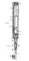
- FIG. 2 is a cross-sectional view illustrating an internal configuration example of the electric toothbrush
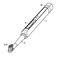
- FIG. 3 is a perspective view illustrating an external appearance example of a display system including the electric toothbrush. It is.
- the electric toothbrush 1 includes a main body 2 (hereinafter also simply referred to as “main body 2”) in which a motor 10 that is a driving source is incorporated, and a vibration member 5 that vibrates when the motor 10 is driven. Therefore, the vibration member 5 is regarded as an electric toothbrush main body, and the rotation speed of the motor 10 corresponds to the vibration frequency of the electric toothbrush main body.
- the main body 2 has a generally cylindrical shape, and also serves as a handle portion for the user to hold with his / her hand when brushing his / her teeth.
- the electric toothbrush 1 of the present embodiment includes a charger 100 for charging the electric toothbrush 1 on which the main body 2 is mounted, and a display 110 for outputting a brushing result.
- the main body 2 is provided with a switch S for turning on / off the power source and switching an operation mode of the motor 10 described later. Further, inside the main body 2, there are a motor 10 (for example, a direct current motor) that is a driving source, a driving circuit 12, a rechargeable battery 13 that is a power source with a rated output of 2.4V for supplying power to each part, and a coil for charging. 14 etc. are provided. When charging the rechargeable battery 13, the main body 2 is simply placed on the charger 100 and can be charged in a non-contact manner by electromagnetic induction.
- a motor 10 for example, a direct current motor
- a driving circuit 12 for example, a driving circuit 12
- a rechargeable battery 13 that is a power source with a rated output of 2.4V for supplying power to each part
- the drive circuit 12 stores a CPU (Central Processing Unit) 120 that executes various operations and controls, a program, various setting values, and a memory 121 that stores tables TB1 to TB5 (described later), a timer 122, data A transmission unit 123 and the like are included.
- the data transmission unit 123 performs wireless communication with the data reception unit 112 of the display device 110.
- the display device 110 includes a display 111 for outputting data such as a brushing result received by the data receiving unit 112.
- the main body 2 is integrally provided with a display unit 16 for displaying the brushing result.
- a display unit 16 for displaying the brushing result.
- FIG. 3 the appearance of the electric toothbrush 1 attached to the charger 100 is shown in association with the display device 110.
- a multi-axis (here, x, y, z three-axis) acceleration sensor 15 is provided in the main body 2, in order to detect the posture of the electric toothbrush 1, for example.
- the acceleration sensor 15 is installed so that the x-axis is parallel to the brush surface, the y-axis is coincident with the longitudinal direction of the main body 2, and the z-axis is perpendicular to the brush surface. Is done. That is, when the main body 2 is placed on the charger 100, the gravitational acceleration vector is parallel to the y-axis, and when the brush surface is directed upward, the gravitational acceleration vector is parallel to the z-axis.
- each axis of the acceleration sensor 15 is input to the CPU 120 and used to detect the three-dimensional posture of the brush.
- a piezoresistive type, a capacitance type, or a heat detection type MEMS (Micro Electro Mechanical Systems) sensor can be preferably used. This is because the MEMS sensor is very small and can be easily incorporated into the body 2.
- the form of the acceleration sensor 15 is not limited to this, and an electrodynamic sensor, a strain gauge sensor, a piezoelectric sensor, or the like may be used.
- a band pass filter (low pass filter) for removing dynamic acceleration components and noise may be provided. Further, noise may be reduced by smoothing the output waveform of the acceleration sensor.
- the vibrating member 5 includes a stem portion 20 fixed to the main body 2 side and a brush component 21 attached to the stem portion 20.
- a brush 210 is planted at the tip of the brush component 21. Since the brush part 21 is a consumable part, it is configured to be detachable from the stem portion 20 so that it can be replaced with a new one.
- the brush component 21 of the vibration member 5 includes a brush portion where the brush 210 is disposed and a handle portion located on the main body 2 side.
- the configuration in which the brush part 21 including a relatively long handle portion is replaced is shown.
- the brush component alone or the brush component including the brush portion and the short handle portion may be replaced. Good. That is, all or part of the handle may be included in the main body.
- the stem portion 20 is made of a resin material.
- the stem portion 20 is attached to the main body 2 via an elastic member 202 made of an elastomer.
- the stem portion 20 is a cylindrical member whose tip (brush side end) is closed, and has a bearing 203 at the tip inside the tube.
- the tip of the eccentric shaft 30 connected to the rotating shaft 11 of the motor 10 is inserted into the bearing 203 of the stem portion 20.
- the eccentric shaft 30 has a weight 300 in the vicinity of the bearing 203, and the center of gravity of the eccentric shaft 30 is deviated from the center of rotation. A minute clearance is provided between the tip of the eccentric shaft 30 and the bearing 203.
- the electric toothbrush 1 further includes an electrode-type contact detection unit 50 for detecting the presence or absence of contact or approach.
- the contact detection unit 50 detects contact or proximity to a living body, that is, the buccal mucosa and the tongue, during brushing.
- the contact detection unit 50 includes an electrode unit 52 and a detection unit 54 for detecting impedance from the electrode unit 52.
- the detection unit 54 may be mounted in the drive circuit 12.
- the detection unit 54 in the drive circuit 12 can detect the impedance by detecting the current flowing through the electric circuit of the electrode unit 52.
- Contact or proximity to the buccal mucosa and tongue is detected by the impedance value.
- the CPU 120 supplies a drive signal (for example, PWM ((Pulse Width Modulation) signal)) according to the operation mode to the motor 10 to rotate the rotating shaft 11 of the motor 10.
- the eccentric shaft 30 also rotates with the rotation of the rotating shaft 11.
- the eccentric shaft 30 moves so as to turn around the center of rotation because the center of gravity is shifted, so that the tip of the eccentric shaft 30 repeatedly collides with the inner wall of the bearing 203, and the stem portion 20 and
- the motor 10 vibrates (moves) at high speed with the mounted brush component 21. That is, the motor 10 serves as a drive unit that vibrates (moves) the brush, and the eccentric shaft 30 vibrates the output (rotation) of the motor 10. It plays the role of a motion transmission mechanism (motion conversion mechanism) that converts the vibration into the member 5.
- a motion transmission mechanism motion conversion mechanism
- the user can perform brushing by holding the main body 2 by hand and applying a brush 210 that vibrates at high speed to the teeth.
- the CPU 120 monitors the continuous operation time using the timer 122, and automatically stops the vibration of the brush when a predetermined time (for example, 2 minutes) elapses.
- the eccentric shaft 30 that is a motion transmission mechanism is included in the vibration member 5, and in particular, the weight 300 is disposed in the vicinity of the brush 210. Therefore, the portion of the brush 210 can be vibrated efficiently.
- the vibration member 5 stem part 20
- the vibration of the vibration member 5 is difficult to be transmitted to the main body 2. Therefore, the vibration of the main body 2 and the hand when brushing teeth can be reduced, and the usability can be improved.
- the electric toothbrush 1 accurately estimates the brushing region based on the brush posture (posture information) detected by the acceleration sensor 15 and the detection result of the contact detection unit 50, thereby Each brushing evaluation is realized.
- Various evaluation items are conceivable, but here, three items of brushing time, brush angle, and brush pressure are evaluated.
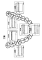
- the upper and lower dentitions are represented by “maxillary anterior cheek side”, “maxillary anterior tongue side”, “maxillary left cheek side”, “maxillary left tongue side”, “maxillary right cheek side”, “maxillary right tongue” 12 parts of “side”, “mandibular anterior cheek side”, “mandibular anterior tongue side”, “mandibular left cheek side”, “mandibular left lingual side”, “mandibular right cheek side”, “mandibular right lingual side” Divide into
- the division of the dentition is not limited to this, and may be a broader division or a finer division.
- upper, lower, left and right meshing surfaces may be considered.
- FIG. 4 is a flowchart of the main routine
- FIGS. 5 to 7 and FIG. 21 are flowcharts showing details of each process of the main routine. Note that the processing described below is processing executed by the CPU 120 according to a program stored in the memory 121 unless otherwise specified.
- step S (hereinafter simply referred to as S) 5).
- the posture (tilt) of the brush is detected based on the output of the acceleration sensor 15 (S10).
- the CPU 120 estimates a brushing part based on at least the posture detected in S10 (S20).
- the CPU 120 performs brushing time measurement (S30), brush angle estimation (S40), and brush pressure detection (S50). These pieces of information are recorded in the memory 121 for each part (see FIG. 10) and output (S55).
- the processes of S10 to S55 are repeatedly executed at regular time intervals.
- the CPU 120 determines, for each part, based on the brushing information (brushing time, brush angle, brush pressure) recorded in the memory 121.
- the brushing result is evaluated, and the evaluation result is output to the display 110 (S60).
- the brushing information in the memory 121 is cleared each time the electric toothbrush 1 is turned on.
- FIG. 5 is a flowchart of the posture detection process (S10).
- CPU 120 obtains the respective outputs Ax, Ay, Az of x, y, z from the acceleration sensor 15 (S100).
- Ax represents an acceleration component in the x direction
- Ay represents an acceleration component in the y direction
- Az represents an acceleration component in the z direction.
- A (Ax, Ay, Az) is called an attitude vector.
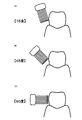
- the CPU 120 determines whether the brushing part is the upper jaw or the lower jaw based on the output Az of the acceleration sensor in the z direction (S700).
- the determination is focused on the fact that the brush surface is upward rather than a little, and when brushing the lower jaw, the brush surface is not less than downward.
- Az> 0 is established, the lower jaw (S801) is determined, and when Az ⁇ 0, the upper jaw (S701) is determined.
- the CPU 120 determines whether or not the brushing part is an anterior tooth based on the output Ay of the acceleration sensor in the y direction (S702).
- the toothbrush main body 2 is relatively horizontal when brushing the front teeth, but the determination is focused on the fact that the toothbrush main body 2 must be inclined because of interference with the lips when brushing the molars.
- Ay ⁇ threshold a it is determined that the upper jaw is an anterior tooth (S703).
- the CPU 120 determines whether the brushing part is the buccal side or the tongue side based on the output Ax of the acceleration sensor in the x direction (S704). This determination is focused on the fact that the direction of the brush is reversed between the cheek side and the tongue side. When Ax> 0 is established, it is determined as “upper maxillary cheek side” (S705), and when Ax ⁇ 0 is established, it is determined as “upper maxillary tongue side” (S706).
- the CPU 120 determines the direction of the brush based on the output Ax of the acceleration sensor in the x direction (S707).
- the brushing part is determined as “upper right cheek side or upper left tongue side” (S708), and when Ax ⁇ 0 is satisfied, it is determined as “upper left cheek side or upper maxillary right tongue side”. (S712).
- the CPU 120 narrows down the parts based on the brushing part determined in the previous process (process one clock before) (S709, S713).
- the previous brushing part is any one of “upper front cheek side, upper right cheek side, upper maxillary tongue side, lower maxillary front cheek side, lower jaw right cheek side, lower jaw right tongue side”
- the current brushing site is estimated to be “maxillary right cheek side” (S710), and the previous brushing site is “maxillary anterior tongue side, maxillary left cheek side, maxillary left lingual side, mandibular anterior tongue side, mandibular left cheek. If it is one of the left side and the lower left lingual side, it is estimated that the current brushing site is the upper left lingual side (S711).
- the previous brushing site is any one of “maxillary anterior cheek side, maxillary left cheek side, maxillary left lingual side, mandibular anterior cheek side, mandibular left cheek side, mandibular left lingual side” It is estimated that the part is “upper left cheek side” (S714), and the previous brushing part is “upper maxillary tongue side, maxillary right cheek side, maxillary right tongue side, mandibular anterior tongue side, mandibular right cheek side, mandibular right If it is one of “lingual side”, it is estimated that the current brushing site is “maxillary right lingual side” (S715). The reason for this estimation is that there is a high probability that the brushing part is moved so that the amount of movement and the direction change of the brush are minimized.
- the CPU 120 determines whether or not it is an anterior tooth based on the output Ay of the acceleration sensor 15 in the y direction (S802).
- the toothbrush main body 2 is relatively horizontal when brushing the front teeth, but the determination is focused on the fact that the toothbrush main body 2 must be inclined because of interference with the lips when brushing the molars. If Ay ⁇ threshold value b holds, the brushing part is determined to be the lower anterior tooth (S803).
- the CPU 120 determines whether the brushing part is the buccal side or the tongue side based on the output Ax of the acceleration sensor in the x direction (S804). This determination is focused on the fact that the direction of the brush is reversed between the cheek side and the tongue side.
- Ax ⁇ 0 is established, it is determined as “mandibular anterior cheek side” (S805), and when Ax ⁇ 0 is established, it is determined as “mandibular anterior tongue side” (S806).
- the CPU 120 determines the direction of the brush based on the output Ax of the acceleration sensor in the x direction (S807).
- Ax> 0 it is determined as “mandibular right cheek side or mandibular left tongue side” (S808), and when Ax ⁇ 0 is established, it is determined as “mandibular left cheek side or mandibular right tongue side” ( S812).
- the previous brushing part is any one of “mandibular anterior cheek side, mandibular right cheek side, mandibular right tongue side, mandibular anterior cheek side, maxillary right cheek side, maxillary right tongue side” Is estimated to be “mandibular right buccal side” (S810), and the previous brushing site is “mandibular anterior tongue side, mandibular left cheek side, mandibular left tongue side, maxillary anterior tongue side, maxillary left buccal side, maxillary left tongue If it is “side”, it is estimated that the current brushing part is “the lower left lingual side” (S811).
- the previous brushing site is any of “mandibular anterior cheek side, mandibular left cheek side, mandibular left lingual side, maxillary anterior cheek side, maxillary left cheek side, maxillary left lingual side” It is estimated that the region is “mandibular left cheek side” (S814), and the previous brushing region is “mandibular anterior tongue side, mandibular right cheek side, mandibular right tongue side, maxillary anterior tongue side, maxillary right cheek side, maxillary right If it is either “lingual side”, the current brushing site is estimated to be “mandibular right lingual side” (S815).
- the current brushing sites are “maxillary anterior cheek side” (S705), “maxillary anterior tongue side” (S706), “maxillary right cheek side” (S710), and “maxillary left lingual side” (S711).
- the above determination algorithm is merely an example, and any determination algorithm may be used as long as the brushing part can be specified from the outputs Ax, Ay, and Az of the acceleration sensor 15.
- secondary variables obtained by appropriately combining Ax, Ay, and Az may be used for determination.
- the secondary variable for example, Ay / Az, Ax ⁇ Ax + Ay ⁇ Ay, Az ⁇ Ax, and the like can be arbitrarily set.
- the brushing part may be determined.
- the x-axis angle with respect to the gravitational acceleration direction is defined as a roll angle ⁇
- the y-axis angle with respect to the gravitational acceleration direction is defined as a pitch angle ⁇
- the z-axis angle with respect to the gravitational acceleration direction is defined as a yaw angle ⁇ .
- the threshold used for determination can be determined from the results of clinical experiments or the like.
- FIG. 10 shows an example of brushing information recorded in the memory 121.
- FIG. 10 is an example of a state where the lower jaw left cheek side is brushed. Before the lower jaw left cheek side, the upper jaw cheek side is brushed for 7.5 seconds, and the upper jaw left cheek side is brushed for 12.2 seconds. Note that “-” indicates that no data is recorded, that is, the portion has not been brushed yet.
- the CPU 120 counts up the brushing time of the brushing part (in the example of FIG. 10, lower left cheek side) estimated in S20. For example, if the processing of S10 to S50 in FIG. 4 is executed once every 0.1 second, the brushing time on the lower jaw left cheek side is counted up by +0.1 to 2.1 seconds.
- the cumulative value of the brushing time is recorded. That is, for example, when the brushing part moves to the upper left cheek side again, the stored brushing time is not reset, but the brushing time is added to the stored value of 12.2 seconds.
- the CPU 120 estimates the brush angle based on the posture (output of the acceleration sensor 15) detected in S10, and determines the brush angle of the current brushing part (the lower jaw left cheek side in the example of FIG. 9). Update the value. At this time, it is preferable that the CPU 120 calculates and records the average value of the brush angle from the stored brush angle value and the current estimated value.
- the brush angle is the contact angle of the brush with respect to the tooth axis (axis along the tooth head and root).
- the brush angle is preferably in the range of 35 to 55 degrees.
- the brush angle can be estimated from, for example, the acceleration component Az in the z direction. As shown in FIG. 12, when the brush angle is about 90 degrees, Az is almost 0, and as the brush angle becomes smaller, the value of Az increases. Thus, the value of Az changes significantly according to the brush angle. Because it does. Since the acceleration component Ax in the x direction also changes according to the brush angle, the brush angle is estimated from Ax instead of Az, or the brush angle is calculated from both Ax and Az (the direction of the combined vector of Ax and Az). It is also preferable to estimate.
- the brush angle may be calculated as a continuous amount or may be a rough estimate such as “less than 35 degrees”, “35 degrees to 55 degrees”, or “55 degrees or more”.
- the CPU 120 estimates (detects) the brush pressure based on the output of the acceleration sensor 15, and updates the brush pressure value of the current brushing site (in the example of FIG. 10, the lower jaw left cheek side). At this time, the CPU 120 preferably calculates and records the average value of the brush pressure from the value of the brush pressure stored in the memory 121 and the current detected value.
- the brush pressure of the electric toothbrush 1 may be lower than that of an ordinary toothbrush, it is said that most people who have started using the electric toothbrush 1 tend to exceed the brush pressure.
- the optimum value of the brush pressure is about 100 to 200 g.
- the CPU 120 evaluates the brushing result for each part based on the brushing information recorded in the memory 121 in S55 or S60 of FIG. 4, and outputs the evaluation result to the display 110 (display 111).
- FIG. 13 is an output example of the evaluation result of the brushing time.
- the CPU 120 reads the brushing time of each part from the memory 121 and evaluates, for example, “insufficient” for less than 7 seconds, “good” for 7 to 15 seconds, and “excess” for more than 15 seconds.
- the evaluation result is transmitted to the display device 110.
- a tooth row is drawn on the display 111 of the display device 110, and the corresponding part in the tooth row is a color corresponding to the evaluation result (“insufficient” is white, “good” is yellow, “excess” is red, etc.) Lights on. By confirming such a display, the user can intuitively grasp which part of the dentition is insufficient (or excessive).
- FIG. 14 is an example of output of brush angle evaluation results.
- the evaluation is made in three stages, “less than 35 degrees”, “35 degrees to 55 degrees”, and “55 degrees or more”, and each part in the dentition is lit in a color according to the evaluation result.
- the plaque removing power is inferior to the optimal brush angle, so that the desired brushing effect may not be obtained or the brushing may take time. If the evaluation of the brush angle for each part is output as shown in FIG. 14, the user can be made aware of brushing by the correct brush angle.
- FIG. 15 is an output example of the evaluation result of the brush pressure. For example, if it is less than 100 g, it is evaluated as “insufficient”, 100 g to 200 g as “good”, and more than 200 g as “excessive”, and each part in the dentition is lit in a color corresponding to the evaluation result.
- the brush pressure is not appropriate, problems such as a decrease in plaque removal power, a decrease in brush life, and an increase in burden on the gums may occur. However, it is difficult for the user to understand how much force is applied to achieve the optimum brush pressure.
- the evaluation of the brush pressure for each part is output as shown in FIG. 15, the user can be taught the appropriate brush pressure and can be made aware of the brushing by the correct brush pressure.
- FIG. 16 is an output example of the evaluation result of the brushing index.
- the brushing index is an index for comprehensively evaluating a plurality of evaluation items (brushing time, brush angle, brush pressure), and represents the achievement level of brushing.
- the formula for calculating the brushing index may be defined in any way.
- the brushing time and the brush pressure are each set to a maximum of 35 points
- the brush angle is set to a maximum of 30 points
- the total of these values maximum of 100 points
- the brushing index is evaluated in three stages of “excellent”, “good”, and “impossible”.
- 80 or more brushing indexes are evaluated as “excellent”, 60 to 80 points as “good”, and less than 60 points as “impossible”.
- the initial state before brushing is shown on the left side of FIG. 16, and the evaluation after brushing is shown in association with each part of the dentition of the jaw shown schematically on the right side.
- the posture of the electric toothbrush 1 and the brushing part can be identified with high accuracy by using the output of the acceleration sensor 15. Therefore, it is possible to evaluate the brushing result with fine divisions (parts), and to provide a user with a useful and reliable evaluation guideline. Moreover, since the acceleration sensor 15 is small, there is an advantage that it can be easily incorporated into the body of the electric toothbrush 1.
- evaluation results in FIGS. 13 to 16 may be displayed on the display 111 simultaneously or sequentially. In the latter case, display switching may be performed automatically or by a user's button operation.
- the result is automatically displayed when the electric toothbrush 1 is turned off.
- toothbrushing is performed at a location different from the installation location of the display device 110, for example, when the user presses a button provided on the display device 110 or the toothbrush body 2, the display is performed from the toothbrush body 2.
- the brushing information and evaluation results stored in the memory 121 may be printed.
- a printer (not shown) may be mounted on the charger or display, or print data may be transmitted from the toothbrush body, charger or display to an external printer.
- a function of transferring brushing information and evaluation result data to an external device (not shown) (such as a personal computer, a mobile phone, or a PDA (Portable Digital Assistant)) by wireless communication or wired communication is also preferable.
- a memory card slot (not shown) may be provided in the toothbrush main body, charger, display, etc. so that brushing information and evaluation result data can be recorded in an external memory card.
- optimum values target values
- a brush angle of 35 ° to 55 ° is preferable in order to effectively scrape food residue and plaque from the periodontal pockets and teeth between the brush tips.
- a larger angle for example, 55 to 90 degrees
- the brush angle is preferably about 0 degree with respect to the mating surface of the molar.
- the optimal brushing time, brush angle, and brush pressure can be determined not from the viewpoint of the brushing effect but from the viewpoint of avoiding damage to tissues such as gums. Thus, if an optimum value is set for each part and evaluation is performed, a more useful and reliable evaluation guideline can be provided.
- the brush pressure is detected (estimated) using any one of Ax, Ay, and Az that are voltage signals output from the acceleration sensor 15.
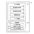
- FIG. 17 shows a functional configuration for brush pressure estimation according to the embodiment.
- Each unit in FIG. 17 is realized by a combination of a program and a circuit whose execution is controlled by the CPU 120. These programs are stored in advance in a predetermined area of the memory 121.
- the CPU 120 reads out the program from the memory 121 and executes the instruction code of the read program, thereby realizing the functions of the respective units.
- the CPU 120 includes a brush pressure estimation unit 1201 for estimating the brush pressure and a PWM control unit 120A for driving the motor 10 according to the PWM control.
- the brush pressure estimation unit 1201 consumes the dynamic acceleration component processing unit 153, the static acceleration component processing unit 155, and the motor 10 that process the dynamic acceleration component and static acceleration component signals of the electric toothbrush 1 among the output signals of the acceleration sensor 15.
- the output signal of the current detection unit 104 indicating current (supply current) is input, the consumption current detection unit 156 that detects the consumption current of the motor 10 based on the input signal, the table TB1 of the memory 121 are searched, and the search result is output.
- a table search unit 157 is included.
- the PWM control unit 120A includes a pulse signal generation unit 16A that generates a pulse signal for controlling driving of the motor 10.
- the pulse signal generation unit 16A generates a pulse signal using a pulse signal generation circuit (not shown).
- the pulse signal generation unit 16A includes an operation mode input unit 17A that inputs an operation mode instructed by the user operating the switch S, and a duty ratio determination unit 18A that determines the duty ratio of the pulse signal based on the input operation mode.
- Have The pulse signal generation unit 16A generates and outputs a pulse signal having the determined duty ratio.
- the output pulse signal is given to the motor 10 as a drive signal.
- FIG. 18 schematically shows the acceleration sensor 15 and its peripheral circuits.
- the filter unit 103 is connected to the output stage of the acceleration sensor 15.
- the filter unit 103 receives an output signal from the acceleration sensor 15 and passes only a signal in a predetermined frequency band.
- a BPF (Band Pass Filter) 151 and an HPF (High Pass Filter) connected in parallel to the output stage of the BPF 151.
- a dynamic acceleration component processing unit 153 is connected to the output stage of the HPF 152, and a static acceleration component processing unit 155 is connected to the output stage of the LPF 154.
- the HPF 152 passes only a signal having a frequency equal to or higher than a predetermined cutoff frequency (for example, 90 Hz) from the input signal from the BPF 151 and outputs the signal.
- the LPF 154 passes and outputs only a signal having a frequency equal to or lower than a predetermined cutoff frequency (for example, several Hz) among the input signals from the BPF 151.
- the dynamic acceleration component processing unit 153 receives and processes the signal 10D output from the HPF 152, thereby detecting the frequency of the electric toothbrush 1 body accompanying the rotation operation of the motor 10.
- the signal 10D output from the HPF 152 corresponds to a signal having a frequency (for example, a frequency band of 100 Hz to 300 Hz) caused by the rotation (vibration) of the motor 10.
- the static acceleration component processing unit 155 receives and processes the signal 10S output from the LPF 154.
- the input signal 10S corresponds to a signal having a frequency (for example, a frequency band of several Hz) resulting from an operation of changing the posture of the brush, such as a user who is brushing teeth twists the electric toothbrush 1. Therefore, the signal 10S corresponds to a signal of a posture information component of the electric toothbrush 1 main body.
- FIG. 19A shows an example of the waveform of the output signal of the BPF 151 shown in FIG. 18 as time elapses.
- a vibration component caused by a rotational operation of the motor 10 which is a high frequency component of 100 Hz to 300 Hz is added to a signal 10S which is a low frequency component of several Hz or less (indicated by a thick solid line in the figure).
- the signal 10D (indicated by a thin solid line in the figure) is superimposed, but the signals 10D and 10S can be separated and output by passing through the filter unit 103 described above.
- FIG. 19B the signal 10D in a certain time zone shown in FIG. 19A is extracted and enlarged.
- the dynamic acceleration component processing unit 153 receives the signal 10D, and detects the slope of the waveform for each predetermined period T (hereinafter referred to as sampling period T) with respect to the waveform of the input signal 10D. This inclination can be detected by differentiating the waveform.
- the dynamic acceleration component processing unit 153 detects the slope (positive slope or negative slope) of the waveform indicated by the signal 10D for each sampling period T, and the length of the period in which the positive slope continues or the negative slope is detected. The length of the continuous period and the timing of switching from a positive slope to a negative slope (or from a negative slope to a positive slope) are detected. Based on the detection result, the frequency of the signal 10D, that is, the frequency of the electric toothbrush 1 is detected. The detected frequency is output to the table search unit 157.
- the frequency detection method is not limited to the method shown in FIG.
- extreme values maximum value and minimum value
- the frequency of the signal 10D that is, the frequency of vibration
- the frequency of the signal 10D is determined based on the number of maximum values and minimum values detected in a predetermined time period. May be detected.
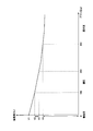
- the graph of FIG. 20 shows the correlation between the frequency and the load (here, brush pressure).
- the graph in FIG. 20 indicates data based on the experiment results of the inventors.
- the vertical axis represents the frequency (Hz)
- the horizontal axis represents the load (gram: g) applied to the motor 10.
- the motor 10 rotates at the fastest speed when there is no load (no load) in a state where the same drive signal is given from the PWM control unit 120A, and the rotation speed decreases as the load increases.
- the frequency of the electric toothbrush 1 due to the rotation of the motor 10 indicates the maximum frequency V1
- the brush 210 is pressed against the teeth so that the entire brush 210 is loaded.
- the brush pressure increases.
- the load applied to the motor 10 increases, the rotational speed of the motor 10 decreases, and the frequency decreases.
- the frequency of the motor 10 is detected in the range of the appropriate frequency V2 to V3.
- an excessive load of 500 g is applied to the entire brush 210, for example, when the brush 210 is strongly pressed against the teeth, an excessive load is applied to the motor 10, and the frequency is the frequency at the time of excessive pressure. It changes in the range of V4-0.
- the brush pressure can be uniquely determined (detected) based on the frequency of the signal 10D, that is, based on the frequency.
- the frequency data indicated by the characteristics of the graph of FIG. 20 and the corresponding brush pressure data are associated and stored in advance in the table TB1.
- the table search unit 157 searches the table TB1 based on the vibration frequency output from the dynamic acceleration component processing unit 153, and reads the brush pressure corresponding to the vibration frequency from the table TB1 based on the search result.
- the brush pressure estimation unit 1201 can detect (estimate) the brush pressure.
- FIG. 21 shows a schematic flowchart of brush pressure detection (estimation) processing according to the present embodiment.
- the brush pressure estimation unit 1201 inputs the output signal of the acceleration sensor 15 via the filter unit 103 (step SS (hereinafter simply referred to as SS) 3).
- the dynamic acceleration component processing unit 153 detects the vibration frequency according to the above-described procedure (detection of vibration frequency) (SS5).
- the table search unit 157 searches the table according to the above-described procedure (detection of brush pressure based on frequency) (SS7), and detects the brush pressure ( SS9). Thereby, the brush pressure is determined (estimated).
- the brush pressure estimation unit 1201 estimates the brush pressure based only on the vibration frequency of the motor 10 in the above-described procedure, but may detect the vibration frequency based on the current supplied to the motor 10.
- FIG. 22 shows a graph of load characteristics of the motor 10 according to the present embodiment.
- the vertical axis of the graph of FIG. 22 shows the rotation speed (rpm) of the motor 10 and the supply current to the motor 10 (that is, the consumption current of the motor 10) (unit: A).
- the torque (load) applied to the motor 10 is shown on the horizontal axis.
- This torque corresponds to the brush pressure described above.
- a straight line SA in FIG. 22 represents an ideal characteristic that the current supplied to the motor 10 increases as the torque (load) increases.
- the straight line RA represents the characteristic that the rotational speed of the motor 10 decreases as the torque (load) increases.
- the supply current data pointed to by the straight line SA and the corresponding torque data are detected in advance by experiments and are associated with each other and stored in the table TB2.
- the supply current to the motor 10 is detected by the current consumption detector 156 using the current detector 104.
- the current detection unit 104 corresponds to a resistance element connected to the input stage of the drive signal of the motor 10.
- the consumption current detection unit 156 detects the current supplied to the motor 10 by measuring the voltage applied to the resistance element and dividing the measured voltage by the resistance value of the resistance element. Note that detection using a current sensor may be used instead of detection using a resistance value.
- the supply current to the motor 10 increases as the torque increases from 0, but the motor 10 generates heat as the supply current increases. That is, when the torque indicates the predetermined value TH (> 0), if the current of the value SA1 is supplied to the motor 10, if the torque exceeds the predetermined value TH, the supply current (> SA1) to the motor 10 ), The current consumed for heat generation increases, and the straight line SA does not show the ideal correlation as shown in FIG.
- the brush 10 is based on the supply current of the motor 10 according to the relationship between the supply current of the motor 10 and the torque indicated by the straight line SA. It is possible to detect the pressure.
- the table TB1 is searched based on the frequency as described above, not the current consumption. Detect brush pressure.
- the current value SA1 is detected in advance by experiment and stored in the memory 121.
- the brush pressure estimation unit 1201 compares the current value detected by the current consumption detection unit 156 with the current value SA1 read from the memory 121, and controls the table search unit 157 based on the comparison result.
- the table search unit 157 performs the table TB2 based on the current consumption value of the motor 10 detected by the current consumption detection unit 156. Control to search.
- the table search unit 157 reads the corresponding torque (brush pressure) from the table TB2 based on the search result.
- the table search unit 157 is controlled to search the table TB1 based on the frequency as described above.
- the table search unit 157 reads the corresponding brush pressure from the table TB1 based on the search result.
- the brush pressure estimation unit 1201 can accurately estimate the brush pressure based on one or both of the current consumption and the vibration frequency of the motor 10.
- FIG. 23 schematically shows the change with time of the output voltage of the rechargeable battery 13.
- the output voltage indicates the remaining battery level of the rechargeable battery 13.
- the graph of FIG. 23 shows the characteristics obtained by experiments.
- the vertical axis represents the output voltage (unit: V) of the battery, and the horizontal axis represents the elapsed time t.
- a nickel metal hydride battery is generally used as the rechargeable battery 13.
- the rated output of the rechargeable battery 13 is assumed to be 2.4 V, for example.
- the output voltage can be maintained at the rated output (2.4V), but the output voltage decreases as the usage time elapses.
- the output voltage is maintained at the rated voltage (2.4V) until the end of the battery life (time t1).
- time t1 When the time t1 is reached, the output voltage becomes zero.
- typical batteries do not exhibit such ideal characteristics. That is, as shown by the broken line in FIG.
- the rechargeable battery 13 cannot gradually maintain the rated voltage (2.4 V), and the elapsed time from the start of use becomes time t2 ( ⁇ t1). When the output voltage becomes 2.0 V, it rapidly decreases thereafter. When the output voltage of the rechargeable battery 13 is 2.0 V or less, the electric toothbrush 1 cannot exhibit a sufficient operating capability and cannot obtain a sufficient frequency.
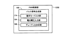
- the CPU 120 includes a PWM control unit 120B in FIG. 24 instead of the PWM control unit 120A in FIG.
- PWM control unit 120B includes a pulse signal generation unit 16B that generates a pulse signal for controlling driving of motor 10.
- the pulse signal generator 16B generates a pulse signal using a pulse signal generation circuit (not shown).
- the pulse signal generation unit 16B receives an operation mode input unit 17A for inputting an operation mode instructed by the user by operating the switch S, and a detection signal of the voltage monitor 102.
- the pulse signal generator 16B Based on the input detection signal, the pulse signal generator 16B The battery voltage input unit 19A that detects the output voltage and the duty ratio determination unit 18B that determines the duty ratio of the pulse signal based on the operation mode and the output voltage of the rechargeable battery 13 are included. The pulse signal generation unit 16B generates and outputs a pulse signal having the determined duty ratio. The pulse signal is given to the motor 10 as a drive signal.
- the duty ratio refers to the length of a period in which the voltage level with respect to the length of one cycle is ON when the length of one cycle of the pulse signal is 100%.
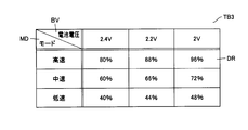
- FIG. 26 shows an example of a table TB3 referred to by the duty ratio determination unit 18B in order to change the duty ratio.
- the table TB3 stores the duty ratio DR for making the electric power supplied to the motor 10 constant corresponding to each set of the operation mode type MD of the electric toothbrush 1 and the output voltage value BV of the rechargeable battery 13. Is done.
- the data of the table TB3 is acquired in advance by experiments.
- 2.4 V, 2.2 V, and 2 V are stored as the output voltage value BV
- the operation mode type MD is “high-speed” mode that vibrates at high speed, and “medium-speed” mode that vibrates at a lower speed than that.
- three types of “low speed” modes that vibrate at a lower speed are stored. Note that the number of types of output voltage values BV and the number of types of operation modes MD to be stored are not limited thereto.
- the operation mode input unit 17A inputs the type of operation mode specified by the user operating the switch S, and the battery voltage input unit 19A detects the output voltage of the rechargeable battery 13.
- the duty ratio determination unit 18B searches the table TB3 in FIG. 26 based on the set of the input operation mode type and the detected output voltage. Based on the search result, the duty ratio DR corresponding to the set is read from the table TB3.
- the pulse signal generation unit 16B generates and outputs a pulse signal having the read duty ratio DR. The output pulse signal is given to the motor 10 as a drive signal.
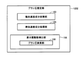
- FIG. 27 shows a functional configuration of a brush pressure estimation unit 1202 having a brush pressure search function.
- a brush pressure estimation unit 1202 may be used instead of the brush pressure estimation unit 1201 of FIG.
- the brush pressure estimation unit 1202 includes a dynamic acceleration component processing unit 153, a static acceleration component processing unit 155, and a differential frequency detection unit 158 including a brush pressure search unit 159.
- the rest of the configuration excluding the differential frequency detection unit 158 of the brush pressure estimation unit 1202 is the same as that of the brush pressure estimation unit 1201, and the description thereof will be omitted.
- the difference frequency detection unit 158 receives the frequency (Hz) output from the dynamic acceleration component processing unit 153, and detects the difference between the input frequency and the no-load frequency. Then, the brush pressure is detected based on the detected difference. Thereby, the brush pressure is estimated.
- the tables TB4 and TB5 of FIGS. 28 and 29 are searched by the brush pressure search unit 159.
- the table TB4 of FIG. 28 when the load applied to the motor 10 is 0 (no load) corresponding to each set of the type of the operation mode MD of the electric toothbrush 1 and the output voltage BV of the rechargeable battery 13.
- the frequency (Hz) DV is stored in advance.
- the number of types of operation mode MD and the type of output voltage BV stored in the table TB4 are not limited to this.
- the brush pressure PR is stored in advance corresponding to the difference DF between the frequency DV read from the table TB4, the frequency detected by the dynamic acceleration component processing unit 153, and the difference DF. Is done. Data in the tables TB4 and TB5 are detected in advance by experiments.
- step S ⁇ b> 5 the difference frequency detection unit 158 receives a signal indicating the output voltage value of the rechargeable battery 13 from the voltage monitor 102.
- the brush pressure search unit 159 of the differential frequency detection unit 158 searches the table TB4 based on the type of operation mode instructed by the user input from the switch S and the voltage value indicated by the input signal from the voltage monitor 102. To do. Based on the search result, the frequency DV corresponding to the set of the voltage value and the operation mode is read from the table TB4.
- the difference frequency detection unit 158 stores the no-load frequency DV read from the table TB4 in a predetermined area of the memory 121.
- step S5 When the initialization process (step S5) is completed, brush pressure is generated by brushing, and the torque of the motor 10 increases. Accordingly, the frequency of the motor 10 detected by the dynamic acceleration component processing unit 153 also increases.
- the differential frequency detection unit 158 detects the frequency sequentially detected by the dynamic acceleration component processing unit 153 and the frequency DV read from a predetermined area of the memory 121. Is detected (calculated). Then, the brush pressure search unit 159 searches the table TB5 of the memory 121 based on the detected difference. Based on the search result, the brush pressure PR corresponding to the difference DF that matches the detected difference is read from the table TB5. Thereby, the brush pressure (brush pressure PR) is detected (estimated).
- the difference between the unloaded frequency corresponding to the output voltage (remaining battery level) of the rechargeable battery 13 and the frequency when the load is applied corresponds to the magnitude of the load, that is, the brush pressure.
- the magnitude of the load that is, the brush pressure
- the magnitude of the load can be estimated based on the difference between the vibration frequency when the motor 10 is unloaded and the vibration frequency when there is a load.
- the brush pressure can be displayed on the display unit 110 in FIG. 3, but can also be displayed on the display unit 16.
- the display unit 16 includes a light emitting unit such as an LED (Light Emitting Diode), and is provided at the end of the main body 2 so that the user can easily confirm at the time of brushing.
- the display unit 16 is arranged so as to go around the housing of the substantially cylindrical main body 2. When placed at the end, it can be confirmed by mirror reflection.
- the display unit 16 may be provided at the end of the main body 2 on the brush 210 side.
- the lighting state of the LED of the display unit 16 is changed according to the detected brush pressure. For example, the LED blinks at a higher speed or the brightness of the LED is increased as the brush pressure is evaluated to be higher. Alternatively, the light may be lit in red when the brush pressure is evaluated as high, and may be lighted in green when the brush pressure is evaluated as low.
- the detected frequency may be notified by displaying via the display 110 or the display unit 16.
- the manner of reporting the brush pressure and the vibration frequency is not limited to that using the display unit 16 and may be an output using sound or voice.
- the DC motor 10 may not be used as the drive source.
- an actuator using a solenoid, a piezoelectric element, an ultrasonic vibrator, an artificial muscle, or the like may be used.
Priority Applications (3)
| Application Number | Priority Date | Filing Date | Title |
|---|---|---|---|
| CN201180007937.6A CN102740732B (zh) | 2010-02-02 | 2011-01-21 | 口腔护理装置 |
| EP11739634.1A EP2532270B1 (de) | 2010-02-02 | 2011-01-21 | Elektrische zahnbürste |
| US13/491,032 US8863343B2 (en) | 2010-02-02 | 2012-06-07 | Oral care apparatus |
Applications Claiming Priority (2)
| Application Number | Priority Date | Filing Date | Title |
|---|---|---|---|
| JP2010021097A JP5526825B2 (ja) | 2010-02-02 | 2010-02-02 | 口腔ケア装置 |
| JP2010-021097 | 2010-08-31 |
Related Child Applications (1)
| Application Number | Title | Priority Date | Filing Date |
|---|---|---|---|
| US13/491,032 Continuation US8863343B2 (en) | 2010-02-02 | 2012-06-07 | Oral care apparatus |
Publications (1)
| Publication Number | Publication Date |
|---|---|
| WO2011096285A1 true WO2011096285A1 (ja) | 2011-08-11 |
Family
ID=44355287
Family Applications (1)
| Application Number | Title | Priority Date | Filing Date |
|---|---|---|---|
| PCT/JP2011/051095 WO2011096285A1 (ja) | 2010-02-02 | 2011-01-21 | 口腔ケア装置 |
Country Status (5)
| Country | Link |
|---|---|
| US (1) | US8863343B2 (de) |
| EP (1) | EP2532270B1 (de) |
| JP (1) | JP5526825B2 (de) |
| CN (1) | CN102740732B (de) |
| WO (1) | WO2011096285A1 (de) |
Cited By (5)
| Publication number | Priority date | Publication date | Assignee | Title |
|---|---|---|---|---|
| WO2013027462A1 (ja) * | 2011-08-24 | 2013-02-28 | オムロンヘルスケア株式会社 | 歯の歯垢除去に適用される口腔ケア装置 |
| JP2015527162A (ja) * | 2012-09-07 | 2015-09-17 | コーニンクレッカ フィリップス エヌ ヴェ | ホール効果センサを用いる感圧機能を有する共振駆動電動歯ブラシ |
| CN107432775A (zh) * | 2016-05-27 | 2017-12-05 | 深圳减字科技有限公司 | 一种电动牙刷的振动强度控制方法及系统 |
| CN108594640A (zh) * | 2018-03-28 | 2018-09-28 | 郭剑东 | 一种智能电动变频牙刷、控制系统及方法 |
| CN111212585A (zh) * | 2017-10-13 | 2020-05-29 | 皇家飞利浦有限公司 | 具有高压指示器的个人护理设备 |
Families Citing this family (45)
| Publication number | Priority date | Publication date | Assignee | Title |
|---|---|---|---|---|
| IN2014CN02780A (de) * | 2011-10-24 | 2015-07-03 | Koninkl Philips Nv | |
| US9223903B2 (en) | 2012-04-19 | 2015-12-29 | International Business Machines Corporation | Analyzing data from a sensor-enabled device |
| BR112015014466A2 (pt) * | 2012-12-21 | 2017-07-11 | Koninklijke Philips Nv | sistema adaptável para modificação de ação de escovação por um usuário |
| US9498053B2 (en) * | 2013-01-22 | 2016-11-22 | Ashtel Studios, Inc. | Apparatus for capturing brushing habits |
| US20130132388A1 (en) | 2013-01-22 | 2013-05-23 | Ashtel Studios, Inc. | Apparatus for capturing brushing habits |
| US9060595B2 (en) * | 2013-06-13 | 2015-06-23 | L'oreal | Performance regulation for a personal care appliance |
| US10172552B2 (en) * | 2013-06-19 | 2019-01-08 | Benjamin Ohmer | Method for determining and analyzing movement patterns during dental treatment |
| EP3010441B1 (de) | 2013-06-19 | 2019-11-27 | Kolibree | Zahnbürstensystem mit sensoren für ein zahnhygieneüberwachungssystem |
| CN103565101A (zh) * | 2013-11-20 | 2014-02-12 | 江南大学 | 一种加速度和压力传感器在牙刷上的安装方法 |
| CN103565102A (zh) * | 2013-11-20 | 2014-02-12 | 江南大学 | 一种能判断刷牙动作和持续时间的牙刷 |
| CA2932133C (en) * | 2013-12-24 | 2018-07-24 | Braun Gmbh | Position detection of an oral care implement |
| US9041321B1 (en) * | 2014-06-30 | 2015-05-26 | Case-Mate, Inc. | PWM control of vibration motors for mobile electronic devices |
| US10201398B2 (en) | 2015-03-20 | 2019-02-12 | Kaltenbach & Voigt Gmbh | Dispensing material from a dental handpiece |
| BR112017024372B1 (pt) | 2015-05-13 | 2022-10-25 | Kolibree | Sistema eletrônico de escova de dentes para monitoramento de escovação e método para determinar a orientação de uma escova de dentes em relação à gravidade e a um campo magnético |
| EP3294202B1 (de) * | 2015-06-18 | 2019-04-03 | Colgate-Palmolive Company | Elektrische zahnbürste und verfahren |
| JP6599656B2 (ja) * | 2015-06-18 | 2019-10-30 | オムロンヘルスケア株式会社 | 電動歯ブラシ及びブラッシング部位推定方法 |
| CN104957877A (zh) * | 2015-07-30 | 2015-10-07 | 洛阳创知电子科技有限公司 | 一种智能牙刷 |
| EP3156001B1 (de) * | 2015-10-16 | 2019-01-09 | Braun GmbH | Vorrichtung für körperhygiene und verfahren zur steuerung der körperhygienevorrichtung |
| US11197537B2 (en) | 2015-12-22 | 2021-12-14 | Koninklijke Philips N.V. | Systems, methods, and devices for providing guidance and feedback based on location and performance |
| WO2017129509A1 (en) * | 2016-01-26 | 2017-08-03 | Koninklijke Philips N.V. | Feedback device and method of providing same for users of oral care devices applying pressure during use |
| CN117016947A (zh) * | 2016-02-25 | 2023-11-10 | 皇家飞利浦有限公司 | 用于通过反馈的手段实现最优口腔卫生的方法和系统 |
| KR102584374B1 (ko) | 2016-03-14 | 2023-09-27 | 콜리브리 | 준수 모니터링을 위한 시각적 인식을 갖는 구강 위생 시스템 |
| JP6706103B2 (ja) | 2016-03-15 | 2020-06-03 | オムロンヘルスケア株式会社 | グリップ部分とブラシ部分のとの間を強固に接続した電動歯ブラシ |
| JP6679355B2 (ja) | 2016-03-15 | 2020-04-15 | オムロンヘルスケア株式会社 | 照明リングを備えた電動歯ブラシ |
| CN106175961A (zh) * | 2016-08-05 | 2016-12-07 | 深圳易加仁技术有限公司 | 连接件及口腔清洁装置 |
| EP4360589A2 (de) | 2016-08-22 | 2024-05-01 | Kolibree SAS | Mundhygienesystem zur konformitätsüberwachung |
| US11361672B2 (en) | 2016-11-14 | 2022-06-14 | Colgate-Palmolive Company | Oral care system and method |
| US11213120B2 (en) | 2016-11-14 | 2022-01-04 | Colgate-Palmolive Company | Oral care system and method |
| US11043141B2 (en) | 2016-11-14 | 2021-06-22 | Colgate-Palmolive Company | Oral care system and method |
| US10582764B2 (en) | 2016-11-14 | 2020-03-10 | Colgate-Palmolive Company | Oral care system and method |
| US10835028B2 (en) * | 2016-11-14 | 2020-11-17 | Colgate-Palmolive Company | Oral care system and method |
| US20200022792A1 (en) * | 2016-12-01 | 2020-01-23 | Koninklijke Philips N.V. | Methods and systems for calibrating an oral device |
| AU2017378474B2 (en) * | 2016-12-15 | 2022-06-02 | Water Pik, Inc. | Brushing device with illumination features |
| CN106723937A (zh) * | 2016-12-28 | 2017-05-31 | 北京小牙兽健康科技有限公司 | 刷牙系统及方法 |
| GB201713034D0 (en) * | 2017-08-14 | 2017-09-27 | Playbrush Ltd | Toothbrush coaching system |
| EP3459492B1 (de) * | 2017-09-22 | 2020-04-15 | Braun GmbH | Persönliches hygienesystem |
| JP7097450B2 (ja) | 2018-01-10 | 2022-07-07 | コーニンクレッカ フィリップス エヌ ヴェ | 光ガイドユニット |
| US11246403B2 (en) | 2018-01-31 | 2022-02-15 | Quip NYC Inc. | Toothbrush system |
| CN108451155B (zh) * | 2018-04-13 | 2020-09-08 | 深圳市力博得科技有限公司 | 智能牙刷的控制电路、智能牙刷及刷牙行为的监控方法 |
| CN108903982B (zh) * | 2018-04-26 | 2020-07-21 | 北京奇禹科技有限公司 | 一种牙套式牙齿清洁方法 |
| GB201808555D0 (en) * | 2018-05-24 | 2018-07-11 | Playbrush Ltd | Electric toothbrush system |
| CN108852546B (zh) * | 2018-07-30 | 2021-03-12 | 广东小天才科技有限公司 | 一种基于压力检测控制刷牙强度的方法及电动牙刷 |
| US11324307B2 (en) * | 2018-08-02 | 2022-05-10 | Ranir, Llc | Pressure sensing system and method for an electric toothbrush |
| JP7303417B2 (ja) * | 2018-12-28 | 2023-07-05 | サンスター株式会社 | 口腔衛生装置及び口腔衛生支援システム |
| CN112674898B (zh) * | 2020-12-21 | 2021-08-31 | 深圳市力博得科技有限公司 | 基于压力调节振动频率的控制方法、控制系统及存储介质 |
Citations (6)
| Publication number | Priority date | Publication date | Assignee | Title |
|---|---|---|---|---|
| JPH10108734A (ja) | 1996-10-07 | 1998-04-28 | Lion Corp | 歯磨き圧指示器 |
| JP2005152217A (ja) | 2003-11-25 | 2005-06-16 | Sunstar Inc | ブラッシング方法学習用支援装置及びそれを用いた口腔内衛生装置 |
| WO2006137648A1 (en) * | 2005-06-20 | 2006-12-28 | Jin-Sang Hwang | Tooth brushing pattern analyzing/modifying device, method and system for interactively modifying tooth brushing behavior |
| WO2009113491A1 (ja) * | 2008-03-14 | 2009-09-17 | オムロンヘルスケア株式会社 | 電動歯ブラシ |
| WO2009148018A1 (ja) * | 2008-06-02 | 2009-12-10 | オムロンヘルスケア株式会社 | 電動歯ブラシ |
| WO2010106850A1 (ja) * | 2009-03-17 | 2010-09-23 | オムロンヘルスケア株式会社 | 電動歯ブラシ |
Family Cites Families (43)
| Publication number | Priority date | Publication date | Assignee | Title |
|---|---|---|---|---|
| US1803458A (en) * | 1928-03-08 | 1931-05-05 | Robert C Berry | Clutch |
| US3685080A (en) * | 1969-08-28 | 1972-08-22 | Huebner Otto | Mechanically powered toothbrush |
| US4591748A (en) * | 1983-04-11 | 1986-05-27 | Greer John W | Electronically powered apparatus for imparting vibratory forces on a tree |
| US4716614A (en) * | 1985-11-07 | 1988-01-05 | Jones Arthur R | Device for monitoring the process of toothbrushing |
| JPS63140963A (ja) * | 1986-12-02 | 1988-06-13 | Mitsubishi Electric Corp | 交流回転機の回転速度検出装置 |
| DE3911303C1 (de) * | 1989-04-07 | 1990-08-23 | Braun Ag, 6000 Frankfurt, De | |
| GB2234037A (en) * | 1989-05-30 | 1991-01-23 | Kramatorsk Ind I | Unbalance vibrator |
| US5493747A (en) * | 1993-07-27 | 1996-02-27 | Matsushita Electric Works, Ltd. | Electric toothbrush |
| US5561881A (en) * | 1994-03-22 | 1996-10-08 | U.S. Philips Corporation | Electric toothbrush |
| DE29515288U1 (de) * | 1995-09-23 | 1995-11-23 | Rowenta Werke Gmbh | Elektrische Zahnbürste |
| US5749381A (en) * | 1996-03-26 | 1998-05-12 | Butler; C. P. | Toothbrush for implementing the bass brushing technique |
| US5850659A (en) * | 1996-03-26 | 1998-12-22 | The Smart Brush Corporation | Toothbrush with bendable head |
| DE19654319C1 (de) * | 1996-12-24 | 1998-08-06 | Rowenta Werke Gmbh | Elektrische Zahnbürste |
| US6564940B2 (en) * | 1998-09-30 | 2003-05-20 | The Procter & Gamble Company | Electric toothbrush |
| DE19916161B4 (de) * | 1999-04-11 | 2008-06-05 | Dürr Dental GmbH & Co. KG | Einrichtung zur Erzeugung hochfrequenter mechanischer Schwingungen für ein dentales Handstück |
| US6611780B2 (en) * | 1999-06-09 | 2003-08-26 | Koninklijke Philips Electronics N.V. | System for communicating operational data between an electric toothbrush and a separate control unit |
| DE29913406U1 (de) * | 1999-07-31 | 1999-11-25 | Rowenta Werke Gmbh | Zubehörträger für eine elektrische Zahnbürste |
| US6536068B1 (en) * | 1999-12-29 | 2003-03-25 | Gillette Canada Company | Toothbrushing technique monitoring |
| JP2002073990A (ja) * | 2000-06-15 | 2002-03-12 | Matsushita Electric Ind Co Ltd | 保険内容調整システム |
| DE10159395B4 (de) * | 2001-12-04 | 2010-11-11 | Braun Gmbh | Vorrichtung zur Zahnreinigung |
| GB0109444D0 (en) * | 2001-04-17 | 2001-06-06 | Unilever Plc | Toothbrush usage monitoring system |
| CN2506225Y (zh) * | 2001-04-27 | 2002-08-21 | 陈谭余 | 双杠杆传动电动牙刷 |
| KR20030025801A (ko) * | 2001-09-21 | 2003-03-29 | 로오젠스타즈가부시키가이샤 | 고속진동칫솔 |
| US6739012B2 (en) * | 2001-12-20 | 2004-05-25 | Koninklijke Philips Electronics N.V. | Power toothbrush with brushing pressure feedback |
| AU2005329104A1 (en) * | 2005-03-09 | 2006-09-21 | The Procter & Gamble Company | Sensor responsive electric toothbrushes and methods of use |
| US7310844B1 (en) * | 2005-07-13 | 2007-12-25 | Rehco Llc | Toothbrush with manual powered movable brush head |
| US7691106B2 (en) * | 2005-09-23 | 2010-04-06 | Synvasive Technology, Inc. | Transverse acting surgical saw blade |
| US7464430B2 (en) * | 2006-01-03 | 2008-12-16 | Ehsan Filsouf | Electric toothbrush |
| DE102006004146A1 (de) * | 2006-01-27 | 2007-08-02 | Braun Gmbh | Elektrische Zahnbürste |
| US8758022B2 (en) * | 2006-02-16 | 2014-06-24 | Youngjoo Elaine Kim | Instructional toothbrushing |
| EP1834605A1 (de) * | 2006-03-17 | 2007-09-19 | Trisa Holding AG | Elektrisch betriebenes, kontinuierlich einstellbares Körperpflegegerät |
| JP5222284B2 (ja) * | 2006-04-20 | 2013-06-26 | コーニンクレッカ フィリップス エレクトロニクス エヌ ヴィ | 電気歯ブラシの動作モードに関するシステム |
| GB0612398D0 (en) * | 2006-06-22 | 2006-08-02 | Wong S Springs Ind Ltd | Electric toothbrush with skewed neck |
| CN200956893Y (zh) * | 2006-09-08 | 2007-10-10 | 蔡铺建 | 牙刷 |
| KR101401831B1 (ko) * | 2006-12-12 | 2014-05-29 | 오므론 헬스캐어 가부시키가이샤 | 전동 칫솔 및 그 제어방법 |
| JP5277580B2 (ja) * | 2007-07-27 | 2013-08-28 | オムロンヘルスケア株式会社 | 電動歯ブラシ |
| JP5194904B2 (ja) * | 2008-03-13 | 2013-05-08 | オムロンヘルスケア株式会社 | 電動歯ブラシ |
| JP5359210B2 (ja) * | 2008-03-14 | 2013-12-04 | オムロンヘルスケア株式会社 | 電動歯ブラシ |
| JP5130971B2 (ja) * | 2008-03-18 | 2013-01-30 | オムロンヘルスケア株式会社 | 電動歯ブラシ |
| JP2009291316A (ja) * | 2008-06-03 | 2009-12-17 | Omron Healthcare Co Ltd | 電動歯ブラシ |
| GB2466472B (en) * | 2008-09-18 | 2012-08-29 | Wrc Plc | Electric motor power sensor |
| JP5482209B2 (ja) * | 2010-01-08 | 2014-05-07 | オムロンヘルスケア株式会社 | 電動歯ブラシ |
| CA2737498C (en) * | 2010-04-15 | 2018-06-19 | Simon Fraser University | Intelligent dental handpiece control system |
-
2010
- 2010-02-02 JP JP2010021097A patent/JP5526825B2/ja active Active
-
2011
- 2011-01-21 EP EP11739634.1A patent/EP2532270B1/de active Active
- 2011-01-21 WO PCT/JP2011/051095 patent/WO2011096285A1/ja active Application Filing
- 2011-01-21 CN CN201180007937.6A patent/CN102740732B/zh active Active
-
2012
- 2012-06-07 US US13/491,032 patent/US8863343B2/en active Active
Patent Citations (6)
| Publication number | Priority date | Publication date | Assignee | Title |
|---|---|---|---|---|
| JPH10108734A (ja) | 1996-10-07 | 1998-04-28 | Lion Corp | 歯磨き圧指示器 |
| JP2005152217A (ja) | 2003-11-25 | 2005-06-16 | Sunstar Inc | ブラッシング方法学習用支援装置及びそれを用いた口腔内衛生装置 |
| WO2006137648A1 (en) * | 2005-06-20 | 2006-12-28 | Jin-Sang Hwang | Tooth brushing pattern analyzing/modifying device, method and system for interactively modifying tooth brushing behavior |
| WO2009113491A1 (ja) * | 2008-03-14 | 2009-09-17 | オムロンヘルスケア株式会社 | 電動歯ブラシ |
| WO2009148018A1 (ja) * | 2008-06-02 | 2009-12-10 | オムロンヘルスケア株式会社 | 電動歯ブラシ |
| WO2010106850A1 (ja) * | 2009-03-17 | 2010-09-23 | オムロンヘルスケア株式会社 | 電動歯ブラシ |
Cited By (9)
| Publication number | Priority date | Publication date | Assignee | Title |
|---|---|---|---|---|
| WO2013027462A1 (ja) * | 2011-08-24 | 2013-02-28 | オムロンヘルスケア株式会社 | 歯の歯垢除去に適用される口腔ケア装置 |
| JP2013042906A (ja) * | 2011-08-24 | 2013-03-04 | Omron Healthcare Co Ltd | 口腔ケア装置 |
| CN103764063A (zh) * | 2011-08-24 | 2014-04-30 | 欧姆龙健康医疗事业株式会社 | 用于去除牙齿牙垢的口腔护理装置 |
| US8839476B2 (en) | 2011-08-24 | 2014-09-23 | Omron Healthcare Co., Ltd. | Oral care apparatus applied to the removal of dental plaque |
| JP2015527162A (ja) * | 2012-09-07 | 2015-09-17 | コーニンクレッカ フィリップス エヌ ヴェ | ホール効果センサを用いる感圧機能を有する共振駆動電動歯ブラシ |
| CN107432775A (zh) * | 2016-05-27 | 2017-12-05 | 深圳减字科技有限公司 | 一种电动牙刷的振动强度控制方法及系统 |
| CN107432775B (zh) * | 2016-05-27 | 2020-06-26 | 深圳减字科技有限公司 | 一种电动牙刷的振动强度控制方法及系统 |
| CN111212585A (zh) * | 2017-10-13 | 2020-05-29 | 皇家飞利浦有限公司 | 具有高压指示器的个人护理设备 |
| CN108594640A (zh) * | 2018-03-28 | 2018-09-28 | 郭剑东 | 一种智能电动变频牙刷、控制系统及方法 |
Also Published As
| Publication number | Publication date |
|---|---|
| CN102740732B (zh) | 2014-07-30 |
| EP2532270A1 (de) | 2012-12-12 |
| JP2011156204A (ja) | 2011-08-18 |
| US20120251975A1 (en) | 2012-10-04 |
| JP5526825B2 (ja) | 2014-06-18 |
| EP2532270B1 (de) | 2020-08-26 |
| US8863343B2 (en) | 2014-10-21 |
| CN102740732A (zh) | 2012-10-17 |
| EP2532270A4 (de) | 2015-10-07 |
Similar Documents
| Publication | Publication Date | Title |
|---|---|---|
| JP5526825B2 (ja) | 口腔ケア装置 | |
| JP5482209B2 (ja) | 電動歯ブラシ | |
| JP5251265B2 (ja) | 電動歯ブラシ | |
| JP5359210B2 (ja) | 電動歯ブラシ | |
| US8839476B2 (en) | Oral care apparatus applied to the removal of dental plaque | |
| JP5983860B2 (ja) | 電動歯ブラシ | |
| WO2008072871A1 (en) | Electric toothbrush and method for controlling thereof | |
| WO2013061214A1 (en) | System for determining amplitude of a power toothbrush brushhead in the mouth | |
| JP2010213908A (ja) | 電動歯ブラシ | |
| CN110612044B (zh) | 电动牙刷、系统、刷牙部位检测方法和存储介质 | |
| JP2009291316A (ja) | 電動歯ブラシ | |
| JP2017006338A (ja) | 電動歯ブラシ装置 |
Legal Events
| Date | Code | Title | Description |
|---|---|---|---|
| WWE | Wipo information: entry into national phase |
Ref document number: 201180007937.6 Country of ref document: CN |
|
| 121 | Ep: the epo has been informed by wipo that ep was designated in this application |
Ref document number: 11739634 Country of ref document: EP Kind code of ref document: A1 |
|
| WWE | Wipo information: entry into national phase |
Ref document number: 2011739634 Country of ref document: EP |
|
| NENP | Non-entry into the national phase |
Ref country code: DE |