WO2011096267A1 - アモルファス鉄心の焼鈍方法 - Google Patents
アモルファス鉄心の焼鈍方法 Download PDFInfo
- Publication number
- WO2011096267A1 WO2011096267A1 PCT/JP2011/050692 JP2011050692W WO2011096267A1 WO 2011096267 A1 WO2011096267 A1 WO 2011096267A1 JP 2011050692 W JP2011050692 W JP 2011050692W WO 2011096267 A1 WO2011096267 A1 WO 2011096267A1
- Authority
- WO
- WIPO (PCT)
- Prior art keywords
- annealing
- amorphous
- heat source
- iron core
- heat
- Prior art date
- Legal status (The legal status is an assumption and is not a legal conclusion. Google has not performed a legal analysis and makes no representation as to the accuracy of the status listed.)
- Ceased
Links
Images
Classifications
-
- C—CHEMISTRY; METALLURGY
- C21—METALLURGY OF IRON
- C21D—MODIFYING THE PHYSICAL STRUCTURE OF FERROUS METALS; GENERAL DEVICES FOR HEAT TREATMENT OF FERROUS OR NON-FERROUS METALS OR ALLOYS; MAKING METAL MALLEABLE, e.g. BY DECARBURISATION OR TEMPERING
- C21D1/00—General methods or devices for heat treatment, e.g. annealing, hardening, quenching or tempering
- C21D1/26—Methods of annealing
-
- C—CHEMISTRY; METALLURGY
- C21—METALLURGY OF IRON
- C21D—MODIFYING THE PHYSICAL STRUCTURE OF FERROUS METALS; GENERAL DEVICES FOR HEAT TREATMENT OF FERROUS OR NON-FERROUS METALS OR ALLOYS; MAKING METAL MALLEABLE, e.g. BY DECARBURISATION OR TEMPERING
- C21D1/00—General methods or devices for heat treatment, e.g. annealing, hardening, quenching or tempering
- C21D1/34—Methods of heating
- C21D1/42—Induction heating
-
- C—CHEMISTRY; METALLURGY
- C21—METALLURGY OF IRON
- C21D—MODIFYING THE PHYSICAL STRUCTURE OF FERROUS METALS; GENERAL DEVICES FOR HEAT TREATMENT OF FERROUS OR NON-FERROUS METALS OR ALLOYS; MAKING METAL MALLEABLE, e.g. BY DECARBURISATION OR TEMPERING
- C21D6/00—Heat treatment of ferrous alloys
-
- C—CHEMISTRY; METALLURGY
- C21—METALLURGY OF IRON
- C21D—MODIFYING THE PHYSICAL STRUCTURE OF FERROUS METALS; GENERAL DEVICES FOR HEAT TREATMENT OF FERROUS OR NON-FERROUS METALS OR ALLOYS; MAKING METAL MALLEABLE, e.g. BY DECARBURISATION OR TEMPERING
- C21D8/00—Modifying the physical properties of ferrous metals or ferrous alloys by deformation combined with, or followed by, heat treatment
- C21D8/12—Modifying the physical properties of ferrous metals or ferrous alloys by deformation combined with, or followed by, heat treatment during manufacturing of articles with special electromagnetic properties
- C21D8/1244—Modifying the physical properties of ferrous metals or ferrous alloys by deformation combined with, or followed by, heat treatment during manufacturing of articles with special electromagnetic properties characterised by the heat treatment
-
- C—CHEMISTRY; METALLURGY
- C21—METALLURGY OF IRON
- C21D—MODIFYING THE PHYSICAL STRUCTURE OF FERROUS METALS; GENERAL DEVICES FOR HEAT TREATMENT OF FERROUS OR NON-FERROUS METALS OR ALLOYS; MAKING METAL MALLEABLE, e.g. BY DECARBURISATION OR TEMPERING
- C21D9/00—Heat treatment, e.g. annealing, hardening, quenching or tempering, adapted for particular articles; Furnaces therefor
- C21D9/0068—Heat treatment, e.g. annealing, hardening, quenching or tempering, adapted for particular articles; Furnaces therefor for particular articles not mentioned below
-
- H—ELECTRICITY
- H01—ELECTRIC ELEMENTS
- H01F—MAGNETS; INDUCTANCES; TRANSFORMERS; SELECTION OF MATERIALS FOR THEIR MAGNETIC PROPERTIES
- H01F1/00—Magnets or magnetic bodies characterised by the magnetic materials therefor; Selection of materials for their magnetic properties
- H01F1/01—Magnets or magnetic bodies characterised by the magnetic materials therefor; Selection of materials for their magnetic properties of inorganic materials
- H01F1/03—Magnets or magnetic bodies characterised by the magnetic materials therefor; Selection of materials for their magnetic properties of inorganic materials characterised by their coercivity
- H01F1/12—Magnets or magnetic bodies characterised by the magnetic materials therefor; Selection of materials for their magnetic properties of inorganic materials characterised by their coercivity of soft-magnetic materials
- H01F1/14—Magnets or magnetic bodies characterised by the magnetic materials therefor; Selection of materials for their magnetic properties of inorganic materials characterised by their coercivity of soft-magnetic materials metals or alloys
- H01F1/147—Alloys characterised by their composition
- H01F1/153—Amorphous metallic alloys, e.g. glassy metals
- H01F1/15333—Amorphous metallic alloys, e.g. glassy metals containing nanocrystallites, e.g. obtained by annealing
-
- H—ELECTRICITY
- H01—ELECTRIC ELEMENTS
- H01F—MAGNETS; INDUCTANCES; TRANSFORMERS; SELECTION OF MATERIALS FOR THEIR MAGNETIC PROPERTIES
- H01F27/00—Details of transformers or inductances, in general
- H01F27/24—Magnetic cores
- H01F27/245—Magnetic cores made from sheets, e.g. grain-oriented
-
- H—ELECTRICITY
- H01—ELECTRIC ELEMENTS
- H01F—MAGNETS; INDUCTANCES; TRANSFORMERS; SELECTION OF MATERIALS FOR THEIR MAGNETIC PROPERTIES
- H01F3/00—Cores, Yokes, or armatures
- H01F3/02—Cores, Yokes, or armatures made from sheets
-
- H—ELECTRICITY
- H01—ELECTRIC ELEMENTS
- H01F—MAGNETS; INDUCTANCES; TRANSFORMERS; SELECTION OF MATERIALS FOR THEIR MAGNETIC PROPERTIES
- H01F41/00—Apparatus or processes specially adapted for manufacturing or assembling magnets, inductances or transformers; Apparatus or processes specially adapted for manufacturing materials characterised by their magnetic properties
- H01F41/02—Apparatus or processes specially adapted for manufacturing or assembling magnets, inductances or transformers; Apparatus or processes specially adapted for manufacturing materials characterised by their magnetic properties for manufacturing cores, coils, or magnets
- H01F41/0206—Manufacturing of magnetic cores by mechanical means
- H01F41/0213—Manufacturing of magnetic circuits made from strip(s) or ribbon(s)
- H01F41/0226—Manufacturing of magnetic circuits made from strip(s) or ribbon(s) from amorphous ribbons
-
- C—CHEMISTRY; METALLURGY
- C21—METALLURGY OF IRON
- C21D—MODIFYING THE PHYSICAL STRUCTURE OF FERROUS METALS; GENERAL DEVICES FOR HEAT TREATMENT OF FERROUS OR NON-FERROUS METALS OR ALLOYS; MAKING METAL MALLEABLE, e.g. BY DECARBURISATION OR TEMPERING
- C21D2201/00—Treatment for obtaining particular effects
- C21D2201/03—Amorphous or microcrystalline structure
-
- Y—GENERAL TAGGING OF NEW TECHNOLOGICAL DEVELOPMENTS; GENERAL TAGGING OF CROSS-SECTIONAL TECHNOLOGIES SPANNING OVER SEVERAL SECTIONS OF THE IPC; TECHNICAL SUBJECTS COVERED BY FORMER USPC CROSS-REFERENCE ART COLLECTIONS [XRACs] AND DIGESTS
- Y02—TECHNOLOGIES OR APPLICATIONS FOR MITIGATION OR ADAPTATION AGAINST CLIMATE CHANGE
- Y02P—CLIMATE CHANGE MITIGATION TECHNOLOGIES IN THE PRODUCTION OR PROCESSING OF GOODS
- Y02P10/00—Technologies related to metal processing
- Y02P10/25—Process efficiency
Definitions
- the present invention relates to a method for annealing a core such as a transformer or a reactor, and more particularly to a method for annealing an amorphous core using amorphous material.
- an annealing furnace that anneals an amorphous iron core, soaking the temperature inside the annealing furnace to anneal the iron core, and in particular, an annealing furnace that is an effective means for annealing a severe amorphous iron core with a long heat treatment time
- Patent Document 1 an iron core annealing furnace for annealing an amorphous iron core, a heat source and a fan are installed at the upper part of the furnace body, and the furnace body is composed of an inner wall formed by a partition wall inside the furnace body, and an outer wall outside the partition wall and the furnace body.
- the fan is installed in the upper center of the furnace body, the fan takes in hot air from inside the two-layer furnace, sends hot air to the outside of the two-layer structure, It enters the furnace from the bottom of the furnace body, heats the iron core, and circulates hot air. Since the temperature inside the furnace is equalized, a large amount of heat treatment can be performed batchwise at one time, and the presently used amorphous iron core is designed to cope with severe heat treatment conditions.
- an amorphous magnetic alloy ribbon is wound around a core block of a predetermined dimension, which is a substantially square shape from the material hoop and has a curved shape only at the four corners, and then wound into a predetermined dimension.
- a core block of a predetermined dimension which is a substantially square shape from the material hoop and has a curved shape only at the four corners, and then wound into a predetermined dimension.
- annealing is performed in a container filled with inert gas, and a wound and annealed iron core block is required. It has been proposed to assemble an iron core via a simple electrical insulating material, a dimension adjusting spacer, or the like (see Patent Document 3).
- This heat treatment method for an annular core is a heat treatment method for an annular core made of an amorphous alloy, and is a heat treatment method for an annular core in which a heat transfer member made of a metal material is brought into contact with the annular core and heated.
- the heat transfer member has a thermal conductivity at a heat treatment temperature of 15 (W / m ⁇ K) or more, and the heat transfer member has a columnar member whose cross section is substantially the same as the inner peripheral cross section of the annular core. It is preferred to insert the member into the inner periphery of the annular core.
- JP 2008-285746 A Japanese Patent Laid-Open No. 10-022145 Japanese Patent Application Laid-Open No. 08-227816 JP 2004-14601 A
- Amorphous materials that are mainly used as transformer cores are thinner than electrical steel sheets that are also used as transformer cores, and when used in transformers (especially at low power) It has excellent iron loss characteristics and can be said to be an excellent material for producing high-efficiency equipment. On the other hand, it has high hardness, brittleness, and extremely thin thickness, making it difficult to work.
- Annealing is usually performed to relieve internal stress, but in addition to amorphous materials, in order to improve the characteristics, by applying a magnetic field to the direction of the iron core during annealing, This is done to align the internal magnetic field in one direction.
- Electrical steel sheets may be heated to a temperature close to 800 ° C as an annealing temperature.
- crystallization occurs at 380 to 400 ° C and the characteristics as a transformer deteriorates. Need to be done.
- magnetic field annealing for the purpose of improving material properties by removing the strain and directing the material, the magnetic properties change significantly depending on the annealing conditions (annealing temperature, annealing time). It is difficult to make.
- annealing is performed in a short time at a temperature before crystallization.
- the amorphous material exceeds a certain temperature, the material is crystallized and loses its characteristics as an amorphous material.
- the current annealing method adjusts the annealing conditions by putting the amorphous iron core in the annealing furnace and adjusting the furnace temperature.
- the heat conduction from the surface of the iron core to the inside of the iron core at the outside air temperature (furnace temperature) is conducted from the surface of the iron core to the inside, so the temperature of the core is delayed and the iron core surface and the core core are heated.
- uniform annealing is not performed. Since the amorphous material is used in layers, the heat transfer coefficient in the direction across the layers is lowered by the air layer that has entered the amorphous layer.
- the characteristics of the amorphous material whose magnetic properties change depending on the annealing conditions will be utilized.
- the magnetic properties of the short circumference in the iron core and the long circumference By making a difference in the magnetic characteristics of the part, it is possible to manufacture an iron core having special magnetic characteristics as an iron core.
- the purpose of the present invention is to adjust the temperature distribution in the amorphous iron core during annealing, for example, to prevent deterioration of iron loss due to unevenness of annealing in the iron core, change the magnetic resistance distribution in the iron core depending on the annealing conditions, and the iron core characteristics themselves Is to provide an annealing method for an amorphous iron core that shortens the annealing time.
- an annealing method for adjusting the annealing temperature distribution in the amorphous iron core during annealing an annealing method in which a heat source is sandwiched between the iron cores, an annealing method in which the temperature is raised from the laminated surface, and heat conduction Shows the method of annealing with high-rate material sandwiched between layers, the method of extending and annealing the core in multiple stages in the vertical direction with respect to the stacking surface, and the method of annealing by dividing the core into multiple layers in the stacking direction .
- the iron core is constituted by a block-like laminate formed by laminating a plurality of thin sheets of amorphous material, and a heat source is sandwiched between the adjacent amorphous materials, and the heat from the heat source is used.
- a heat source can be brought into contact with the laminated end face of a block-like laminate formed by laminating a plurality of thin sheets of amorphous material, and annealing can be performed with heat from the heat source.
- deterioration of magnetic properties due to non-uniform annealing can be minimized by adjusting the annealing conditions in the iron core uniformly.
- a special specification iron core for example, an iron core with a low iron loss, an iron core with a high magnetic resistance, or the like.
- it is possible to shorten the annealing time by increasing the absolute amount of heat per unit time transmitted to the iron core, and to obtain a good annealing process with a sharp increase / decrease in the annealing temperature.
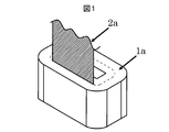
- FIG. 1 is a perspective view showing an embodiment of a method for annealing an amorphous iron core according to the present invention, in which a heat source is sandwiched between iron cores.
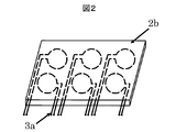
- FIG. 2 is a detailed perspective view showing an example of a heat source using induction heating used in the annealing method shown in FIG.
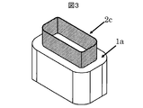
- FIG. 3 is a perspective view showing another embodiment of the method for annealing an amorphous iron core according to the present invention in a form in which a heat source is sandwiched between iron cores.
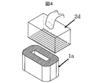
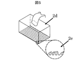
- FIG. 4 is a perspective view showing an embodiment in which the temperature is raised from the end face of the laminated layer in the method for annealing an amorphous core according to the present invention.
- FIG. 1 is a perspective view showing an embodiment of a method for annealing an amorphous iron core according to the present invention, in which a heat source is sandwiched between iron cores.
- FIG. 2 is a detailed perspective view showing an example of a heat source using in
- FIG. 5 shows a detailed view of a heat source as an example of the heat source used in FIG.
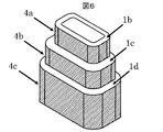
- FIG. 6 is a perspective view showing a state in which the iron core is extended in a plurality of stages in a direction perpendicular to the laminated end surface in the method for annealing an amorphous iron core according to the present invention.
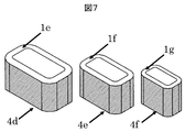
- FIG. 7 is a perspective view showing a state in which a plurality of cores are divided in the stacking direction in the method for annealing an amorphous core according to the present invention.
- FIG. 1 is a perspective view showing a first embodiment in which an amorphous core 1a is annealed, and shows a state in which a heater 2a is sandwiched between amorphous cores 1a formed by laminating a large number of amorphous materials (thin film materials). Yes.
- the heater 2a may be a heater such as an iron thin plate that directly heats 2a itself in FIG.
- the heater 2a is preferably a material that can withstand an annealing temperature of 400 ° C.
- n-th layer amorphous material includes an n-th layer amorphous material and an n + 1-th layer amorphous material from the innermost peripheral side of the iron core 1a. It is placed between them and heated by an external heat source to carry heat for annealing between the two amorphous layers.
- FIG. 2 shows a heater 2b using the principle of induction heating (IH heating) as a second embodiment of the method for annealing an amorphous iron core.
- the heater 2b is an alternative example of the heater 2a, and heats the iron core itself using induction heating.
- the heater 2b produces a plurality of one-turn or several-turn induction coils using a wire 3a or the like in a material that can withstand an annealing temperature of 400 ° C. or higher.
- the amount of heat applied to the iron core 1a can be adjusted by the voltage applied to each induction coil and the number of turns of the coil.
- FIG. 3 is an explanatory view showing a third embodiment of the method for annealing an amorphous iron core according to the present invention.
- FIG. 3 shows a state in which a cylindrical heat transfer material 2c is sandwiched between amorphous iron cores 1a made of an amorphous material.
- the heat transfer material 2c is a heat transfer material made of a copper plate or the like for transferring heat to the central part of the amorphous core of the iron core 1a, and can withstand, for example, an annealing temperature of 400 ° C. or more, and has a thermal conductivity of 25 w / m ⁇ Substances of K or higher are preferred.
- the heat transfer material 2c is arranged between the n (n is an integer of 2 or more) layer amorphous material and the n + 1 layer amorphous material from the innermost peripheral side of the iron core 1a, and is formed in a cylindrical shape. Therefore, it is possible to ensure a sufficient contact / heat conduction surface area with both amorphous layers.
- the heat transfer material 2c sandwiched between the amorphous materials of the iron core 1a serves to transmit the external temperature between the amorphous materials during annealing, and adjusts the temperature distribution in the iron core 1a.
- heat amount which the heat-transfer material 2c gives to the iron core 1a it can adjust with the stack thickness, board width, and heat conductivity of the heat-transfer material 2c.
- the number of the heat transfer materials 2c can also be increased according to the size of the iron core 1a, similarly to the number of the heaters 2a and 2b.
- FIG. 4 is a view showing that the laminated end face of the amorphous iron core 1a is heated by the heater 2d
- FIG. 5 is an enlarged view of a part of the heating surface portion of the heater 2d showing the surface state.
- Amorphous iron core has a lower space factor than electrical steel sheets, and since there are many air layers between layers, heat transfer between layers is expected to be low. Therefore, by applying heat from the laminated end face of the amorphous thin material by the heater 2d, heat can be efficiently transferred to the individual iron cores to each amorphous thin material. As a result, the annealing time can be shortened.
- the heating surface of the heater 2d can be made of a material such as metal fiber, carbon fiber or carbon nanotube, or a gel material. By providing such a fibrous heating surface, the heater 2d can secure a contact area with the laminated end surface of the amorphous iron core 1a in a substantial sense.
- FIG. 6 shows a state in which the iron core is extended in several stages so that the temperature raising condition in the iron core does not change during annealing
- FIG. 7 shows a state in which the iron core is divided into several parts with respect to the laminated surface.
- the amorphous iron core has a low heat transfer between the laminated layers, and when annealed, there is a difference in temperature between the outside and the center of the iron core.
- the iron core is extended in several steps (two or more steps) in the direction perpendicular to the laminated surface.
- a method for further suppressing the temperature difference between the outside and the center of the iron core there is a method of annealing by dividing the iron core into several parts (22 steps or more) with respect to the laminated surface as shown in FIG.
- a material that can withstand an annealing temperature of 400 ° C. or more is wound around the outermost and innermost circumferences of the divided iron cores, and the iron core is fixed.
- all the divided cores are annealed under the same conditions, and the magnetoresistive distribution is changed by annealing each of the divided cores under different conditions separately from the effect of suppressing unevenness of the annealing temperature in the core.
- annealing of an amorphous material is performed in a magnetic field, it is desirable to use a nonmagnetic material that does not affect the magnetic field.
- annealing of the amorphous material be performed at ambient temperature. However, when heat is supplied from the laminated surface, the annealing is not necessarily performed at ambient temperature.
Landscapes
- Chemical & Material Sciences (AREA)
- Engineering & Computer Science (AREA)
- Physics & Mathematics (AREA)
- Materials Engineering (AREA)
- Crystallography & Structural Chemistry (AREA)
- Organic Chemistry (AREA)
- Mechanical Engineering (AREA)
- Metallurgy (AREA)
- Thermal Sciences (AREA)
- Power Engineering (AREA)
- Electromagnetism (AREA)
- Manufacturing & Machinery (AREA)
- Inorganic Chemistry (AREA)
- Dispersion Chemistry (AREA)
- Manufacturing Cores, Coils, And Magnets (AREA)
- Heat Treatment Of Articles (AREA)
Priority Applications (3)
| Application Number | Priority Date | Filing Date | Title |
|---|---|---|---|
| EP11739616.8A EP2533259A4 (en) | 2010-02-04 | 2011-01-18 | GLOWING PROCESS FOR AMORPHE KERNEL |
| CN201180008356.4A CN102741957B (zh) | 2010-02-04 | 2011-01-18 | 非晶铁芯的退火方法 |
| US13/576,254 US20130000795A1 (en) | 2010-02-04 | 2011-01-18 | Amorphous Core Annealing Method |
Applications Claiming Priority (2)
| Application Number | Priority Date | Filing Date | Title |
|---|---|---|---|
| JP2010023224A JP2011165701A (ja) | 2010-02-04 | 2010-02-04 | アモルファス鉄心の焼鈍方法 |
| JP2010-023224 | 2010-09-28 |
Publications (1)
| Publication Number | Publication Date |
|---|---|
| WO2011096267A1 true WO2011096267A1 (ja) | 2011-08-11 |
Family
ID=44355273
Family Applications (1)
| Application Number | Title | Priority Date | Filing Date |
|---|---|---|---|
| PCT/JP2011/050692 Ceased WO2011096267A1 (ja) | 2010-02-04 | 2011-01-18 | アモルファス鉄心の焼鈍方法 |
Country Status (6)
| Country | Link |
|---|---|
| US (1) | US20130000795A1 (enExample) |
| EP (1) | EP2533259A4 (enExample) |
| JP (1) | JP2011165701A (enExample) |
| CN (1) | CN102741957B (enExample) |
| TW (1) | TWI443198B (enExample) |
| WO (1) | WO2011096267A1 (enExample) |
Families Citing this family (8)
| Publication number | Priority date | Publication date | Assignee | Title |
|---|---|---|---|---|
| JP2013029669A (ja) | 2011-07-28 | 2013-02-07 | Kyocera Document Solutions Inc | 画像形成装置 |
| CN104252967B (zh) * | 2014-06-25 | 2017-02-15 | 上海置信电气非晶有限公司 | 一种非晶合金立体卷铁心的热处理的控制方法 |
| JP6272185B2 (ja) * | 2014-08-25 | 2018-01-31 | 三菱電機株式会社 | 配線用コア構造、半導体評価装置及び半導体装置 |
| CN104616881B (zh) * | 2014-12-30 | 2016-09-28 | 安泰南瑞非晶科技有限责任公司 | 配电变压器用铁基非晶合金铁心及其制造方法 |
| JP7059102B2 (ja) * | 2018-05-14 | 2022-04-25 | 株式会社三井ハイテック | 積層体の製造方法 |
| JP7192511B2 (ja) * | 2019-01-10 | 2022-12-20 | トヨタ自動車株式会社 | 合金薄帯の製造方法 |
| JP7088057B2 (ja) * | 2019-02-06 | 2022-06-21 | トヨタ自動車株式会社 | 合金薄帯の製造方法 |
| CN113667801B (zh) * | 2020-07-28 | 2022-05-03 | 山东大学 | 一种非晶合金的热处理方法 |
Citations (5)
| Publication number | Priority date | Publication date | Assignee | Title |
|---|---|---|---|---|
| JPS62154710A (ja) * | 1985-12-27 | 1987-07-09 | Toshiba Corp | 巻鉄心の製造方法 |
| JPH08227816A (ja) | 1995-10-24 | 1996-09-03 | Hitachi Ltd | 非晶質巻鉄心 |
| JPH1022145A (ja) | 1996-07-05 | 1998-01-23 | Hitachi Ltd | アモルファス変圧器及びその製造方法 |
| JP2004014601A (ja) | 2002-06-04 | 2004-01-15 | Hitachi Metals Ltd | 環状コアの熱処理方法 |
| JP2008285746A (ja) | 2007-04-20 | 2008-11-27 | Hitachi Industrial Equipment Systems Co Ltd | 鉄心焼鈍炉 |
Family Cites Families (6)
| Publication number | Priority date | Publication date | Assignee | Title |
|---|---|---|---|---|
| JPS60233811A (ja) * | 1984-04-27 | 1985-11-20 | Toshiba Corp | 巻鉄心の熱処理方法 |
| JPS6158222A (ja) * | 1984-08-30 | 1986-03-25 | Toshiba Corp | 静止誘導電器の製造方法 |
| JPS6159812A (ja) * | 1984-08-31 | 1986-03-27 | Toshiba Corp | 鉄心の製造方法 |
| JPH01161815A (ja) * | 1987-12-18 | 1989-06-26 | Toshiba Corp | 巻鉄心の製造方法 |
| JPH0684655A (ja) * | 1992-09-01 | 1994-03-25 | Toshiba Corp | 高周波用巻鉄心及び該巻鉄心を用いた高周波用誘導電気機器 |
| TW200825184A (en) * | 2006-12-13 | 2008-06-16 | Tatung Co Ltd | The annealing method for amorphous iron cores and system thereof |
-
2010
- 2010-02-04 JP JP2010023224A patent/JP2011165701A/ja active Pending
-
2011
- 2011-01-18 US US13/576,254 patent/US20130000795A1/en not_active Abandoned
- 2011-01-18 CN CN201180008356.4A patent/CN102741957B/zh not_active Expired - Fee Related
- 2011-01-18 WO PCT/JP2011/050692 patent/WO2011096267A1/ja not_active Ceased
- 2011-01-18 EP EP11739616.8A patent/EP2533259A4/en not_active Withdrawn
- 2011-01-21 TW TW100102326A patent/TWI443198B/zh not_active IP Right Cessation
Patent Citations (5)
| Publication number | Priority date | Publication date | Assignee | Title |
|---|---|---|---|---|
| JPS62154710A (ja) * | 1985-12-27 | 1987-07-09 | Toshiba Corp | 巻鉄心の製造方法 |
| JPH08227816A (ja) | 1995-10-24 | 1996-09-03 | Hitachi Ltd | 非晶質巻鉄心 |
| JPH1022145A (ja) | 1996-07-05 | 1998-01-23 | Hitachi Ltd | アモルファス変圧器及びその製造方法 |
| JP2004014601A (ja) | 2002-06-04 | 2004-01-15 | Hitachi Metals Ltd | 環状コアの熱処理方法 |
| JP2008285746A (ja) | 2007-04-20 | 2008-11-27 | Hitachi Industrial Equipment Systems Co Ltd | 鉄心焼鈍炉 |
Non-Patent Citations (1)
| Title |
|---|
| See also references of EP2533259A4 |
Also Published As
| Publication number | Publication date |
|---|---|
| TW201144450A (en) | 2011-12-16 |
| TWI443198B (zh) | 2014-07-01 |
| EP2533259A1 (en) | 2012-12-12 |
| EP2533259A4 (en) | 2016-07-13 |
| JP2011165701A (ja) | 2011-08-25 |
| CN102741957B (zh) | 2014-11-26 |
| US20130000795A1 (en) | 2013-01-03 |
| CN102741957A (zh) | 2012-10-17 |
Similar Documents
| Publication | Publication Date | Title |
|---|---|---|
| WO2011096267A1 (ja) | アモルファス鉄心の焼鈍方法 | |
| JP6517844B2 (ja) | アモルファス合金薄帯の積層体の熱処理装置および軟磁性コア | |
| CN105009688B (zh) | 感应加热线圈以及使用了该感应加热线圈的感应加热装置 | |
| KR102009746B1 (ko) | 냉각효율을 높힌 변압기용 권선코일의 제조방법 | |
| US11244782B2 (en) | Amorphous alloy magnetic core | |
| US11562856B2 (en) | Method for manufacturing alloy ribbon | |
| WO2017107129A1 (zh) | 穿绕硅钢带磁芯的电力变压器及其制作方法 | |
| JP2009295443A (ja) | 誘導コイル及び電磁誘導加熱装置 | |
| WO2006112564A1 (en) | Transformer having multi -layered winding structure | |
| JPS6366045B2 (enExample) | ||
| US12283411B2 (en) | Method for crystallization heat treating a stack of amorphous alloy ribbons | |
| JP2007180135A (ja) | 変圧器 | |
| JPS61179517A (ja) | 静止誘導電器の製造方法 | |
| JP2010278322A (ja) | チョークコイル | |
| JPS6159812A (ja) | 鉄心の製造方法 | |
| JPS61179507A (ja) | 鉄心の製造方法 | |
| JPS6140016A (ja) | 鉄心の製造方法 | |
| CN107275049A (zh) | 一种改善电力变压器热稳定性的方法 | |
| JPS5927507A (ja) | 非晶質合金薄帯を用いたトランス用鉄芯の焼鈍方法 | |
| JP2002129243A (ja) | 円筒状金属コイルの加熱方法 | |
| JPS61179519A (ja) | 鉄心の製造方法 | |
| JPS6252912A (ja) | 鉄心の焼鈍方法 | |
| JPS6222413A (ja) | 鉄心の製造方法 | |
| JPH01161815A (ja) | 巻鉄心の製造方法 | |
| KR20070070747A (ko) | 변압기용 코어의 소둔 장치 및 그 방법 |
Legal Events
| Date | Code | Title | Description |
|---|---|---|---|
| WWE | Wipo information: entry into national phase |
Ref document number: 201180008356.4 Country of ref document: CN |
|
| 121 | Ep: the epo has been informed by wipo that ep was designated in this application |
Ref document number: 11739616 Country of ref document: EP Kind code of ref document: A1 |
|
| WWE | Wipo information: entry into national phase |
Ref document number: 2011739616 Country of ref document: EP |
|
| WWE | Wipo information: entry into national phase |
Ref document number: 6779/DELNP/2012 Country of ref document: IN |
|
| NENP | Non-entry into the national phase |
Ref country code: DE |
|
| WWE | Wipo information: entry into national phase |
Ref document number: 13576254 Country of ref document: US |