WO2011087306A9 - Appareil d'imagerie par tomographie informatisée à rayons x et procédé s'y rapportant - Google Patents
Appareil d'imagerie par tomographie informatisée à rayons x et procédé s'y rapportant Download PDFInfo
- Publication number
- WO2011087306A9 WO2011087306A9 PCT/KR2011/000267 KR2011000267W WO2011087306A9 WO 2011087306 A9 WO2011087306 A9 WO 2011087306A9 KR 2011000267 W KR2011000267 W KR 2011000267W WO 2011087306 A9 WO2011087306 A9 WO 2011087306A9
- Authority
- WO
- WIPO (PCT)
- Prior art keywords
- magnification
- image
- camera
- subject
- detector
- Prior art date
Links
- 238000000034 method Methods 0.000 title claims abstract description 39
- 238000003384 imaging method Methods 0.000 title claims abstract description 19
- 238000003325 tomography Methods 0.000 claims abstract description 24
- 230000001678 irradiating effect Effects 0.000 claims description 8
- 230000033001 locomotion Effects 0.000 claims description 3
- 238000012545 processing Methods 0.000 description 12
- 238000013480 data collection Methods 0.000 description 8
- 238000010586 diagram Methods 0.000 description 7
- 230000005540 biological transmission Effects 0.000 description 6
- 238000002591 computed tomography Methods 0.000 description 5
- 230000000694 effects Effects 0.000 description 4
- 238000001514 detection method Methods 0.000 description 3
- 238000012986 modification Methods 0.000 description 2
- 230000004048 modification Effects 0.000 description 2
- 230000003044 adaptive effect Effects 0.000 description 1
- 238000013170 computed tomography imaging Methods 0.000 description 1
- 230000003247 decreasing effect Effects 0.000 description 1
- 238000002474 experimental method Methods 0.000 description 1
- 238000001914 filtration Methods 0.000 description 1
- 230000003287 optical effect Effects 0.000 description 1
- 238000001356 surgical procedure Methods 0.000 description 1
- 238000012360 testing method Methods 0.000 description 1
Images


Classifications
-
- A—HUMAN NECESSITIES
- A61—MEDICAL OR VETERINARY SCIENCE; HYGIENE
- A61B—DIAGNOSIS; SURGERY; IDENTIFICATION
- A61B6/00—Apparatus for radiation diagnosis, e.g. combined with radiation therapy equipment
- A61B6/02—Devices for diagnosis sequentially in different planes; Stereoscopic radiation diagnosis
- A61B6/03—Computerised tomographs
-
- A61B6/51—
-
- A—HUMAN NECESSITIES
- A61—MEDICAL OR VETERINARY SCIENCE; HYGIENE
- A61B—DIAGNOSIS; SURGERY; IDENTIFICATION
- A61B6/00—Apparatus for radiation diagnosis, e.g. combined with radiation therapy equipment
- A61B6/02—Devices for diagnosis sequentially in different planes; Stereoscopic radiation diagnosis
- A61B6/03—Computerised tomographs
- A61B6/032—Transmission computed tomography [CT]
-
- A—HUMAN NECESSITIES
- A61—MEDICAL OR VETERINARY SCIENCE; HYGIENE
- A61B—DIAGNOSIS; SURGERY; IDENTIFICATION
- A61B6/00—Apparatus for radiation diagnosis, e.g. combined with radiation therapy equipment
- A61B6/44—Constructional features of apparatus for radiation diagnosis
- A61B6/4429—Constructional features of apparatus for radiation diagnosis related to the mounting of source units and detector units
- A61B6/4452—Constructional features of apparatus for radiation diagnosis related to the mounting of source units and detector units the source unit and the detector unit being able to move relative to each other
-
- A—HUMAN NECESSITIES
- A61—MEDICAL OR VETERINARY SCIENCE; HYGIENE
- A61B—DIAGNOSIS; SURGERY; IDENTIFICATION
- A61B6/00—Apparatus for radiation diagnosis, e.g. combined with radiation therapy equipment
- A61B6/54—Control of apparatus or devices for radiation diagnosis
- A61B6/545—Control of apparatus or devices for radiation diagnosis involving automatic set-up of acquisition parameters
-
- A—HUMAN NECESSITIES
- A61—MEDICAL OR VETERINARY SCIENCE; HYGIENE
- A61B—DIAGNOSIS; SURGERY; IDENTIFICATION
- A61B6/00—Apparatus for radiation diagnosis, e.g. combined with radiation therapy equipment
- A61B6/58—Testing, adjusting or calibrating apparatus or devices for radiation diagnosis
- A61B6/582—Calibration
-
- A—HUMAN NECESSITIES
- A61—MEDICAL OR VETERINARY SCIENCE; HYGIENE
- A61B—DIAGNOSIS; SURGERY; IDENTIFICATION
- A61B6/00—Apparatus for radiation diagnosis, e.g. combined with radiation therapy equipment
- A61B6/58—Testing, adjusting or calibrating apparatus or devices for radiation diagnosis
- A61B6/588—Setting distance between source unit and detector unit
Definitions
- the present invention relates to an X-ray tomography apparatus and an image photographing method, and more particularly, to an X-ray tomography apparatus and an image photographing method for photographing a subject at an optimal magnification.
- an X-ray tomography apparatus includes an X-ray tube for scanning X-rays to a subject, a detector for detecting X-rays passing through the subject, a rotating mechanism unit equipped with the X-ray tube and a detector to rotate, and the detector from the detector. And a computer device for reconstructing the obtained data into image information.
- the general X-ray tomography apparatus having the above configuration photographs the tomography of the subject while the rotating mechanism rotates about the subject.
- the tomography of the subject is performed at predetermined micro-angles, and the projection data of the X-rays obtained by photographing at the predetermined micro-angles is subjected to mathematical operations such as repeated reconstruction, reverse projection reconstruction, and filtration reverse projection reconstruction. It is reconstructed with the section image information.
- dental CT (Computed Tomography) is an X-ray tube and X-rays arranged on the left and right sides of a subject to professionally diagnose only a part of a patient's head, neck, jaw, and teeth in dental and oral surgery.
- the detector is a device that obtains transmission information while rotating in parallel with the ground.
- the present invention provides an X-ray tomography apparatus and method for acquiring an image at an optimal magnification according to a field of view (FOV) and a size of a voxel.
- FOV field of view
- the present invention includes: an imaging device for irradiating light to a subject and detecting the light transmitted through the subject; An enlargement ratio determiner configured to determine an enlargement ratio of an image of the subject by using at least one of a hardware attribute of the camera and a size of an input voxel; And an magnification controller for moving the camera to correspond to the determined magnification.
- the magnification determining unit may include: a first magnification determining unit configured to determine a first magnification ratio based on hardware attributes of the camera; A second magnification determining unit which determines a second magnification based on the size of the voxel; And a third magnification determining unit configured to determine a value between the first magnification ratio and the second magnification ratio as an magnification ratio of an image of the subject.
- the hardware attribute includes at least one of focal size, pixel size, and resolution of the camera.
- the imaging device may include a light source for irradiating the light onto the subject; And a detector for detecting the light that has passed through the subject.
- the magnification controller controls movement of at least one of the light source and the detector to correspond to the determined magnification.
- the X-ray tomography apparatus further includes an image reconstructing unit configured to reconstruct an image of the subject into a 3D image by using a variable filter panoramic reverse projection method.
- variable filter panoramic reverse projection method an image obtained by the camera is projected back about a virtual rotation axis which is a rotation axis based on the light receiving surfaces of the detector in the camera, and the filter is different according to the distance between the virtual rotation axis and the detector.
- the image is corrected and reconstructed by applying a value.
- the camera is any one of a dental camera, a head and neck camera, an otolaryngology camera.
- the present invention provides a method for determining an enlargement ratio of an image of a subject by using at least one of a hardware attribute of an imager that irradiates light to the subject and detects the light that has passed through the subject, and a size of an input voxel. step; Moving the camera to correspond to the determined magnification; And acquiring an image of the subject while rotating the moved imaging device.
- the determining of the magnification may include determining a first magnification based on hardware attributes of the camera; Determining a second magnification ratio based on the size of the voxel; And determining a value between the first magnification ratio and the second magnification ratio as an enlargement ratio of an image of the subject.
- the hardware attribute includes at least one of focal size, pixel size, and resolution of the camera.
- the moving of the camera may include moving at least one of the light source and the detector to correspond to the determined magnification.
- the camera is any one of a dental camera, a head and neck camera, an otolaryngology camera.
- the resolution is increased, the signal to noise ratio is increased, and the aliasing artifacts are reduced compared to the existing image.
- FIG. 1 is a block diagram of an X-ray tomography apparatus according to an embodiment of the present invention.
- FIG. 2 is a block diagram of a magnification determining unit in a data processing apparatus for determining an optimal magnification for an image according to an embodiment of the present invention
- FIG. 3 is a reference diagram for explaining an operation of a first magnification determining unit according to an embodiment of the present invention
- FIG. 4 is a cross-sectional view of an X-ray tomography apparatus movable a detector according to an embodiment of the present invention
- FIG. 5 is a view showing a cross-sectional view of the X-ray tomography apparatus movable the imager according to an embodiment of the present invention
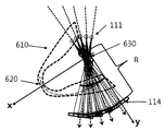
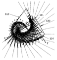
- FIGS. 6 and 7 are views for explaining a virtual rotating shaft according to an embodiment of the present invention.
- FIG. 8 is a flowchart illustrating a method of capturing an image according to an enlargement ratio according to an embodiment of the present invention.
- An X-ray tomography apparatus includes an imager for irradiating light to a subject and detecting the light transmitted through the subject; An enlargement ratio determiner configured to determine an enlargement ratio of an image of the subject by using at least one of a hardware attribute of the camera and a size of an input voxel; And a magnification controller for moving the camera to correspond to the determined magnification.
- the object is scanned using at least one of a hardware attribute of an imager that detects the light that has passed through the subject and the size of the input voxel. Determining an enlargement ratio of the image for the specimen; Moving the camera to correspond to the determined magnification; And acquiring an image of the subject while rotating the moved camera.
- FIG. 1 is a block diagram of an X-ray tomography apparatus according to an embodiment of the present invention.
- the X-ray tomography apparatus includes a scan gantry 10, an imaging table 30, and an operation console 50.
- the imaging table 30 is comprised so that a subject (not shown) may be conveyed in and out of the light emission space in the scanning gantry 10.
- the operation console 50 may include a data collection buffer 153 for temporarily storing digital data provided from the data collection unit 115, and digital data for a plurality of views collected through the data collection buffer 153.
- a data processing device 151 for reconstructing a 3D image using the display a display device 155 for displaying a 3D image, and the data processing device 151 on the rotating body 116 and the rotating body 116.
- the light source 111, the light source controller 112, the detector 114, and the data collector 115 are mounted on the rotating body 116 to rotate under the control of the rotation controller. That is, the rotating body 116 mounted with each component rotates at a slight angular interval around the subject to continuously obtain transmission information (tomographic image information), that is, a detection signal at each position.
- transmission information tomographic image information
- the light source 111 generates a predetermined light under the control of the light source controller 112 to emit toward the subject.
- the emitted light is transmitted to the detector 114 through the subject.
- Signals detected by individual detection elements in the detector 114 ie digital data, are collected by the data collector 115.
- the light source 111 and the detector 114 may be referred to as a photographing apparatus because the photographing object is a subject, and the photographing apparatus may be any one of a dental photographing apparatus, a head photographing apparatus, and an otolaryngology imaging apparatus.
- the scanning gantry includes an enlargement ratio controller 113 for adjusting the enlargement ratio by moving the photographing apparatus.
- the data collector 115 converts a series of voltage signals generated according to the amount of light detected by the detector 114 into digital data. Digital data, which is tomographic image information, is transferred to the data collection buffer 153. Then, the data acquisition buffer 153 transmits the incoming digital data to the data processing device 151 in order.
- the user sets the field of view (FOV) and the size of the voxel of the subject to be photographed using the manipulation device 156, and the data processing device 151 determines the magnification ratio suitable for the size of the set FOV and the voxel. It demonstrates concretely below.
- FIG. 2 is a block diagram of a magnification determining unit in a data processing apparatus for determining an optimal magnification for an image according to an embodiment of the present invention.
- the data processing apparatus 151 may determine a first magnification ratio 210 that determines a first magnification ratio based on a hardware attribute of the camera, and determines a second magnification ratio based on the size of a voxel.
- the second magnification determining unit 220 and the third magnification determining unit 230 determine an optimal magnification of the image based on the first magnification and the second magnification.
- the hardware attribute may include at least one of a focal size of the light source 111, a pixel size of the detector 114, and a resolution of the detector 114.
- the hardware attribute may include a focal size, a pixel, and the like. Assume both magnitude and detector 114 resolution.
- FIG. 3 is a reference diagram for describing an operation of a first magnification determining unit according to an embodiment of the present invention.
- the focal size f, the magnification M, and the spatial frequency u are expressed as in Equation 1 below.
- the pixel size (d), the magnification (M), and the spatial frequency (u) can be expressed by the following equation (2).
- the detector resolution that is, the sensor resolution (b), the magnification (M), and the spatial frequency (u) can be expressed by the following equation (3).
- the first magnification determining unit 210 recognizes the curves and the straight lines shown in FIG. 3. In other words, the first magnification determining unit 210 previously stores spatial frequency and magnification relationship information of each pixel size, sensor resolution, and focus size. The first magnification determining unit 210 determines a minimum value among spatial frequencies corresponding to the pixel size, the sensor resolution, and the focusing size for each magnification. The determined minimum value is the value on the curve MF indicated by the dotted line in FIG. 3. The first magnification determination unit 210 determines the magnification M at the maximum spatial frequency among the determined minimum values, that is, the spatial frequency on the curve MF as the first magnification ratio.
- the second magnification determining unit 220 determines the second magnification ratio Pm through Equation 4 based on the size of the voxel.
- d is the size of the pixel and Ev is the size of the voxel.
- the third magnification determining unit 230 determines a value between the first magnification ratio and the second magnification ratio as the optimal third magnification ratio.
- the third magnification may be an average value of the first magnification and the second magnification.
- the third magnification determining unit 230 determines an optimal third magnification ratio according to the FOV, the size and type of the detector 114, and may determine the optimum third magnification ratio based on the reference data.
- the reference data may be an optimal third magnification ratio obtained by an experiment according to the FOV, the size of the detector 114, the type of the detector 114, and the like.
- the magnification controller 113 controls the photographing apparatus according to the magnification determined by the third magnification determining unit 230. Specifically, the magnification is (distance between the light source 111 and the detector 114) / (distance between the light source 111 and the object under test). Thus, the magnification controller 113 moves the imaging device to the determined magnification.
- FIG. 4 is a cross-sectional view of an X-ray tomography apparatus movable a detector according to an embodiment of the present invention.
- the member 430 having the detector 114 attached to the rotation axis 410 of the rotating body 116 is movable in the horizontal direction.
- the magnification controller 113 moves the detector 114 left and right so as to have a determined magnification.
- FIG. 5 is a diagram illustrating a cross-sectional view of an X-ray tomography apparatus which can move a camera according to an embodiment of the present invention.
- the member to which the camera is attached is movable in the horizontal direction.
- the camera is moved left and right so as to have a determined magnification ratio.
- the optimal magnification is determined according to the FOV and the size of the voxel, and the subject is photographed at the determined magnification, so that the resolution is increased compared to the existing image, the signal to noise ratio is increased, and the aliasing artifact (Aliasing artifact) is reduced.
- the image reconstruction unit (not shown) of the data processing device 151 may transmit a 3D image reconstructed through the image reconstruction algorithm, that is, the object transmission information (tomographic information) transmitted from the data collection buffer 153. Acquire.
- the image reconstruction unit may reconstruct a 3D image using a variable filtered panoramic back projection method. That is, each obtained image is projected backward with respect to the virtual rotation axis, and the filter value according to the distance R between the virtual rotation axis and the detector 114 is calculated and applied.
- the virtual rotation axis refers to a rotation axis based on the light receiving surfaces of the detector 114 in which light is detected. Since the distance R between the virtual rotation axis and the detector 114 is always changed, a filter value is also applied differently. shall.
- FIGS. 6 and 7 are views for explaining a virtual rotary shaft according to an embodiment of the present invention.
- the subject is positioned between a light source 111 for irradiating light to an image layer located in a region of interest of the subject and a detector 114 for detecting light transmitted through the image layer. .
- X-rays are irradiated to the viewpoint of the image layer to acquire an image of the viewpoint portion of the image layer.
- the light source 111 and the detector 114 are moved along the first trajectory to continuously photograph the next part of the image layer, and the virtual rotation axis is moved along the second trajectory different from the first trajectory. Let's do it.
- the light source 111 and the detector 114 continuously irradiate and detect light while moving. Further, the distance R between the virtual axis of rotation and the light receiving surface of the detector 114 continues to change.
- the present invention may acquire an image while driving the light source 111 and the detector 114 as a new trajectory in which the trajectory according to the panoramic imaging method and the trajectory according to the CT imaging method are combined. This simplifies the shooting trajectory and shortens the shooting time, but has an effect of obtaining a three-dimensional image in the form of arch.
- the data processing apparatus 151 reconstructs the 3D image by using an adaptive filtered panoramic back projection method.
- variable filter panoramic reverse projection method has the same basic principle as the general reverse projection method of reconstructing an image by filling the obtained frame image in three dimensions according to the irradiation direction up to the focal point of the light source 111 and filling all the frames with overlap. .
- the reverse projection rotational position according to the position of the rotating shaft of the rotating body 116 is matched and blurring.
- the reconstruction that corrects the image by calculating each filter value according to the distance because the distance R between the virtual axis of rotation and the detector 114 is not fixed but variable when designing a filter for removing artifacts. It means the way.
- the above-described filter whose filter value changes as the distance R between the virtual rotary shaft and the detector 114 is not fixed but is changed is called a variable filter.
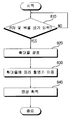
- FIG. 8 is a flowchart illustrating a method of capturing an image according to an enlargement ratio according to an embodiment of the present invention.
- the enlargement rate determining unit determines the enlargement ratio according to the sizes of the FOV and the voxels (S820).
- the first magnification determining unit 210 determines the first magnification in consideration of hardware attributes (eg, focal size, pixel size, and sensor resolution) of the camera.
- the second magnification determining unit 220 determines the second magnification based on the size of the voxel.
- the third magnification determining unit 230 determines the final magnification based on the first magnification and the second magnification.
- the determined magnification ratio is transmitted to the magnification controller 113 through the control interface 152, and the magnification controller 113 moves the camera so that the photographer photographs the subject at the magnification mentioned above (S830).
- the magnification controller 113 moves the camera so that the photographer photographs the subject at the magnification mentioned above (S830).
- the detector 114 may be moved in the horizontal direction while the light source 111 is fixed, or both the light source 111 and the detector 114 may be moved.
- a program for executing a high resolution panoramic image acquisition method according to at least one embodiment of the present invention mentioned above on a computer may be stored in a computer readable recording medium.
- the computer-readable recording medium may be a magnetic storage medium (for example, a ROM, a floppy disk, a hard disk, etc.), and an optical reading medium (for example, a CD-ROM, a DVD) DVD: Digital Versatile Disc).
Abstract
L'invention concerne un appareil d'imagerie par tomographie informatisée à rayons X ainsi qu'un procédé s'y rapportant. L'appareil d'imagerie par tomographie informatisée à rayons X de la présente invention comprend : un tomographe qui émet de la lumière sur un objet imagé par tomographie, et détecte la lumière passant à travers l'objet imagé par tomographie ; une unité de définition du taux d'agrandissement qui détermine le taux d'agrandissement d'une image de l'objet imagé par tomographie en utilisant les propriétés matérielles du tomographe et/ou la taille d'un voxel d'entrée ; et une unité de commande du taux d'agrandissement qui déplace la tomographie en fonction du taux d'agrandissement déterminé, permettant ainsi d'obtenir des images ayant une résolution élevée.
Priority Applications (3)
| Application Number | Priority Date | Filing Date | Title |
|---|---|---|---|
| EP11733093.6A EP2508133B1 (fr) | 2010-01-13 | 2011-01-13 | Appareil d'imagerie par tomographie informatisée à rayons x et procédé s'y rapportant |
| US13/521,926 US9532755B2 (en) | 2010-01-13 | 2011-01-13 | X-ray computed tomographic imaging apparatus and method for same |
| JP2012548890A JP5784040B2 (ja) | 2010-01-13 | 2011-01-13 | X線断層撮影装置及びその方法 |
Applications Claiming Priority (2)
| Application Number | Priority Date | Filing Date | Title |
|---|---|---|---|
| KR10-2010-0003220 | 2010-01-13 | ||
| KR1020100003220A KR101190801B1 (ko) | 2010-01-13 | 2010-01-13 | X선 단층 촬영 장치 및 그 방법 |
Publications (3)
| Publication Number | Publication Date |
|---|---|
| WO2011087306A2 WO2011087306A2 (fr) | 2011-07-21 |
| WO2011087306A9 true WO2011087306A9 (fr) | 2011-10-20 |
| WO2011087306A3 WO2011087306A3 (fr) | 2011-12-08 |
Family
ID=44304828
Family Applications (1)
| Application Number | Title | Priority Date | Filing Date |
|---|---|---|---|
| PCT/KR2011/000267 WO2011087306A2 (fr) | 2010-01-13 | 2011-01-13 | Appareil d'imagerie par tomographie informatisée à rayons x et procédé s'y rapportant |
Country Status (5)
| Country | Link |
|---|---|
| US (1) | US9532755B2 (fr) |
| EP (1) | EP2508133B1 (fr) |
| JP (1) | JP5784040B2 (fr) |
| KR (1) | KR101190801B1 (fr) |
| WO (1) | WO2011087306A2 (fr) |
Families Citing this family (9)
| Publication number | Priority date | Publication date | Assignee | Title |
|---|---|---|---|---|
| KR101501516B1 (ko) | 2012-01-09 | 2015-03-11 | 삼성메디슨 주식회사 | 촬영된 영상의 확대 영상과 휘도 정보를 이용하여 촬영된 대상체를 메저링하기 위한 방법 및 그 장치 |
| KR101401927B1 (ko) * | 2012-06-29 | 2014-05-30 | 주식회사 덴티움 | 치과용 파노라마 및 씨티 겸용 x선 촬영장치 |
| KR102060659B1 (ko) | 2013-03-20 | 2019-12-30 | 삼성전자주식회사 | 영상 처리를 위한 투사 및 역투사 방법 및 그 영상 처리 장치 |
| WO2015026165A1 (fr) * | 2013-08-20 | 2015-02-26 | 주식회사바텍 | Dispositif d'imagerie radiographique et procédé d'imagerie radiographique |
| KR102285553B1 (ko) * | 2014-07-29 | 2021-08-05 | 주식회사 바텍 | 2차원 단층 영상 촬영장치 및 그 방법 |
| JP6666283B2 (ja) | 2017-02-23 | 2020-03-13 | 株式会社モリタ製作所 | X線断層撮影装置およびx線断層撮影方法 |
| JP6837400B2 (ja) * | 2017-08-23 | 2021-03-03 | 株式会社モリタ製作所 | X線撮影装置及びx線撮影方法 |
| KR102043357B1 (ko) * | 2017-10-18 | 2019-11-12 | 오스템임플란트 주식회사 | 영상 확대율 변경 방법 및 장치 |
| JP6837452B2 (ja) | 2018-04-27 | 2021-03-03 | 株式会社モリタ製作所 | X線ct撮影装置及びx線ct撮影装置の制御方法 |
Family Cites Families (17)
| Publication number | Priority date | Publication date | Assignee | Title |
|---|---|---|---|---|
| JP2003116837A (ja) * | 1992-04-01 | 2003-04-22 | Sony Corp | 放射線診断装置 |
| WO1993019672A1 (fr) | 1992-04-01 | 1993-10-14 | Sony Corporation | Appareil de diagnostic par rayonnement |
| KR200261705Y1 (ko) | 2001-09-04 | 2002-01-24 | 주한식 | 디지털 엑스레이 촬영장치 |
| JP2003175031A (ja) * | 2001-10-02 | 2003-06-24 | Morita Mfg Co Ltd | デジタルx線パノラマ撮影装置 |
| JP2003230555A (ja) * | 2002-02-07 | 2003-08-19 | Toshiba Corp | X線透視撮影診断装置 |
| US6692441B1 (en) * | 2002-11-12 | 2004-02-17 | Koninklijke Philips Electronics N.V. | System for identifying a volume of interest in a volume rendered ultrasound image |
| JP2004208773A (ja) | 2002-12-27 | 2004-07-29 | Konica Minolta Holdings Inc | 放射線画像形成システム |
| CN100573580C (zh) * | 2004-03-17 | 2009-12-23 | 皇家飞利浦电子股份有限公司 | 多焦点采集 |
| KR100687846B1 (ko) * | 2005-01-21 | 2007-02-27 | 경희대학교 산학협력단 | 국부 고해상도 엑스선 단층 영상 재구성 방법 및 국부고해상도 엑스선 단층 영상 재구성 장치 |
| JP4632891B2 (ja) * | 2005-07-22 | 2011-02-16 | 株式会社モリタ製作所 | X線ct撮影装置およびx線ct撮影方法 |
| US8077937B2 (en) * | 2005-11-18 | 2011-12-13 | Cornell University | Reproducible objective quantification method to segment white matter structures |
| JP2007170921A (ja) * | 2005-12-20 | 2007-07-05 | Rigaku Corp | X線ct装置 |
| US7394889B2 (en) * | 2006-05-18 | 2008-07-01 | Varian Medical Systems Technologies, Inc. | Contrast-enhanced cone beam X-ray imaging, evaluation, monitoring and treatment delivery |
| JP4909730B2 (ja) * | 2006-12-15 | 2012-04-04 | 株式会社東芝 | X線画像診断装置及び移動制御方法 |
| US7548604B2 (en) * | 2007-01-04 | 2009-06-16 | General Electric Company | Method and apparatus for reduction of metal artifacts in CT imaging |
| JP5539729B2 (ja) * | 2007-11-16 | 2014-07-02 | 株式会社モリタ製作所 | X線ct撮影装置 |
| KR20090130719A (ko) | 2008-06-16 | 2009-12-24 | 주식회사바텍 | 토모그래피 영상획득방법 |
-
2010
- 2010-01-13 KR KR1020100003220A patent/KR101190801B1/ko active IP Right Grant
-
2011
- 2011-01-13 WO PCT/KR2011/000267 patent/WO2011087306A2/fr active Application Filing
- 2011-01-13 US US13/521,926 patent/US9532755B2/en active Active
- 2011-01-13 EP EP11733093.6A patent/EP2508133B1/fr active Active
- 2011-01-13 JP JP2012548890A patent/JP5784040B2/ja active Active
Also Published As
| Publication number | Publication date |
|---|---|
| EP2508133A2 (fr) | 2012-10-10 |
| EP2508133B1 (fr) | 2019-10-30 |
| EP2508133A4 (fr) | 2013-07-31 |
| KR101190801B1 (ko) | 2012-10-12 |
| WO2011087306A3 (fr) | 2011-12-08 |
| JP2013517045A (ja) | 2013-05-16 |
| JP5784040B2 (ja) | 2015-09-24 |
| KR20110083153A (ko) | 2011-07-20 |
| US20120307960A1 (en) | 2012-12-06 |
| US9532755B2 (en) | 2017-01-03 |
| WO2011087306A2 (fr) | 2011-07-21 |
Similar Documents
| Publication | Publication Date | Title |
|---|---|---|
| WO2011087306A2 (fr) | Appareil d'imagerie par tomographie informatisée à rayons x et procédé s'y rapportant | |
| EP3277185B1 (fr) | Support roulant d'étrier pour système intrabuccal à rayons x en 3d | |
| EP2250965B1 (fr) | Procédé d'acquisition d'images, dispositif et système de radiographie | |
| JP3548339B2 (ja) | X線撮影装置 | |
| WO2016032256A1 (fr) | Système de mammographie et procédé de photographie de mammographie | |
| KR100702148B1 (ko) | 단층영상과 입체 표면영상을 동시에 얻을 수 있는 엑스선단층 촬영장치 | |
| JPH10243944A (ja) | 人間の身体部分のx線撮影セットアップ装置 | |
| JP7071410B2 (ja) | スキャナー機能が追加されたx-線断層撮影装置 | |
| JP2009022601A (ja) | X線画像撮影装置 | |
| WO2015068604A1 (fr) | Dispositif d'imagerie radiographique, procédé d'imagerie radiographique, et programme d'imagerie radiographique | |
| KR101062196B1 (ko) | 세팔로-광학사진 합성영상 획득장치 및 3차원 세팔로 영상 획득장치 | |
| WO2015178745A1 (fr) | Appareil de photographie d'images médicales et procédé de correction d'images médicales à l'aide d'une caméra de profondeur | |
| JPWO2006028085A1 (ja) | X線ct装置、画像処理プログラム、及び画像処理方法 | |
| JPH119583A (ja) | 3次元x線ct装置 | |
| JP2001330568A5 (fr) | ||
| WO2017090994A1 (fr) | Dispositif d'acquisition d'images radiologiques céphaliques capable d'acquérir des images optiques faciales tridimensionnelles et des images radiologiques céphaliques | |
| WO2014168288A1 (fr) | Dispositif d'imagerie aux rayons x et procédé d'imagerie pour dispositif d'imagerie aux rayons x | |
| US8867699B2 (en) | Radiographic device | |
| WO2019078640A1 (fr) | Procédé et dispositif pour modifier le grossissement d'images | |
| JP2003290184A (ja) | 放射線撮影装置、放射線画像用システム、プログラム、及びコンピュータ可読記憶媒体 | |
| KR102203530B1 (ko) | 엑스선 영상 생성 방법, 엑스선 영상 생성 장치 및 컴퓨터 판독 가능한 기록 매체 | |
| WO2022270667A1 (fr) | Appareil de radiographie et procédé de traitement de cliché radiographique | |
| KR101402494B1 (ko) | 전산화 단층 촬영장치의 고화질 영상 획득 방법 | |
| JP2002204796A (ja) | 3次元x線ct装置 | |
| JP2006000222A (ja) | X線ct装置 |
Legal Events
| Date | Code | Title | Description |
|---|---|---|---|
| WWE | Wipo information: entry into national phase |
Ref document number: 2011733093 Country of ref document: EP |
|
| WWE | Wipo information: entry into national phase |
Ref document number: 2012548890 Country of ref document: JP |
|
| WWE | Wipo information: entry into national phase |
Ref document number: 13521926 Country of ref document: US |
|
| NENP | Non-entry into the national phase |
Ref country code: DE |
|
| 121 | Ep: the epo has been informed by wipo that ep was designated in this application |
Ref document number: 11733093 Country of ref document: EP Kind code of ref document: A2 |