WO2011086607A1 - 走行制御システムおよび走行制御装置 - Google Patents
走行制御システムおよび走行制御装置 Download PDFInfo
- Publication number
- WO2011086607A1 WO2011086607A1 PCT/JP2010/000221 JP2010000221W WO2011086607A1 WO 2011086607 A1 WO2011086607 A1 WO 2011086607A1 JP 2010000221 W JP2010000221 W JP 2010000221W WO 2011086607 A1 WO2011086607 A1 WO 2011086607A1
- Authority
- WO
- WIPO (PCT)
- Prior art keywords
- vehicle
- hydraulic pressure
- travel
- value
- control device
- Prior art date
- Legal status (The legal status is an assumption and is not a legal conclusion. Google has not performed a legal analysis and makes no representation as to the accuracy of the status listed.)
- Ceased
Links
Images

Classifications
-
- B—PERFORMING OPERATIONS; TRANSPORTING
- B60—VEHICLES IN GENERAL
- B60T—VEHICLE BRAKE CONTROL SYSTEMS OR PARTS THEREOF; BRAKE CONTROL SYSTEMS OR PARTS THEREOF, IN GENERAL; ARRANGEMENT OF BRAKING ELEMENTS ON VEHICLES IN GENERAL; PORTABLE DEVICES FOR PREVENTING UNWANTED MOVEMENT OF VEHICLES; VEHICLE MODIFICATIONS TO FACILITATE COOLING OF BRAKES
- B60T17/00—Component parts, details, or accessories of power brake systems not covered by groups B60T8/00, B60T13/00 or B60T15/00, or presenting other characteristic features
- B60T17/18—Safety devices; Monitoring
- B60T17/22—Devices for monitoring or checking brake systems; Signal devices
-
- B—PERFORMING OPERATIONS; TRANSPORTING
- B60—VEHICLES IN GENERAL
- B60K—ARRANGEMENT OR MOUNTING OF PROPULSION UNITS OR OF TRANSMISSIONS IN VEHICLES; ARRANGEMENT OR MOUNTING OF PLURAL DIVERSE PRIME-MOVERS IN VEHICLES; AUXILIARY DRIVES FOR VEHICLES; INSTRUMENTATION OR DASHBOARDS FOR VEHICLES; ARRANGEMENTS IN CONNECTION WITH COOLING, AIR INTAKE, GAS EXHAUST OR FUEL SUPPLY OF PROPULSION UNITS IN VEHICLES
- B60K6/00—Arrangement or mounting of plural diverse prime-movers for mutual or common propulsion, e.g. hybrid propulsion systems comprising electric motors and internal combustion engines
- B60K6/08—Prime-movers comprising combustion engines and mechanical or fluid energy storing means
- B60K6/12—Prime-movers comprising combustion engines and mechanical or fluid energy storing means by means of a chargeable fluidic accumulator
-
- B—PERFORMING OPERATIONS; TRANSPORTING
- B60—VEHICLES IN GENERAL
- B60T—VEHICLE BRAKE CONTROL SYSTEMS OR PARTS THEREOF; BRAKE CONTROL SYSTEMS OR PARTS THEREOF, IN GENERAL; ARRANGEMENT OF BRAKING ELEMENTS ON VEHICLES IN GENERAL; PORTABLE DEVICES FOR PREVENTING UNWANTED MOVEMENT OF VEHICLES; VEHICLE MODIFICATIONS TO FACILITATE COOLING OF BRAKES
- B60T7/00—Brake-action initiating means
- B60T7/12—Brake-action initiating means for automatic initiation; for initiation not subject to will of driver or passenger
- B60T7/22—Brake-action initiating means for automatic initiation; for initiation not subject to will of driver or passenger initiated by contact of vehicle, e.g. bumper, with an external object, e.g. another vehicle, or by means of contactless obstacle detectors mounted on the vehicle
-
- B—PERFORMING OPERATIONS; TRANSPORTING
- B60—VEHICLES IN GENERAL
- B60W—CONJOINT CONTROL OF VEHICLE SUB-UNITS OF DIFFERENT TYPE OR DIFFERENT FUNCTION; CONTROL SYSTEMS SPECIALLY ADAPTED FOR HYBRID VEHICLES; ROAD VEHICLE DRIVE CONTROL SYSTEMS FOR PURPOSES NOT RELATED TO THE CONTROL OF A PARTICULAR SUB-UNIT
- B60W10/00—Conjoint control of vehicle sub-units of different type or different function
- B60W10/04—Conjoint control of vehicle sub-units of different type or different function including control of propulsion units
-
- B—PERFORMING OPERATIONS; TRANSPORTING
- B60—VEHICLES IN GENERAL
- B60W—CONJOINT CONTROL OF VEHICLE SUB-UNITS OF DIFFERENT TYPE OR DIFFERENT FUNCTION; CONTROL SYSTEMS SPECIALLY ADAPTED FOR HYBRID VEHICLES; ROAD VEHICLE DRIVE CONTROL SYSTEMS FOR PURPOSES NOT RELATED TO THE CONTROL OF A PARTICULAR SUB-UNIT
- B60W10/00—Conjoint control of vehicle sub-units of different type or different function
- B60W10/18—Conjoint control of vehicle sub-units of different type or different function including control of braking systems
- B60W10/184—Conjoint control of vehicle sub-units of different type or different function including control of braking systems with wheel brakes
-
- B—PERFORMING OPERATIONS; TRANSPORTING
- B60—VEHICLES IN GENERAL
- B60W—CONJOINT CONTROL OF VEHICLE SUB-UNITS OF DIFFERENT TYPE OR DIFFERENT FUNCTION; CONTROL SYSTEMS SPECIALLY ADAPTED FOR HYBRID VEHICLES; ROAD VEHICLE DRIVE CONTROL SYSTEMS FOR PURPOSES NOT RELATED TO THE CONTROL OF A PARTICULAR SUB-UNIT
- B60W30/00—Purposes of road vehicle drive control systems not related to the control of a particular sub-unit, e.g. of systems using conjoint control of vehicle sub-units
- B60W30/18—Propelling the vehicle
- B60W30/18009—Propelling the vehicle related to particular drive situations
- B60W30/18109—Braking
- B60W30/18127—Regenerative braking
-
- B—PERFORMING OPERATIONS; TRANSPORTING
- B60—VEHICLES IN GENERAL
- B60W—CONJOINT CONTROL OF VEHICLE SUB-UNITS OF DIFFERENT TYPE OR DIFFERENT FUNCTION; CONTROL SYSTEMS SPECIALLY ADAPTED FOR HYBRID VEHICLES; ROAD VEHICLE DRIVE CONTROL SYSTEMS FOR PURPOSES NOT RELATED TO THE CONTROL OF A PARTICULAR SUB-UNIT
- B60W50/00—Details of control systems for road vehicle drive control not related to the control of a particular sub-unit, e.g. process diagnostic or vehicle driver interfaces
- B60W50/02—Ensuring safety in case of control system failures, e.g. by diagnosing, circumventing or fixing failures
-
- B—PERFORMING OPERATIONS; TRANSPORTING
- B60—VEHICLES IN GENERAL
- B60W—CONJOINT CONTROL OF VEHICLE SUB-UNITS OF DIFFERENT TYPE OR DIFFERENT FUNCTION; CONTROL SYSTEMS SPECIALLY ADAPTED FOR HYBRID VEHICLES; ROAD VEHICLE DRIVE CONTROL SYSTEMS FOR PURPOSES NOT RELATED TO THE CONTROL OF A PARTICULAR SUB-UNIT
- B60W20/00—Control systems specially adapted for hybrid vehicles
-
- Y—GENERAL TAGGING OF NEW TECHNOLOGICAL DEVELOPMENTS; GENERAL TAGGING OF CROSS-SECTIONAL TECHNOLOGIES SPANNING OVER SEVERAL SECTIONS OF THE IPC; TECHNICAL SUBJECTS COVERED BY FORMER USPC CROSS-REFERENCE ART COLLECTIONS [XRACs] AND DIGESTS
- Y02—TECHNOLOGIES OR APPLICATIONS FOR MITIGATION OR ADAPTATION AGAINST CLIMATE CHANGE
- Y02T—CLIMATE CHANGE MITIGATION TECHNOLOGIES RELATED TO TRANSPORTATION
- Y02T10/00—Road transport of goods or passengers
- Y02T10/60—Other road transportation technologies with climate change mitigation effect
- Y02T10/62—Hybrid vehicles
Definitions
- the present invention relates to a travel control system and a travel control device, and more particularly to a travel control system and a travel control device that automatically control a braking force of a vehicle.
- a hydraulic vehicle brake device accumulates hydraulic fluid and causes the vehicle to generate braking force by flowing the accumulated hydraulic fluid into a wheel cylinder.
- an electronically controlled brake device that automatically controls the pressure accumulation state of hydraulic fluid by driving a device such as a motor pump has been developed (for example, see Patent Document 1).
- Brake devices have been developed that apply the electronically controlled brake device as described above to automatically generate braking force on the vehicle regardless of the driver's operation.
- a brake device is provided in a vehicle equipped with a travel control system that automatically controls the acceleration / deceleration state of the host vehicle so as to keep the distance between the preceding vehicle and the host vehicle constant.
- a brake device used in combination with such a travel control system includes a first hydraulic fluid input system that increases or decreases the hydraulic fluid pressure according to the driver's operation, and the first hydraulic pressure regardless of the driver's operation.
- the system includes a second hydraulic fluid input system that automatically increases or decreases the hydraulic fluid pressure independently of the input system, and a wheel cylinder that generates a braking force in response to the input of hydraulic fluid from each system.
- the control device that controls the traveling control system accumulates hydraulic fluid in the second hydraulic pressure input system by driving a motor pump or the like by electronic control. Then, the control device automatically causes the vehicle to generate a braking force by causing the hydraulic fluid accumulated in the second hydraulic pressure input system to flow into the wheel cylinder. That is, in the travel control system as described above, a device such as a motor pump operates to accumulate hydraulic fluid every time automatic braking force is generated (so-called control brake).
- the present invention has been made in view of the above problems, and an object of the present invention is to provide a travel control system and a travel control apparatus that can prevent breakage and abnormal operation of a brake device and can perform stable operation.
- a first aspect of the present invention is a travel control system that is mounted on a vehicle and automatically controls the braking force of the vehicle, and generates the braking force on the vehicle according to the input hydraulic fluid pressure.
- a load calculating unit that calculates a value of the load parameter to be indicated; and a control limiting unit that limits the operation of the automatic hydraulic pressure generating unit when the load parameter value is equal to or greater than a predetermined control limit threshold value. It is a traveling control system.
- a preceding vehicle detection unit that detects a preceding vehicle that travels in front of the vehicle, and the vehicle decelerates the vehicle so that the vehicle travels following the preceding vehicle with a target inter-vehicle distance.
- a control travel instruction means for appropriately outputting a deceleration instruction signal to the automatic hydraulic pressure generation means, and the automatic hydraulic pressure generation means automatically generates a hydraulic fluid pressure in response to the received deceleration instruction signal and performs control restriction.
- the means is characterized in that the operation of the automatic hydraulic pressure generating means is stopped by prohibiting the output of the deceleration instruction signal by the control traveling instruction means when the load parameter is equal to or greater than a predetermined control limit threshold.
- the load parameter when the load parameter is equal to or greater than a predetermined inter-vehicle distance change threshold value and less than a control limit threshold value, the load parameter is less than the inter-vehicle distance change threshold value. It is further characterized by further comprising a target inter-vehicle distance changing means for changing to a larger value than the case.
- the load calculating means calculates the load parameter to a larger value as the time during which the automatic hydraulic pressure generating means is continuously operated is longer.
- a fifth aspect further includes target deceleration calculation means for calculating the target deceleration of the vehicle and deceleration detection means for detecting the deceleration of the vehicle, wherein the control travel instruction means The vehicle speed is decelerated by outputting a deceleration instruction signal so that the speed becomes the target deceleration, and the load calculating means calculates an integrated value of the target deceleration while the automatic hydraulic pressure generating means is operating as a load parameter. It is characterized by.
- the automatic hydraulic pressure generating means generates a working hydraulic pressure by rotationally driving the motor pump, and the load calculating means is operated while the automatic hydraulic pressure generating means is operating.
- An integrated value of the number of rotations of the motor pump in is calculated as a load parameter.
- the seventh aspect further comprises a hydraulic pressure value detecting means for detecting a hydraulic pressure value of the working hydraulic pressure generated by the automatic hydraulic pressure generating means in the fourth aspect, and the load calculating means is an automatic hydraulic pressure generating means.
- the integrated value of the hydraulic pressure value during the operation is calculated as a load parameter.
- control limiting means repeatedly subtracts the subtraction value from the load parameter while the automatic hydraulic pressure generating means is not operating, so that the load parameter is predetermined. When the value is equal to or lower than the release threshold, the restriction on the operation of the automatic hydraulic pressure generating means is released.
- the apparatus further includes an outside air temperature detecting unit that detects an air temperature around the vehicle, and a subtraction value setting unit that sets the subtraction value to a larger value as the air temperature is lower. .
- own vehicle speed detecting means for detecting the traveling speed of the vehicle, and a subtraction value setting for setting the subtraction value to a larger value as the traveling speed of the vehicle increases. And a means.
- the inter-vehicle distance determining means for determining whether or not the inter-vehicle distance between the vehicle and the preceding vehicle is equal to or greater than a predetermined distance threshold, and the control restricting means have a load parameter It is characterized in that the operation of the automatic hydraulic pressure generating means is limited when the predetermined control restriction threshold is exceeded and the inter-vehicle distance is more than the distance threshold.
- the control travel instruction means appropriately outputs a deceleration instruction signal and an acceleration instruction signal for accelerating the vehicle so that the vehicle follows the vehicle while maintaining the target inter-vehicle distance.
- the driving control system further includes driving force control means for automatically increasing the driving force of the vehicle in response to the acceleration instruction signal, and the control limiting means is configured such that the load parameter is equal to or greater than a predetermined control limit threshold value. The output of the deceleration instruction signal and the acceleration instruction signal by the control traveling instruction means is prohibited.
- a thirteenth aspect is a travel control device that is mounted on a vehicle and automatically controls the braking force of the vehicle, and the vehicle generates braking force on the vehicle according to the input hydraulic fluid pressure.
- an automatic hydraulic pressure generating means for automatically generating the hydraulic pressure regardless of the operation of the driver of the vehicle, and the travel control device generates the automatic hydraulic pressure accumulated by the operation of the automatic hydraulic pressure generating means.
- a load calculating means for calculating a value of a load parameter indicating a working load of the means, a control limiting means for restricting the operation of the automatic hydraulic pressure generating means when the value of the load parameter exceeds a predetermined control limit threshold value;
- a travel control device comprising:
- a travel control system that performs travel control that causes a vehicle to follow a predetermined distance from the preceding vehicle, damage to a device that automatically generates a braking force is prevented. Can do. That is, it is possible to prevent the device from being damaged under a situation where traveling control is executed in which the frequency for continuously operating the device for automatically generating the braking force is relatively high.
- the inter-vehicle distance between the host vehicle and the preceding vehicle can be kept relatively long in advance before the deceleration control for automatically decelerating the vehicle is prohibited. After the prohibition of deceleration control is started, even if the host vehicle and the preceding vehicle suddenly approach each other, no braking force is automatically generated (the control brake operates), so the host vehicle and the preceding vehicle collide. May increase the risk of The third aspect is made in view of such a situation, and the collision between the own vehicle and the preceding vehicle is made by keeping the distance between the own vehicle and the preceding vehicle relatively long in advance as described above. Can reduce the risk.
- the magnitude of the operating load of the device that accumulates the hydraulic fluid can be calculated by simple processing.
- the size of the operating load of the automatic hydraulic pressure generating means can be easily estimated based on the target deceleration. It is considered that the operating load of the automatic hydraulic pressure generating means increases with the magnitude of the target deceleration. Therefore, the operating load of the automatic hydraulic pressure generating means can be easily estimated by integrating the target deceleration.
- the magnitude of the operating load of the automatic hydraulic pressure generating means can be estimated easily and accurately based on the rotation speed of the motor pump included in the automatic hydraulic pressure generating means. It can be said that the larger the rotation speed of the motor pump, the higher the load of the motor pump. Therefore, the operating load of the automatic hydraulic pressure generating means can be estimated easily and accurately by integrating the rotation speed of the motor pump.
- the magnitude of the operating load of the automatic hydraulic pressure generating means can be easily and accurately estimated based on the hydraulic pressure generated by the automatic hydraulic pressure generating means.
- the automatic control after the automatic control is limited, it can be determined by a simple process whether or not the operating load of the automatic hydraulic pressure generating means is relatively lowered. Further, when it is determined that the operating load of the automatic hydraulic pressure generating means is relatively low, the restriction on the automatic deceleration process can be released.
- the traveling speed of the vehicle is relatively high, that is, when the temperature of a device such as a motor pump included in the automatic hydraulic pressure generating unit is likely to decrease, automatic deceleration is performed relatively early. Processing restrictions can be lifted.
- generation of automatic braking force can be limited only when the distance between the vehicle and the preceding vehicle surely deviates more than the distance threshold. Therefore, when the generation of the automatic braking force is restricted, the risk of collision between the vehicle 100 and the preceding vehicle can be more reliably reduced.
- FIG. 1 is a block diagram showing the configuration of the travel control system 1.
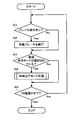
- FIG. 2 is an example of a flowchart showing details of processing executed by the traveling control device 20.
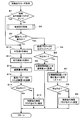
- FIG. 3 is an example of a flowchart showing details of a control travel mode process executed by the travel control apparatus 20 according to the first embodiment.
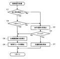
- FIG. 4 is an example of a flowchart showing details of the control travel process.
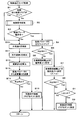
- FIG. 5 is an example of a flowchart showing details of the control travel mode process executed by the travel control apparatus 20 according to the second embodiment.
- the travel control system 1 is a system that is mounted on the vehicle 100 and automatically controls acceleration / deceleration of the vehicle 100.
- FIG. 1 is a block diagram showing the configuration of the traveling control system 1.
- a brake operation device 10 a radar device 11, a vehicle speed sensor 12, an outside air temperature sensor 13, a mode change switch 14, a travel control device 20, a brake device 30, and an accelerator throttle 40 are provided.
- the brake operation device 10 is an input device that is operated by a driver of the vehicle 100 in order to brake the vehicle 100.
- the brake operation device 10 includes a brake pedal and a stroke simulator (not shown).
- the brake pedal is a pedal that receives a stepping operation from a driver.
- the stroke simulator is a device that detects the amount F of depression of the brake pedal by the driver. When the stroke simulator detects a depression operation of the brake pedal by the driver, the stroke simulator transmits data indicating the depression amount F to the travel control device 20.
- the radar device 11 is a device that detects a preceding vehicle traveling in front of the vehicle 100. For example, the radar device 11 irradiates an electromagnetic wave forward of the vehicle 100 and detects a preceding vehicle based on information such as the phase and frequency of the reflected wave of the electromagnetic wave. When the radar device 11 detects a preceding vehicle, the radar device 11 calculates information regarding the position and movement of the preceding vehicle. Specifically, the radar device 11 detects an inter-vehicle distance L (km) from the vehicle 100 to the preceding vehicle as movement information of the preceding vehicle. The radar device 11 transmits data indicating the inter-vehicle distance L to the travel control device 20.
- the radar device 11 may detect the preceding vehicle and calculate the inter-vehicle distance L using any conventionally known method.
- the travel control system 1 is not limited to the radar device 11 and may include other devices that can detect the inter-vehicle distance L from the vehicle 100 to the preceding vehicle.
- the traveling control system 1 may be equipped with an image processing device that captures an image in front of the vehicle 100 and calculates the inter-vehicle distance L based on the image.
- the vehicle speed sensor 12 is a sensor device that detects the traveling speed V of the vehicle 100.
- the vehicle speed sensor 12 transmits data indicating the detected traveling speed V to the traveling control device 20.
- the vehicle speed sensor 12 may calculate the traveling speed V using any conventionally known method.
- the outside air temperature sensor 13 is a sensor device that detects the outside air temperature K around the vehicle 100.
- the outside air temperature sensor 13 transmits data indicating the detected outside air temperature K to the travel control device 20.
- the outside air temperature sensor 13 may detect the outside air temperature K using any conventionally known method.
- the mode switch 14 is a switch device for switching the mode of processing executed by the travel control device 20.
- the mode change switch 14 is typically a push-type latch switch.
- the mode changeover switch 14 is arranged at a position where the driver can operate in the passenger compartment of the vehicle 100.
- the mode change switch 14 receives an input operation from the user, the mode change switch 14 outputs a switch input signal indicating that the input has been made to the travel control device 20.
- the travel control device 20 switches the control mode to either the control travel mode or the normal travel mode every time a switch input signal is received.
- the controlled travel mode is a mode for executing a controlled travel mode process shown in FIG.
- the normal travel mode is a mode in which the control travel mode process is not executed.
- the travel control device 20 is typically an ECU (Electronic Control Unit) mounted on the vehicle 100.
- the travel control device 20 includes an information processing device such as a CPU (Central Processing Unit), a storage device such as a memory, an interface circuit, and the like.
- the travel control device 20 controls the operation of the brake device 30 and the accelerator throttle 40 based on the data received from the above devices and sensors. Details of the processing executed by the travel control device 20 will be described later.
- the brake device 30 is a device that generates a braking force on the vehicle 100.
- the brake device 30 automatically generates a hydraulic fluid pressure according to a control process of the traveling control device 20 and a first hydraulic fluid source 32 that manually generates a hydraulic fluid pressure according to a driver's operation.
- a second hydraulic fluid pressure source 33 a first hydraulic fluid pressure source 32 includes a master cylinder unit 321 and a first electromagnetic valve 322.
- the second hydraulic fluid pressure source 33 includes a motor pump 331, an accumulator 332, and a second electromagnetic valve 333.
- the brake device 30 includes a reservoir 31 and a wheel cylinder 34.
- the reservoir 31 is a storage tank that stores hydraulic fluid.
- the hydraulic fluid stored in the reservoir 31 may be any liquid that is generally used as brake fluid, such as polyethylene glycol.
- the master cylinder unit 321 is a device that is connected to the reservoir 31 and pressurizes and accumulates the hydraulic fluid stored in the reservoir 31 according to the depression amount F.
- the hydraulic fluid accumulated in the master cylinder unit 321 flows into the wheel cylinder 34 when the first electromagnetic valve is opened.
- the first solenoid valve is a solenoid valve whose open / close state is switched according to an instruction signal from the travel control device 20.
- the traveling control device 20 outputs an instruction signal for switching the open / close state of the first solenoid valve when the driver's input operation is received in the brake operation device 10.
- the hydraulic fluid accumulated in the master cylinder unit 321 flows into the wheel cylinder 34 when the first electromagnetic valve is opened.
- the motor pump 331 is a device that is connected to the reservoir 31 and automatically pressurizes the hydraulic fluid stored in the reservoir 31 in accordance with a deceleration instruction signal from the travel control device 20 and accumulates it in the accumulator 332.
- the second electromagnetic valve is an electromagnetic valve whose open / close state is switched in accordance with an instruction from the travel control device 20.
- the second solenoid valve is kept closed in a normal state, and is opened when a deceleration instruction signal is received.
- the hydraulic fluid accumulated in the accumulator 332 flows into the wheel cylinder 34 when the second electromagnetic valve is opened.
- the wheel cylinder 34 is a device that generates a braking force for the vehicle 100 in accordance with the hydraulic pressure of the hydraulic fluid that has flowed from the master cylinder unit 321 and the accumulator 332.
- the wheel cylinder 34 is attached to a wheel provided in the vehicle 100. Then, the wheel cylinder 34 generates braking force on the vehicle 100 by suppressing the rotation of each wheel of the vehicle 100 according to the hydraulic pressure of the hydraulic fluid that has flowed in.
- the automatic generation of a braking force on the vehicle 100 by the hydraulic pressure generated by the motor pump 331 is referred to as a control brake.
- the accelerator throttle 40 is a device that controls the magnitude of the driving force of the vehicle 100.
- the accelerator throttle 40 increases the driving force of the vehicle 100 by increasing the number of revolutions of the engine of the vehicle 100 according to the instruction signal received from the travel control device 20.
- the accelerator throttle 40 may increase the driving force generated by the device such as the electric motor. .
- FIG. 2 is an example of a flowchart showing details of processing executed by the travel control device 20 according to the first embodiment.
- the travel control device 20 executes the process of the flowchart of FIG.
- the traveling control device 20 first executes the processing of step A1.
- step A1 the traveling control device 20 determines whether or not a brake operation has been performed. Specifically, the traveling control device 20 determines whether data indicating the depression amount F has been received from the brake operation device. When the travel control device 20 receives data indicating the depression amount F from the brake operation device, the travel control device 20 determines that the brake operation has been performed, and advances the processing to step A2. On the other hand, if the traveling control device 20 has not received the data indicating the depression amount F from the brake operation device, it determines that there is no brake operation and advances the processing to step A3.
- step A2 the traveling control device 20 executes manual braking. Specifically, the traveling control device 20 outputs an instruction signal that instructs the master cylinder unit 321 to generate the hydraulic fluid pressure corresponding to the depression amount F. Then, the traveling control device 20 outputs an instruction signal for opening the first electromagnetic valve. By the processing in step A2, a braking force is generated in the vehicle 100 in accordance with the driver's operation. When the process of step A2 is completed, the traveling control device 20 advances the process to step A3.
- step A3 the traveling control device 20 determines whether or not the controlled traveling mode is selected. Specifically, the traveling control device 20 confirms its own control mode switched according to an input signal from the mode change switch 14. When it is determined that the control travel mode is selected, the travel control device 20 advances the process to step A4 and executes the control travel mode process. On the other hand, when it is determined that the normal travel mode is selected, the travel control device 20 advances the process to step A5 without executing the control travel mode process.
- step A4 the traveling control device 20 executes a controlled traveling mode process.
- the details of the control travel mode process will be described with reference to FIG.
- FIG. 3 is an example of a flowchart showing details of the control travel mode process executed by the travel control apparatus 20 according to the first embodiment.
- the traveling control apparatus 20 first executes the process of step B1.
- step B1 the traveling control device 20 determines whether or not the controlled traveling restriction flag is on.
- the control travel restriction flag is flag data indicating that it is necessary to restrict the execution of the control travel processing of the vehicle 100 by the travel control device 20 when the flag is set to ON.
- the on / off state of the control travel restriction flag is stored in the storage device of the travel control device 20. Further, the on / off state of the control travel restriction flag is switched by processing from step B3 to step B15 described later executed by the travel control device 20.
- the travel control device 20 advances the process to step B2 and executes the control travel process.
- travel control device 20 advances the process to step B10 without executing the control travel process.
- step B2 the traveling control device 20 executes a controlled traveling process.
- the controlled travel process is a process for executing a follow-up travel that automatically follows the preceding vehicle or a constant speed travel that causes the vehicle 100 to travel at a constant speed.
- FIG. 4 is an example of a flowchart showing details of the control traveling process.
- step C1 the traveling control device 20 determines whether or not a preceding vehicle has been detected. Specifically, the traveling control device 20 determines whether data indicating the inter-vehicle distance L is received from the radar device 11. When the data indicating the inter-vehicle distance L is received from the radar device 11, the traveling control device 20 determines that a preceding vehicle has been detected, and advances the processing to step C ⁇ b> 2. On the other hand, when the data indicating the inter-vehicle distance L is not received from the radar device 11, the traveling control device 20 determines that the preceding vehicle has not been detected, and the process proceeds to step C3.
- step C2 the traveling control device 20 determines whether or not the inter-vehicle distance L is equal to or less than the target distance Lt1.
- traveling control device 20 determines that inter-vehicle distance L is equal to or smaller than target distance Lt1
- the process proceeds to step C5.
- traveling control device 20 determines that inter-vehicle distance L is greater than target distance Lt1
- the process proceeds to step C3.
- step C3 the traveling control device 20 detects the traveling speed V. Specifically, the traveling control device 20 receives data indicating the traveling speed V from the vehicle speed sensor 12, and stores the data in the storage device. When the traveling control device 20 completes the process of step C3, the traveling control apparatus 20 advances the process to step C4.
- step C4 the traveling control device 20 determines whether or not the traveling speed V is less than the target speed Vt.
- the target speed Vt is a value indicating the target traveling speed of the vehicle 100 when the traveling control device 20 controls the vehicle 100 to travel at a constant speed.
- the target speed Vt is an arbitrary constant stored in advance in the storage device of the traveling control device 20. Note that the value of the target speed Vt may be arbitrarily designated by the driver of the vehicle 100. If the traveling control device 20 determines that the traveling speed V is less than the target speed Vt, the traveling control device 20 advances the process to step C7. On the other hand, when the traveling control device 20 determines that the traveling speed V is equal to or higher than the target speed Vt, the traveling control apparatus 20 advances the process to step C5.
- step C5 the traveling control device 20 calculates a target deceleration Gt.
- the target deceleration Gt is a deceleration necessary for making the inter-vehicle distance L coincide with the target distance Lt1, or a deceleration of the vehicle 100 necessary for making the traveling speed V coincide with the target speed Vt.
- the traveling control device 20 calculates a deceleration necessary for making the inter-vehicle distance L coincide with the target distance Lt1 as the target deceleration Gt.
- the traveling control device 20 calculates the deceleration of the vehicle 100 necessary for making the traveling speed V coincide with the target speed Vt as the target deceleration Gt.
- the traveling control device 20 may calculate the target deceleration Gt using any conventionally known method.
- step C6 the traveling control device 20 starts a control brake. Specifically, first, the traveling control device 20 calculates the magnitude of the hydraulic fluid pressure LP to be generated by the motor pump 331 according to the target deceleration Gt. Then, the traveling control device 20 outputs data indicating the hydraulic fluid pressure LP together with the deceleration instruction signal to the motor pump 331. Moreover, the traveling control apparatus 20 outputs a deceleration instruction signal to the second electromagnetic valve 333, and opens the second electromagnetic valve 333. By the process of step C6, a braking force corresponding to the hydraulic fluid pressure generated by the motor pump 331 is automatically applied to the vehicle 100. When the traveling control device 20 completes the process of step C6, the traveling control apparatus 20 completes the controlled traveling process and advances the process to step B3 of the flowchart of FIG.
- step C7 the traveling control device 20 starts acceleration control. Specifically, traveling control device 20 outputs an instruction signal for increasing the driving force of vehicle 100 to accelerator throttle 40. By the processing, the vehicle 100 is accelerated and the traveling speed V is increased.
- the traveling control device 20 completes the process of step C7, the traveling control device 20 completes the controlled traveling process and advances the process to step B3 in the flowchart of FIG.
- the vehicle 100 when there is a preceding vehicle in front of the vehicle 100, the vehicle 100 precedes the vehicle 100 so that the vehicle 100 follows the vehicle 100 while maintaining the target inter-vehicle distance Lt1.
- the acceleration / deceleration state of the vehicle 100 is automatically controlled so that the vehicle 100 travels at the target travel speed Vt.
- the traveling control device 20 may automatically control the braking force of the vehicle 100 by operating the motor pump 331 at an arbitrary timing.
- step B3 the traveling control device 20 determines whether or not the control brake is operating. Specifically, the traveling control device 20 executes the process of step C6 in the above-described controlled traveling process, and determines whether or not a deceleration instruction signal has been output. When traveling control device 20 outputs a deceleration instruction signal and determines that the control brake is operating, the process proceeds to step B4. On the other hand, when the traveling control device 20 has not output the deceleration instruction signal and determines that the control brake is not operating, the traveling control device 20 advances the process to step B10.
- step B4 the traveling control device 20 counts up the load parameter R.
- the load parameter R is a numerical value indicating the operation load of the motor pump 331 accumulated by the operation of the motor pump 331.
- the traveling control device 20 adds the value of the target deceleration Gt calculated in step C5 to the load parameter R, and overwrites and stores the value after addition as a new load parameter R value in the storage device. To do. It should be noted that the initial value of the load parameter R may be any predetermined numerical value.
- step B3 and step B4 The processing of step B3 and step B4 is repeatedly executed, whereby the integrated value of the target deceleration Gt while the control brake is operating is calculated as the load parameter R.
- the operation load of the motor pump 331 can be estimated and calculated by a simple process by integrating the target deceleration Gt. is there. Further, according to the above processing, the value of the load parameter R continues to increase while the control brake is operating. That is, the load parameter R can be calculated according to the continuous operation time of the motor pump 331.
- step B5 the traveling control device 20 determines whether or not the load parameter R is equal to or greater than the inter-vehicle distance change threshold value Rt1.
- the inter-vehicle distance change threshold value Rt1 is a threshold value for determining whether or not the target inter-vehicle distance Lt1 is changed according to the value of the load parameter R.
- the inter-vehicle distance change threshold value Rt1 is an arbitrary constant stored in advance in the storage device of the travel control device 20.
- the traveling control device 20 advances the process to step B7.
- the traveling control device 20 advances the process to step B6.
- step B6 the traveling control device 20 sets the target inter-vehicle distance Lt1 to the normal value ⁇ .
- the normal value ⁇ is a constant stored in advance in the storage device of the travel control device 20.
- the value of the normal value ⁇ may be arbitrarily set by the driver of the vehicle 100.
- step B7 the traveling control device 20 sets the target inter-vehicle distance Lt1 to the correction value ⁇ .
- the correction value ⁇ is an arbitrary constant larger than the normal value ⁇ stored in advance in the storage device of the travel control device 20.
- the traveling control device 20 calculates in advance as a correction value ⁇ a value obtained by adding a predetermined constant to the normal value ⁇ . The above setting may be made later.
- the traveling control apparatus 20 advances the process to step B8.
- step B8 the traveling control device 20 determines whether or not the load parameter R is equal to or greater than the control limit threshold Rt2.
- the control limit threshold value Rt2 is a threshold value for determining whether or not to set the state of the control travel limit flag to ON according to the magnitude of the load parameter R.
- the control limit threshold Rt2 is an arbitrary constant larger than the inter-vehicle distance change threshold Rt1.
- the control limit threshold value Rt2 is stored in advance in the storage device of the travel control device 20. If the travel control device 20 determines that the load parameter R is equal to or greater than the control limit threshold value Rt2, the travel control device 20 advances the process to step B9. On the other hand, when it is determined that the load parameter R is less than the control limit threshold value Rt2, the traveling control device 20 completes the controlled traveling mode process and advances the process to step A5 in FIG.
- step B9 the traveling control device 20 sets the control traveling restriction flag to ON.
- the traveling control device 20 completes the process of step B9, the traveling control mode process is completed, and the process proceeds to step A5 of FIG.
- step B5 to step B9 when the load parameter R is equal to or greater than the control limit threshold Rt2, that is, when the operating load of the motor pump 331 is relatively high, execution of the control travel processing is prohibited. Is done. By such processing, the continuous operation of the motor pump 331 can be restricted, and the motor pump 331 can be prevented from being damaged.
- the target inter-vehicle distance Lt1 is corrected in advance to a larger value than usual when the load parameter R becomes equal to or greater than the inter-vehicle distance change threshold value Rt1, before the control traveling process is stopped, the vehicle 100 and the preceding vehicle The inter-vehicle distance can be increased in advance. Therefore, before the operation of the automatic brake device 30 is restricted, the risk that the own vehicle 100 collides with the preceding vehicle can be reduced in advance.
- step B10 the traveling control device 20 detects the outside air temperature K. Specifically, the traveling control device 20 receives data indicating the outside air temperature K from the outside air temperature sensor 13. When the traveling control device 20 completes the process of step B10, the process proceeds to step B11.
- step B11 the traveling control device 20 detects the traveling speed V. Specifically, the traveling control device 20 receives data indicating the traveling speed V from the vehicle speed sensor 12. When the traveling control device 20 completes the process of step B11, the traveling control apparatus 20 advances the process to step B12.
- step B12 the traveling control device 20 calculates a subtraction value Q.
- the subtraction value Q is a numerical value that is repeatedly subtracted from the load parameter R while the control brake is not executed, that is, while the motor pump 331 is not operating.
- the traveling control device 20 calculates the subtraction value Q as a larger value as the outside air temperature K is lower.
- the traveling control device 20 calculates the subtraction value Q as a larger value as the traveling speed V increases.
- step B13 the traveling control device 20 subtracts the subtraction value Q from the motor load R. Specifically, the traveling control device 20 overwrites and stores the value after subtracting the subtraction value Q from the motor load R as a new value of the motor load R in the storage device.
- step B14 the traveling control device 20 completes the process of step B13, the process proceeds to step B14.
- step B14 the traveling control device 20 determines whether or not the load parameter R is equal to or greater than the release threshold value Rt3.
- the release threshold value Rt3 is a threshold value for determining whether or not to set the state of the control travel restriction flag to OFF.
- the control limit threshold Rt2 may be an arbitrary constant, but is preferably a value smaller than the inter-vehicle distance change threshold Rt1.
- the control limit threshold value Rt2 is stored in advance in the storage device of the travel control device 20. If the travel control device 20 determines that the load parameter R is equal to or greater than the release threshold Rt3, the travel control device 20 advances the process to step B15. On the other hand, when it is determined that the load parameter R is less than the release threshold value Rt3, the traveling control device 20 completes the controlled traveling mode process and advances the process to step A5 in FIG.
- step B15 the traveling control device 20 sets the control traveling restriction flag to OFF.
- the traveling control device 20 completes the process of step B15, the traveling control mode process is completed, and the process proceeds to step A5 in FIG.
- the value of the load parameter R is gradually reduced by repeatedly executing the processing from step B10 to step B13. Since the motor pump 331 is gradually cooled while the control brake is not executed, it is considered that the operating load accumulated in the motor pump 331 is gradually reduced. Therefore, according to the processing from step B10 to step B15, the value of the load parameter R can be maintained at an appropriate value according to the downtime of the motor pump 331.
- the control travel restriction flag can be set to the off state. That is, when it is determined that the motor pump 331 has been sufficiently cooled, the restriction of the control traveling process can be released and the process can be resumed.
- the traveling control device 20 increases or decreases the subtraction value Q according to the traveling speed V so that the value of the load parameter R is more appropriate. Can be reduced to Similarly, since the motor pump 331 is cooled earlier as the outside air temperature K is larger, the traveling control device 20 increases or decreases the value of the load parameter R by increasing or decreasing the subtraction value Q according to the magnitude of the outside air temperature K. Can be reduced appropriately.
- the value of the subtraction value Q may be set in advance as an arbitrary fixed value.
- the calculation amount of the travel control device 20 can be reduced compared to the above processing.
- step A5 the traveling control device 20 determines whether or not the IG power source is set to OFF. If the traveling control device 20 determines that the IG power source is set to OFF, the traveling control device 20 ends the process of FIG. On the other hand, when it is determined that the IG power source is not set to OFF, traveling control device 20 returns the process to step A1 and repeatedly executes the above-described process.
- the operation load of the device for operating the control brake such as the motor pump 331 becomes relatively high.
- the device can be deactivated. Therefore, breakage of the device can be prevented, and traveling control of the vehicle 100 can be stably executed.
- the traveling control system 1 since the controlled traveling process is stopped when the load of the motor pump 331 becomes high as described above, the motor pump 331 can be prevented from being damaged. Can do.
- FIG. 5 is an example of a flowchart illustrating details of the control travel mode process executed by the travel control apparatus 20 according to the second embodiment.
- steps in which the traveling control device 20 executes the same process as the process of FIG. 3 described in the first embodiment are denoted by the same reference numerals, and detailed description thereof is omitted.
- the travel control device 20 according to the second embodiment executes the process of step D1 shown below. To do.
- Step D1 the traveling control device 20 determines whether or not the inter-vehicle distance L is equal to or greater than the distance threshold Lt2.
- the distance threshold Lt2 is an arbitrary constant value stored in the storage device of the travel control device 20.
- the distance threshold Lt2 may be an arbitrary value, but is more preferably the same value as the correction value ⁇ described above.
- the traveling control device 20 advances the process to step B9 described above.
- the traveling control device 20 returns the process to step A1 in FIG.
- the control travel limit flag is turned on. Set to state. That is, the control travel process can be stopped only when the inter-vehicle distance between the vehicle 100 and the preceding vehicle is surely ensured by the distance threshold Lt2. Therefore, when the control traveling process is stopped, the risk of a collision between the vehicle 100 and the preceding vehicle can be more reliably reduced.
- the travel control device 20 uses other methods to load parameter R R may be calculated.
- the traveling control device 20 adds the rotation speed rev to the load parameter R instead of the target deceleration Gt, and uses the value after the addition as a new load parameter R value. May be overwritten in the storage device. According to such processing, the integrated value of the rotational speed rev while the control brake is operating is calculated as the load parameter R. Since the operating load of the motor pump 331 surely increases as the rotational speed rev increases, the travel control device 20 can accurately calculate the operating load of the motor pump 331 according to the above processing.
- the traveling control system 1 further includes a hydraulic pressure sensor that detects the hydraulic pressure bp actually generated by the motor pump 331.
- the traveling control device 20 adds the hydraulic pressure value bp to the load parameter R instead of the target deceleration Gt, and sets the added value as a new load parameter R.
- the value may be overwritten and stored in the storage device.
- the integrated value of the hydraulic pressure value bp calculated while the control brake is operating is calculated as the load parameter R. Since the operating load of the motor pump 331 increases reliably as the operating hydraulic pressure value bp increases, the travel control device 20 can accurately calculate the operating load of the motor pump 331 according to the above processing.
- the travel control device 20 may perform the process of suppressing the operation amount of the control brake instead of stopping the execution of the control travel process as described above. good.
- the travel control device 20 executes processing such as limiting the target deceleration Gt calculated in step C5 to a predetermined constant or less. It doesn't matter.
- the configuration of the brake device 30 shown in each of the above embodiments is merely an example, and any brake device may be replaced with the brake device 30 as long as it is a device that automatically generates a braking force regardless of the operation of the driver. Can be used.
- the traveling control system and the traveling control device according to the present invention are useful as a traveling control system and a traveling control device that can prevent the breakage and abnormal operation of the brake device and can operate stably.
Landscapes
- Engineering & Computer Science (AREA)
- Transportation (AREA)
- Mechanical Engineering (AREA)
- Chemical & Material Sciences (AREA)
- Combustion & Propulsion (AREA)
- Automation & Control Theory (AREA)
- Human Computer Interaction (AREA)
- Control Of Driving Devices And Active Controlling Of Vehicle (AREA)
- Regulating Braking Force (AREA)
Abstract
ブレーキデバイスの破損や異常動作を防止し、安定した動作が可能な走行制御システムおよび走行制御装置を提供する。 車両に搭載され、当該車両の制動力を自動的に制御する走行制御システムであって、入力された作動液圧に応じて車両に制動力を発生させるブレーキ手段と、作動液圧を車両の運転者の操作に関わらず自動的に発生させる自動液圧発生手段と、自動液圧発生手段の作動により蓄積された当該自動液圧発生手段の作動負荷を示す負荷パラメータの値を算出する負荷算出手段と、負荷パラメータの値が予め定められた制御制限閾値以上となった場合、自動液圧発生手段の動作を制限する制御制限手段とを備えることを特徴とする、走行制御システム。
Description
本発明は、走行制御システムおよび走行制御装置に関し、より特定的には、車両の制動力を自動的に制御する走行制御システムおよび走行制御装置に関する。
一般的に、液圧式の車両のブレーキ装置は、作動液を蓄圧し、当該蓄圧された作動液をホイールシリンダへ流入させることによって車両に制動力を発生させる。このようなブレーキ装置において、モーターポンプ等のデバイスを駆動することによって作動液の蓄圧状態を自動制御する電子制御式のブレーキ装置が開発されている(例えば、特許文献1参照)。
上記のような電子制御式のブレーキ装置を応用し、ドライバーの操作に関わらず車両に自動的に制動力を発生させるブレーキ装置が開発されている。このようなブレーキ装置は、先行車と自車両との車間距離を一定に保つよう自車両の加減速状態を自動制御する走行制御システムを備えた車両などに備えられている。一般的に、このような走行制御システムと併用されるブレーキ装置は、ドライバーの操作に応じて作動液圧を増減する第1の作動液入力系統と、ドライバーの操作に関わらず第1の液圧入力系統と独立して自動的に作動液圧を増減する第2の作動液入力系統と、各系統からの作動液の入力に応じて制動力を発生させるホイールシリンダを備える構成となっている。上記走行制御システムを制御する制御装置は、車両を減速する必要があると判断した場合、モーターポンプ等を電子制御で駆動することによって第2の液圧入力系統において作動液を蓄圧する。そして、制御装置は、第2の液圧入力系統において蓄圧された作動液をホイールシリンダへ流入させることによって車両に自動的に制動力を発生させる。すなわち、上記のような走行制御システムにおいては、自動的な制動力の発生(所謂、制御ブレーキ)が実行される度に、作動液を蓄圧するべくモーターポンプ等のデバイスが動作する。
しかしながら、上記のような走行制御システムにおいて制御ブレーキが頻繁且つ継続的に実行された場合、作動液を蓄圧するモーターポンプ等のデバイスの作動負荷が高くなってしまう。そして、モーターポンプ等のデバイスの作動負荷が極端に高くなると、当該デバイスが故障したり異常動作したりする虞があった。すなわち、従来の走行制御システムでは、安定して車両の走行制御を実行できなくなる可能性があった。
本発明は上記の課題を鑑みて成されたものであり、ブレーキデバイスの破損や異常動作を防止し、安定した動作が可能な走行制御システムおよび走行制御装置を提供することを目的とする。
上記の課題を解決するため、本発明は以下の構成を採用した。すなわち、本発明の第1の局面は、車両に搭載され、当該車両の制動力を自動的に制御する走行制御システムであって、入力された作動液圧に応じて車両に制動力を発生させるブレーキ手段と、作動液圧を車両の運転者の操作に関わらず自動的に発生させる自動液圧発生手段と、自動液圧発生手段の作動により蓄積された当該自動液圧発生手段の作動負荷を示す負荷パラメータの値を算出する負荷算出手段と、負荷パラメータの値が予め定められた制御制限閾値以上となった場合、自動液圧発生手段の動作を制限する制御制限手段とを備えることを特徴とする、走行制御システムである。
第2の局面は、第1の局面において、車両の前方を走行する先行車を検出する先行車検出手段と、車両が先行車に対して目標車間距離を隔てて追従走行するよう当該車両を減速させる減速指示信号を自動液圧発生手段へ適宜出力する制御走行指示手段とをさらに備え、自動液圧発生手段は、受信した減速指示信号に応じて作動液圧を自動的に発生させ、制御制限手段は、負荷パラメータが予め定められた制御制限閾値以上となった場合、制御走行指示手段による減速指示信号の出力を禁止することによって、自動液圧発生手段の動作を停止させることを特徴とする。
第3の局面は、第2の局面において、負荷パラメータが予め定められた車間距離変更閾値以上、且つ制御制限閾値未満である場合、目標車間距離の値を負荷パラメータが車間距離変更閾値未満である場合に比べて大きな値に変更する、目標車間距離変更手段をさらに備えることを特徴とする。
第4の局面は、第1乃至3の何れか1つの局面において、負荷算出手段は、自動液圧発生手段が継続して作動している時間が長いほど負荷パラメータを大きな値に算出することを特徴とする。
第5の局面は、第4の局面において、車両の目標減速度を算出する目標減速度算出手段と、車両の減速度を検出する減速度検出手段とをさらに備え、制御走行指示手段は、減速度が目標減速度となるよう減速指示信号を出力して車両を減速させ、負荷算出手段は、自動液圧発生手段が作動している間における目標減速度の積算値を負荷パラメータとして算出することを特徴とする。
第6の局面は、第4の局面において、自動液圧発生手段は、モーターポンプを回転駆動することにより作動液圧を発生させ、負荷算出手段は、自動液圧発生手段が作動している間におけるモーターポンプの回転数の積算値を負荷パラメータとして算出することを特徴とする。
第7の局面は、第4の局面において、自動液圧発生手段により発生された作動液圧の液圧値を検出する液圧値検出手段をさらに備え、負荷算出手段は、自動液圧発生手段が作動している間における液圧値の積算値を負荷パラメータとして算出することを特徴とする。
第8の局面は、第1乃至7の何れか1つの局面において、制御制限手段は、自動液圧発生手段が作動していない間、負荷パラメータから減算値を繰り返し減算し、負荷パラメータが予め定められた解除閾値以下となった場合、自動液圧発生手段の動作の制限を解除することを特徴とする。
第9の局面は、第8の局面において、車両周囲の気温を検出する外気温検出手段と、気温が低いほど減算値を大きな値に設定する減算値設定手段とをさらに備えることを特徴とする。
第10の局面は、第8および9の何れか1つの局面において、車両の走行速度を検出する自車速度検出手段と、車両の走行速度が速いほど減算値を大きな値に設定する減算値設定手段とをさらに備えることを特徴とする。
第11の局面は、第2の局面において、車両と先行車との車間距離が予め定められた距離閾値以上であるか否かを判定する車間距離判定手段と、制御制限手段は、負荷パラメータが予め定められた制御制限閾値以上となり、且つ車間距離が距離閾値以上である場合に、自動液圧発生手段の動作を制限することを特徴とする。
第12の局面は、第2の局面において、制御走行指示手段は、車両が先行車と目標車間距離を維持して追従走行するよう、減速指示信号および車両を加速させる加速指示信号を適宜出力し、走行制御システムは、加速指示信号に応じて車両の駆動力を自動的に増加させる駆動力制御手段をさらに備え、制御制限手段は、負荷パラメータが予め定められた制御制限閾値以上となった場合、制御走行指示手段による減速指示信号および加速指示信号の出力を禁止することを特徴とする。
第13の局面は、車両に搭載され、当該車両の制動力を自動的に制御する走行制御装置であって、車両は、入力された作動液圧に応じて車両に制動力を発生させるブレーキ手段と、作動液圧を車両の運転者の操作に関わらず自動的に発生させる自動液圧発生手段とを備え、走行制御装置は、自動液圧発生手段の作動により蓄積された当該自動液圧発生手段の作動負荷を示す負荷パラメータの値を算出する負荷算出手段と、負荷パラメータの値が予め定められた制御制限閾値以上となった場合、自動液圧発生手段の動作を制限する制御制限手段とを備えることを特徴とする、走行制御装置である。
第1の局面によれば、自動的に制動力を発生させるためのデバイス(特許請求の範囲における自動液圧発生手段)の負荷が比較的高くなった場合に、当該デバイスの作動を停止させることができる。したがって上記デバイスの破損を防止し、安定して動作する走行制御システムを得ることができる。
第2の局面によれば、先行車に対して所定の車間距離を隔てて車両を追従させる走行制御を行う走行制御システムにおいて、自動的に制動力を発生させるためのデバイスの破損を防止することができる。すなわち、自動的に制動力を発生させるためのデバイスが継続的に作動する頻度が比較的高くなる走行制御が実行されている状況下において、当該デバイスの破損を防止することができる。
第3の局面によれば、車両を自動的に減速させる減速制御を禁止する前に、予め自車両と先行車との車間距離を比較的長く隔てておくことができる。減速制御の禁止を開始した後は、自車両と先行車とが急接近したとしても自動的に制動力が発生する(制御ブレーキが動作する)ことが無いため、自車両と先行車とが衝突する危険性が高くなる可能性がある。第3の局面はこのような状況を想定して成されたものであり、上記の通り予め自車両と先行車との車間距離を比較的長く隔ておくことによって、自車両と先行車との衝突の危険性を低減することができる。
第4の局面によれば、作動液を蓄圧するデバイスの作動負荷の大きさを簡単な処理で算出することができる。
第5の局面によれば、自動液圧発生手段の作動負荷の大きさを目標減速度に基づいて容易に推定することができる。目標減速度の大きさに伴い自動液圧発生手段の作動負荷は大きくなると考えられる。したがって、目標減速度を積算することによって自動液圧発生手段の作動負荷を容易に推定することができるのである。
第6の局面によれば、自動液圧発生手段の作動負荷の大きさを当該自動液圧発生手段に含まれるモーターポンプの回転数に基づいて容易且つ正確に推定することができる。モーターポンプの回転数が大きいほど当該モーターポンプの負荷が高い状態であると言える。したがって、モーターポンプの回転数を積算することによって自動液圧発生手段の作動負荷を容易且つ正確に推定することができるのである。
第7の局面によれば、自動液圧発生手段の作動負荷の大きさを当該自動液圧発生手段が発生させる作動液圧に基づいて容易且つ正確に推定することができる。
第8の局面によれば、自動制御が制限された後、自動液圧発生手段の作動負荷が比較的低下した状態であるか否かを簡単な処理で判定することができる。また、自動液圧発生手段の作動負荷が比較的低下した状態であると判定された場合、自動的な減速処理の制限を解除することができる。
第9の局面によれば、外気温が比較的低い状況下、すなわち自動液圧発生手段に含まれるモーターポンプ等のデバイスの温度が下がり易い状況下においては、比較的早期に自動的な減速処理を再開することができる。
第10の局面によれば、車両の走行速度が比較的速い場合、すなわち自動液圧発生手段に含まれるモーターポンプ等のデバイスの温度が下がり易い状況である場合、比較的早期に自動的な減速処理の制限を解除することができる。
第11の局面によれば、車両と先行車との車間距離が確実に確実に距離閾値以上乖離した場合にのみ自動的な制動力の発生を制限することができる。したがって、自動的な制動力の発生を制限した際に、車両100と先行車とが衝突する危険性を、より確実に低減することができる。
第12の局面によれば、自動的な減速制御が禁止されている際に、自動的な加速制御の実行も禁止することができる。したがって、例えば、車両が先行車と所定の車間距離を隔てて自動追従走行するよう当該車両の加速および減速が制御されている場合において、自動的な加速制御のみが実行されて車両が先行車に衝突する危険性を低減することができる。
第13の局面によれば、上述第1の局面と同様の効果を奏することができる。
(第1の実施形態)
以下、本発明の第1の実施形態に係る走行制御システム1について説明する。走行制御システム1は、車両100に搭載され、当該車両100の加減速を自動的に制御するシステムである。
以下、本発明の第1の実施形態に係る走行制御システム1について説明する。走行制御システム1は、車両100に搭載され、当該車両100の加減速を自動的に制御するシステムである。
先ず、図1を参照して走行制御システム1の構成について説明する。なお、図1は走行制御システム1の構成を示すブロック図である。図1に示すように、ブレーキ操作装置10、レーダー装置11、車速センサ12、外気温センサ13、モード切替スイッチ14、走行制御装置20、ブレーキ装置30、およびアクセルスロットル40を備える。
ブレーキ操作装置10は、車両100のドライバーが当該車両100にブレーキをかけるために操作する入力装置である。ブレーキ操作装置10は、ブレーキペダルおよびストロークシミュレータから構成される(図示せず)。ブレーキペダルは、ドライバーからの踏み込み操作を受け付けるペダルである。ストロークシミュレータは、ドライバーがブレーキペダルを踏み込み量Fを検出するデバイスである。ストロークシミュレータは、ドライバーによるブレーキペダルの踏み込み操作を検出すると、踏み込み量Fを示すデータを走行制御装置20へ送信する。
レーダー装置11は、車両100の前方を走行する先行車を検出する装置である。レーダー装置11は、例えば、車両100の前方へ電磁波を照射し、当該電磁波の反射波の位相や周波数等の情報に基づいて先行車を検出する。レーダー装置11は、先行車を検出した場合、当該先行車の位置や移動に関する情報を算出する。具体的には、レーダー装置11は、先行車の移動情報として、車両100から先行車までの車間距離L(km)を検出する。そして、レーダー装置11は、車間距離Lを示すデータを走行制御装置20へ送信する。なお、レーダー装置11は、従来周知の任意の手法を用いて先行車の検出、および車間距離Lの算出を行って良い。また、走行制御システム1は、レーダー装置11に限らず、車両100から先行車まで車間距離Lを検出可能な他の装置を備えて良い。例えば、走行制御システム1は、車両100の前方の画像を撮像し、当該画像に基づいて車間距離Lを算出する画像処理装置を搭載して構わない。
車速センサ12は、車両100の走行速度Vを検出するセンサ装置である。車速センサ12は、検出した走行速度Vを示すデータを走行制御装置20へ送信する。なお、車速センサ12は、従来周知の任意の手法を用いて走行速度Vを算出して良い。
外気温センサ13は、車両100周囲の外気温Kを検出するセンサ装置である。外気温センサ13は、検出した外気温Kを示すデータを走行制御装置20へ送信する。なお、外気温センサ13は、従来周知の任意の手法を用いて外気温Kを検出して良い。
モード切替スイッチ14は、走行制御装置20が実行する処理のモードを切り替えるためのスイッチ装置である。モード切替スイッチ14は、典型的には、押下式のラッチスイッチである。モード切替スイッチ14は、車両100の車室内においてドライバーが操作可能な位置に配置される。モード切替スイッチ14は、ユーザーからの入力操作を受け付けると、当該入力があったことを示すスイッチ入力信号を走行制御装置20へ出力する。走行制御装置20は、スイッチ入力信号を受け付ける毎に、制御走行モード、または通常走行モードの何れかに制御のモードを切り替える。なお、制御走行モードは、後述図3に示す制御走行モード処理を実行するモードである。また、通常走行モードは、制御走行モード処理を実行しないモードである。
走行制御装置20は、典型的には、車両100に搭載されるECU(Electronic Control Unit)である。走行制御装置20は、CPU(Central Processing Unit)などの情報処理装置、メモリなどの記憶装置、およびインターフェース回路などを備える。走行制御装置20は、ブレーキ装置30およびアクセルスロットル40の動作を上述の各装置およびセンサから受信したデータに基づいて制御する。走行制御装置20が実行する処理の詳細については後述する。
ブレーキ装置30は、車両100に制動力を発生させる装置である。ブレーキ装置30は、ドライバーの操作に応じて手動的に作動液圧を発生する第1系統の作動液圧源32と、走行制御装置20の制御処理に応じて自動的に作動液圧を発生する第2系統の作動液圧源33とを備える。第1系統の作動液圧源32は、マスタシリンダユニット321および第1電磁弁322により構成される。第2系統の作動液圧源33は、モーターポンプ331、アキュムレータ332、および第2電磁弁333により構成される。また、ブレーキ装置30は、リザーバ31、およびホイールシリンダ34を備える。
リザーバ31は、作動液を貯蔵する貯蔵タンクである。リザーバ31に貯蔵される作動液は、例えば、ポリエチレングリコールなどの一般的にブレーキフルードとして用いられる任意の液体であって良い。
マスタシリンダユニット321は、リザーバ31と接続され、リザーバ31に貯蔵されている作動液を踏み込み量Fに応じて加圧および蓄積するデバイスである。マスタシリンダユニット321に蓄圧された作動液は、第1電磁弁が開放されることによってホイールシリンダ34へ流入される。第1電磁弁は、走行制御装置20からの指示信号に応じて開閉状態が切り替えられる電磁弁である。なお、走行制御装置20は、ブレーキ操作装置10においてドライバーの入力操作を受け付けた場合に第1電磁弁の開閉状態を切り替える指示信号を出力する。マスタシリンダユニット321内で蓄圧された作動液は、第1電磁弁が開状態とされることによってホイールシリンダ34内へ流入される。
モーターポンプ331は、リザーバ31と接続され、リザーバ31に貯蔵されている作動液を走行制御装置20からの減速指示信号に応じて自動的に加圧し、アキュムレータ332に蓄積するデバイスである。第2電磁弁は、走行制御装置20からの指示に応じて開閉状態が切り替えられる電磁弁である。第2電磁弁は、通常時においては閉状態に維持され、減速指示信号を受信した場合に開状態となる。アキュムレータ332に蓄圧された作動液は、第2電磁弁が開放されることによってホイールシリンダ34へ流入される。
ホイールシリンダ34は、マスタシリンダユニット321、およびアキュムレータ332から流入された作動液の液圧に応じて車両100に対して制動力を発生させる装置である。ホイールシリンダ34は、車両100が備える車輪に取り付けられる。そして、ホイールシリンダ34は、流入された作動液の液圧に応じて車両100の各車輪の回転を抑制することによって、車両100に制動力を発生させる。なお、以下では、モーターポンプ331が発生させた作動液圧によって自動的に車両100に制動力を発生させることを制御ブレーキと呼称する。
アクセルスロットル40は、車両100の駆動力の大きさを制御するデバイスである。アクセルスロットル40は、走行制御装置20から受信する指示信号に応じて車両100のエンジンの回転数を上昇させて車両100の駆動力を増加させる。なお、駆動力を発生させる動力源としてエンジン以外に電気モーター等のデバイスが車両100に搭載されている場合、アクセルスロットル40は、当該電気モーター等のデバイスが発生する駆動力を増加させても良い。
次いで、図2を参照して、走行制御装置20が実行する処理について説明する。図2は、第1の実施形態に係る走行制御装置20が実行する処理の詳細を示すフローチャートの一例である。走行制御装置20は、例えば、車両100のIG電源がオンに設定された場合に、図2のフローチャートの処理を実行する。走行制御装置20は、図2のフローチャートの処理を開始すると、先ず、ステップA1の処理を実行する。
ステップA1において、走行制御装置20は、ブレーキ操作があったか否か判定する。具体的には、走行制御装置20は、ブレーキ操作装置から踏み込み量Fを示すデータを受信したか否か判定する。走行制御装置20は、ブレーキ操作装置から踏み込み量Fを示すデータを受信した場合、ブレーキ操作があったと判定し、処理をステップA2へ進める。一方、走行制御装置20は、ブレーキ操作装置から踏み込み量Fを示すデータを受信していない場合、ブレーキ操作がないと判定し、処理をステップA3へ進める。
ステップA2において、走行制御装置20は、手動ブレーキを実行する。具体的には、走行制御装置20は、踏み込み量Fに応じた作動液圧を発生させるようマスタシリンダユニット321へ指示する指示信号を出力する。そして、走行制御装置20は、第1電磁弁を開状態とする指示信号を出力する。本ステップA2の処理により、ドライバーの操作に応じて車両100に制動力が発生する。ステップA2の処理を完了すると、走行制御装置20は処理をステップA3へ進める。
ステップA3において、走行制御装置20は、制御走行モードが選択されているか否か判定する。具体的には、走行制御装置20は、モード切替スイッチ14からの入力信号に応じて切り替えた自身の制御のモードを確認する。走行制御装置20は、制御走行モードが選択されていると判定した場合、処理をステップA4へ進め、制御走行モード処理を実行する。一方、走行制御装置20は、通常走行モードが選択されていると判定した場合、制御走行モード処理を実行することなく処理をステップA5へ進める。
ステップA4において、走行制御装置20は、制御走行モード処理を実行する。以下、制御走行モード処理の詳細について、図3を参照して説明する。なお、図3は、第1の実施形態に係る走行制御装置20が実行する制御走行モード処理の詳細を示すフローチャートの一例である。走行制御装置20は、制御走行モード処理を開始すると、先ず、ステップB1の処理を実行する。
ステップB1において、走行制御装置20は、制御走行制限フラグがオンか否か判定する。制御走行制限フラグは、当該フラグがオンに設定されている場合に、走行制御装置20による車両100の制御走行処理の実行を制限する必要があることを示すフラグデータである。制御走行制限フラグのオン/オフ状態は、走行制御装置20の記憶装置に記憶される。また、制御走行制限フラグのオン/オフ状態は、走行制御装置20が実行する後述のステップB3からステップB15の処理によって切り替えられる。走行制御装置20は、制御走行制限フラグがオフ状態であると判定した場合、処理をステップB2へ進めて制御走行処理を実行する。一方、走行制御装置20は、制御走行制限フラグがオン状態であると判定した場合、制御走行処理を実行することなく処理をステップB10へ進める。
ステップB2において、走行制御装置20は、制御走行処理を実行する。制御走行処理は、車両100を、自動的に先行車に追従した追従走行、または、一定速度で走行させる定速走行を実行させる処理である。以下、図4を参照して、制御走行処理について説明する。なお、図4は、制御走行処理の詳細を示すフローチャートの一例である。走行制御装置20は、制御走行処理を開始すると、先ず、図4のステップC1の処理を実行する。
ステップC1において、走行制御装置20は、先行車を検出したか否か判定する。具体的には、走行制御装置20は、レーダー装置11から車間距離Lを示すデータを受信しているか否か判定する。走行制御装置20は、レーダー装置11から車間距離Lを示すデータを受信している場合、先行車を検出したと判定し、処理をステップC2へ進める。一方、走行制御装置20は、レーダー装置11から車間距離Lを示すデータを受信していない場合、先行車を検出していないと判定し、処理をステップC3へ進める。
ステップC2において、走行制御装置20は、車間距離Lが目標距離Lt1以下であるか否か判定する。走行制御装置20は、車間距離Lが目標距離Lt1以下であると判定した場合、処理をステップC5へ進める。一方、走行制御装置20は、車間距離Lが目標距離Lt1より大きいと判定した場合、処理をステップC3へ進める。
ステップC3において、走行制御装置20は、走行速度Vを検出する。具体的には、走行制御装置20は、車速センサ12から走行速度Vを示すデータを受信し、当該データを記憶装置に記憶する。走行制御装置20は、ステップC3の処理を完了すると、処理をステップC4へ進める。
ステップC4において、走行制御装置20は、走行速度Vが目標速度Vt未満であるか否か判定する。目標速度Vtは、走行制御装置20が車両100を一定の速度で走行するよう制御する際に、目標とする車両100の走行速度を示す値である。目標速度Vtは、走行制御装置20の記憶装置に予め記憶された任意の定数である。なお、目標速度Vtの値は、車両100の運転者が任意に指定可能としても構わない。走行制御装置20は、走行速度Vが目標速度Vt未満であると判定した場合、処理をステップC7へ進める。一方、走行制御装置20は、走行速度Vが目標速度Vt以上であると判定した場合、処理をステップC5へ進める。
ステップC5において、走行制御装置20は、目標減速度Gtを算出する。目標減速度Gtは、車間距離Lを目標距離Lt1に一致させるために必要な減速度、或いは、走行速度Vを目標速度Vtに一致させるために必要な車両100の減速度である。走行制御装置20は、先行車を検出している場合、車間距離Lを目標距離Lt1に一致させるために必要な減速度を目標減速度Gtとして算出する。一方、走行制御装置20は、先行車を検出していない場合、走行速度Vを目標速度Vtに一致させるために必要な車両100の減速度を目標減速度Gtとして算出する。なお、走行制御装置20は、従来周知の任意の手法を用い目標減速度Gtを算出して良い。走行制御装置20は、ステップC5の処理を完了すると、処理をステップC6へ進める。
ステップC6において、走行制御装置20は、制御ブレーキ開始する。具体的には、先ず、走行制御装置20は、モーターポンプ331が発生させるべき作動液圧LPの大きさを目標減速度Gtに応じて算出する。そして、走行制御装置20は、減速指示信号とともに作動液圧LPを示すデータをモーターポンプ331へ出力する。また、走行制御装置20は、減速指示信号を第2電磁弁333へ出力し、当該第2電磁弁333を開状態とする。本ステップC6の処理により、モーターポンプ331が発生させた作動液圧に応じた制動力が自動的に車両100に作用する。走行制御装置20は、ステップC6の処理を完了すると、制御走行処理を完了し、処理を図3のフローチャートのステップB3へ進める。
ステップC7において、走行制御装置20は、加速制御を開始する。具体的には、走行制御装置20は、車両100の駆動力を増加する指示信号をアクセルスロットル40に対して出力する。当該処理によって、車両100が加速し、走行速度Vが増加する。走行制御装置20は、ステップC7の処理を完了すると、制御走行処理を完了し、処理を図3のフローチャートのステップB3へ進める。
上記制御走行処理によれば、車両100の前方に先行車が存在する場合には車両100が先行車との間に目標車間距離Lt1を維持して追従走行するように、車両100の前方に先行車が存在しない場合には車両100が目標走行速度Vtで走行するように、車両100の加減速状態が自動的に制御される。なお、上記の処理は一例であり、走行制御装置20は、任意のタイミングでモーターポンプ331を作動させて車両100の制動力を自動的に制御して構わない。
図3の説明に戻り、ステップB3において、走行制御装置20は、制御ブレーキが動作中であるか否か判定する。具体的には、走行制御装置20は上述制御走行処理においてステップC6の処理を実行し、減速指示信号を出力したか否か判定する。走行制御装置20は、減速指示信号を出力しており、制御ブレーキが動作中であると判定した場合、処理をステップB4へ進める。一方、走行制御装置20は、減速指示信号を出力しておらず、制御ブレーキが動作中でないと判定した場合、処理をステップB10へ進める。
ステップB4において、走行制御装置20は、負荷パラメータRをカウントアップする。負荷パラメータRは、モーターポンプ331の作動により蓄積された当該モーターポンプ331の作動負荷を示す数値である。本ステップB4においては、走行制御装置20は、負荷パラメータRに上述ステップC5において算出した目標減速度Gtの値を加算し、加算後の数値を新たな負荷パラメータRの値として記憶装置に上書き記憶する。なお、負荷パラメータRの初期値は、予め定められた任意の数値として良い。走行制御装置20は、ステップB4の処理を完了すると、処理をステップB5へ進める。
上記ステップB3およびステップB4の処理が繰り返し実行されることにより、制御ブレーキが作動している間における目標減速度Gtの積算値が負荷パラメータRとして算出される。上述の通り、モーターポンプ331は目標減速度Gtに応じて作動液圧を発生させるため、目標減速度Gtを積算することによってモーターポンプ331の作動負荷を簡単な処理で推定算出することができるのである。また、上記処理によれば制御ブレーキが動作している間、負荷パラメータRの値が増加し続ける。すなわち、モーターポンプ331の継続した作動時間に応じて負荷パラメータRを算出することができる。
ステップB5において、走行制御装置20は、負荷パラメータRが車間距離変更閾値Rt1以上か否か判定する。車間距離変更閾値Rt1は、負荷パラメータRの値に応じて目標車間距離Lt1を変更するか否かを判定するための閾値である。車間距離変更閾値Rt1は、予め走行制御装置20の記憶装置に記憶された任意の定数である。走行制御装置20は、負荷パラメータRが車間距離変更閾値Rt1以上であると判定した場合、処理をステップB7へ進める。一方、走行制御装置20は、負荷パラメータRが車間距離変更閾値Rt1未満であると判定した場合、処理をステップB6へ進める。
ステップB6において、走行制御装置20は、目標車間距離Lt1を通常値αに設定する。通常値αは、予め走行制御装置20の記憶装置に記憶された定数である。なお、通常値αの値は、車両100のドライバーが任意に設定可能としても良い。走行制御装置20は、ステップB6の処理を完了すると、制御走行モード処理を完了し、処理を図2のステップA5へ進める。
ステップB7において、走行制御装置20は、目標車間距離Lt1を補正値βに設定する。補正値βは、予め走行制御装置20の記憶装置に記憶された通常値αより大きな任意の定数である。なお、通常値αの値が車両100のドライバーの任意の値に設定されている場合、走行制御装置20は、通常値αに予め定められた定数を加算した値を補正値βとして予め算出した後、上記設定を行っても構わない。走行制御装置20は、ステップB7の処理を完了すると、処理をステップB8へ進める。
ステップB8において、走行制御装置20は、負荷パラメータRが制御制限閾値Rt2以上か否か判定する。制御制限閾値Rt2は、制御走行制限フラグの状態をオンに設定するか否かを負荷パラメータRの大きさに応じて判定するための閾値である。制御制限閾値Rt2は、車間距離変更閾値Rt1より大きな任意の定数である。制御制限閾値Rt2は、予め走行制御装置20の記憶装置に記憶される。走行制御装置20は、負荷パラメータRが制御制限閾値Rt2以上であると判定した場合、処理をステップB9へ進める。一方、走行制御装置20は、負荷パラメータRが制御制限閾値Rt2未満であると判定した場合、制御走行モード処理を完了し、処理を図2のステップA5へ進める。
ステップB9において、走行制御装置20は、制御走行制限フラグをオンに設定する。走行制御装置20は、ステップB9の処理を完了すると、制御走行モード処理を完了し、処理を図2のステップA5へ進める。
上記ステップB5からステップB9の処理によれば、負荷パラメータRが制御制限閾値Rt2以上となった場合、すなわち、モーターポンプ331の作動負荷が比較的高い状態である場合、制御走行処理の実行が禁止される。このような処理により、モーターポンプ331の継続的な動作を制限し、モーターポンプ331の破損を防止することができる。
また、負荷パラメータRが車間距離変更閾値Rt1以上となった時点で予め目標車間距離Lt1が通常より大きな値に補正されているため、制御走行処理が停止される前に車両100と先行車との車間距離を予め広げておくことができる。したがって、自動的なブレーキ装置30の作動が制限される前に、自車両100が先行車と衝突する危険性を予め低減しておくことができる。
ステップB10において、走行制御装置20は、外気温Kを検出する。具体的には、走行制御装置20は、外気温Kを示すデータを外気温センサ13から受信する。走行制御装置20は、ステップB10の処理を完了すると、処理をステップB11へ進める。
ステップB11において、走行制御装置20は、走行速度Vを検出する。具体的には、走行制御装置20は、走行速度Vを示すデータを車速センサ12から受信する。走行制御装置20は、ステップB11の処理を完了すると、処理をステップB12へ進める。
ステップB12において、走行制御装置20は、減算値Qを算出する。減算値Qは、制御ブレーキが実行されていない間、すなわちモーターポンプ331が作動していない間、負荷パラメータRから繰り返し減算される数値である。走行制御装置20は、外気温Kが低いほど、減算値Qを大きな値として算出する。また、走行制御装置20は、走行速度Vが大きいほど、減算値Qを大きな値として算出する。走行制御装置20は、ステップB12の処理を完了すると、処理をステップB13へ進める。
ステップB13において、走行制御装置20は、モーター負荷Rから減算値Qを減算する。具体的には、走行制御装置20は、モーター負荷Rから減算値Qを減じた後の値を、新たなモーター負荷Rの値として記憶装置に上書き記憶する。走行制御装置20は、ステップB13の処理を完了すると、処理をステップB14へ進める。
ステップB14において、走行制御装置20は、負荷パラメータRが解除閾値Rt3以上か否か判定する。解除閾値Rt3は制御走行制限フラグの状態をオフに設定するか否かを判定するための閾値である。制御制限閾値Rt2は、任意の定数として良いが、車間距離変更閾値Rt1より小さな値とすることが好ましい。制御制限閾値Rt2は、予め走行制御装置20の記憶装置に記憶される。走行制御装置20は、負荷パラメータRが解除閾値Rt3以上であると判定した場合、処理をステップB15へ進める。一方、走行制御装置20は、負荷パラメータRが解除閾値Rt3未満であると判定した場合、制御走行モード処理を完了し、処理を図2のステップA5へ進める。
ステップB15において、走行制御装置20は、制御走行制限フラグをオフに設定する。走行制御装置20は、ステップB15の処理を完了すると、制御走行モード処理を完了し、処理を図2のステップA5へ進める。
上記ステップB10からステップB13の処理が繰り返し実行されることによって、制御ブレーキが実行されていない間、徐々に負荷パラメータRの値を低減する。制御ブレーキが実行されていない間、モーターポンプ331は徐々に冷却されるため、モーターポンプ331に蓄積された作動負荷が徐々に低減していると考えられる。故に、上記ステップB10からステップB15の処理によれば、モーターポンプ331の休止時間に応じて負荷パラメータRの値を適正な値に維持することができる。そして、負荷パラメータRの値が比較的小さくなった場合に制御走行制限フラグをオフ状態に設定することができる。すなわち、モーターポンプ331が充分に冷却されたと判断された場合に制御走行処理の制限を解除し、当該処理を再開することができる。
また、走行速度Vが大きいほどモーターポンプ331は早く冷却されるため、走行制御装置20は、走行速度Vの大きさに応じて減算値Qを増減することによって、負荷パラメータRの値をより適正に減じることができる。同様に、外気温Kが大きいほどモーターポンプ331は早く冷却されるため、走行制御装置20は、外気温Kの大きさに応じて減算値Qを増減することによって、負荷パラメータRの値をより適正に減じることができる。
なお、減算値Qの値は、任意の固定値として予め設定されていても構わない。減算値Qを固定値とした場合は、走行制御装置20の演算量を上記の処理に比べて低減することができる。
上述の通り、図3の制御走行モード処理が完了すると、走行制御装置20は、図2のステップA5の処理を実行する。ステップA5において、走行制御装置20は、IG電源がオフに設定されたか否か判定する。走行制御装置20は、IG電源がオフに設定されたと判定した場合、図2の処理を終了する。一方、走行制御装置20は、IG電源がオフに設定されていないと判定した場合、処理をステップA1へ戻し、上述の処理を繰り返し実行する。
以上に示した通り、本発明の第1の実施形態に係る走行制御システム1および走行制御装置20によれば、モーターポンプ331等の制御ブレーキを作動させるためのデバイスの作動負荷が比較的高くなった場合に、当該デバイスの作動を停止させることができる。したがって上記デバイスの破損を防止し、車両100の走行制御を安定して実行することができる。
特に、車両100が先行車に追従走行するよう制御されている場合には、モーターポンプ331の作動頻度が比較的高くなり、モーターポンプ331が破損し易くなる。その点、本発明に係る走行制御システム1によれば、上記の通りモーターポンプ331の負荷が高くなった場合には制御走行処理が停止されるため、モーターポンプ331の破損を未然に防止することができる。
(第2の実施形態)
上記実施形態では、走行制御装置20が負荷パラメータRの大きさに応じて制御走行処理の実行を制限する例について説明したが、走行制御装置20は、負荷パラメータRおよび車間距離Lの大きさに応じて制御走行処理の実行を制限しても良い。以下、第2の実施形態に係る走行制御システムについて説明する。なお、第2の実施形態に係る走行制御システムのハードウェア構成は、第1の実施形態に係る走行制御システム1の構成と同様であるため、詳細な説明は省略する(図1参照)。
上記実施形態では、走行制御装置20が負荷パラメータRの大きさに応じて制御走行処理の実行を制限する例について説明したが、走行制御装置20は、負荷パラメータRおよび車間距離Lの大きさに応じて制御走行処理の実行を制限しても良い。以下、第2の実施形態に係る走行制御システムについて説明する。なお、第2の実施形態に係る走行制御システムのハードウェア構成は、第1の実施形態に係る走行制御システム1の構成と同様であるため、詳細な説明は省略する(図1参照)。
以下、第2の実施形態に係る走行制御装置20の処理について図5を参照して説明する。図5は、第2の実施形態に係る走行制御装置20が実行する制御走行モード処理の詳細を示したフローチャートの一例である。なお、図5において、走行制御装置20が上述第1の実施形態に示した図3の処理と同様の処理を実行するステップについては同様の符号を付し、詳細な説明を省略する。第2の実施形態に係る走行制御装置20は、のステップB8の処理において負荷パラメータRが制御制限閾値Rt2以上であると判定した場合(ステップB8でYes)、以下に示すステップD1の処理を実行する。
ステップD1において、走行制御装置20は、車間距離Lが距離閾値Lt2以上であるか否か判定する。距離閾値Lt2は、走行制御装置20の記憶装置に記憶された任意の定数値である。距離閾値Lt2は、任意の値として良いが、上述の補正値βと同値とすることがより好ましい。走行制御装置20は、車間距離Lが距離閾値Lt2以上であると判定した場合、処理を上述ステップB9へ進める。一方、走行制御装置20は、車間距離Lが距離閾値Lt2未満であると判定した場合、処理を図2のステップA1へ戻す。
上記のような走行制御装置20の処理によれば、負荷パラメータRが制御制限閾値Rt2以上であり、尚かつ、車間距離Lの値が距離閾値Lt2以上である場合に、制御走行制限フラグがオン状態に設定される。すなわち、車両100と先行車との車間距離が確実に距離閾値Lt2以上確保された場合にのみ制御走行処理を停止することができる。したがって、制御走行処理を停止した際に、車両100と先行車との衝突の危険性を、より確実に低減することができる。
なお、上記各実施形態においては、ステップB4において走行制御装置20が目標減速度Gtに基づいて負荷パラメータRを算出する例について説明したが、走行制御装置20は、他の手法を用いて負荷パラメータRを算出しても構わない。
例えば、走行制御システム1がモーターポンプ331の回転数revを計測する回転計をさらに備えた構成とした場合を想定する。このような構成の場合、上述ステップB4の処理において、走行制御装置20は、目標減速度Gtの代わりに回転数revを負荷パラメータRに加算し、加算後の数値を新たな負荷パラメータRの値として記憶装置に上書き記憶しても良い。このような処理によれば、制御ブレーキが作動している間における回転数revの積算値が負荷パラメータRとして算出される。モーターポンプ331の作動負荷は、回転数revの増加に伴い確実に増加するため、上記処理によれば、走行制御装置20は、モーターポンプ331の作動負荷を正確に算出することができる。
また、例えば、走行制御システム1がモーターポンプ331が実際に発生させた作動液圧bpを検出する液圧センサをさらに備えた構成とした場合を想定する。このような構成の場合、上述ステップB4の処理において、走行制御装置20は、目標減速度Gtの代わりに作動液圧値bpを負荷パラメータRに加算し、加算後の数値を新たな負荷パラメータRの値として記憶装置に上書き記憶しても良い。このような処理によれば、制御ブレーキが作動している間に算出された作動液圧値bpの積算値が負荷パラメータRとして算出される。モーターポンプ331の作動負荷は、作動液圧値bpの増加に伴い確実に増加するため、上記処理によれば、走行制御装置20は、モーターポンプ331の作動負荷を正確に算出することができる。
また、上記各実施形態では、走行制御装置20が負荷パラメータRの値に応じて制御走行処理全体を停止する例について説明したが、走行制御装置20は、制御走行処理における制御ブレーキ処理(ステップC6の処理)のみを停止しても良い。
また、走行制御装置20は、制御走行制限フラグがオン状態に設定されている場合、上述のように制御走行処理の実行を停止する代わりに、制御ブレーキの作動量を抑制する処理を行っても良い。例えば、制御走行制限フラグがオン状態に設定されている場合、走行制御装置20は、ステップC5において算出する目標減速度Gtの値を予め定められた定数以下に制限する等の処理を実行しても構わない。
また、上記各実施形態に示したブレーキ装置30の構成は一例であり、ドライバーの操作に関わらず自動的に車両に制動力を発生させる装置であれば、任意の制動装置をブレーキ装置30に代えて用いて良い。
本発明に係る走行制御システムおよび走行制御装置は、ブレーキデバイスの破損や異常動作を防止し、安定した動作が可能な走行制御システムおよび走行制御装置などとして有用である。
100 車両
1 走行制御システム
10 ブレーキ操作装置
11 レーダー装置
12 車速センサ
13 外気温センサ
14 モード切替スイッチ
20 走行制御装置
30 ブレーキ装置
31 リザーバ
34 ホイールシリンダ
321 マスタシリンダユニット
322 第1電磁弁
331 モーターポンプ
332 アキュムレータ
333 第3電磁弁
40 アクセルスロットル
1 走行制御システム
10 ブレーキ操作装置
11 レーダー装置
12 車速センサ
13 外気温センサ
14 モード切替スイッチ
20 走行制御装置
30 ブレーキ装置
31 リザーバ
34 ホイールシリンダ
321 マスタシリンダユニット
322 第1電磁弁
331 モーターポンプ
332 アキュムレータ
333 第3電磁弁
40 アクセルスロットル
Claims (13)
- 車両に搭載され、当該車両の制動力を自動的に制御する走行制御システムであって、
入力された作動液圧に応じて前記車両に制動力を発生させるブレーキ手段と、
前記作動液圧を前記車両の運転者の操作に関わらず自動的に発生させる自動液圧発生手段と、
前記自動液圧発生手段の作動により蓄積された当該自動液圧発生手段の作動負荷を示す負荷パラメータの値を算出する負荷算出手段と、
前記負荷パラメータの値が予め定められた制御制限閾値以上となった場合、前記自動液圧発生手段の動作を制限する制御制限手段とを備えることを特徴とする、走行制御システム。 - 前記車両の前方を走行する先行車を検出する先行車検出手段と、
前記車両が前記先行車に対して目標車間距離を隔てて追従走行するよう当該車両を減速させる減速指示信号を前記自動液圧発生手段へ適宜出力する制御走行指示手段とをさらに備え、
前記自動液圧発生手段は、受信した前記減速指示信号に応じて前記作動液圧を自動的に発生させ、
前記制御制限手段は、前記負荷パラメータが予め定められた制御制限閾値以上となった場合、前記制御走行指示手段による前記減速指示信号の出力を禁止することによって、前記自動液圧発生手段の動作を停止させることを特徴とする、請求項1に記載の走行制御システム。 - 前記負荷パラメータが予め定められた車間距離変更閾値以上、且つ前記制御制限閾値未満である場合、前記目標車間距離の値を前記負荷パラメータが前記車間距離変更閾値未満である場合に比べて大きな値に変更する、目標車間距離変更手段をさらに備えることを特徴とする、請求項2に記載の走行制御システム。
- 前記負荷算出手段は、前記自動液圧発生手段が継続して作動している時間が長いほど前記負荷パラメータを大きな値に算出することを特徴とする、請求項1乃至3の何れか1つに記載の走行制御システム。
- 前記車両の目標減速度を算出する目標減速度算出手段と、
前記車両の減速度を検出する減速度検出手段とをさらに備え、
前記制御走行指示手段は、前記減速度が前記目標減速度となるよう前記減速指示信号を出力して前記車両を減速させ、
前記負荷算出手段は、前記自動液圧発生手段が作動している間における前記目標減速度の積算値を前記負荷パラメータとして算出することを特徴とする、請求項4に記載の走行制御システム。 - 前記自動液圧発生手段は、モーターポンプを回転駆動することにより前記作動液圧を発生させ、
前記負荷算出手段は、前記自動液圧発生手段が作動している間における前記モーターポンプの回転数の積算値を前記負荷パラメータとして算出することを特徴とする、請求項4に記載の走行制御システム。 - 前記自動液圧発生手段により発生された前記作動液圧の液圧値を検出する液圧値検出手段をさらに備え、
前記負荷算出手段は、前記自動液圧発生手段が作動している間における前記液圧値の積算値を前記負荷パラメータとして算出することを特徴とする、請求項4に記載の走行制御システム。 - 前記制御制限手段は、前記自動液圧発生手段が作動していない間、前記負荷パラメータから減算値を繰り返し減算し、前記負荷パラメータが予め定められた解除閾値以下となった場合、前記自動液圧発生手段の動作の制限を解除することを特徴とする、請求項1乃至7の何れか1つに記載の走行制御システム。
- 前記車両周囲の気温を検出する外気温検出手段と、
前記気温が低いほど前記減算値を大きな値に設定する減算値設定手段とをさらに備えることを特徴とする、請求項8に記載の走行制御システム。 - 前記車両の走行速度を検出する自車速度検出手段と、
前記車両の走行速度が速いほど前記減算値を大きな値に設定する減算値設定手段とをさらに備えることを特徴とする、請求項8および9の何れか1つに記載の走行制御システム。 - 前記車両と前記先行車との車間距離が予め定められた距離閾値以上であるか否かを判定する車間距離判定手段をさらに備え、
前記制御制限手段は、前記負荷パラメータが予め定められた制御制限閾値以上となり、且つ前記車間距離が前記距離閾値以上である場合に、前記自動液圧発生手段の動作を制限することを特徴とする、請求項2に記載の走行制御システム。 - 前記制御走行指示手段は、前記車両が前記先行車と目標車間距離を維持して追従走行するよう、前記減速指示信号および前記車両を加速させる加速指示信号を適宜出力し、
前記走行制御システムは、前記加速指示信号に応じて前記車両の駆動力を自動的に増加させる駆動力制御手段をさらに備え、
前記制御制限手段は、前記負荷パラメータが予め定められた制御制限閾値以上となった場合、前記制御走行指示手段による前記減速指示信号および前記加速指示信号の出力を禁止する、請求項2に記載の走行制御システム。 - 車両に搭載され、当該車両の制動力を自動的に制御する走行制御装置であって、
前記車両は、
入力された作動液圧に応じて前記車両に制動力を発生させるブレーキ手段と、
前記作動液圧を前記車両の運転者の操作に関わらず自動的に発生させる自動液圧発生手段とを備え、
前記走行制御装置は、
前記自動液圧発生手段の作動により蓄積された当該自動液圧発生手段の作動負荷を示す負荷パラメータの値を算出する負荷算出手段と、
前記負荷パラメータの値が予め定められた制御制限閾値以上となった場合、前記自動液圧発生手段の動作を制限する制御制限手段とを備えることを特徴とする、走行制御装置。
Priority Applications (1)
| Application Number | Priority Date | Filing Date | Title |
|---|---|---|---|
| PCT/JP2010/000221 WO2011086607A1 (ja) | 2010-01-18 | 2010-01-18 | 走行制御システムおよび走行制御装置 |
Applications Claiming Priority (1)
| Application Number | Priority Date | Filing Date | Title |
|---|---|---|---|
| PCT/JP2010/000221 WO2011086607A1 (ja) | 2010-01-18 | 2010-01-18 | 走行制御システムおよび走行制御装置 |
Publications (1)
| Publication Number | Publication Date |
|---|---|
| WO2011086607A1 true WO2011086607A1 (ja) | 2011-07-21 |
Family
ID=44303914
Family Applications (1)
| Application Number | Title | Priority Date | Filing Date |
|---|---|---|---|
| PCT/JP2010/000221 Ceased WO2011086607A1 (ja) | 2010-01-18 | 2010-01-18 | 走行制御システムおよび走行制御装置 |
Country Status (1)
| Country | Link |
|---|---|
| WO (1) | WO2011086607A1 (ja) |
Cited By (1)
| Publication number | Priority date | Publication date | Assignee | Title |
|---|---|---|---|---|
| WO2014092036A1 (ja) * | 2012-12-14 | 2014-06-19 | 日立オートモティブシステムズ株式会社 | ブレーキ装置 |
Citations (5)
| Publication number | Priority date | Publication date | Assignee | Title |
|---|---|---|---|---|
| JPH11245784A (ja) * | 1998-03-03 | 1999-09-14 | Toyota Motor Corp | 液圧制御装置 |
| JP2000016116A (ja) * | 1998-06-30 | 2000-01-18 | Nissan Motor Co Ltd | 車両用走行制御装置 |
| JP2006315569A (ja) * | 2005-05-13 | 2006-11-24 | Toyota Motor Corp | 車両の制動制御装置 |
| JP2007112158A (ja) * | 2005-10-17 | 2007-05-10 | Toyota Motor Corp | 車両の制御装置 |
| JP2009208709A (ja) * | 2008-03-06 | 2009-09-17 | Toyota Motor Corp | 運転支援装置 |
-
2010
- 2010-01-18 WO PCT/JP2010/000221 patent/WO2011086607A1/ja not_active Ceased
Patent Citations (5)
| Publication number | Priority date | Publication date | Assignee | Title |
|---|---|---|---|---|
| JPH11245784A (ja) * | 1998-03-03 | 1999-09-14 | Toyota Motor Corp | 液圧制御装置 |
| JP2000016116A (ja) * | 1998-06-30 | 2000-01-18 | Nissan Motor Co Ltd | 車両用走行制御装置 |
| JP2006315569A (ja) * | 2005-05-13 | 2006-11-24 | Toyota Motor Corp | 車両の制動制御装置 |
| JP2007112158A (ja) * | 2005-10-17 | 2007-05-10 | Toyota Motor Corp | 車両の制御装置 |
| JP2009208709A (ja) * | 2008-03-06 | 2009-09-17 | Toyota Motor Corp | 運転支援装置 |
Cited By (4)
| Publication number | Priority date | Publication date | Assignee | Title |
|---|---|---|---|---|
| WO2014092036A1 (ja) * | 2012-12-14 | 2014-06-19 | 日立オートモティブシステムズ株式会社 | ブレーキ装置 |
| JP2014118014A (ja) * | 2012-12-14 | 2014-06-30 | Hitachi Automotive Systems Ltd | ブレーキ装置 |
| CN104870272A (zh) * | 2012-12-14 | 2015-08-26 | 日立汽车系统株式会社 | 制动器装置 |
| US9527486B2 (en) | 2012-12-14 | 2016-12-27 | Hitachi Automotive Systems, Ltd. | Brake device |
Similar Documents
| Publication | Publication Date | Title |
|---|---|---|
| CN102770316B (zh) | 用于实施紧急制动过程的方法和用于实施该方法的控制仪 | |
| JP4354998B2 (ja) | 自動車の間隔制御システム | |
| JP5136685B2 (ja) | 車両走行制御装置 | |
| EP3744598B1 (en) | Vehicle control method and vehicle control system | |
| US10940859B2 (en) | Automatic speed control and method for the autonomous speed control of a vehicle | |
| JP5883472B2 (ja) | 自動車を動作させる装置 | |
| CN101144434B (zh) | 虚拟缓冲器节气门控制算法 | |
| CN104220306A (zh) | 避免碰撞支援装置 | |
| US10071651B2 (en) | Torque control apparatus and method for drive motor | |
| JP2020083027A (ja) | 制動制御装置 | |
| JP5377026B2 (ja) | 追従走行制御装置 | |
| KR101307855B1 (ko) | 적응형 순항 제어 시스템 및 제어 방법 | |
| CN109969186B (zh) | 用于运行电动车辆或混合动力车辆的方法和控制设备 | |
| KR101601770B1 (ko) | 차량의 자동 정차 방법 및 정차 장치 | |
| WO2021060187A1 (ja) | 車両制御装置 | |
| JP2005263098A (ja) | オートクルーズ制御装置 | |
| WO2011086607A1 (ja) | 走行制御システムおよび走行制御装置 | |
| JP6881601B2 (ja) | 車両制御方法及び車両制御装置 | |
| JP2006264571A (ja) | 追従停止制御装置及び追従停止制御方法 | |
| JP7251422B2 (ja) | 制御装置、自動走行システム、制御方法、制御プログラム及び車両 | |
| JP6128433B2 (ja) | 自動変速機制御装置 | |
| JP7151672B2 (ja) | 車両制御装置 | |
| US20220363141A1 (en) | Method and apparatus for controlling new energy vehicle | |
| KR20090078954A (ko) | 차량의 적응 순항제어 시스템의 제어방법 | |
| JP2007022135A (ja) | 車両の自動制動装置 |
Legal Events
| Date | Code | Title | Description |
|---|---|---|---|
| 121 | Ep: the epo has been informed by wipo that ep was designated in this application |
Ref document number: 10842968 Country of ref document: EP Kind code of ref document: A1 |
|
| NENP | Non-entry into the national phase |
Ref country code: DE |
|
| 122 | Ep: pct application non-entry in european phase |
Ref document number: 10842968 Country of ref document: EP Kind code of ref document: A1 |
|
| NENP | Non-entry into the national phase |
Ref country code: JP |