WO2011081072A1 - 光学フィルム、光学フィルムの製造方法、偏光板、ディスプレイパネル及びディスプレイ - Google Patents
光学フィルム、光学フィルムの製造方法、偏光板、ディスプレイパネル及びディスプレイ Download PDFInfo
- Publication number
- WO2011081072A1 WO2011081072A1 PCT/JP2010/073178 JP2010073178W WO2011081072A1 WO 2011081072 A1 WO2011081072 A1 WO 2011081072A1 JP 2010073178 W JP2010073178 W JP 2010073178W WO 2011081072 A1 WO2011081072 A1 WO 2011081072A1
- Authority
- WO
- WIPO (PCT)
- Prior art keywords
- hard coat
- coat layer
- optical film
- cation
- ionic liquid
- Prior art date
- Legal status (The legal status is an assumption and is not a legal conclusion. Google has not performed a legal analysis and makes no representation as to the accuracy of the status listed.)
- Ceased
Links
Images

Classifications
-
- G02B1/105—
-
- G—PHYSICS
- G02—OPTICS
- G02B—OPTICAL ELEMENTS, SYSTEMS OR APPARATUS
- G02B1/00—Optical elements characterised by the material of which they are made; Optical coatings for optical elements
- G02B1/10—Optical coatings produced by application to, or surface treatment of, optical elements
-
- G—PHYSICS
- G02—OPTICS
- G02B—OPTICAL ELEMENTS, SYSTEMS OR APPARATUS
- G02B1/00—Optical elements characterised by the material of which they are made; Optical coatings for optical elements
- G02B1/10—Optical coatings produced by application to, or surface treatment of, optical elements
- G02B1/14—Protective coatings, e.g. hard coatings
-
- G—PHYSICS
- G02—OPTICS
- G02B—OPTICAL ELEMENTS, SYSTEMS OR APPARATUS
- G02B1/00—Optical elements characterised by the material of which they are made; Optical coatings for optical elements
- G02B1/10—Optical coatings produced by application to, or surface treatment of, optical elements
- G02B1/16—Optical coatings produced by application to, or surface treatment of, optical elements having an anti-static effect, e.g. electrically conducting coatings
-
- G—PHYSICS
- G02—OPTICS
- G02B—OPTICAL ELEMENTS, SYSTEMS OR APPARATUS
- G02B5/00—Optical elements other than lenses
- G02B5/30—Polarising elements
-
- Y—GENERAL TAGGING OF NEW TECHNOLOGICAL DEVELOPMENTS; GENERAL TAGGING OF CROSS-SECTIONAL TECHNOLOGIES SPANNING OVER SEVERAL SECTIONS OF THE IPC; TECHNICAL SUBJECTS COVERED BY FORMER USPC CROSS-REFERENCE ART COLLECTIONS [XRACs] AND DIGESTS
- Y10—TECHNICAL SUBJECTS COVERED BY FORMER USPC
- Y10T—TECHNICAL SUBJECTS COVERED BY FORMER US CLASSIFICATION
- Y10T428/00—Stock material or miscellaneous articles
- Y10T428/26—Web or sheet containing structurally defined element or component, the element or component having a specified physical dimension
- Y10T428/263—Coating layer not in excess of 5 mils thick or equivalent
- Y10T428/264—Up to 3 mils
Definitions
- the present invention relates to an optical film, a manufacturing method thereof, a polarizing plate including the optical film, a display panel, and a display.
- each of these methods has problems. That is, the method of providing a mesh-like conductive path on the surface film itself leads to deterioration in the visibility of the image.
- the method of adding metal oxide fine particles has a problem that the conductivity varies greatly depending on the type and content of the particles, and in addition, the visibility is deteriorated due to the particles themselves.
- As a method for solving this problem there is a method of creating a transparent conductive film by sputtering. However, vacuuming is required one by one, and the manufacturing cost is high at present.
- the method of adding a surfactant-based antistatic agent is to release static electricity through ions, but water (water in the air) is essential to generate ions.
- An ionic liquid consists of a cation and an anion, is a liquid at normal temperature, and has the characteristics that ion is always generated. Therefore, by incorporating this material into the hard coat layer, ions are always generated, and static electricity can be removed via the ions.
- the transparent surface film is required to have a high hardness (hard coat property) so that the display surface of the display is not damaged during handling.
- Patent Document 1 The composition disclosed in Patent Document 1 is useful because it can impart antistatic properties and hard coat properties when applied to a substrate.
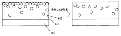
- the ionic liquid 180 when the ionic liquid 180 is mixed and applied to the hard coat liquid for forming the hard coat layer, the ionic liquid 180 in the hard coat layer 170 is collected on the surface layer of the hard coat layer 170 although the antistatic performance is exhibited. (The left figure of FIG. 8). Therefore, when the hard coat layer 170 manufactured in this way is wiped with a waste cloth or the like to which a solvent is attached, or when the film (hard coat layer 170) is wetted with a solvent and then wiped, as shown in FIG. The problem that the aggregated ionic liquid 180 is removed and sufficient antistatic performance cannot be obtained (the right diagram in FIG. 8) has been newly found.
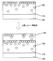
- a hard coat layer 190 having a role of a cover layer is laminated on the hard coat layer 170 mixed with the ionic liquid 180 by sequential application (FIG. 9). ( Figure below).
- the ionic liquid 180 gathered on the surface of the lower hard coat layer 170 is applied to the cover layer 190 provided on the upper layer of the hard coat layer 170 by the solvent used when the cover layer 190 is applied.
- diffusion and elution occurred non-uniformly.
- the concentration of the antistatic agent became non-uniform on the surface of the cover layer 190, resulting in unevenness in antistatic performance.
- the present invention has been made to solve the above-mentioned problems.
- the antistatic agent is removed from the hard coat layer by a solvent of the cover layer or a waste cloth attached to the solvent.
- An optical film having properties that are difficult to remove hereinafter referred to as solvent wiping resistance
- solvent wiping resistance An optical film having properties that are difficult to remove
- the gist of the present invention is as follows. 1. An optical film in which a hard coat layer having a thickness of 1 to 40 ⁇ m is provided on one side of a light transmissive substrate, the hard coat layer containing an ionic liquid composed of a cation and an anion, In the film thickness direction, there is a peak of the abundance of the ionic liquid present in the region from 50 to 700 nm from the interface opposite to the light transmissive substrate of the hard coat layer in the region from the interface to 700 nm.
- An optical film characterized by: 2. 2. The optical film as described in 1 above, wherein the peak half-value width is 25 to 500 nm. 3.
- the ratio of the abundance of the ionic liquid existing in the region from the interface to 50 nm to the abundance of the ionic liquid existing in the region from the interface to 700 nm is 50% or less.
- the cation is at least one cation selected from the group consisting of a quaternary ammonium cation, a quaternary phosphonium cation, an imidazolium cation, a pyridinium cation, and a pyrrolidinium cation.
- the optical film according to any one of 1 to 3. 5. 5.
- the optical film as described in any one of 1 to 4 above, wherein a surface resistance value of the hard coat layer is 1.0 ⁇ 10 13 ⁇ / ⁇ or less.
- the cation is at least one cation selected from the group consisting of a quaternary ammonium cation, a quaternary phosphonium cation, an imidazolium cation, a pyridinium cation, and a pyrrolidinium cation.
- a method for producing an optical film according to 7. 9. A polarizing plate, wherein a polarizing element is provided on a surface of the optical film according to any one of 1 to 6 on the light-transmitting substrate side. 10.
- a display panel comprising the optical film according to any one of 1 to 6 above.
- a display panel comprising the polarizing plate as described in 10 above.
- a display comprising the optical film according to any one of 1 to 6 above.
- the present invention provides an optical film having hardness and solvent wiping resistance of an ionic liquid and capable of maintaining antistatic performance for a long period of time, a manufacturing method thereof, a polarizing plate including the optical film, a display panel, and a display can do.
- FIG. 6 is a graph showing the distribution of sulfur atoms in the depth direction in the hard coat layers of Comparative Examples 1 to 3. It is a conceptual diagram when the conventional hard-coat layer surface which has an ionic liquid is wiped off with the solvent. It is a conceptual diagram at the time of providing the cover layer on the surface of the conventional hard-coat layer which has an ionic liquid.
- optical film according to the present invention will be described first, and then the optical film manufacturing method, polarizing plate, display panel and display according to the present invention will be described.
- (meth) acrylate means acrylate and / or methacrylate
- (meth) acrylic acid means acrylic acid and / or methacrylic acid
- the “hard coat layer” means a layer having a hardness of “H” or higher in a pencil hardness test (4.9 N load) defined in JIS K5600-5-4 (1999).
- the average particle diameter of fine particles means the average particle diameter when particles in a solution are measured by a dynamic light scattering method in the case of fine particles in the composition, It can be measured using a Microtrac particle size analyzer manufactured by Nikkiso Co., Ltd.
- the polymerization average molecular weight Mw is calculated
- An optical film according to the present invention is an optical film in which a hard coat layer having a film thickness of 1 to 40 ⁇ m is provided on one side of a light-transmitting substrate, and the hard coat layer contains an ionic liquid composed of a cation and an anion.
- the ions present in the region of 50 to 700 nm from the interface opposite to the light transmissive substrate of the hard coat layer and in the region from the interface to 700 nm. It is characterized by the presence of a peak in the amount of liquid present.
- the ionic liquid exhibiting antistatic properties is not unevenly distributed in a region having a depth of 50 nm from the surface of the hard coat layer, and is present in a region having a specific depth (50 to 700 nm) from the surface of the hard coat layer.
- the hard coat layer has solvent wiping resistance, and as a result, sufficient antistatic performance can be maintained over a long period of time.
- a peak means the point (maximum point) with much abundance compared with before and after that.
- the ionic liquid it is only necessary that a peak of the ionic liquid exists at the specific depth, and the ionic liquid is smaller than the existing amount of the peak in the region from the surface of the hard coat layer to a depth of 50 nm. May be present, or the ionic liquid may not be present.
- the full width at half maximum of the peak may be 25 to 500 nm.
- the half-value width is within the above range, the ionic liquid is unevenly distributed in a region having a specific depth (50 to 700 nm) from the surface of the hard coat layer (interface opposite to the light-transmitting substrate). It has both high antistatic performance and solvent wiping resistance.
- the ratio of the abundance of the ionic liquid present in the region from the interface to 50 nm to the abundance of the ionic liquid present in the region from the interface to 700 nm It is also possible to make it 50% or less.
- the ratio of the abundance of the ionic liquid existing in the region from the interface to 50 nm to the abundance of the ionic liquid existing in the region from the interface to 600 nm is 50% or less. It is also possible to do.
- the ratio of the amount of the ionic liquid existing in the region from the interface to 50 nm can be 30% or less. Thereby, the antistatic performance of a hard-coat layer can be improved efficiently.
- the proportion of the ionic liquid present in the specific region can be measured as follows using X-ray photoelectron spectroscopy (XPS) (trade name ESCA-3400 manufactured by KRATOS).
- XPS is an analytical method for irradiating the surface of a solid sample with X-rays and measuring the kinetic energy of photoelectrons generated by the photoelectric effect. By measuring the observation intensity of the photoelectron peak, the elements of the sample surface are measured. The type and concentration can be measured.
- an Mg anode was used as the X-ray source.
- a sample (hard coat layer) is etched by ion sputtering (irradiated with Ar +, and a high-speed ion gun (Kaufman type ion gun) is used as a sputtering ion gun).
- the part is exposed, and XPS measurement is performed on the exposed part at the specific depth.
- the peaks peculiar to each element (Binding Energy (BE) unit [eV]) observed in the exposed portion of the specific depth are used for C (265 to 305), N (380 to 420), O (510). 550), S (145 to 185), and F (665 to 705) peaks, the abundance of the five elements is calculated from the respective peak areas, and the total of the calculated abundances of the five elements is 100.
- BE Biting Energy
- the XPS measurement is performed from the interface of the hard coat layer to the region to be measured (700 nm). Then, paying attention to a specific element included in only the ionic liquid to be measured among the five elements, the total amount S1 of the content of the specific element from the interface to the region to be measured (700 nm), and the interface From the total amount S2 of the specific element in the region up to 50 nm to obtain the ratio of S2 to S1, the region from the interface to the existing amount of the ionic liquid existing in the predetermined region (700 nm) from the interface to 50 nm The ratio of the abundance of the ionic liquid present in is found. In addition to this, there is a technique in which an arbitrary part of the film cross section is subjected to EDX (elemental analysis).
- the peak of the ionic liquid is present in the region of 50 to 700 nm from the surface of the hard coat layer, but from the viewpoint of solvent wiping resistance and antistatic performance, it is 80% from the surface of the hard coat layer. It is preferably ⁇ 700 nm, more preferably 100 to 600 nm.
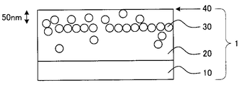
- FIG. 1 is a schematic view showing an example of a cross section of the first embodiment of the optical film according to the present invention.
- a hard coat layer 20 having a thickness of 1 to 20 ⁇ m is provided on one surface side of a light-transmitting substrate 10.
- the hard coat layer 20 contains an ionic liquid 30, and in the film thickness direction of the hard coat layer 20 (hereinafter also referred to as “depth direction”), what is the light transmissive substrate 10 of the hard coat layer 20?
- a peak of the abundance of the ionic liquid 30 existing in the region from the interface 40 to 700 nm is present in the region of 50 to 700 nm from the opposite interface 40 (hereinafter also simply referred to as “the surface of the hard coat layer”).
- the ionic liquid 30 that exhibits antistatic properties is not unevenly distributed in the region from the interface 40 to 50 nm, and is in a region of a specific depth from the interface 40 of the hard coat layer 20.
- the hard coat layer 20 has a solvent wiping resistance and can maintain sufficient antistatic performance over a long period of time.
- the vertical and horizontal dimension ratios and the dimension ratios between the layers are exaggerated as appropriate instead of the actual dimensions.
- the light transmissive substrate and the hard coat layer which are essential components of the optical film according to the present invention, and the low refractive index layer that can be provided as necessary will be described.
- the light-transmitting substrate used in the optical film of the present invention serves as a laminate or support for various functional layers. Therefore, the kind of the light-transmitting substrate is not particularly limited as long as it has transparency to visible light and various functional layers can be laminated.
- polyesters such as polyethylene terephthalate (PET: refractive index 1.575) and polyethylene naphthalate (PEN); polyolefins such as cyclic polyolefin, polyethylene, polypropylene, and polystyrene; polychlorinated Vinyl resins such as vinyl and polyvinylidene chloride; polycarbonate; acrylic resins such as polymethacrylate; cellulose resins such as diacetyl cellulose, triacetyl cellulose (TAC: refractive index 1.475), cellulose acetate; nylon-6, nylon-6 Examples thereof include polyamide resins such as 6; polyimide resins; films made of resins such as polyvinyl alcohol, ethylene vinyl alcohol, polyether sulfone, or polyether ketone.
- PET polyethylene terephthalate
- PEN polyethylene naphthalate
- polyolefins such as cyclic polyolefin, polyethylene, polypropylene, and polystyrene
- an amorphous olefin polymer (Cyclo-Olefin-Polymer: COP) film having an alicyclic structure can also be used as a light-transmitting substrate.
- This is a base material on which a norbornene polymer, a monocyclic olefin polymer, a cyclic conjugated diene polymer, a vinyl alicyclic hydrocarbon polymer resin, etc. are used.
- a norbornene polymer a monocyclic olefin polymer, a cyclic conjugated diene polymer, a vinyl alicyclic hydrocarbon polymer resin, etc.
- the light-transmitting substrate those made of the above materials can be used alone, or the same kind or different kinds can be laminated.
- a coating called an anchor agent or primer is applied. It may be performed in advance.
- the light transmittance in the visible region is preferably 80% or more. Further, having transparency is preferably colorless and transparent, but is not necessarily limited to being colorless and transparent, and is colored and transparent as long as it does not interfere with the object of the present invention. Also good.
- the light transmittance in the visible region is preferably as high as possible, but the final product requires a light transmittance of 50% or more. If the light transmittance is 80% as a conductive substrate, it is suitable for the purpose. Of course, as the light transmittance is higher, a plurality of light transmissive substrates can be laminated. Therefore, the light transmittance of a single layer of the light transmissive substrate is more preferably 85% or more, and particularly preferably 90%. % Or more. In order to improve the light transmittance, reducing the thickness is also an effective means.
- the thickness of the light-transmitting substrate is not particularly limited as long as the transparency is satisfied, but is preferably in the range of about 12 to 300 ⁇ m from the viewpoint of workability. There exists an advantage that it is easy to handle in a manufacturing process as thickness is 12 micrometers or more. On the other hand, if the thickness is 300 ⁇ m or less, sufficient flexibility as a film is obtained, enabling continuous winding in each step, and good workability when laminating a plurality of light-transmitting substrates. is there. If necessary, known additives such as an antistatic agent, an ultraviolet absorber, an infrared absorber, a plasticizer, a lubricant, a colorant, an antioxidant, a flame retardant, etc. are added as the light transmissive substrate. However, it can also be used with functions added.
- the hard coat layer of the optical film according to the present invention includes an ionic liquid composed of a cation and an anion, and in the film thickness direction of the hard coat layer having a thickness of 1 to 40 ⁇ m, Has a peak of the abundance of the ionic liquid present in the region from 50 to 700 nm from the opposite interface in the region from 700 to 700 nm.
- the hard coat layer is usually composed of a cured product of a curable resin composition for a hard coat layer containing at least a curable resin and an ionic liquid (hereinafter also simply referred to as “HC layer composition”).
- the hard coat layer of the optical film according to the present invention is made of a cured product of the HC layer composition containing a curable resin and an ionic liquid, it has high antistatic performance and hardness. Furthermore, since it has the distribution of the specific ionic liquid in the depth direction of the hard coat layer, it has solvent wiping resistance and can maintain sufficient antistatic performance over a long period of time.
- the curable resin, the ionic liquid which are essential components of the composition for the HC layer, and other components such as a solvent which may be included as necessary will be described in order.
- curable resin In the present invention, monomers, oligomers and prepolymers having one or more functional groups that can be cured by heat and / or ionizing radiation can be used as the curable resin.
- functional groups include condensable groups and reactive groups exemplified by hydroxyl groups, acid anhydride groups, carboxyl groups, amino groups, imino groups, epoxy groups, glycidyl groups, or isocyanate groups.
- alkenyl groups having 2 to 6 carbon atoms such as vinyl group, propenyl group, isopropenyl group, butenyl group and allyl group; alkynyl groups having 2 to 6 carbon atoms such as ethynyl group, propynyl group and butynyl group; vinylidene and the like
- alkenyl groups having 2 to 6 carbon atoms such as vinyl group, propenyl group, isopropenyl group, butenyl group and allyl group
- alkynyl groups having 2 to 6 carbon atoms such as ethynyl group, propynyl group and butynyl group
- vinylidene and the like examples thereof include a polymerizable group such as an alkenylidene group having 2 to 6 carbon atoms or a (meth) acryloyl group (meaning a methacryloyl group or an acryloyl group).
- a polymerizable group is particularly
- Examples of the curable resin having a polymerizable group include a compound having a radical polymerizable group.
- the compound having a radical polymerizable group include (meth) acrylate monomers, polyester monomers, polyether monomers, epoxy monomers, urethane monomers, alkyd monomers, spiroacetal monomers having a relatively low molecular weight (for example, molecular weight of 80 to 2000).
- (Meth) acrylic acid esters of polyfunctional compounds such as polybutadiene monomer, polythiol polyene monomer, polyhydric alcohol, and the like.
- (meth) acrylate monomers include ethyl (meth) acrylate, ethylhexyl (meth) acrylate, trimethylolpropane tri (meth) acrylate, hexanediol (meth) acrylate, tripropylene glycol di (meth) acrylate, diethylene glycol di (Meth) acrylate, pentaerythritol tri (meth) acrylate, dipentaerythritol hexa (meth) acrylate, 1,6-hexanediol di (meth) acrylate, neopentyl glycol di (meth) acrylate, and the like.
- monofunctional or polyfunctional monomers such as styrene, methylstyrene, and N-vinylpyrrolidone, or monomers such as bisphenol type epoxy compounds, novolac type epoxy compounds, aromatic vinyl ethers, and aliphatic vinyl ethers may be used.
- Polyfunctional monomers such as tri (meth) acrylate, dipentaerythritol tetra (meth) acrylate, dipentaerythritol penta (meth) acrylate, pentaerythritol hexa (meth) acrylate, and epoxy such as bisphenol type epoxy resin and novolac type epoxy compound
- Cyclic ether bond-containing oligomers such as vinyl ether oligomers such as aliphatic oligomers, fatty acid vinyl ethers and aromatic vinyl ethers may be used.
- thermosetting resin a monomer or oligomer having a thermosetting group
- the thermosetting group is, for example, an alkoxy group, a hydroxyl group, a carboxyl group, an amino group, an epoxy group, an isocyanate group, an aziridine group, an oxazoline group, an aldehyde group, a carbonyl group, a hydrazine group, a vinyl group, a cyano group, a methylol group, or An active methylene group etc. are mentioned.
- thermosetting group has a blocking agent bonded to a reactive functional group such as a block isocyanate group, and when heated, the decomposition reaction of the blocking agent proceeds to increase the polymerizability and crosslinkability.
- a reactive functional group such as a block isocyanate group
- an organometallic compound such as an organosilicon compound (silicon alkoxide or silane coupling agent), an organotitanium compound (titanate coupling agent), or an organoaluminum compound that is usually used as a coupling agent is used. May be.
- organosilicon compound include methyltrimethoxysilane, methyltriethoxysilane, methyltrimethoxyethoxysilane, 3-glycidoxypropyltrimethoxysilane, and 3-aminopropyltrimethoxysilane.
- the organosilicon compound having a reactive group is easily cured and strongly bonded to another monomer or oligomer, so that the hardness of the resulting hard coat layer is improved.
- the organic titanium compound include tetramethoxy titanium and tetraethoxy titanium.
- a reactive polymer having a (meth) acrylate group in the main chain or side chain and having a weight average molecular weight of 20,000 or more can be preferably used.
- These reactive polymers can be purchased as commercial products such as “macromonomer” manufactured by Toagosei Co., Ltd., for example.
- a copolymer of methyl (meth) acrylate and glycidyl methacrylate is prepared in advance, and then the glycidyl group of the copolymer and the carboxyl group of (meth) acrylic acid are condensed (meta It is also possible to obtain reactive polymers having acrylate groups.
- the optical film can be improved in terms of film formability for complex shapes and volume shrinkage during curing. Curling and warping can be reduced.
- the molecular weight of curable resin is 1000 or less from a viewpoint of making curable resin permeate
- curable resins include pentaerythritol tri (meth) acrylate and dipentaerythritol hexa (meth) acrylate.
- the curable resin those described above can be used alone or in combination of two or more.
- the content of the curable resin in the composition for the HC layer may be adjusted as necessary, but it can provide sufficient hardness as a hard coat layer and contain a sufficient amount of ionic liquid. From the viewpoint of achieving both antistatic performance and hardness, the range of 50 to 99% by mass is preferable with respect to the total mass of the HC layer composition excluding the solvent, and the range of 70 to 97% by mass is more preferable.
- the ionic liquid means a liquid consisting of a cation and an anion, which is in a liquid state at room temperature (23 to 25 ° C.).
- the ionic liquid used in the present invention only needs to have antistatic properties.
- the ionic liquid has high ionic conductivity, high thermal stability, moderate viscosity, vapor Those having a low pressure, those having no flammability and flammability, those having a wide liquid temperature range, and the like may be appropriately selected and used.
- the HC liquid composition contains the ionic liquid.
- the second HC layer composition does not have to contain an ionic liquid.
- the cation is at least one cation selected from the group consisting of a quaternary ammonium cation, a quaternary phosphonium cation, an imidazolium cation, a pyridinium cation, and a pyrrolidinium cation. It is preferable from the viewpoint of solubility and antistatic properties. Furthermore, the cation is more preferably a quaternary phosphonium cation, an imidazolium cation or a pyridinium cation from the viewpoints of solubility and antistatic properties. Of these, quaternary phosphonium cations are preferred because of their good thermal stability, light resistance, and transparency.
- Examples of the cation include a quaternary ammonium cation (the following formula (I)), a quaternary phosphonium cation (the following formula (II)), an imidazolium cation (the following formula (III)), Pyridinium cation (following formula (IV)), pyrrolidinium cation (following formula (V)) and the like can be mentioned.
- R 1 to R 11 may be the same or different and each represents a saturated aliphatic group, or R 3 and R 4 together with the nitrogen atom to which A hetero ring may be formed, provided that the sum of the carbon numbers of R 1 to R 4 and R 5 to R 8 is 6 or more, the sum of the carbon numbers of R 9 and R 10 is 3 or more, and R 11 has 2 or more carbon atoms, and R 12 and R 13 are each independently a saturated aliphatic group having 1 to 12 carbon atoms.
- the saturated aliphatic group represented by R 1 to R 13 may be linear or branched. Examples include methyl, ethyl, propyl, isopropyl, butyl, isobutyl, sec-butyl, tert-butyl, hexyl, octyl, decyl and the like. Further, examples of the group include a group containing a heteroatom such as S or O by a bond represented by —S— or —O— (provided that R 11 represents a carbon number among them) Is 2 or more).
- the saturated aliphatic group is preferably an alkyl group having 1 to 8 carbon atoms, and more preferably an alkyl group having 1 to 4 carbon atoms.
- Examples of the aliphatic heterocycle formed by R 3 and R 4 together with the nitrogen atom to which they are bonded include pyrrolidine ring, piperidine ring, diazepine ring, piperazine ring, morpholine ring and the like.
- a membered aliphatic heterocycle is preferred.
- R 1 and R 2 are a methyl group or an ethyl group
- R 3 is an alkyl group having 1 to 4 carbon atoms
- R 4 is an alkyl group having 1 to 8 carbon atoms.
- the group cation is preferred.
- the quaternary ammonium cation represented by the formula (I) is a cation (TMPA) in which R 1 to R 3 are methyl groups and R 4 is a propyl group; R 1 and R 2 are methyl groups, R 3 Is particularly preferably a cation in which R 4 is an isopropyl group and R 4 is a hexyl group; R 1 is a methyl group, R 2 and R 3 are ethyl groups, and R 4 is a 2-methoxyethyl group.
- TMPA cation
- R 1 to R 3 are methyl groups and R 4 is a propyl group
- R 1 and R 2 are methyl groups
- R 1 is a methyl group
- R 2 and R 3 are ethyl groups
- R 4 is a 2-methoxyethyl group.
- R 2 is an ethyl group, a cation or R 3 and R 4 form a pyrrolidine ring together with the nitrogen atom attached, R 1 is methyl, R 2 is butyl, R 3 and R 4 bond A cation (BMP) that forms a pyrrolidine ring together with the nitrogen atom to be formed is preferred.
- BMP cation
- R 5 and R 6 are each independently a methyl group or an ethyl group
- R 7 is an alkyl group having 1 to 4 carbon atoms
- R 8 is a carbon number. Cations that are 1 to 8 alkyl groups are preferred.
- the imidazolium cation represented by the formula (III) is preferably a cation in which R 9 and R 10 are each independently an alkyl group having 1 to 4 carbon atoms. And, R 9 is a methyl group, the cation (EMI) and R 10 is an ethyl group, R 9 is a methyl group, the cation R 10 is butyl group (BMI) is particularly preferred.
- the cation preferably R 11 is an alkyl group having 2-8 carbon atoms, the cation R 11 is a butyl group (BP) is particularly preferred.
- the pyrrolidinium cation represented by the formula (V) is preferably a cation in which R 12 and R 13 are alkyl groups having 1 to 8 carbon atoms, and a cation in which R 12 is a butyl group is particularly preferable.
- Quaternary ammonium-based cations include symmetrical ammoniums such as tetramethylammonium, tetraethylammonium, tetrapropylammonium, etc., and ethyltrimethylammonium, vinyltrimethylammonium, triethylmethylammonium, triethylpropylammonium, diethyldimethylammonium, tributylethyl.
- Ammonium triethylisopropylammonium, N, N-dimethylpyrrolidinium, N-methyl-N-ethylpyrrolidinium, N-methyl-N-propylpyrrolidinium, N-methyl-N-butylpyrrolidinium, N- Methyl-N-ethylpiperidinium, N-methyl-N-propylpiperidinium, N-methyl-N-butylpiperidinium, triethylmethoxymethylammoni Dimethylethylmethoxyethylammonium, dimethylethylmethoxymethylammonium, diethylmethylmethoxyethylammonium, diethylmethylmethoxymethylammonium, etc.
- the carbon number of the shortest substituent is 50% or more and less than 100% of the longest substituent.
- Other quaternary ammonium cations include trimethylpropylammonium, trimethylisopropylammonium, butyltrimethylammonium, allyltrimethylammonium, hexyltrimethylammonium, octyltrimethylammonium, dodecyltrimethylammonium, triethylmethoxyethoxymethylammonium, dimethyldipropyl.
- Asymmetric ammonium such as ammonium is also included.
- a quaternary phosphonium salt is preferable. Specifically, triethyl (methoxymethyl) phosphonium bis (trifluoromethylsulfonyl) imide, triethyl (methoxymethyl) phosphonium.
- Tetrafluoroborate triethyl (methoxymethyl) phosphonium hexafluorophosphate, triethyl (methoxymethyl) phosphonium trifluoromethanesulfonate, triethyl (methoxymethyl) phosphonium bis (fluorosulfonyl) imide, triethyl (methoxymethyl) phosphonium thiocyanate, Triethyl (methoxymethyl) phosphonium dicyanamide, triethyl (methoxymethyl) phosphonium dialkyl phosphate, triethyl 2-methoxyethyl) phosphonium bis (trifluoromethylsulfonyl) imide, triethyl (methoxymethyl) phosphonium tetrafluoroborate, triethyl (2-methoxyethyl) phosphonium tetrafluoroborate, triethyl (2-methoxyethyl) phosphon
- triethyl (methoxymethyl) phosphonium bis (trifluoromethylsulfonyl) imide Triethyl (methoxymethyl) phosphonium tetrafluoroborate, triethyl (methoxymethyl) phosphonium dicyanamide, triethyl (2-methoxyethyl) phosphonium bis (trifluoromethylsulfonyl) imide, triethyl (2-methoxyethyl) phosphonium tetrafluoro Borate, triethyl (2-methoxyethyl) phosphonium dicyanamide, tri-n-butyl (methoxymethyl) phosphonium bis (trifluoromethylsulfonyl) i De, tri -n- butyl (2-methoxyethyl) phosphonium bis (trifluoromethylsulfonyl) imide low viscosity, from the viewpoint of base resistance and heat
- ionic liquids composed of imidazolium cations and anions include 1,3-dimethylimidazolium chloride, 1,3-dimethylimidazolium dimethyl phosphate, 1-ethyl-3-methylimidazolium chloride, 1 -Ethyl-3-methylimidazolium bromide, 1-ethyl-methylimidazolium iodide, 1-ethyl-3-methylimidazolium trifluoromethanesulfonate, 1-ethyl-3-methylimidazolium p-toluene Sulfonate, 1-ethyl-3-methylimidazolium ethyl sulfate, 1-ethyl-3-methylimidazolium 2-methyl (2-methoxyethoxy) ethyl sulfate, 1-ethyl-3-methylimidazolium dicine Amamide, 1-D 3-methylimidazolium tetrafluoroborate, 1-e
- ionic liquids composed of pyridinium cations and anions include 1-ethylpyridinium chloride, 1-ethylpyridinium bromide, 1-butylpyridinium chloride, 1-butylpyridinium bromide, 1-butylpyridinium hexafluoro Phosphate, 1-butyl-4-methylpyridinium bromide, 1-butyl-4-methylpyridinium hexafluorophosphate, 1-ethyl-3-methylpyridinium ethylsulfate, 1-ethyl-3- (hydroxymethyl) pyridinium Examples thereof include ethyl sulfate. Of these, 1-ethyl-3- (hydroxymethyl) pyridinium ⁇ ethyl sulfate is preferable because it exhibits high ionic conductivity.
- ionic liquid comprising a pyrrolidinium cation and an anion
- ionic liquid comprising a pyrrolidinium cation and an anion
- 1-butyl-1-methylpyrrolidinium bis (trifluoromethanesulfonyl) imide examples include 1-butyl-1-methylpyrrolidinium bis (trifluoromethanesulfonyl) imide.
- anion of the ionic liquid examples include halogen, triflate, tetrafluoroborate and hexafluorophosphate.
- the content of the ionic liquid is preferably 1% by mass or more, preferably 3% by mass or more, based on the total mass of the composition for the HC layer excluding the solvent, from the viewpoint of imparting sufficient antistatic properties to the hard coat layer. It is preferable that In addition, the content of the ionic liquid is 50% by mass or less based on the total amount of the composition for the HC layer excluding the solvent from the viewpoint of increasing the content of the curable resin and obtaining sufficient hardness of the hard coat layer. Is preferable, and it is more preferable that it is 30 mass% or less.
- the film thickness of the hard coat layer is 1 to 40 ⁇ m, preferably 1 to 20 ⁇ m.
- the surface resistance value of the hard coat layer is preferably 1.0 ⁇ 10 13 ⁇ / ⁇ or less, and more preferably 1.0 ⁇ 10 11 ⁇ / ⁇ or less.
- the composition for the HC layer includes, in addition to the curable resin and ionic liquid, which are essential components, a solvent, a photoinitiator, a photosensitizer, a photopolymerization accelerator, fine particles, and the like as necessary. Other components may be included.
- the solvent is not particularly limited as long as it is a solvent that can uniformly dissolve or disperse at least components other than the solvent such as curable resin and ionic liquid, and conventionally known solvents can be used.
- the solvent include alcohols such as methanol, ethanol and isopropyl alcohol; ketones such as acetone, methyl ethyl ketone (MEK), methyl isobutyl ketone (MIBK) and cyclohexanone; esters such as methyl acetate, ethyl acetate and butyl acetate; Ethers such as dioxane, tetrahydrofuran and diisopropyl ether; glycols such as ethylene glycol and propylene glycol; aliphatic hydrocarbons such as hexane; glycol ethers such as ethyl cellosolve and ethyl carbitol; halogenated hydrocarbons; Aromatic hydrocarbons such as xy
- the light transmissive substrate is a TAC substrate
- a solvent having permeability to the TAC substrate (hereinafter, “ It is preferable to use a “permeable solvent”.
- the permeable solvent dissolves or swells the TAC substrate, and the curable resin easily penetrates into the TAC substrate. This is presumably because the interface becomes unclear and the difference in refractive index at the interface between the TAC substrate and the hard coat layer is reduced.
- the permeable solvent for example, ketones such as methyl ethyl ketone are preferable.
- the solvent those described above may be used alone or in combination of two or more. What is necessary is just to adjust suitably content of the solvent in the composition for HC layers so that each component other than a solvent can melt
- the content of the solvent is preferably 20 to 99.5% by mass with respect to the total mass of the HC layer composition, for example, from the viewpoint of dispersion stability and long-term storage stability of the HC layer composition. It is preferably 30 to 70% by mass.
- photoinitiator When a resin curable by ionizing radiation is used as the curable resin, it is desirable to use a photoinitiator in order to initiate polymerization.
- the photoinitiator is not particularly limited, and examples thereof include acetophenones, benzophenones, ketals, anthraquinones, disulfide compounds, thiuram compounds, and fluoroamine compounds.
- 1-hydroxy-cyclohexyl-phenyl ketone 2-methyl-1- [4- (methylthio) phenyl] -2-morpholinopropan-1-one, benzyldimethylketone, 1- (4-dodo Tesylphenyl) -2-hydroxy-2-methylpropan-1-one, 2-hydroxy-2-methyl-1-phenylpropan-1-one, 1- (4-isopropylphenyl) -2-hydroxy-2-methyl
- Examples thereof include propan-1-one and benzophenone.
- 1-hydroxy-cyclohexyl-phenyl ketone and 2-methyl-1- [4- (methylthio) phenyl] -2-morpholinopropan-1-one are polymerized by irradiation with ionizing radiation even in a small amount.
- any one of the above photoinitiators can be used alone or in combination.
- a commercial product of a photoinitiator for example, 1-hydroxy-cyclohexyl-phenyl-ketone is available from Ciba Japan Co., Ltd. under the trade name Irgacure 184.
- the content of these photoinitiators is usually about 0.1 to 20 parts by mass with respect to 100 parts by mass of the curable resin having a polymerizable group in the HC layer composition.
- the HC layer composition may contain a photosensitizer and a photopolymerization accelerator as necessary.
- the photosensitizer and photopolymerization accelerator include benzoin compounds such as benzoin, benzoin methyl ether, benzoin ethyl ether, benzoin isopropyl ether, ⁇ -methylbenzoin, ⁇ -phenylbenzoin; anthraquinone, methylanthraquinone, and the like.
- Anthraquinone compounds benzyl; diacetyl; phenyl ketone compounds such as acetophenone and benzophenone; sulfide compounds such as diphenyl disulfide and tetramethylthiuram sulfide; ⁇ -chloromethylnaphthalene; halogenated hydrocarbons such as anthracene and hexachlorobutadiene and pentachlorobutadiene; There are thioxanthone, n-butylamine, triethylamine, tri-n-butylphosphine and the like.
- a benzophenone or a thioxanthone photosensitizer for the acetophenone photopolymerization initiator.
- the content thereof may be appropriately adjusted.
- the content may be 10 to 300% by mass with respect to the mass of the photoinitiator.
- fine particles such as silica fine particles used in conventionally known hard coat layers may be used in order to increase the hardness of the hard coat layer.
- reactive silica fine particles having a functional group such as a polymerizable group capable of being polymerized or cross-linked with the functional group of the curable resin on the surface of the silica fine particles are preferable from the viewpoint of increasing the hardness of the hard coat layer.
- conventionally known fine particles may be used.
- reactive silica fine particles described in JP-A-2008-165040 can be used.
- the average particle diameter of the fine particles is preferably 1 nm or more from the viewpoint of dispersibility.
- fine-particles is 100 nm or less from a viewpoint of ensuring the transparency of a hard-coat layer. From these viewpoints, the average particle size of the fine particles is more preferably 10 to 50 nm.
- the shape of the fine particles is not particularly limited, and examples thereof include spherical shapes and needle shapes. When the fine particles are used, the content thereof may be appropriately adjusted. For example, the content may be 10 to 60% by mass with respect to the total mass of the HC layer composition excluding the solvent.
- a known dispersant may be used in order to improve the dispersibility of the fine particles.
- a dispersant having an anionic polar group such as a carboxyl group, a phosphate group and a hydroxyl group is preferable because of its good affinity with fine particles.
- the dispersant having an anionic polar group include, for example, trade names Disperbyk-110, Disperbyk-111, Disperbyk-116, Disperbyk-140, Disperbyk-161, Disperbyk-162, Disperbyk- manufactured by Big Chemie Japan Co., Ltd.
- Disperbyk-163 is particularly preferable because of its good dispersibility.
- the content thereof may be adjusted as appropriate.
- the content may be 1 to 300% by mass with respect to the mass of the fine particles.
- a stain-proofing agent a water-repellent agent, an oil-repellent agent, an anti-fingerprint agent, a leveling agent, a fluidity-adjusting agent, a hardness-adjusting agent
- one or more components selected from the group consisting of an antiglare agent, a refractive index adjusting agent, and a hardening agent may be used.
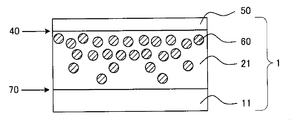
- FIG. 2 is a cross-sectional view schematically showing an example of the second embodiment of the optical film according to the present invention.
- a refractive index gradient hard coat layer 21 and a low refractive index layer 50 having a film thickness of 1 to 40 ⁇ m are provided on one side of the triacetyl cellulose substrate 11 from the side of the triacetyl cellulose substrate 11. ing.
- the high refractive index fine particles 60 are present so as to be closer to the interface 40 side and to be smaller as the surface is closer to the triacetylcellulose substrate 11 side.
- a large amount of ionic liquid is present in a specific depth region from the surface of the hard coat layer as in FIG. Therefore, the ionic liquid is omitted.
- the refractive index of the refractive index gradient hard coat layer means the refractive index of the interface on the side opposite to the base material of the refractive index gradient hard coat layer. It can be confirmed by the following method that the refractive index is inclined in the refractive index gradient hard coat layer.
- the refractive index gradient hard coat layer is etched by argon sputtering to expose a specific depth portion of the refractive index gradient hard coat layer, and the content of high refractive index fine particles in the exposed portion is determined by an X-ray photoelectron spectrometer ( XPS). By this method, the abundance distribution of the high refractive index fine particles in the depth direction of the refractive index gradient hard coat layer is specified.
- the refractive index at each depth point of the gradient refractive index hard coat layer correlates with the abundance of high refractive index fine particles, so the abundance distribution of high refractive index fine particles in the depth direction of the gradient refractive index hard coat layer is inclined. By confirming that the refractive index is confirmed, it can be confirmed that the refractive index is inclined.
- an optical film was embedded using a thermosetting resin, and an ultrathin section having a thickness of 80 nm was prepared from the embedded optical film using a LEICA ultramicrotome and observed with a transmission electron microscope (TEM). Can also be measured.
- High refractive index fine particles mean fine particles having a refractive index of 1.50 to 2.80.
- the refractive index of the surface of the hard coat layer opposite to the substrate was obtained by measuring the absolute reflectance at a wavelength of 380 to 780 nm using a spectrophotometer (UV-3100PC manufactured by Shimadzu Corporation). It can obtain
- the high refractive index fine particles 60 have the above-described distribution, the low refractive index layer 50 provided on the refractive index gradient hard coat layer 21 and the refractive index gradient are provided.
- the difference in refractive index from the vicinity of the interface 40 of the hard coat layer 21 is increased, and the antireflection performance is high.
- the high refractive index fine particles 60 having a relatively high refractive index and the refractive index are relatively low as compared with the case where the hard coat layer in which the high refractive index fine particles 60 are uniformly distributed in the layer is provided on the triacetyl cellulose substrate.
- the optical film of the second aspect also has the same ionic liquid distribution as the optical film of the first aspect, it has high antistatic performance and solvent wiping resistance.
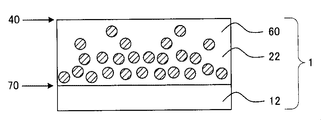
- FIG. 3 is a cross-sectional view schematically showing an example of the third aspect of the optical film according to the present invention.
- a refractive index gradient hard coat layer 22 having a thickness of 1 to 40 ⁇ m is provided on one surface side of a polyethylene terephthalate substrate 12.
- the high refractive index fine particles 60 are present so as to be closer to the interface 70 side and to be smaller as it is closer to the interface 40 side.
- the high refractive index fine particles 60 have the distribution described above, so that the region of the hard coat layer 22 on the polyethylene terephthalate substrate 12 side and the polyethylene terephthalate substrate 12 The difference in refractive index near the interface 70 is reduced, and the generation of interference fringes at the interface 70 can be suppressed.
- the reason is presumed as follows. That is, when the high refractive index fine particles 60 are uniformly distributed in the hard coat layer, the ratio of the resin having a relatively low refractive index to the polyethylene terephthalate substrate 12 having a relatively high refractive index increases.
- the optical film of the third aspect also has the same ionic liquid distribution as the optical film of the first aspect, it has high antistatic performance and solvent wiping resistance.
- fine-particles As said high refractive index microparticles
- metal oxide fine particles include titanium oxide (TiO 2 , refractive index: 2.71), zirconium oxide (ZrO 2 , refractive index: 2.10), cerium oxide (CeO 2 , refractive index: 2).
- tin oxide SnO 2 , refractive index: 2.00
- antimony tin oxide ATO, refractive index: 1.75 to 1.85
- indium tin oxide ITO, refractive index: 1.95)
- phosphorus tin compound PTO, refractive index: 1.75 to 1.85
- antimony oxide Sb 2 O 5 , refractive index: 2.04
- aluminum zinc oxide AZO
- gallium zinc An oxide etc. are mentioned.
- metal oxide conductive fine particles such as PTO: Phosphorus tin compound (for example, trade name EP SP-2: manufactured by Mitsubishi Materials Corporation) are preferable because of excellent transparency. .
- ATO antimony tin oxide (for example, trade name SN-100P: manufactured by Ishihara Sangyo Co., Ltd.) or ITO: indium tin oxide (for example, trade name SUFP: Sumitomo Metal Mining Co., Ltd.)
- metal oxide conductive fine particles such as (manufactured) or the like, dust adhesion preventing property can be imparted, which is preferable.
- the average particle diameter of the high refractive index fine particles is preferably from 1 to 100 nm, more preferably from 10 to 50 nm, from the viewpoint of dispersibility and transparency of the gradient refractive index hard coat layer, as in the case of the fine particles of the first embodiment.
- the shape of the high refractive index fine particle is not particularly limited, and examples thereof include a spherical shape and a needle shape.
- the high refractive index fine particles may be used singly or may be used in combination of two or more kinds by appropriately selecting the material, shape and average particle diameter.
- the distribution of the high refractive index fine particles in the refractive index gradient hard coat layer is controlled, and the refractive index gradient hard coat layer and the light transmissive substrate The effect of reducing the refractive index difference at the interface and suppressing the generation of interference fringes at the interface can be obtained.
- fine particles having a low refractive index such as silica fine particles and metal fluorides, are used.
- the distribution of fine particles having a low refractive index is controlled like the high refractive index fine particles in FIG. 2 or FIG.
- the difference in refractive index between the hard coat layer and the light-transmitting substrate is preferably 0.03 or less in absolute value.
- the refractive index of the hard coat layer was measured from the reflectance curve obtained by measuring the absolute reflectance at a wavelength of 380 to 780 nm using a spectrophotometer (UV-3100PC manufactured by Shimadzu Corporation). The value of the refractive index obtained using.
- a low refractive index layer 50 is provided on the interface 40 of the refractive index gradient hard coat layer 21.
- the closer to the interface 40 side the more high refractive index fine particles 60 exist, and the refractive index difference between the gradient refractive index hard coat layer 21 and the low refractive index layer 50 can be increased. it can. Therefore, the optical film of the second aspect has high antireflection performance.
- the low refractive index layer can be a conventionally known low refractive index layer.
- a low refractive index layer containing silica fine particles, magnesium fluoride, and a fluorine-based resin described in JP2008-165040A can be used.
- the method for producing an optical film according to the present invention is not particularly limited as long as the hard coat layer can be formed so as to have the above-described ionic liquid distribution in a specific depth direction from the surface of the hard coat layer.
- the following method is preferable from the viewpoint of easily forming the hard coat layer having the above-described ionic liquid distribution. That is, the method for producing an optical film according to the present invention includes (i) a step of preparing a light-transmitting substrate, (ii) an ionic liquid composed of a cation and an anion, a first curable resin, and a first solvent.
- a first hard coat layer curable resin composition containing an ionic liquid (hereinafter referred to as “first HC layer composition”) is used as a second hard coat.
- first HC layer composition a first hard coat layer curable resin composition containing an ionic liquid
- second HC layer composition For the first HC layer from the light-transmitting substrate side so as to be positioned on the light-transmitting substrate side from the curable resin composition for the layer (hereinafter referred to as “second HC layer composition”).
- the ionic liquid is less likely to bleed out to the surface of the hard coat layer.
- a hard coat layer having a distribution can be easily formed. Therefore, the obtained optical film has both hardness and solvent wiping resistance.
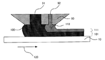
- FIG. 4 is a schematic view showing an example of a simultaneous coating method using an extrusion type die coater.
- the first HC layer composition 100 and the second HC layer composition 110 are respectively formed on the light transmissive substrate 10 from the slits 91 and 92 of the die coater head 80. Are simultaneously applied adjacent to each other so as to be positioned closer to the light transmissive substrate 10 than the second HC layer composition 110, and the first HC layer composition coating 101 and the second HC layer composition It is set as the coating film 111 of a composition.
- the first HC layer composition 100 and the second HC layer composition 110 are integrally integrated to form one hard coat layer.
- the composition and the coating film are color-coded.
- the light transmissive substrate described in the optical film is prepared.
- the respective compositions are prepared.
- the first HC layer composition located on the light transmissive substrate side contains an ionic liquid, a first curable resin, and a first solvent.
- the second HC layer composition located on the first HC layer composition includes a second curable resin and a second solvent. What was demonstrated by the said optical film should just be used for each component.
- the hard coat layer having the distribution of the ionic liquid described above that the viscosity of the second HC layer composition is larger than the viscosity of the first HC layer composition Easy to form.
- the adjustment method of the viscosity of the 1st and 2nd composition for HC layers is not specifically limited, Usually, a viscosity is adjusted with content of a solvent. In addition, the viscosity may be adjusted according to the type and molecular weight of the curable resin.
- the viscosity of the first HC layer composition and the second HC layer composition is, for example, MCR301 manufactured by Anton Paar, the measurement jig is PP50, the measurement temperature is 25 ° C., and the shear rate is 10,000.
- An appropriate amount of the composition to be measured can be dropped on the stage under the condition of [1 / s] and measured.
- the type, molecular weight, and number of functional groups of the curable resin may be the same or different.
- the types of solvents may be the same or different.
- the other components may be the same in the two types of compositions. Good or different. If the composition for the first HC layer and the composition for the second HC layer are the same except for the ionic liquid, it is easy to obtain a hard coat layer having no interface in the layer.
- the cation in the ionic liquid contained in the first HC layer composition, is a quaternary ammonium cation, a quaternary phosphonium cation, an imidazolium cation, or a pyridinium cation.
- One or more cations selected from the group consisting of a cation and a pyrrolidinium cation are preferable from the viewpoints of solubility and antistatic properties. Of these, quaternary phosphonium cations are preferred because of their good thermal stability, light resistance, and transparency.
- the first HC layer composition has a high refractive index.
- the simultaneous application may be performed by containing the high refractive index fine particles 60 only in the second HC layer composition without containing the fine particles 60.
- the content of the high refractive index fine particles in the second HC layer composition is preferably 50 to 90% by mass, more preferably the total mass of the second HC layer composition excluding the solvent. 65 to 90% by mass.
- the simultaneous application may be performed by containing the high refractive index fine particles 60 only in the first HC layer composition without containing the refractive index fine particles 60.
- the content of the high refractive index fine particles in the first HC layer composition is preferably 50 to 90% by mass, more preferably based on the total mass of the first HC layer composition excluding the solvent. 65 to 90% by mass.
- the first HC layer composition is placed closer to the light-transmitting substrate than the second HC layer composition.
- the simultaneous coating method is particularly limited. Not. Examples of such a simultaneous application method include die coating and slide coating having two or more slits (discharge ports).
- the apparatus used for simultaneous application may be one in which two or more slits are provided in a single head, or one in which two or more slits are provided in two or more heads.
- the coating amount of the two HC layer compositions in the simultaneous coating may be adjusted as appropriate according to the desired hard coat layer thickness, ionic liquid distribution, and the like.
- the first HC layer composition may be applied with a wet film thickness of 0.05 to 100 ⁇ m (0.05 to 20 ⁇ m in terms of dry film thickness).
- the second HC layer composition may be applied with a wet film thickness of 0.05 to 100 ⁇ m (0.05 to 20 ⁇ m in terms of dry film thickness).
- the wet film thickness is the thickness of the coating film in a state before the solvent in the composition immediately after application is volatilized, and (volume of the composition applied on the light-transmitting substrate / application area). It is requested from.
- FIG. 5 is a schematic diagram showing an example of the layer structure of the polarizing plate according to the present invention.
- the polarizing plate 2 shown in FIG. 5 includes a polarizer 150 in which the optical film 1 provided with the hard coat layer 20 including the ionic liquid 30 on one surface side of the light-transmitting substrate 10 and the protective film 130 and the polarizing layer 140 are laminated.
- the polarizer 150 is provided on the surface of the optical film 1 on the light transmissive substrate 10 side.
- the polarizer is disposed on the surface of the optical film on the light transmissive substrate side, not only when the optical film and the polarizer are separately formed, but also when the members constituting the optical film are the polarizer. It also includes the case where it serves also as the member which comprises.
- description here is abbreviate
- the polarizer used in the polarizing plate of the present invention is not particularly limited as long as it has predetermined polarization characteristics, and a polarizer generally used in a liquid crystal display device can be used.
- the polarizer is not particularly limited as long as it can maintain predetermined polarization characteristics for a long period of time.
- the polarizer may be composed of only a polarizing layer, and a protective film and a polarizing layer are bonded together. There may be. When the protective film and the polarizing layer are bonded together, the protective film may be formed only on one side of the polarizing layer, or the protective film may be formed on both sides of the polarizing layer.
- polarizing layer usually, a film made of polyvinyl alcohol is impregnated with iodine, and this is uniaxially stretched to form a complex of polyvinyl alcohol and iodine.
- the protective film is not particularly limited as long as it can protect the polarizing layer and has a desired light transmittance.
- the light transmittance of the protective film the transmittance in the visible light region is preferably 80% or more, and more preferably 90% or more.
- the transmittance of the protective film can be measured according to JIS K7361-1 (Plastic—Testing method of total light transmittance of transparent material).
- the resin constituting the protective film examples include cellulose derivatives, cycloolefin resins, polymethyl methacrylate, polyvinyl alcohol, polyimide, polyarylate, and polyethylene terephthalate. Among these, it is preferable to use a cellulose derivative or a cycloolefin resin.
- a first display panel according to the present invention includes the above optical film.
- a second display panel according to the present invention includes the polarizing plate.
- the display panel is a viewer side member of the display. Taking a liquid crystal display as an example, the display panel is a member composed of two glass plates (for example, a color filter substrate and an array substrate) confined with a liquid crystal material, a polarizing plate, and an optical film according to the present invention. Therefore, the display panel which concerns on this invention equips the viewer side member of a display with the said optical film or the said polarizing plate.
- a second display according to the present invention includes the display panel.
- Examples of the display include LCD, PDP, ELD (organic EL, inorganic EL), and CRT.
- the display includes a display panel as a viewer side member of the display and a back side member including a driving unit.
- the back side member is a member made up of a light source called a backlight, a driving circuit for controlling the LCD, a circuit for controlling the light source, a chassis, and the like.
- the layer structure of the liquid crystal display there is a backlight portion including a light guide plate, a diffusion film, etc., and the viewer side has a polarizing plate, an array substrate, a liquid crystal layer, a color filter substrate, a polarizing plate, an optical film.
- a backlight portion including a light guide plate, a diffusion film, etc.
- the viewer side has a polarizing plate, an array substrate, a liquid crystal layer, a color filter substrate, a polarizing plate, an optical film.
- a PDP which is another example of the display, includes a front glass substrate and a rear glass substrate disposed so as to be opposed to the front glass substrate with a discharge gas sealed therebetween.
- the optical film may be provided on the surface of the surface glass substrate or the front plate (glass substrate or film substrate).
- a light emitter such as zinc sulfide or a diamine substance that emits light when a voltage is applied is vapor-deposited on a glass substrate, and an ELD device that performs display by controlling the voltage applied to the substrate or an electric signal is converted into light. It may be a display such as a CRT that generates a visible image. In this case, the optical film may be provided on the outermost surface of the ELD device or CRT or the surface of the front plate.
- each compound represents the following, respectively.
- DPHA Dipentaerythritol hexaacrylate
- MIBK Methyl isobutyl ketone
- TAC Triacetyl cellulose
- First HC layer composition 1 and second HC layer compositions 1 and 2 having the following compositions were prepared, respectively.
- First HC layer composition 1 Ionic liquid (tributyl (2-methoxyethyl) phosphonium bis (trifluoromethanesulfonyl) imide, manufactured by Tokyo Chemical Industry Co., Ltd.): 5 parts by mass First curable resin (DPHA, manufactured by Nippon Kayaku Co., Ltd.): 50 Mass parts First curable resin (trade name beam set DK1 (weight average molecular weight 20000, solid content 75%, MIBK solvent) manufactured by Arakawa Chemical Industries, Ltd.): 50 mass parts in terms of solid content Leveling agent (DIC Corporation) Product name MCF-350): 3 parts by mass in terms of solid content Photoinitiator (trade name Irgacure 184 manufactured by Ciba Japan Co., Ltd.): 4 parts by mass Solvent (MIBK): 100 parts by mass
- Second curable resin (DPHA, manufactured by Nippon Kayaku Co., Ltd.): 50 parts by mass Second curable resin (trade name beam set DK1 manufactured by Arakawa Chemical Industries, Ltd. (weight average molecular weight 20000, solid content 75) %, MIBK solvent): 50 mass parts in terms of solid content Leveling agent (trade name MCF-350, manufactured by DIC Corporation): 3 mass parts in terms of solid content Photoinitiator (trade name, Irgacure 184, manufactured by Ciba Japan Co., Ltd.) ): 4 parts by mass Solvent (MIBK): 100 parts by mass
- Second curable resin (trade name beam set DK1 manufactured by Arakawa Chemical Industries, Ltd. (weight average molecular weight 20000, solid content 75) %, MIBK solvent): 50 mass parts in terms of solid content Leveling agent (trade name MCF-350, manufactured by DIC Corporation): 3 mass parts in terms of solid content Photoinitiator (trade name, Irgacure 184, manufactured
- Second curable resin (trade name beam set DK1 manufactured by Arakawa Chemical Industries, Ltd. (weight average molecular weight 20000, solid content 75%, MIBK solvent): 100 parts by mass in terms of solid content Leveling agent (manufactured by DIC Corporation) Product name MCF-350): 3 parts by mass in terms of solid content Photoinitiator (trade name Irgacure 184 manufactured by Ciba Japan Co., Ltd.): 4 parts by mass
- Example 1 On the TAC substrate having a thickness of 40 ⁇ m, the first HC layer composition 1 is placed so that the first HC layer composition 1 is located closer to the TAC substrate than the second HC layer composition 1 is.
- the wet film thickness 15 ⁇ m approximately 8 ⁇ m in terms of dry film thickness
- the second HC layer composition 1 to a wet film thickness 1 ⁇ m (approximately 0.5 ⁇ m in terms of dry film thickness), and drying in an oven.
- UV irradiation is performed at an irradiation dose of about 95 mJ / cm 2 using an UV irradiation device (manufactured by Fusion UV System Japan Co., Ltd., light source H bulb), the coating film is cured, and the dry film thickness
- An optical film composed of a TAC substrate / hard coat layer was prepared by forming a hard coat layer of about 8 ⁇ m.
- Example 2 In Example 1, the dry HC layer composition 1 was applied in the same manner as in Example 1 except that the second HC layer composition 1 was simultaneously applied so as to have a wet film thickness of 0.5 ⁇ m (approximately 0.3 ⁇ m in terms of dry film thickness). An 8 ⁇ m hard coat layer was formed to produce an optical film.
- a hard coat layer was formed by a sequential coating method.
- the first HC layer composition 1 is applied onto a TAC substrate having a thickness of 40 ⁇ m so as to have a wet film thickness of 15 ⁇ m (approximately 8 ⁇ m in terms of dry film thickness), and after removing the solvent by drying in an oven, ultraviolet rays are applied.
- an irradiation device Fusion UV System Japan Co., Ltd., light source H bulb
- ultraviolet rays were irradiated at an irradiation dose of about 36 mJ / cm 2 to cure the coating film, thereby forming a lower hard coat layer.
- the second HC layer composition 2 was applied onto the lower hard coat layer so that the wet film thickness was 2 ⁇ m (approximately 1 ⁇ m in terms of dry film thickness), and the solvent was removed by drying in an oven.
- ultraviolet irradiation device ultraviolet irradiation is performed at an irradiation dose of about 95 mJ / cm 2 to cure the coating film to form a hard coat layer having a total dry film thickness of upper and lower layers of about 9 ⁇ m. / An optical film composed of a hard coat layer was produced.
- Example 3 (Comparative Example 1) In Example 3, the second HC layer composition 1 was used in place of the second HC layer composition 2, and the second HC layer composition 1 was wet-coated onto the lower hard coat layer.
- An optical film was produced in the same manner as in Example 3 except that the coating was applied to a thickness of 1 ⁇ m (approximately 0.5 ⁇ m in terms of dry film thickness) and a hard coat layer having a total thickness of upper and lower layers of about 8 ⁇ m was formed.
- Comparative Example 2 In Comparative Example 1, the second HC layer composition 1 was applied onto the lower hard coat layer so as to have a wet film thickness of 0.5 ⁇ m (approximately 0.3 ⁇ m in terms of dry film thickness), and the total of the upper and lower layers An optical film was produced in the same manner as in Comparative Example 1 except that a hard coat layer having a thickness of about 8 ⁇ m was formed.
- the first HC layer composition 1 is applied onto a TAC substrate having a thickness of 40 ⁇ m so as to have a wet film thickness of 15 ⁇ m (approximately 8 ⁇ m in terms of dry film thickness), and after removing the solvent by drying in an oven, ultraviolet rays are applied.
- an irradiation device Fusion UV System Japan Co., Ltd., light source H bulb
- UV irradiation was performed at an irradiation dose of about 95 mJ / cm 2
- the coating film was cured, and a hard coat layer having a dry film thickness of about 8 ⁇ m was formed.
- an optical film composed of a TAC substrate / hard coat layer was produced.
- Table 1 shows a summary of wet film thicknesses and coating methods of the compositions of the above Examples and Comparative Examples.
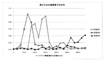
- an ionic liquid tributyl (2-methoxyethyl) phosphonium bis (trifluoromethanesulfonyl) in the film thickness (depth) direction from the hard coat layer surface (interface 40)
- the distribution of the ionic liquid was determined by measuring the concentration of sulfur atoms contained in the) imide).
- the optical film was cut so as to cover the sample table, and an analysis sample was prepared by attaching the optical film to the sample table via an adhesive sheet.
- the hard coat layer is etched while being ion-sputtered from the hard coat layer surface of the optical film (Ar + is irradiated, and a high-speed ion gun (Kaufman type ion gun) is used as the sputter ion gun). While exposing a specific depth from the surface, the exposed depth was gradually increased.
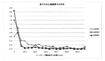
- Table 2 shows the measurement results of the optical films prepared in the above examples and comparative examples. Moreover, what plotted the measurement result of the optical film of the Example in FIG. 6 is shown in FIG. 6, and what graphed the measurement result of the optical film of the comparative example is shown in FIG.
- the solvent wiping-off property was evaluated as follows. First, the surface resistance value of the hard coat layer surface in the initial state before wiping with a solvent was measured using a trade name Hiresta (measurement limit 1.00 ⁇ 10 13 ⁇ ) manufactured by Mitsubishi Chemical Corporation. Next, the same part on the surface of the hard coat layer was wiped 10 times using a waste cloth (trade name Bencot Lint Free, manufactured by Asahi Kasei Co., Ltd.) soaked with the same amount of water, ethanol and MIBK, and then dried waste cloth. And wiped 10 times. Thereafter, the surface resistance value was measured in the same manner as described above. Table 3 shows the measurement results.
- Example 1 From Table 2 and FIG. 6, in Example 1, the depth from the hard coat layer surface (interface 40) has a peak of sulfur atom concentration at 300 nm, whereas in Comparative Example 1, the depth is 33.3 nm. There is a peak of sulfur atom concentration. In addition, the half value width of the peak of Example 1 was 83 nm. Similarly, Example 2 has a sulfur atom concentration peak at a depth of 133.3 nm, while Comparative Example 2 has a sulfur atom concentration peak at a depth of 0 nm. In addition, the half width of the peak of Example 2 was 90 nm.
- Example 3 has a sulfur atom concentration peak at a depth of 666.7 nm, while Comparative Example 3 has a sulfur atom concentration peak at a depth of 0 nm.
- the half width of the peak of Example 3 was 60 nm. From this, it can be seen that in the optical film according to the present invention, the peak of the abundance of the ionic liquid exists at a position deeper than 50 nm from the interface 40 of the hard coat layer.
- the optical films obtained in the examples had the same surface resistance value as in the initial state even after wiping off the solvent.
- the wiping property with respect to the organic solvent of ethanol and MIBK was excellent.
- the surface resistance value after wiping with water increased by two digits. Further, there was no wiping resistance against organic solvents.
- the optical films obtained in Comparative Examples 2 and 3 did not have solvent wiping resistance for all of water, ethanol and MIBK.
- the optical film of the present invention can be used as it is for products requiring antistatic properties.
- an optical film that can simultaneously achieve antistatic properties and hard coat properties can be provided.
- an optical film having antistatic properties, hard coat properties, low reflection, and no interference fringes can be provided. For this reason, it can be used for a dust adhesion-preventing building material (such as a decorative sheet) or an overcoat on the surface of an optical disk.
Landscapes
- Physics & Mathematics (AREA)
- General Physics & Mathematics (AREA)
- Optics & Photonics (AREA)
- Surface Treatment Of Optical Elements (AREA)
- Laminated Bodies (AREA)
- Polarising Elements (AREA)
Priority Applications (3)
| Application Number | Priority Date | Filing Date | Title |
|---|---|---|---|
| CN201080057928.3A CN102713686B (zh) | 2009-12-28 | 2010-12-22 | 光学薄膜、光学薄膜的制造方法、偏振板、显示面板及显示器 |
| US13/517,112 US20120327511A1 (en) | 2009-12-28 | 2010-12-22 | Optical film, method of producing optical film, polarizing plate, display panel, and display |
| KR1020127016473A KR101392811B1 (ko) | 2009-12-28 | 2010-12-22 | 광학 필름, 광학 필름의 제조 방법, 편광판, 디스플레이 패널 및 디스플레이 |
Applications Claiming Priority (4)
| Application Number | Priority Date | Filing Date | Title |
|---|---|---|---|
| JP2009-298797 | 2009-12-28 | ||
| JP2009298797 | 2009-12-28 | ||
| JP2010-281788 | 2010-12-17 | ||
| JP2010281788A JP5685074B2 (ja) | 2009-12-28 | 2010-12-17 | 光学フィルム、光学フィルムの製造方法、偏光板、ディスプレイパネル及びディスプレイ |
Publications (1)
| Publication Number | Publication Date |
|---|---|
| WO2011081072A1 true WO2011081072A1 (ja) | 2011-07-07 |
Family
ID=44226479
Family Applications (1)
| Application Number | Title | Priority Date | Filing Date |
|---|---|---|---|
| PCT/JP2010/073178 Ceased WO2011081072A1 (ja) | 2009-12-28 | 2010-12-22 | 光学フィルム、光学フィルムの製造方法、偏光板、ディスプレイパネル及びディスプレイ |
Country Status (6)
| Country | Link |
|---|---|
| US (1) | US20120327511A1 (enExample) |
| JP (1) | JP5685074B2 (enExample) |
| KR (1) | KR101392811B1 (enExample) |
| CN (2) | CN104101915B (enExample) |
| TW (1) | TWI479179B (enExample) |
| WO (1) | WO2011081072A1 (enExample) |
Families Citing this family (9)
| Publication number | Priority date | Publication date | Assignee | Title |
|---|---|---|---|---|
| WO2014097647A1 (ja) * | 2012-12-21 | 2014-06-26 | 三井化学株式会社 | シート状エポキシ樹脂組成物、それを用いた有機elデバイスの製造方法、有機elデバイスおよび有機elディスプレイパネル |
| JP6194665B2 (ja) * | 2013-07-16 | 2017-09-13 | 凸版印刷株式会社 | ハードコート組成物および反射防止フィルム |
| JP5700591B2 (ja) * | 2013-07-31 | 2015-04-15 | 株式会社フジクラ | 色素増感太陽電池素子 |
| WO2015029623A1 (ja) * | 2013-08-27 | 2015-03-05 | リンテック株式会社 | ハードコート積層体およびその製造方法 |
| JP6181711B2 (ja) * | 2015-07-13 | 2017-08-16 | 住友化学株式会社 | 偏光子保護フィルムおよびこれを用いた偏光板 |
| JP6574731B2 (ja) | 2016-03-25 | 2019-09-11 | 富士フイルム株式会社 | 光学フィルム、偏光板、及び画像表示装置 |
| KR102031558B1 (ko) * | 2017-02-24 | 2019-10-14 | 동우 화인켐 주식회사 | 하드 코팅 필름 및 이를 포함하는 화상 표시 장치 |
| CN108089246A (zh) * | 2017-12-04 | 2018-05-29 | 张家港康得新光电材料有限公司 | 一种光学膜及触控屏及光学膜的制备方法 |
| JP7172102B2 (ja) * | 2018-04-03 | 2022-11-16 | トヨタ自動車株式会社 | 車両 |
Citations (5)
| Publication number | Priority date | Publication date | Assignee | Title |
|---|---|---|---|---|
| JP2008026492A (ja) * | 2006-07-19 | 2008-02-07 | Lintec Corp | 反射防止フィルム |
| JP2008191544A (ja) * | 2007-02-07 | 2008-08-21 | Konica Minolta Opto Inc | 反射防止フィルム、及びそれを用いた偏光板、表示装置 |
| JP2008233371A (ja) * | 2007-03-19 | 2008-10-02 | Hitachi Maxell Ltd | 反射防止フィルム |
| JP2008274266A (ja) * | 2007-04-02 | 2008-11-13 | Dainippon Printing Co Ltd | 帯電防止性(及びハードコート性)を実現できる組成物、単層体、部材又は積層体 |
| JP2009265658A (ja) * | 2008-04-03 | 2009-11-12 | Dainippon Printing Co Ltd | 光学フィルム、及びその製造方法 |
Family Cites Families (8)
| Publication number | Priority date | Publication date | Assignee | Title |
|---|---|---|---|---|
| TWI305587B (en) * | 2005-11-16 | 2009-01-21 | Daxon Technology Inc | Optical film and fabrication method thereof |
| CN101130661A (zh) * | 2006-08-24 | 2008-02-27 | 达信科技股份有限公司 | 抗静电涂布液组合物及高穿透率抗静电薄膜的制造 |
| JP2008146021A (ja) * | 2006-09-08 | 2008-06-26 | Fujifilm Corp | 光学フィルム |
| US8597780B2 (en) * | 2007-08-10 | 2013-12-03 | Dai Nippon Printing Co., Ltd. | Hard coat film |
| JP5583367B2 (ja) * | 2008-07-15 | 2014-09-03 | 日本合成化学工業株式会社 | 光学部材用粘着剤組成物および光学部材用粘着剤ならびにそれを用いて得られる粘着剤層付き光学部材 |
| JP2011072878A (ja) * | 2009-09-29 | 2011-04-14 | Dainippon Printing Co Ltd | 積層構造体の製造方法、積層構造体、光学用部材及び塗工膜の形成方法 |
| JP2011169987A (ja) * | 2010-02-16 | 2011-09-01 | Sony Corp | 防眩性フィルムおよびその製造方法、紫外線硬化型樹脂組成物、ならびに表示装置 |
| JP5842320B2 (ja) * | 2010-09-16 | 2016-01-13 | 大日本印刷株式会社 | 光学フィルムの製造方法、光学フィルム、偏光板及び画像表示装置 |
-
2010
- 2010-12-17 JP JP2010281788A patent/JP5685074B2/ja active Active
- 2010-12-22 WO PCT/JP2010/073178 patent/WO2011081072A1/ja not_active Ceased
- 2010-12-22 US US13/517,112 patent/US20120327511A1/en not_active Abandoned
- 2010-12-22 CN CN201410299390.7A patent/CN104101915B/zh not_active Expired - Fee Related
- 2010-12-22 CN CN201080057928.3A patent/CN102713686B/zh active Active
- 2010-12-22 KR KR1020127016473A patent/KR101392811B1/ko active Active
- 2010-12-27 TW TW099146065A patent/TWI479179B/zh active
Patent Citations (5)
| Publication number | Priority date | Publication date | Assignee | Title |
|---|---|---|---|---|
| JP2008026492A (ja) * | 2006-07-19 | 2008-02-07 | Lintec Corp | 反射防止フィルム |
| JP2008191544A (ja) * | 2007-02-07 | 2008-08-21 | Konica Minolta Opto Inc | 反射防止フィルム、及びそれを用いた偏光板、表示装置 |
| JP2008233371A (ja) * | 2007-03-19 | 2008-10-02 | Hitachi Maxell Ltd | 反射防止フィルム |
| JP2008274266A (ja) * | 2007-04-02 | 2008-11-13 | Dainippon Printing Co Ltd | 帯電防止性(及びハードコート性)を実現できる組成物、単層体、部材又は積層体 |
| JP2009265658A (ja) * | 2008-04-03 | 2009-11-12 | Dainippon Printing Co Ltd | 光学フィルム、及びその製造方法 |
Also Published As
| Publication number | Publication date |
|---|---|
| KR20120102093A (ko) | 2012-09-17 |
| CN104101915B (zh) | 2016-01-06 |
| TWI479179B (zh) | 2015-04-01 |
| KR101392811B1 (ko) | 2014-05-09 |
| TW201137383A (en) | 2011-11-01 |
| CN102713686B (zh) | 2014-11-05 |
| JP2011154352A (ja) | 2011-08-11 |
| CN102713686A (zh) | 2012-10-03 |
| US20120327511A1 (en) | 2012-12-27 |
| CN104101915A (zh) | 2014-10-15 |
| JP5685074B2 (ja) | 2015-03-18 |
Similar Documents
| Publication | Publication Date | Title |
|---|---|---|
| JP5685074B2 (ja) | 光学フィルム、光学フィルムの製造方法、偏光板、ディスプレイパネル及びディスプレイ | |
| JP5359137B2 (ja) | 光学積層体、その製造方法、偏光板及び画像表示装置 | |
| KR101811913B1 (ko) | 광학 적층체의 제조 방법 | |
| JP5779863B2 (ja) | 光学フィルムの製造方法、光学フィルム、偏光板及びディスプレイ | |
| KR101928586B1 (ko) | 대전 방지성 하드 코트 필름, 그 제조 방법, 편광판 및 화상 표시 장치 | |
| JP2018097387A (ja) | ハードコートフィルム、偏光板及び画像表示装置 | |
| JP7102042B2 (ja) | 反射防止フィルム、偏光板およびディスプレイ装置 | |
| JP2016014889A (ja) | ハードコートフィルム、偏光板、及び画像表示装置 | |
| KR20180082631A (ko) | 광학 적층체, 편광판 및 화상 표시 장치 | |
| KR101811899B1 (ko) | 광학 적층체, 편광판 및 화상 표시 장치 | |
| JP4983792B2 (ja) | 光学積層体 | |
| JP2009069428A (ja) | 光学積層体の製造方法、光学積層体、偏光板及び画像表示装置 | |
| KR101943659B1 (ko) | 광학 필름, 화상 표시 장치 및 화상 표시 장치의 제조 방법 | |
| KR20130054314A (ko) | 대전 방지층용 경화성 수지 조성물, 광학 필름, 편광판 및 디스플레이 패널 | |
| KR20160037117A (ko) | 광학 필름 및 그것을 구비한 편광판, 액정 표시 장치, 및 광학 필름의 제조 방법 | |
| JP6401745B2 (ja) | 光学フィルム、偏光板及びディスプレイの帯電防止方法 | |
| US11644604B2 (en) | Optical film, polarizing plate, and image display device | |
| US20050233069A1 (en) | Antiglare film | |
| KR102337211B1 (ko) | 반사 방지 필름, 편광판 및 디스플레이 장치 | |
| KR20130026269A (ko) | 하드코팅 필름, 이를 포함하는 편광판 및 표시 장치 | |
| JP2016170467A (ja) | タッチパネル用透明導電性フィルムのベースフィルムおよびタッチパネル用透明導電性フィルム | |
| KR20240131909A (ko) | 광학 필름의 제조 방법, 광학 필름, 광학 부재의 제조 방법, 화상 표시 장치의 제조 방법, 광학 부재, 및 화상 표시 장치 | |
| JP6131733B2 (ja) | 光学フィルムの製造方法および光学フィルム | |
| JP4811748B2 (ja) | ハードコート層の滑り性を改善したディスプレイ用積層体の製造方法 |
Legal Events
| Date | Code | Title | Description |
|---|---|---|---|
| WWE | Wipo information: entry into national phase |
Ref document number: 201080057928.3 Country of ref document: CN |
|
| 121 | Ep: the epo has been informed by wipo that ep was designated in this application |
Ref document number: 10840929 Country of ref document: EP Kind code of ref document: A1 |
|
| ENP | Entry into the national phase |
Ref document number: 20127016473 Country of ref document: KR Kind code of ref document: A |
|
| NENP | Non-entry into the national phase |
Ref country code: DE |
|
| WWE | Wipo information: entry into national phase |
Ref document number: 13517112 Country of ref document: US |
|
| 122 | Ep: pct application non-entry in european phase |
Ref document number: 10840929 Country of ref document: EP Kind code of ref document: A1 |