WO2011078618A2 - 주행모드를 고려한 급전 및 집전 기반 시설 구축 방법 - Google Patents
주행모드를 고려한 급전 및 집전 기반 시설 구축 방법 Download PDFInfo
- Publication number
- WO2011078618A2 WO2011078618A2 PCT/KR2010/009313 KR2010009313W WO2011078618A2 WO 2011078618 A2 WO2011078618 A2 WO 2011078618A2 KR 2010009313 W KR2010009313 W KR 2010009313W WO 2011078618 A2 WO2011078618 A2 WO 2011078618A2
- Authority
- WO
- WIPO (PCT)
- Prior art keywords
- power supply
- power
- section
- supply device
- cost
- Prior art date
- Legal status (The legal status is an assumption and is not a legal conclusion. Google has not performed a legal analysis and makes no representation as to the accuracy of the status listed.)
- Ceased
Links
Images


Classifications
-
- B—PERFORMING OPERATIONS; TRANSPORTING
- B60—VEHICLES IN GENERAL
- B60L—PROPULSION OF ELECTRICALLY-PROPELLED VEHICLES; SUPPLYING ELECTRIC POWER FOR AUXILIARY EQUIPMENT OF ELECTRICALLY-PROPELLED VEHICLES; ELECTRODYNAMIC BRAKE SYSTEMS FOR VEHICLES IN GENERAL; MAGNETIC SUSPENSION OR LEVITATION FOR VEHICLES; MONITORING OPERATING VARIABLES OF ELECTRICALLY-PROPELLED VEHICLES; ELECTRIC SAFETY DEVICES FOR ELECTRICALLY-PROPELLED VEHICLES
- B60L53/00—Methods of charging batteries, specially adapted for electric vehicles; Charging stations or on-board charging equipment therefor; Exchange of energy storage elements in electric vehicles
- B60L53/10—Methods of charging batteries, specially adapted for electric vehicles; Charging stations or on-board charging equipment therefor; Exchange of energy storage elements in electric vehicles characterised by the energy transfer between the charging station and the vehicle
- B60L53/12—Inductive energy transfer
-
- B—PERFORMING OPERATIONS; TRANSPORTING
- B60—VEHICLES IN GENERAL
- B60L—PROPULSION OF ELECTRICALLY-PROPELLED VEHICLES; SUPPLYING ELECTRIC POWER FOR AUXILIARY EQUIPMENT OF ELECTRICALLY-PROPELLED VEHICLES; ELECTRODYNAMIC BRAKE SYSTEMS FOR VEHICLES IN GENERAL; MAGNETIC SUSPENSION OR LEVITATION FOR VEHICLES; MONITORING OPERATING VARIABLES OF ELECTRICALLY-PROPELLED VEHICLES; ELECTRIC SAFETY DEVICES FOR ELECTRICALLY-PROPELLED VEHICLES
- B60L53/00—Methods of charging batteries, specially adapted for electric vehicles; Charging stations or on-board charging equipment therefor; Exchange of energy storage elements in electric vehicles
- B60L53/30—Constructional details of charging stations
- B60L53/35—Means for automatic or assisted adjustment of the relative position of charging devices and vehicles
- B60L53/38—Means for automatic or assisted adjustment of the relative position of charging devices and vehicles specially adapted for charging by inductive energy transfer
-
- B—PERFORMING OPERATIONS; TRANSPORTING
- B60—VEHICLES IN GENERAL
- B60L—PROPULSION OF ELECTRICALLY-PROPELLED VEHICLES; SUPPLYING ELECTRIC POWER FOR AUXILIARY EQUIPMENT OF ELECTRICALLY-PROPELLED VEHICLES; ELECTRODYNAMIC BRAKE SYSTEMS FOR VEHICLES IN GENERAL; MAGNETIC SUSPENSION OR LEVITATION FOR VEHICLES; MONITORING OPERATING VARIABLES OF ELECTRICALLY-PROPELLED VEHICLES; ELECTRIC SAFETY DEVICES FOR ELECTRICALLY-PROPELLED VEHICLES
- B60L53/00—Methods of charging batteries, specially adapted for electric vehicles; Charging stations or on-board charging equipment therefor; Exchange of energy storage elements in electric vehicles
- B60L53/60—Monitoring or controlling charging stations
- B60L53/66—Data transfer between charging stations and vehicles
- B60L53/665—Methods related to measuring, billing or payment
-
- H—ELECTRICITY
- H02—GENERATION; CONVERSION OR DISTRIBUTION OF ELECTRIC POWER
- H02J—ELECTRIC POWER NETWORKS; CIRCUIT ARRANGEMENTS OR SYSTEMS FOR SUPPLYING OR DISTRIBUTING ELECTRIC POWER; SYSTEMS FOR STORING ELECTRIC ENERGY
- H02J50/00—Circuit arrangements or systems for wireless supply or distribution of electric power
- H02J50/10—Circuit arrangements or systems for wireless supply or distribution of electric power using inductive coupling
-
- H—ELECTRICITY
- H02—GENERATION; CONVERSION OR DISTRIBUTION OF ELECTRIC POWER
- H02J—ELECTRIC POWER NETWORKS; CIRCUIT ARRANGEMENTS OR SYSTEMS FOR SUPPLYING OR DISTRIBUTING ELECTRIC POWER; SYSTEMS FOR STORING ELECTRIC ENERGY
- H02J50/00—Circuit arrangements or systems for wireless supply or distribution of electric power
- H02J50/40—Circuit arrangements or systems for wireless supply or distribution of electric power using two or more transmitting or receiving devices
-
- B—PERFORMING OPERATIONS; TRANSPORTING
- B60—VEHICLES IN GENERAL
- B60Y—INDEXING SCHEME RELATING TO ASPECTS CROSS-CUTTING VEHICLE TECHNOLOGY
- B60Y2200/00—Type of vehicle
- B60Y2200/90—Vehicles comprising electric prime movers
- B60Y2200/91—Electric vehicles
-
- Y—GENERAL TAGGING OF NEW TECHNOLOGICAL DEVELOPMENTS; GENERAL TAGGING OF CROSS-SECTIONAL TECHNOLOGIES SPANNING OVER SEVERAL SECTIONS OF THE IPC; TECHNICAL SUBJECTS COVERED BY FORMER USPC CROSS-REFERENCE ART COLLECTIONS [XRACs] AND DIGESTS
- Y02—TECHNOLOGIES OR APPLICATIONS FOR MITIGATION OR ADAPTATION AGAINST CLIMATE CHANGE
- Y02T—CLIMATE CHANGE MITIGATION TECHNOLOGIES RELATED TO TRANSPORTATION
- Y02T10/00—Road transport of goods or passengers
- Y02T10/60—Other road transportation technologies with climate change mitigation effect
- Y02T10/70—Energy storage systems for electromobility, e.g. batteries
-
- Y—GENERAL TAGGING OF NEW TECHNOLOGICAL DEVELOPMENTS; GENERAL TAGGING OF CROSS-SECTIONAL TECHNOLOGIES SPANNING OVER SEVERAL SECTIONS OF THE IPC; TECHNICAL SUBJECTS COVERED BY FORMER USPC CROSS-REFERENCE ART COLLECTIONS [XRACs] AND DIGESTS
- Y02—TECHNOLOGIES OR APPLICATIONS FOR MITIGATION OR ADAPTATION AGAINST CLIMATE CHANGE
- Y02T—CLIMATE CHANGE MITIGATION TECHNOLOGIES RELATED TO TRANSPORTATION
- Y02T10/00—Road transport of goods or passengers
- Y02T10/60—Other road transportation technologies with climate change mitigation effect
- Y02T10/7072—Electromobility specific charging systems or methods for batteries, ultracapacitors, supercapacitors or double-layer capacitors
-
- Y—GENERAL TAGGING OF NEW TECHNOLOGICAL DEVELOPMENTS; GENERAL TAGGING OF CROSS-SECTIONAL TECHNOLOGIES SPANNING OVER SEVERAL SECTIONS OF THE IPC; TECHNICAL SUBJECTS COVERED BY FORMER USPC CROSS-REFERENCE ART COLLECTIONS [XRACs] AND DIGESTS
- Y02—TECHNOLOGIES OR APPLICATIONS FOR MITIGATION OR ADAPTATION AGAINST CLIMATE CHANGE
- Y02T—CLIMATE CHANGE MITIGATION TECHNOLOGIES RELATED TO TRANSPORTATION
- Y02T90/00—Enabling technologies or technologies with a potential or indirect contribution to GHG emissions mitigation
- Y02T90/10—Technologies relating to charging of electric vehicles
- Y02T90/12—Electric charging stations
-
- Y—GENERAL TAGGING OF NEW TECHNOLOGICAL DEVELOPMENTS; GENERAL TAGGING OF CROSS-SECTIONAL TECHNOLOGIES SPANNING OVER SEVERAL SECTIONS OF THE IPC; TECHNICAL SUBJECTS COVERED BY FORMER USPC CROSS-REFERENCE ART COLLECTIONS [XRACs] AND DIGESTS
- Y02—TECHNOLOGIES OR APPLICATIONS FOR MITIGATION OR ADAPTATION AGAINST CLIMATE CHANGE
- Y02T—CLIMATE CHANGE MITIGATION TECHNOLOGIES RELATED TO TRANSPORTATION
- Y02T90/00—Enabling technologies or technologies with a potential or indirect contribution to GHG emissions mitigation
- Y02T90/10—Technologies relating to charging of electric vehicles
- Y02T90/14—Plug-in electric vehicles
Definitions
- the present invention relates to the construction of a charging system for an electric vehicle, and in particular, a driving mode that enables the most efficient power supply and current collecting infrastructure to be constructed in consideration of economic aspects such as a road supply device installation cost and electric energy cost.
- the present invention relates to a power supply and current collection infrastructure construction method.
- An electric vehicle means a vehicle that operates by using electricity as a power source. Electric vehicles are equipped with a battery that can be charged as a power source in the vehicle itself, and operates using the power supplied from the mounted battery.
- An electric vehicle is largely composed of a drive motor for driving an electric vehicle driven by electricity and a battery for supplying electricity to the drive motor.
- the battery of an electric vehicle takes a long time to charge, and the distance driven by a single charge is limited. Therefore, the electric vehicle must be frequently charged to secure the intended travel distance, so the installation of the charging station and the charging system are very important problems in the operation of the electric vehicle.
- Non-contact magnetic induction charging has been researched and commercialized as a charging method for new electric vehicles.
- the current collector of an electric vehicle adopts the principle of a transistor that converts a magnetic field force generated from a power supply device (feed rail) embedded in a road into electrical energy.
- the feed rail which generates a magnetic field for charging an electric vehicle by a non-contact magnetic induction charging method, supplies electric energy and has a feed line surrounded by an insulation duct and a ferrite installed to prevent leakage of magnetic flux on the lower side of the feed line. It includes a core module.
- a power transmission system of a vehicle that is driven and powered by a roadway includes a power conditioner, a roadway power supply device, and a vehicle current collector.
- the present invention provides a method for constructing a power supply and current collection infrastructure in consideration of a driving mode to enable the most efficient power supply and current collection infrastructure in consideration of economic aspects such as a road supply device installation cost and electric energy cost. Its purpose is to.
- the present invention provides a power supply and current collection infrastructure construction method considering the driving mode to minimize the construction cost through a wider economic analysis in consideration of the system operation period, future electric energy cost change trend, system management cost, etc. Its purpose is to.
- An object of the present invention is to provide a method for building a power supply and current collection infrastructure that can minimize the electric energy cost of operating the system by building in consideration of the driving mode in the power supply and current collection infrastructure construction stage. have.
- the present invention provides a power supply device that delivers high power at a high load point in consideration of a running load and a power feeding time, and considers a driving mode in which a sufficient charging time can be secured by driving at a low speed in a feeding section while receiving high power. Its purpose is to provide a method for building power supply and current collection infrastructure.
- a method for constructing a power supply and current collecting infrastructure in consideration of a driving mode selecting a candidate device for installing a power supply device in an entire operation scheduled section; Calculating a running load, a power feeding time, and a power transmission amount for each of the selected candidate sections; Comparing the calculated power transfer amount of the candidate section with a reference value; Comparing the charging time to be secured at low speed in the candidate section with the reference time when the calculated power transfer amount of the candidate section is greater than the reference value; And determining the fitness level based on the electric energy cost and the power supply device installation cost in the section satisfying the criterion.
- Such a power supply and current collection infrastructure construction method considering the driving mode according to the present invention has the following effects.
- FIG. 1 is a block diagram showing the concept of a power supply and current collection infrastructure construction method considering the driving mode according to the present invention
- Figure 2 is a flow chart showing the considerations in the construction of power supply and current collection infrastructure considering the driving mode according to the present invention
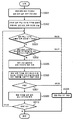
- FIG. 3 is a flowchart for a method for establishing a power supply and current collection infrastructure considering a driving mode according to the present invention
- FIG. 1 is a block diagram showing the concept of a power supply and current collection infrastructure construction method considering the driving mode according to the present invention.
- the present invention relates to the construction of a charging infrastructure for minimizing the number and length of driveway power supply devices that take the most cost when constructing an on-line electric power bus operation system and the system operation cost in consideration of electric energy consumption.
- the power supply device installation section 100 is selected in consideration of the running load, the power feeding time, and the power transmission amount.
- the power delivered from the feeder at the high load point in the driving profile directly drives the motor, thereby reducing the total loss between the feeder and the motor, thereby increasing power transfer efficiency.
- the section 110 that does not have a power supply device is driven using a battery, and in order to complete the driving profile including the section, the state of charge before and after driving must be kept constant.
- the state of charge before and after driving must be kept constant.
- a method for constructing a power supply and current collection infrastructure considering a driving mode is largely selected as a candidate section for installing a power supply device, calculating a running load, a feeding time, and a power transmission amount of the selected candidate section, and comparing them with a reference value, and a comparison standard Comprising the step of satisfying the electric energy cost, the step of determining the suitability based on the weight according to the power supply device installation cost minimization.
- FIG. 2 is a flowchart illustrating considerations when constructing a power supply and current collection infrastructure considering a driving mode according to the present invention
- FIG. 3 is a flowchart for a method of constructing a power supply and current collection infrastructure considering a driving mode according to the present invention.
- a candidate device for installing the power feeding device is selected in the entire scheduled operation period.
- the driving load, the power feeding time, and the power delivery amount are calculated for each of the selected candidate sections.
- the calculated power transfer amount of the candidate section is compared with a reference value (S303).
- the corresponding section is excluded from the candidate section (S308).
- the charging time that can be secured by the low-speed operation in the candidate section is compared with the reference time.
- the corresponding section is preliminarily designated as the power supply device installation section.
- the preliminary designation section determines the suitability based on the weight according to minimizing the electric energy cost and minimizing the power supply device installation (S306).
- the corresponding section is determined to be a power supply device installation section, and if it does not meet the criterion, the corresponding section is excluded from the candidate section (S308).
- the determination table for determining the fitness is made in advance, and factors such as the number of passengers who cannot be adjusted and the traffic situation are excluded.
- Table 1 shows an example of the determination table for determining the goodness of fit, it is natural that the goodness of rank, items may vary.
- Table 1 Fit Minimize your electrical energy costs Minimizing Feeder Equipment Costs One Hill Climbing Section, High Speed Driving Section station 2 Low speed segment Hill Climbing Area, Time Lapse 3 Intersection and traffic lights Intersection and traffic lights 4 station A high speed segment
- the present invention provides a power supply device for delivering high power at a high load point (first element), and secures sufficient charging time by driving at a low speed in a power supply section while receiving high power (second element).
- the long time charging time securing method through the low speed feeding section is a method of increasing the total amount of electric energy to be fed, so that a large number of electric energy can be delivered to a small number of feeding devices, thereby reducing the initial feeding device installation cost.
- the power supply and current collection infrastructure construction method considering the driving mode according to the present invention provides the most efficient power supply and current collection infrastructure in consideration of economic aspects such as a road supply device installation cost and electric energy cost. Make it possible to build.
Landscapes
- Engineering & Computer Science (AREA)
- Power Engineering (AREA)
- Transportation (AREA)
- Mechanical Engineering (AREA)
- Computer Networks & Wireless Communication (AREA)
- Charge And Discharge Circuits For Batteries Or The Like (AREA)
- Electric Propulsion And Braking For Vehicles (AREA)
Abstract
본 발명은 차도 급전 장치 설치 비용, 전기 에너지 비용 등의 경제적 측면을 고려하여 가장 효율적인 급전 및 집전 기반시설(infrastructure)을 구축하는 것이 가능하도록 한 주행모드를 고려한 급전 및 집전 기반 시설 구축 방법에 관한 것으로, 전체 운행 예정 구간에서 급전 장치 설치 후보 구간을 선정하는 단계; 선정된 모든 후보 구간의 각각에 대하여 주행 부하, 급전 시간, 전력 전달량을 산출하는 단계; 해당 후보 구간의 산출된 전력 전달량을 기준값과 비교하는 단계; 해당 후보 구간의 산출된 전력 전달량이 기준값보다 크면 해당 후보구간에서 저속 운행으로 확보할 수 있는 충전 시간을 기준 시간과 비교하는 단계; 상기 기준을 만족하는 구간을, 전기 에너지 비용, 급전 장치 설치 비용을 기준으로 적합도를 판정하여 집전 장치 설치구간을 확정하는 단계;를 포함하는 것을 특징으로 한다.
Description
본 발명은 전기자동차의 충전 시스템 구축에 관한 것으로, 구체적으로 차도 급전 장치 설치 비용, 전기 에너지 비용 등의 경제적 측면을 고려하여 가장 효율적인 급전 및 집전 기반시설(infrastructure)을 구축하는 것이 가능하도록 한 주행모드를 고려한 급전 및 집전 기반 시설 구축 방법에 관한 것이다.
현재, 자동차에서 배출되는 배기가스가 환경 오염의 주요 원인이 되고 있는 문제를 해결하기 위하여, 자동차 제조 업계에서는 배출가스를 줄일 수 있는 자동차의 개발이 진행되고 있고, 더 나아가 배출가스를 발생하지 않는 전기 자동차의 상용화가 부분적으로 시도되고 있다.
전기차량은 전기를 전력공급원으로 하여 운행하는 차량을 의미한다. 전기자동차는 차량 자체에 전력공급원으로 충전이 가능한 배터리를 탑재하고, 탑재된 배터리에서 공급되는 전력을 이용하여 운행한다.
전기자동차는 크게 전기에 의해 구동되어 전기 자동차를 운행시키기 위한 구동 모터와, 그 구동 모터에 전기를 공급하는 배터리로 구성된다.
전기자동차의 배터리는 충전시간이 오래 걸리며, 또한 한번 충전에 의해 주행하는 거리가 제한적이다. 따라서 전기자동차는 목적한 이동거리를 확보하기 위해서는 자주 충전을 해주어야만 하므로, 전기차량의 운행에 있어서 충전소의 설치 및 충전시스템은 아주 중요한 문제이다.
새로운 전기자동차의 충전 방식으로 비접촉 자기 유도 충전 방식이 연구 개발되어 상용화 단계에 있다.
비접촉 자기 유도 충전 방식으로 전기자동차의 집전장치는 도로에 매설된 급전장치(급전레일)에서 발생하는 자기장의 힘을 전기에너지로 변환하여 받는 트랜지스터의 원리가 적용된다.
비접촉 자기 유도 충전 방식으로 전기자동차의 충전을 위한 자기장을 발생시키는 급전레일은 전기에너지를 공급하며 외면이 절연덕트로 둘러싸인 급전라인과, 상기 급전라인의 하부측에 자속의 누설을 방지하도록 설치되는 페라이트코어 모듈을 포함한다.
차도에서 전력을 공급받아 주행하는 차량의 동력 전달 시스템은 전력 배분 장치(Power Conditioner), 차도 급전 장치, 차량 집전 장치로 구성된다.
이와 같은 동력 전달 시스템을 구축하기 위해서는 차도 급전 장치 설치 비용, 전기 에너지 비용 등의 경제적 측면을 고려하여 가장 효율적인 급전 및 집전 기반시설(infrastructure)을 구축하는 것이 필요하다.
본 발명은 차도 급전 장치 설치 비용, 전기 에너지 비용 등의 경제적 측면을 고려하여 가장 효율적인 급전 및 집전 기반시설(infrastructure)을 구축하는 것이 가능하도록 한 주행모드를 고려한 급전 및 집전 기반 시설 구축 방법을 제공하는 데 그 목적이 있다.
본 발명은 시스템 운영 기간, 향후 전기 에너지 비용 변화 경향, 시스템 관리 비용 등을 고려하여 보다 폭넓은 경제성 분석을 통해 구축 비용을 최소화할 수 있도록 한 주행모드를 고려한 급전 및 집전 기반 시설 구축 방법을 제공하는 데 그 목적이 있다.
본 발명은 급전 및 집전 기반 시설 구축 단계에서 주행 모드를 고려하여 구축을 하는 것에 의해 시스템 운영시에 소요되는 전기 에너지 비용을 최소화할 수 있도록 한 급전 및 집전 기반 시설 구축 방법을 제공하는 데 그 목적이 있다.
본 발명은 주행 부하, 급전 시간을 고려하여 고 부하 지점에서 고 전력을 전달하는 급전 장치를 설치하고, 고 전력을 전달받으면서 급전 구간을 저속 운행하여 충분한 충전시간을 확보할 수 있도록 한 주행모드를 고려한 급전 및 집전 기반 시설 구축 방법을 제공하는 데 그 목적이 있다.
이와 같은 목적을 달성하기 위한 본 발명에 따른 주행모드를 고려한 급전 및 집전 기반 시설 구축 방법은 전체 운행 예정 구간에서 급전 장치 설치 후보 구간을 선정하는 단계; 선정된 모든 후보 구간의 각각에 대하여 주행 부하, 급전 시간, 전력 전달량을 산출하는 단계; 해당 후보 구간의 산출된 전력 전달량을 기준값과 비교하는 단계; 해당 후보 구간의 산출된 전력 전달량이 기준값보다 크면 해당 후보구간에서 저속 운행으로 확보할 수 있는 충전 시간을 기준 시간과 비교하는 단계; 상기 기준을 만족하는 구간을, 전기 에너지 비용, 급전 장치 설치 비용을 기준으로 적합도를 판정하여 집전 장치 설치구간을 확정하는 단계;를 포함하는 것을 특징으로 한다.
이와 같은 본 발명에 따른 주행모드를 고려한 급전 및 집전 기반 시설 구축 방법은 다음과 같은 효과를 갖는다.
첫째, 급전 및 집전 기반 시설 구축 단계에서 주행 모드를 고려하여 구축을 하는 것에 의해 시스템 운영시에 소요되는 전기 에너지 비용을 최소화할 수 있다.
둘째, 고 부하 지점에서 고 전력을 전달하는 급전 장치를 설치하고, 고 전력을 전달받으면서 급전 구간을 저속 운행하여 충분한 충전시간을 확보할 수 있도록 한다.
셋째, 차도 급전 장치 설치 비용, 전기 에너지 비용 등의 경제적 측면을 고려하여 가장 효율적인 급전 및 집전 기반시설(infrastructure)을 구축하는 것이 가능하다.
따라서, 전기 에너지 비용 변화 경향, 시스템 관리 비용을 최소화할 수 있다.
도 1은 본 발명에 따른 주행모드를 고려한 급전 및 집전 기반 시설 구축 방법의 개념을 나타낸 구성도
도 2는 본 발명에 따른 주행모드를 고려한 급전 및 집전 기반 시설 구축시의 고려 사항을 나타낸 흐름도
도 3은 본 발명에 따른 주행모드를 고려한 급전 및 집전 기반 시설 구축 방법을 위한 플로우차트
이하, 본 발명에 따른 주행모드를 고려한 급전 및 집전 기반 시설 구축 방법의 바람직한 실시예에 관하여 상세히 설명하면 다음과 같다.
본 발명에 따른 주행모드를 고려한 급전 및 집전 기반 시설 구축 방법의 특징 및 이점들은 이하에서의 각 실시예에 대한 상세한 설명을 통해 명백해질 것이다.
도 1은 본 발명에 따른 주행모드를 고려한 급전 및 집전 기반 시설 구축 방법의 개념을 나타낸 구성도이다.
본 발명은 온라인 전기 동력 버스 운행 시스템 구축 시 가장 많은 비용을 차지하는 차도 급전장치의 개수 및 길이와, 전기 에너지 사용량을 고려한 시스템 운용 비용을 최소화하기 위한 충전 기반시설 구축에 관한 것이다.
이를 위하여 본 발명에서는 주행 부하, 급전 시간, 전력 전달량을 고려하여 급전 장치 설치 구간(100)을 선정한다.
급전 장치의 설치 구간 및 급전 상황에 대하여 온라인 전기 동력 버스 운행시 효율적인 에너지 사용을 위한 분석을 하면, 전력 전달 시스템 구축을 위해 아래와 같은 두 가지 요소를 고려하는 것이 필요하다.
첫째, 차도 급전장치 - 동력 장치 (모터) 간 전력 전달 효율, 둘째, 최소 길이 및 개수로 효율적인 운행이 가능한 급전장치 설치이다.
급전장치 - 집전장치 간 전력 전달은 고전력 전달시 높은 효율을 보인다는 것이 선행 연구(Berkeley PATH Project)를 통해 알려지고 있다.
급전 장치 - 모터 간 전력 전달 효율을 높이기 위해서는 직접 급전장치에서 전력을 전달 받아 모터를 구동함으로써 배터리 충/방전 효율과 관련된 전력 손실을 줄이는 것이 필요하다.
따라서 주행 프로파일상 고부하 지점에서 급전 장치에서 전달되는 전력이 직접 모터를 구동시킴으로써 급전 장치 - 모터 간 총 손실을 줄여 전력 전달 효율을 높일 수 있다.
그리고 급전장치를 설치하지 않은 구간(110)은 배터리를 사용하여 주행하는데, 이 구간을 포함한 운행 프로파일을 완주하기 위해 주행 전후 배터리 충전 상태량( State Of Charge)을 일정하게 유지해야 하는데, 최소 길이의 급전 장치로서 배터리 충전 상태량을 일정하게 유지하도록 충전하기 위해 급전 시 높은 전력을 전달하거나 급전 구간(100)에서의 충전 시간을 충분히 확보해야 한다.
최대 100kw 공급 전력으로 버스 집전 장치에 60kw 전력을 전달하는 실험에서 보면, 최대 공급 전력 한계를 고려했을 때 급전 구간에서의 충분한 충전 시간 확보가 조정 가능한 요소가 될 것이다.
본 발명에 따른 주행모드를 고려한 급전 및 집전 기반 시설 구축 방법은 크게 급전 장치 설치 후보 구간을 선정하고 선정된 후보 구간의 주행 부하, 급전 시간, 전력 전달량 산출을 하여 기준값과 비교하는 단계와, 비교 기준을 만족하는 구간을 전기 에너지 비용 최소화, 급전 장치 설치 비용 최소화에 따른 가중치를 기준으로 적합도를 판정하는 단계를 포함한다.
도 2는 본 발명에 따른 주행모드를 고려한 급전 및 집전 기반 시설 구축시의 고려 사항을 나타낸 흐름도이고, 도 3은 본 발명에 따른 주행모드를 고려한 급전 및 집전 기반 시설 구축 방법을 위한 플로우차트이다.
본 발명에 따른 주행모드를 고려한 급전 및 집전 기반 시설 구축 방법은 먼저, 전체 운행 예정 구간에서 급전 장치 설치 후보 구간을 선정한다.(S301)
이어, 선정된 모든 후보 구간의 각각에 대하여 주행 부하, 급전 시간, 전력 전달량 산출을 한다.(S302)
그리고 해당 후보 구간의 산출된 전력 전달량을 기준값과 비교한다.(S303)
해당 후보 구간의 산출된 전력 전달량이 기준값보다 작으면 해당 구간을 후보 구간에서 제외한다.(S308)
그리고 해당 후보 구간의 산출된 전력 전달량이 기준값보다 크면 해당 후보구간에서 저속 운행으로 확보할 수 있는 충전 시간을 기준 시간과 비교한다.(S304)
비교 결과 충전 가능 시간이 더 작으면 해당 구간을 후보 구간에서 제외한다.(S308)
그리고 비교 결과 충전 가능 시간이 더 크면 해당 구간을 급전 장치 설치 구간으로 예비 지정한다.(S305)
예비 지정 구간을 전기 에너지 비용 최소화, 급전 장치 설치 비용 최소화에 따른 가중치를 기준으로 적합도를 판정한다.(S306)
상기 판정에서 적합도가 미리 설정한 기준인 경우에는(S307), 해당 구간을 급전 장치 설치 구간으로 확정하고, 기준에 미달하는 경우에는 해당 구간을 후보 구간에서 제외한다.(S308)
이와 같은 과정을 전체 구간에 대하여 반복하여(S310), 전체 운행 구간에 대한 집전 장치 설치구간을 확정한다.
여기서, 상기 적합도 판정을 위한 판정 테이블은 미리 만들어지는 것으로 조정이 불가능한 승차 인원수,교통 상황 등의 요인은 배제한다.
표 1은 적합도 판정을 위한 판정 테이블의 일예를 나타낸 것으로, 적합도 순위, 항목이 달라질 수 있음은 당연하다.
표 1
| 적합순위 | 전기 에너지 비용 최소화 | 급전 장치 설비 비용 최소화 |
| 1 | 언덕 오르막구간, 고속 주행구간 | 정류장 |
| 2 | 저속 주행 구간 | 언덕 오르막구간, 저속 주행 구간 |
| 3 | 교차로 및 신호등 | 교차로 및 신호등 |
| 4 | 정류장 | 고속 주행 구간 |
이상에서와 같이 본 발명은 (제1요소) 고 부하 지점에서 고 전력을 전달하는 급전 장치를 설치하고, (제2요소) 고 전력을 전달받으면서 급전 구간을 저속 운행하여 충분한 충전시간을 확보할 수 있도록 하는 것이다.
급전 기반 설비를 운영하기 위한 비용으로서 상기 두 가지 요소는 각각 시스템 운영 시 전기 에너지 비용, 초기 설치 비용을 감소시키는 중요한 요인이다.
고 부하 지점에서 고 전력을 전달하는 경우 시스템에서 손실되는 전기에너지를 최소화시켜 시스템 효율을 높이는 경우로서, 장기간 시스템 운영 시 큰 경제적 효과를 기대할 수 있다.
급전 구간 저속 운행을 통한 장시간 충전시간 확보 방안은 급전되는 전기에너지 총량을 늘리는 방법으로서 적은 개수의 급전 장치로 많은 전기 에너지를 전달할 수 있어 초기 급전 장치 설치 비용을 줄일 수 있다.
이상에서의 설명에서와 같이 본 발명에 따른 주행모드를 고려한 급전 및 집전 기반 시설 구축 방법은 차도 급전 장치 설치 비용, 전기 에너지 비용 등의 경제적 측면을 고려하여 가장 효율적인 급전 및 집전 기반시설(infrastructure)을 구축하는 것이 가능하도록 한다.
이상에서의 설명에서와 같이 본 발명의 본질적인 특성에서 벗어나지 않는 범위에서 변형된 형태로 본 발명이 구현되어 있음을 이해할 수 있을 것이다.
그러므로 명시된 실시 예들은 한정적인 관점이 아니라 설명적인 관점에서 고려되어야 하고, 본 발명의 범위는 전술한 설명이 아니라 특허청구 범위에 나타나 있으며, 그와 동등한 범위 내에 있는 모든 차이점은 본 발명에 포함된 것으로 해석되어야 할 것이다.
Claims (1)
- 전체 운행 예정 구간에서 급전 장치 설치 후보 구간을 선정하는 단계;선정된 모든 후보 구간의 각각에 대하여 주행 부하, 급전 시간, 전력 전달량을 산출하는 단계;해당 후보 구간의 산출된 전력 전달량을 기준값과 비교하는 단계;해당 후보 구간의 산출된 전력 전달량이 기준값보다 크면 해당 후보구간에서 저속 운행으로 확보할 수 있는 충전 시간을 기준 시간과 비교하는 단계;상기 기준을 만족하는 구간을, 전기 에너지 비용, 급전 장치 설치 비용을 기준으로 적합도를 판정하여 집전 장치 설치구간을 확정하는 단계;를 포함하는 것을 특징으로 하는 주행모드를 고려한 급전 및 집전 기반 시설 구축 방법.
Applications Claiming Priority (2)
| Application Number | Priority Date | Filing Date | Title |
|---|---|---|---|
| KR10-2009-0130453 | 2009-12-24 | ||
| KR1020090130453A KR101147153B1 (ko) | 2009-12-24 | 2009-12-24 | 주행모드를 고려한 급전 및 집전 기반 시설 구축 방법 |
Publications (2)
| Publication Number | Publication Date |
|---|---|
| WO2011078618A2 true WO2011078618A2 (ko) | 2011-06-30 |
| WO2011078618A3 WO2011078618A3 (ko) | 2011-11-10 |
Family
ID=44196344
Family Applications (1)
| Application Number | Title | Priority Date | Filing Date |
|---|---|---|---|
| PCT/KR2010/009313 Ceased WO2011078618A2 (ko) | 2009-12-24 | 2010-12-24 | 주행모드를 고려한 급전 및 집전 기반 시설 구축 방법 |
Country Status (2)
| Country | Link |
|---|---|
| KR (1) | KR101147153B1 (ko) |
| WO (1) | WO2011078618A2 (ko) |
Family Cites Families (8)
| Publication number | Priority date | Publication date | Assignee | Title |
|---|---|---|---|---|
| US6421600B1 (en) * | 1994-05-05 | 2002-07-16 | H. R. Ross Industries, Inc. | Roadway-powered electric vehicle system having automatic guidance and demand-based dispatch features |
| JPH07322535A (ja) * | 1994-05-23 | 1995-12-08 | Yaskawa Electric Corp | 直動機構用無接触給電装置 |
| JPH08237890A (ja) * | 1995-02-28 | 1996-09-13 | Fuji Electric Co Ltd | 自動車への非接触式電力供給装置 |
| DE69836468T2 (de) * | 1997-08-08 | 2007-09-13 | Meins, Jürgen, Prof. Dr. Ing. | Verfahren und vorrichtung zur kontaktlosen stromversorgung |
| JP3626968B2 (ja) * | 2001-08-21 | 2005-03-09 | 一路 藤岡 | 給電装置 |
| JP2005073313A (ja) * | 2003-08-26 | 2005-03-17 | Asahi Glass Co Ltd | 電気自動車の電力供給システム、そのシステムに用いられる電気自動車および同じく給電装置 |
| KR100566926B1 (ko) * | 2003-10-16 | 2006-03-31 | 한국철도기술연구원 | 비접촉 급전방식을 이용한 전기 차량 운행 시스템 |
| JP2008011681A (ja) * | 2006-06-30 | 2008-01-17 | Mazda Motor Corp | 車両用電力供給システム及び車載機 |
-
2009
- 2009-12-24 KR KR1020090130453A patent/KR101147153B1/ko not_active Expired - Fee Related
-
2010
- 2010-12-24 WO PCT/KR2010/009313 patent/WO2011078618A2/ko not_active Ceased
Also Published As
| Publication number | Publication date |
|---|---|
| KR101147153B1 (ko) | 2012-05-29 |
| WO2011078618A3 (ko) | 2011-11-10 |
| KR20110073730A (ko) | 2011-06-30 |
Similar Documents
| Publication | Publication Date | Title |
|---|---|---|
| CN107825970B (zh) | 一种电动汽车路段式移动无线充电站 | |
| CN110562070A (zh) | 电动车辆停车能源供应系统 | |
| KR100940240B1 (ko) | 전기 자동차를 이용하는 운송 시스템 | |
| US20120161699A1 (en) | Interactive charging management system and method thereof | |
| US20170120758A1 (en) | V2x based wireless charging method and apparatus for vehicles | |
| CN1454800A (zh) | 监视和调节运输系统消耗的功率的方法和系统 | |
| WO2013180324A1 (ko) | 대용량 직류-직류 컨버터를 활용한 직류 배전망용 전기자동차 다기능 충전장치 | |
| US20130304443A1 (en) | Method and device for designing a current supply and collection device for a transportation system using an electric vehicle | |
| CN109733215B (zh) | 一种基于太阳能光储一体的公路动态无线充电系统 | |
| CN106487086B (zh) | 一种含电动汽车充放电管理的直流微网协调控制方法 | |
| CN105172613A (zh) | 一种电动汽车的充电方法 | |
| KR20120111819A (ko) | 대용량 직류-직류 컨버터를 활용한 직류 배전망용 전기자동차 다기능 충전장치 | |
| KR20050036663A (ko) | 비접촉 급전방식을 이용한 전기 차량 운행 시스템 | |
| CN107962961B (zh) | 车辆无线充电系统及其无线充电方法 | |
| Marcincin et al. | The impact of electric vehicles on distribution network | |
| CN209381812U (zh) | 电动汽车v2x动态无线能量双向推送系统 | |
| KR101187448B1 (ko) | 비접촉 자기 유도 충전 방식의 전기자동차 전력 공급 시스템 | |
| WO2013036019A9 (ko) | 전력 에너지 저장 시스템, 전력 에너지 저장 방법, 전기차 충전용 전력 제공 시스템, 및 전기차 충전용 전력의 과금 방법 및 시스템 | |
| CN105743153A (zh) | 一种可灵活配置随车携带的电动车充电装置 | |
| CN203596652U (zh) | 一种agv整车充电控制节能系统 | |
| CN114559826B (zh) | 一种行进式车辆无线充电系统 | |
| KR20170139704A (ko) | 전기차량 충전 시스템 | |
| CN109606148B (zh) | 一种立式储能式无线充电道路系统与方法 | |
| KR101147153B1 (ko) | 주행모드를 고려한 급전 및 집전 기반 시설 구축 방법 | |
| KR101175358B1 (ko) | 비접촉 자기 유도 충전 방식의 전기자동차 전력 공급 시스템 |
Legal Events
| Date | Code | Title | Description |
|---|---|---|---|
| 121 | Ep: the epo has been informed by wipo that ep was designated in this application |
Ref document number: 10839815 Country of ref document: EP Kind code of ref document: A1 |
|
| NENP | Non-entry into the national phase |
Ref country code: DE |
|
| 122 | Ep: pct application non-entry in european phase |
Ref document number: 10839815 Country of ref document: EP Kind code of ref document: A2 |