WO2011077837A1 - 超音波ガイド穿刺針及び留置針 - Google Patents
超音波ガイド穿刺針及び留置針 Download PDFInfo
- Publication number
- WO2011077837A1 WO2011077837A1 PCT/JP2010/069401 JP2010069401W WO2011077837A1 WO 2011077837 A1 WO2011077837 A1 WO 2011077837A1 JP 2010069401 W JP2010069401 W JP 2010069401W WO 2011077837 A1 WO2011077837 A1 WO 2011077837A1
- Authority
- WO
- WIPO (PCT)
- Prior art keywords
- puncture needle
- needle
- ultrasonic
- concavo
- ultrasonic guide
- Prior art date
Links
Images


Classifications
-
- A—HUMAN NECESSITIES
- A61—MEDICAL OR VETERINARY SCIENCE; HYGIENE
- A61M—DEVICES FOR INTRODUCING MEDIA INTO, OR ONTO, THE BODY; DEVICES FOR TRANSDUCING BODY MEDIA OR FOR TAKING MEDIA FROM THE BODY; DEVICES FOR PRODUCING OR ENDING SLEEP OR STUPOR
- A61M5/00—Devices for bringing media into the body in a subcutaneous, intra-vascular or intramuscular way; Accessories therefor, e.g. filling or cleaning devices, arm-rests
- A61M5/178—Syringes
- A61M5/31—Details
- A61M5/32—Needles; Details of needles pertaining to their connection with syringe or hub; Accessories for bringing the needle into, or holding the needle on, the body; Devices for protection of needles
- A61M5/329—Needles; Details of needles pertaining to their connection with syringe or hub; Accessories for bringing the needle into, or holding the needle on, the body; Devices for protection of needles characterised by features of the needle shaft
-
- A—HUMAN NECESSITIES
- A61—MEDICAL OR VETERINARY SCIENCE; HYGIENE
- A61M—DEVICES FOR INTRODUCING MEDIA INTO, OR ONTO, THE BODY; DEVICES FOR TRANSDUCING BODY MEDIA OR FOR TAKING MEDIA FROM THE BODY; DEVICES FOR PRODUCING OR ENDING SLEEP OR STUPOR
- A61M5/00—Devices for bringing media into the body in a subcutaneous, intra-vascular or intramuscular way; Accessories therefor, e.g. filling or cleaning devices, arm-rests
- A61M5/14—Infusion devices, e.g. infusing by gravity; Blood infusion; Accessories therefor
- A61M5/158—Needles for infusions; Accessories therefor, e.g. for inserting infusion needles, or for holding them on the body
-
- A—HUMAN NECESSITIES
- A61—MEDICAL OR VETERINARY SCIENCE; HYGIENE
- A61B—DIAGNOSIS; SURGERY; IDENTIFICATION
- A61B17/00—Surgical instruments, devices or methods, e.g. tourniquets
- A61B17/34—Trocars; Puncturing needles
- A61B17/3403—Needle locating or guiding means
- A61B2017/3413—Needle locating or guiding means guided by ultrasound
-
- A—HUMAN NECESSITIES
- A61—MEDICAL OR VETERINARY SCIENCE; HYGIENE
- A61B—DIAGNOSIS; SURGERY; IDENTIFICATION
- A61B90/00—Instruments, implements or accessories specially adapted for surgery or diagnosis and not covered by any of the groups A61B1/00 - A61B50/00, e.g. for luxation treatment or for protecting wound edges
- A61B90/39—Markers, e.g. radio-opaque or breast lesions markers
- A61B2090/3925—Markers, e.g. radio-opaque or breast lesions markers ultrasonic
-
- A—HUMAN NECESSITIES
- A61—MEDICAL OR VETERINARY SCIENCE; HYGIENE
- A61B—DIAGNOSIS; SURGERY; IDENTIFICATION
- A61B8/00—Diagnosis using ultrasonic, sonic or infrasonic waves
- A61B8/08—Detecting organic movements or changes, e.g. tumours, cysts, swellings
- A61B8/0833—Detecting organic movements or changes, e.g. tumours, cysts, swellings involving detecting or locating foreign bodies or organic structures
- A61B8/0841—Detecting organic movements or changes, e.g. tumours, cysts, swellings involving detecting or locating foreign bodies or organic structures for locating instruments
Definitions
- the present invention relates to an ultrasonic guide puncture needle and an indwelling needle for puncturing while detecting a position using reflection of ultrasonic waves.
- the patient is punctured with an indwelling needle including an catheter (outer needle) and a puncture needle (inner needle), the puncture needle is removed, and the catheter is punctured
- the guide wire is inserted through the catheter to reach the blood vessel (vein) close to the heart, then the catheter is removed, and the central artery catheter is inserted into the blood vessel along the guide wire.
- indwelling with only the central arterial catheter punctured, and connecting the central artery catheter with an infusion line to which nutrients, chemicals, etc. are supplied, and transfuses.
- an ultrasonic wave is transmitted from an ultrasonic imaging device, the position of the blood vessel to be punctured is confirmed, the ultrasonic wave is irradiated to the punctured puncture needle, and the reflected wave thereof The treatment is performed while confirming the position of the puncture needle by the image obtained based on the above.
- indwelling needles are known in which a concave spiral groove or V-groove is formed on the outer peripheral surface of a puncture needle (inner needle) (for example, Japanese Patent No. 3171525, Japanese Patent Laid-Open No. 3-228748). Issue no.).
- a puncture needle inner needle
- the puncture needle is punctured into the affected area of the patient, and the puncture site is irradiated with ultrasonic waves from an ultrasonic imaging device, whereby the air layer or V-groove in the spiral groove is By picking up an ultrasonic wave and receiving the reflected wave with an ultrasonic imaging apparatus, an image (echo image) of the puncture needle is obtained.
- the present invention has been made in view of the above-mentioned problems, and an ultrasonic guide puncture needle capable of reflecting ultrasonic waves more effectively and thereby confirming the position in the body reliably and with high accuracy. And to provide an indwelling needle.
- the present invention is an ultrasonic guide puncture needle having a concavo-convex portion for reflecting ultrasonic waves, the concavo-convex portion being provided on a groove portion provided on an outer peripheral surface in the vicinity of a tip portion having a blade surface, and on both sides of the groove portion. And a raised portion provided.
- the concavo-convex portion is composed of the groove portion and the raised portions provided on both sides thereof, the ultrasonic wave is reflected not only at the groove portion but also at the raised portion. Therefore, the ultrasonic wave can be reliably and suitably reflected and detected by the ultrasonic imaging apparatus. As a result, the ultrasonic guide puncture needle punctured by the patient can be reliably and accurately confirmed by the ultrasonic imaging apparatus, and a safe and reliable procedure can be performed while confirming the position of the ultrasonic guide puncture needle. It becomes possible.
- the ultrasonic guide puncture needle is characterized in that the concavo-convex portion is formed in an annular shape on the outer peripheral surface and provided in a plurality in the axial direction of the ultrasonic guide puncture needle.
- the concavo-convex portion is formed in an annular shape on the outer peripheral surface, so that the entire periphery becomes a reflecting surface, and ultrasonic waves are transmitted regardless of the position around the axis of the ultrasonic guide puncture needle at the time of puncturing. It is possible to reflect effectively.
- a lot of portions that suitably reflect ultrasonic waves are provided accordingly. Therefore, it is possible to effectively reflect the ultrasonic wave and obtain a more sufficient reflected wave. As a result, the position of the ultrasonic guide puncture needle can be confirmed with higher accuracy by the ultrasonic imaging apparatus.
- the plurality of concavo-convex portions are characterized in that the raised portions of the adjacent concavo-convex portions are continuously formed.
- the concavo-convex portions are continuously formed over the axial direction of the ultrasonic guide puncture needle, it is possible to more effectively reflect the ultrasonic wave and obtain a more sufficient reflected wave. As a result, the position of the ultrasonic guide puncture needle can be confirmed with higher accuracy by the ultrasonic imaging apparatus.
- the concavo-convex portion is formed in a spiral shape that circulates around the outer peripheral surface at least a plurality of times.
- the entire circumference becomes a reflective surface, and it is possible to effectively reflect ultrasonic waves regardless of the position around the axis of the ultrasonic guide puncture needle at the time of puncturing, In addition, since a lot of locations that appropriately reflect the ultrasonic waves are provided, a more sufficient reflected wave can be obtained. As a result, the position of the ultrasonic guide puncture needle can be confirmed with higher accuracy by the ultrasonic imaging apparatus.
- the groove is formed in an arc shape in cross section.
- the inner wall surface of the groove portion forms an arc-shaped reflection surface, even if the puncture angle is changed, the ultrasonic wave incident on the groove portion can be reflected in the substantially same direction as the incident direction. Accordingly, it is possible to suitably reflect the ultrasonic wave, and as a result, the position of the ultrasonic guide puncture needle can be confirmed with higher accuracy by the ultrasonic imaging apparatus.
- the raised portion is formed in an arc shape in cross section.
- the outer wall surface of a protruding part comprises an arc-shaped reflective surface, even if it changes a puncture angle, the ultrasonic wave which injected into the protruding part can be reflected in the substantially the same direction as an incident direction. Accordingly, it is possible to suitably reflect the ultrasonic wave, and as a result, the position of the ultrasonic guide puncture needle can be confirmed with higher accuracy by the ultrasonic imaging apparatus.
- the present invention is also an indwelling needle having an inner needle and an outer needle into which the inner needle is inserted, wherein the inner needle is configured as an ultrasonic guide puncture needle having an uneven portion that reflects ultrasonic waves.
- the concavo-convex portion includes a groove portion provided on an outer peripheral surface in the vicinity of a tip portion having a blade surface, and a raised portion provided on both sides of the groove portion.
- FIG. 2A is a plan configuration diagram showing the catheter and the outer needle hub shown in FIG. 1, and FIG. 2B is an enlarged cross-sectional view partially omitted along the axial direction of the distal end portion and the vicinity thereof of the catheter shown in FIG. 2A.
- FIG. 3A is a plan configuration diagram showing an ultrasonic guide puncture needle and an inner needle hub according to an embodiment of the present invention
- FIG. 3B is a partial cross section of the ultrasonic guide puncture needle according to an embodiment of the present invention. It is an enlarged side view.
- FIG. 1 is an overall configuration diagram showing a configuration example of an indwelling needle 12 including an ultrasonic guide puncture needle 10 (hereinafter simply referred to as “puncture needle”) according to an embodiment of the present invention.
- the axial direction of the indwelling needle 12 and the axial direction of each member constituting the indwelling needle 12 are indicated by an arrow X direction.
- tip part side of each member is shown by X1
- the direction of the base end part side of each member is shown by X2.
- the indwelling needle 12 includes a catheter 14, an outer needle hub 16 coupled to a proximal end portion of the catheter 14, a puncture needle 10 inserted through the catheter 14, And an inner needle hub 18 coupled to the proximal end of the puncture needle 10.
- FIG. 1 shows a state in which the combined body of the puncture needle 10 and the inner needle hub 18 is inserted into the combined body of the catheter 14 and the outer needle hub 16. In this state, the distal end portion of the puncture needle 10 is shown. The formed blade surface 11 is exposed (protruded) from the distal end of the catheter 14. A syringe 30 (see FIG. 5) can be connected to the proximal end portion of the inner needle hub 18.
- the catheter 14 constitutes an outer needle.
- the catheter 14 is made of a transparent resin material, has an appropriate elasticity, and is formed in a tubular shape so as to surround the puncture needle 10. Has been. The catheter 14 reaches the vicinity of the tip of the puncture needle 10, and when the tip of the puncture needle 10 is inserted into a blood vessel, the catheter 14 is also inserted into the same blood vessel.
- Examples of the constituent material of the catheter 14 include various soft resins such as ethylene-tetrafluoroethylene copolymer (ETFE), polyurethane, and polyether nylon resin.
- Examples of the constituent material of the outer needle hub 16 include polyolefin such as polyethylene, polypropylene, and ethylene-vinyl acetate copolymer, polyvinyl chloride, polymethyl methacrylate, polycarbonate, polybutadiene, polyamide, polyester, and the like.
- FIG. 2B is a partially omitted enlarged cross-sectional view along the axial direction of the distal end portion of the catheter 14 and the vicinity thereof.
- an inner peripheral groove 20 that is recessed toward the outer peripheral side is formed on the inner peripheral surface in the vicinity of the distal end portion of the catheter 14.
- the inner circumferential groove portion 20 in the illustrated example has a substantially semicircular cross section, is formed in an annular shape with a substantially constant depth in the circumferential direction, and has a predetermined range in the axial direction (indicated by A in FIG. 2A). Range).
- the distance L1 from the most distal end portion of the catheter 14 to the innermost groove portion 20 on the most distal end side is set to, for example, 0 to 3 mm, preferably 1 to 2 mm.
- a distance L2 in the axial direction (X direction) from the most distal end portion of the catheter 14 to the inner circumferential groove portion 20 on the most proximal end side is set to 2 to 10 mm, preferably 6 to 8 mm, for example.
- the depth of the inner circumferential groove 20 in the radial direction is set to 10 to 25 ⁇ m, for example.
- the groove pitch (interval in the axial direction) of the plurality of inner peripheral groove portions 20 is set to 0.2 to 0.5 mm, for example.
- the inner circumferential groove portion 20 is not limited to the annular groove formed at intervals in the axial direction, and may be formed as a groove extending spirally in the axial direction. Further, the inner circumferential groove portion 20 may be omitted.
- FIG. 3A is a plan view showing the puncture needle 10 and the inner needle hub 18 according to an embodiment of the present invention.
- the puncture needle 10 constitutes an inner needle.
- the puncture needle 10 is a hollow tube, and a blade surface 11 that is inclined with respect to the axis is formed at the tip thereof.
- a material having a cutting edge sharp enough to obtain a sufficient puncture force (penetration force) and having a strength necessary for puncture is used.
- a sufficient puncture force penetration force
- stainless steel, aluminum alloy And copper alloys are used as a constituent material of the puncture needle 10.
- the proximal end portion of the puncture needle 10 is coupled to and held by the distal end portion of the inner needle hub 18.
- Examples of the constituent material of the inner needle hub 18 include the same constituent materials as those of the outer needle hub 16 described above.
- an uneven portion 22 that reflects ultrasonic waves is provided over a predetermined range in the axial direction on the outer peripheral surface in the vicinity of the distal end portion of the puncture needle 10 (a predetermined range on the proximal end side from the blade surface 11). Is provided.
- FIG. 3B is a partial cross-sectional enlarged side view showing the concavo-convex portion 22 of the puncture needle 10 shown in FIG. 3A.
- the outer diameter D of the puncture needle 10 is set to 0.7 to 0.8 mm, for example.
- the concavo-convex portion 22 is formed in an annular shape on the outer peripheral surface of the puncture needle 10, and a plurality of concavo-convex portions 22 are provided at intervals in the axial direction (X direction) of the puncture needle 10.
- the interval L3 in the axial direction of each uneven portion 22 may be set to be the same. In this case, the interval L3 is set to 200 to 500 ⁇ m, for example.
- the axial distance L4 (see FIG. 3A) from the most distal end portion of the puncture needle 10 to the most uneven portion 22 on the distal end side is set to 0.3 to 5 mm, for example.
- the axial distance L5 (see FIG. 3A) from the most distal end portion of the puncture needle 10 to the concavo-convex portion 22 closest to the proximal end portion is set to 5 to 50 mm, for example.
- each concavo-convex portion 22 is set to be the same, but a part or all of each interval between the plurality of concavo-convex portions 22 is set differently. Also good. For example, the interval between the concavo-convex portions 22 may be reduced toward the distal end side of the puncture needle 10 (the interval between the concavo-convex portions 22 may be increased toward the proximal end portion side of the puncture needle 10).
- the concavo-convex portion 22 is provided with an annular groove portion 24 that is convex on the inner peripheral side, and an annular groove portion that is provided on both sides (both sides in the axial direction) of the groove portion 24 and has a convex shape radially outward. And a raised portion 26.
- the groove portion 24 has an arc shape in cross section and is formed at a substantially constant depth over the circumferential direction.
- the width W1 in the axial direction of the groove 24 is set to 30 to 100 ⁇ m, for example.
- the depth H1 in the radial direction of the groove 24 is set to 5 to 20 ⁇ m, for example.
- the raised portion 26 has an arc shape in cross section and is formed at a substantially constant height over the circumferential direction.
- the width W2 in the axial direction of the raised portion 26 is set to 5 to 20 ⁇ m, for example.
- the height H2 in the radial direction of the raised portion 26 is set to 1 to 15 ⁇ m, for example.
- grooved part 22 comprised as mentioned above can be formed comparatively easily by performing mechanical processing, such as plastic processing, cutting processing, and electrical discharge processing, with respect to a tubular material (work).
- FIG. 4 is a partial view showing a state in which the puncture needle 10 according to one embodiment of the present invention is inserted into the catheter 14 and the distal end portion including the blade surface 11 of the puncture needle 10 is exposed (protruded) from the distal end portion of the catheter 14.
- the inner diameter of the catheter 14 is set to be approximately the same as or slightly larger than the outer diameter of the raised portion 26 so that the puncture needle 10 provided with the raised portion 26 can be inserted.
- the inner circumferential groove portion 20 and the concavo-convex portion 22 are such that the distal end portion of the puncture needle 10 is exposed from the distal end portion of the catheter 14 by a predetermined length.
- the phase in the axial direction of the plurality of inner peripheral groove portions 20 and the phase in the axial direction of the plurality of concavo-convex portions 22 are formed so as to deviate from each other.
- the indwelling needle 12 including the puncture needle 10 according to the present embodiment is basically configured as described above. Next, the method of use and the effects thereof will be described.
- a syringe 30 Prior to the puncture of the indwelling needle 12, a syringe 30 is connected to the proximal end portion of the inner needle hub 18, as shown in FIG.
- the syringe 30 includes a cylindrical syringe body 32 and a plunger 34 inserted into the syringe body 32.
- a connection port 36 is provided at the distal end portion of the syringe body 32, and this connection port 36 is connected to the proximal end portion of the inner needle hub 18.
- the syringe 30 communicates with the inside of the inner needle hub 18 via the connection port 36.
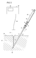
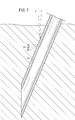
- the indwelling needle 12 In order to puncture the indwelling needle 12, first, as shown in FIG. 5, a medical staff such as a doctor holds the indwelling needle 12 including the puncture needle 10 and punctures it toward the blood vessel (vein) of the patient 50, By gradually inserting the puncture needle 10 toward the desired site, the tip of the puncture needle 10 advances while opening the body tissue 52. At this time, as shown in FIG. 6, the puncture needle 10 is inserted into the catheter 14, and in this state, the concavo-convex portion 22 of the puncture needle 10 is located inside the catheter 14. For this reason, the indentation needle 12 is punctured without the uneven
- FIG. 5 a medical staff such as a doctor holds the indwelling needle 12 including the puncture needle 10 and punctures it toward the blood vessel (vein) of the patient 50, By gradually inserting the puncture needle 10 toward the desired site, the tip of the puncture needle 10 advances while
- the probe 42 of the ultrasonic imaging device 40 is pressed against the vicinity of the puncture site of the patient 50 to irradiate an echo beam (ultrasound) E.
- the probe 42 is configured to transmit an echo beam E and receive a reflected wave (reflected echo) of the echo beam E.
- the echo beam E is transmitted from the skin surface of the patient 50 toward the inside, and is applied to the distal end portion of the indwelling needle 12. Then, as shown in FIG. 6, the echo beam E is reflected to the probe 42 side by the inner wall surface of the inner circumferential groove portion 20 formed on the inner circumferential surface of the catheter 14 and sealed inside the inner circumferential groove portion 20. It is also reflected by the air that is being applied.
- the ultrasonic wave (reflected wave) reflected by the inner circumferential groove 20 is shown as a reflected echo E1.
- the reflected echo E1 reflected by the inner wall surface of the inner circumferential groove portion 20 is not attenuated by the air in the inner circumferential groove portion 20, and has an intensity substantially equal to the intensity of the irradiated echo beam E.
- the reflected echo E1 is received by the probe 42.
- the echo beam E passes through the catheter 14 and is reflected to the probe 42 side at the concavo-convex portion 22.
- the ultrasonic wave reflected by the uneven portion 22 is shown as a reflection echo E2.
- the reflection echo E ⁇ b> 2 reflected by the concavo-convex portion 22 includes a reflection component by the groove portion 24 and a reflection component by the raised portion 26.
- the reflected echo E ⁇ b> 2 reflected by the uneven portion 22 is received by the probe 42.
- the groove portion 24 is formed in an arc shape in cross section
- the inner wall surface forms an arc-shaped reflection surface
- the raised portion 26 is formed in an arc shape in cross section, and the outer wall surface thereof. Constitutes an arcuate reflecting surface. Therefore, even when the puncture angle ⁇ (see FIG. 5) of the indwelling needle 12 is changed, the echo beam E transmitted from the probe 42 by the inner wall surface of the groove portion 24 and the outer wall surface of the raised portion 26 is directed to the probe 42 side. It becomes possible to reflect toward.
- the received data is output from the probe 42 to the control unit (not shown) of the ultrasonic imaging apparatus 40 through the lead wire 44.
- the images of the catheter 14 and the puncture needle 10 displayed on the display 46 are displayed linearly by the length along the axial direction of the concavo-convex portion 22 detected by the ultrasonic imaging device 40. It can be confirmed from the display 46 whether or not the tip has reached the blood vessel (vein) of the patient 50.
- the vicinity of the tip of the puncture needle 10 is clearly displayed as an image on the display 46 of the ultrasonic imaging apparatus 40, and the position of the puncture needle 10 constituting the indwelling needle 12 is confirmed with high accuracy.
- the doctor or the like moves the puncture needle 10 and the probe 42 while confirming the display 46, and guides the puncture needle 10 to the blood vessel of the patient 50.
- the indwelling needle 12 is advanced while appropriately pulling the plunger 34 of the syringe 30.
- the catheter 14 was left, the puncture needle 10 and the syringe 30 were removed, and a guide wire (not shown) was inserted into the blood vessel via the catheter 14. Later, the catheter 14 is removed. Next, a central venous catheter (not shown) is placed in the blood vessel along the guide wire. Next, an infusion line (not shown) is connected to the central artery catheter to supply nutrients, chemicals, and the like into the blood vessel.
- the puncture needle 10 When the puncture needle 10 is removed while leaving the catheter 14, the puncture needle 10 is removed from the patient's body through the inside (lumen) of the catheter 14. The uneven portion 22 does not contact the body tissue 52.
- the uneven portion 22 includes the groove portion 24 and the raised portions 26 provided on both sides thereof, so that the ultrasonic wave is not only the groove portion 24 but also the raised portion. 26 also reflects. Accordingly, it is possible to reliably and suitably reflect the ultrasonic wave and detect it by the ultrasonic imaging apparatus 40. As a result, the puncture needle 10 punctured by the patient can be confirmed reliably and with high accuracy by the ultrasonic imaging device 40, and a safe and reliable procedure can be performed while confirming the position of the puncture needle 10. .
- the concavo-convex portion 22 is formed in an annular shape, the entire circumference serves as a reflection surface, and effectively reflects ultrasonic waves regardless of the position around the axis of the puncture needle 10 at the time of puncture. It becomes possible to make it.
- the concavo-convex portions 22 in the axial direction of the puncture needle 10, more portions that appropriately reflect ultrasonic waves are provided accordingly. Therefore, it is possible to effectively reflect the ultrasonic wave and obtain a more sufficient reflected wave. As a result, the position of the puncture needle 10 can be confirmed with higher accuracy by the ultrasonic imaging apparatus 40.
- the groove portion 24 is formed in an arc shape in cross section, its inner wall surface forms an arc-shaped reflection surface, and the raised portion 26 is formed in an arc shape in cross section, and its outer wall surface is in an arc shape.
- the reflective surface is configured. Therefore, even when the puncture angle ⁇ (see FIG. 5) of the indwelling needle 12 is changed, the ultrasonic waves transmitted from the probe 42 by the inner wall surface of the groove 24 and the outer wall surface of the raised portion 26 are directed toward the probe 42 side. Can be reflected. In other words, regardless of the puncture angle ⁇ of the indwelling needle 12, the ultrasonic wave can be reflected toward the probe 42 and the position of the indwelling needle 12 can be confirmed.
- the inner circumferential groove portion 20 is formed on the inner circumferential surface of the catheter 14 and the ultrasonic waves are reflected also in the inner circumferential groove portion 20, the intensity of the reflected wave received by the probe 42 can be increased, and the clearer An echo image is obtained, and as a result, the position of the distal end portion of the indwelling needle 12 can be confirmed with high accuracy.
- the puncture needle 10 of this invention is a figure.
- the present invention can also be used when a puncture needle 10 is directly punctured into a patient to secure a blood vessel without using the catheter 14.
- a Y hub (not shown) is connected to the proximal end portion of the inner needle hub 18, and a guide wire and a central artery catheter are passed through the Y hub, the inner needle hub 18 and the puncture needle 10 in the same manner as described above. It is possible to perform the procedure.
- the ultrasonic wave (echo beam E) is reliably and suitably reflected by the concave and convex portion 22, and the puncture needle 10 punctured by the patient is confirmed surely and with high accuracy by the ultrasonic imaging device 40.
- a safe and reliable procedure can be performed while confirming the position of the puncture needle 10.
- the puncture needle 10 has been described as a guide wire introduction needle used when a central artery catheter is indwelled by the Seldinger method, the puncture needle 10 of the present invention is erased. It can also be used as an indwelling needle used for infusion by indwelling in a blood vessel, a biopsy needle used for collecting a part of living tissue or cells, and the like.
- FIG. 8 is a side configuration diagram showing the distal end portion of the ultrasonic guide puncture needle 10a (hereinafter simply referred to as “puncture needle 10a”) according to the first modification and the vicinity thereof.
- the plurality of uneven portions 22 may be formed so that the raised portions 26 of the adjacent uneven portions 22 are continuous (connected).
- the concave and convex portion 22 of the puncture needle 10 continuously, it is possible to increase the amount of reflected waves toward the probe 42 compared to the puncture needle 10 according to the basic shape described above. Become.
- the position of the puncture needle 10a can be confirmed with higher accuracy by the ultrasonic imaging apparatus 40.
- FIG. 9 is a side configuration diagram showing the distal end portion of the ultrasonic guide puncture needle 10b (hereinafter simply referred to as “puncture needle 10b”) according to the second modified example and the vicinity thereof.
- the uneven portion 27 having the groove portion 28 and the raised portions 29 provided on both sides of the groove portion 28 circulates at least a plurality of times on the outer peripheral surface of the puncture needle 10b. It may be formed in a spiral shape extending in the axial direction.
- the concavo-convex portion 27 configured in this manner, it is possible to effectively reflect the ultrasonic wave and obtain a more sufficient reflected wave, similarly to the concavo-convex portion 22 described above. As a result, the position of the puncture needle 10b can be confirmed with higher accuracy by the ultrasonic imaging apparatus 40.
- the concavo-convex portion 27 of the puncture needle 10b is formed in a spiral shape, the phase in the axial direction of the plurality of inner peripheral groove portions 20 and the phase in the axial direction of the concavo-convex portions 27 when inserted into the catheter 14 It becomes easy to shift each other.
- the axis of the inner circumferential groove 20 can also be formed by forming the inner circumferential groove 20 of the catheter 14 in a spiral having an angle different from that of the concave / convex 27 or a spiral in a direction different from that of the concave / convex 27. It is easy to shift the phase of the direction and the phase of the concavo-convex portion 27 in the axial direction.
- phase in the axial direction of the inner circumferential groove 20 and the phase in the axial direction of the concavo-convex portion 27 are shifted from each other, it is possible to suppress the attenuation of the reflection intensity of the ultrasonic waves.
Abstract
留置針(12)の内針を構成する超音波ガイド穿刺針(10)は、超音波を反射させる凹凸部(22)を有する。凹凸部(22)は、刃面(11)を有する先端部の近傍の外周面に設けられた溝部(24)と、溝部(24)の両側に設けられた隆起部(26)とを備える。
Description
本発明は、超音波の反射を利用して位置を検出しながら穿刺するための超音波ガイド穿刺針及び留置針に関する。
例えば、患者に高濃度の栄養剤を輸液する際には、カテーテル(外針)及び穿刺針(内針)を含む留置針を患者に穿刺して、穿刺針を抜去し、カテーテルを穿刺した状態のまま残し、カテーテルを介してガイドワイヤーを挿入し、心臓に近い血管(静脈)まで到達させた後、カテーテルを抜去して、中心動脈カテーテルをガイドワイヤーに沿って血管内に挿入し、ガイドワイヤーを取り除いて、中心動脈カテーテルだけを穿刺したまま留置し、中心動脈カテーテルに栄養剤、薬液等の供給される輸液ラインを接続して輸液する。
このような留置針を穿刺する場合には、例えば、超音波撮像装置から超音波を発信し、穿刺する血管の位置を確認すると共に、穿刺した穿刺針に前記超音波を照射し、その反射波に基づいて得られた画像によって前記穿刺針の位置を確認しながら施術が行われている。
従来、このような留置針において、穿刺針(内針)の外周面に凹状の螺旋溝やV溝が形成されたものが知られている(例えば、特許第3171525号公報、特開平3-228748号公報を参照)。この種の留置針の使用に際しては、穿刺針を患者の患部に穿刺し、その穿刺部位に対して超音波撮像装置から超音波を照射することにより、螺旋溝内のエア層又はV溝に前記超音波を反射させ、その反射波を超音波撮像装置で受信することによって穿刺針の撮像画像(エコー画像)を得ている。
ところで、前述した穿刺針の位置を正確に把握するためには、鮮明なエコー画像を取得することが重要であり、鮮明なエコー画像を得るためには穿刺針から超音波撮像装置のプローブへ十分な強度の反射波が帰ってくる必要がある。従って、より強い反射波が得られ、より鮮明なエコー画像を取得することが可能な超音波ガイド穿刺針の開発が望まれる。
本発明は上記の課題に鑑みてなされたものであり、超音波をより効果的に反射させることができ、これにより、体内における位置を確実且つ高精度に確認することができる超音波ガイド穿刺針及び留置針を提供することを目的とする。
本発明は、超音波を反射させる凹凸部を有する超音波ガイド穿刺針であって、前記凹凸部は、刃面を有する先端部の近傍の外周面に設けられた溝部と、前記溝部の両側に設けられた隆起部とを備える、ことを特徴とする。
このように、凹凸部が、溝部とその両側に設けられた隆起部とからなるので、超音波は溝部だけでなく隆起部においても反射する。従って、超音波を確実且つ好適に反射させて超音波撮像装置で検出することができる。その結果、患者に穿刺された超音波ガイド穿刺針を超音波撮像装置によって確実且つ高精度に確認することができ、超音波ガイド穿刺針の位置を確認しながら安全且つ確実な手技を行うことが可能となる。
また、上記の超音波ガイド穿刺針において、前記凹凸部は、前記外周面に環状に形成され、且つ、前記超音波ガイド穿刺針の軸線方向に複数設けられる、ことを特徴とする。
このような構成によれば、凹凸部が、外周面に環状に形成されることで、全周が反射面となり、穿刺時における超音波ガイド穿刺針の軸線回りの位置によらず、超音波を効果的に反射させることが可能となる。また、凹凸部が、超音波ガイド穿刺針の軸線方向に複数設けられることで、その分、超音波を好適に反射する箇所が多く設けられることになる。従って、超音波を効果的に反射させ、より十分な反射波を得ることが可能となる。この結果、超音波撮像装置による超音波ガイド穿刺針の位置の確認をより高精度に行うことが可能となる。
また、上記の超音波ガイド穿刺針において、前記複数の凹凸部は、隣接する前記凹凸部の前記隆起部同士が連続して形成されている、ことを特徴とする。
このように、超音波ガイド穿刺針の軸線方向にわたって凹凸部が連続的に形成されることで、超音波をより効果的に反射させ、より十分な反射波を得ることが可能となる。この結果、超音波撮像装置による超音波ガイド穿刺針の位置の確認をより高精度に行うことが可能となる。
また、上記の超音波ガイド穿刺針において、前記凹凸部は、前記外周面を少なくとも複数回周回する螺旋状に形成される、ことを特徴とする。
上記のように凹凸部が形成されることにより、全周が反射面となり、穿刺時における超音波ガイド穿刺針の軸線回りの位置によらず、超音波を効果的に反射させることが可能となり、また、超音波を好適に反射する箇所が多く設けられることになることから、より十分な反射波を得ることが可能となる。この結果、超音波撮像装置による超音波ガイド穿刺針の位置の確認をより高精度に行うことが可能となる。
また、上記の超音波ガイド穿刺針において、前記溝部は、断面円弧状に形成されている、ことを特徴とする。
上記の構成によれば、溝部の内壁面が円弧状の反射面を構成するため、穿刺角度を変えても、溝部に入射した超音波を入射方向と略同じ方向に反射させることができる。従って、超音波を好適に反射させることが可能となり、結果として、超音波撮像装置による超音波ガイド穿刺針の位置の確認をより高精度に行うことが可能となる。
また、上記の超音波ガイド穿刺針において、前記隆起部は、断面円弧状に形成されている、ことを特徴とする。
上記の構成によれば、隆起部の外壁面が円弧状の反射面を構成するため、穿刺角度を変えても、隆起部に入射した超音波を入射方向と略同じ方向に反射させることができる。従って、超音波を好適に反射させることが可能となり、結果として、超音波撮像装置による超音波ガイド穿刺針の位置の確認をより高精度に行うことが可能となる。
また、本発明は、内針と、前記内針が挿入される外針とを有する留置針であって、前記内針は、超音波を反射させる凹凸部を有する超音波ガイド穿刺針として構成され、前記凹凸部は、刃面を有する先端部の近傍の外周面に設けられた溝部と、前記溝部の両側に設けられた隆起部とを有することを特徴とする。
以下、本発明に係る超音波ガイド穿刺針及び留置針について好適な実施の形態を挙げ、添付の図面を参照しながら説明する。
図1は、本発明の一実施形態に係る超音波ガイド穿刺針10(以下、単に「穿刺針」という。)を備えた留置針12の一構成例を示す全体構成図である。なお、説明の都合上、各添付図面(一部の図面を除く)において、留置針12の軸線方向、及びこの留置針12を構成する各部材の軸線方向を矢印X方向で示す。また、留置針12及びその各部材の先端部側の方向をX1で示し、各部材の基端部側の方向をX2で示す。
図1に示すように、一構成例に係る留置針12は、カテーテル14と、カテーテル14の基端部に結合された外針ハブ16と、カテーテル14の内部に挿通される穿刺針10と、穿刺針10の基端部に結合された内針ハブ18とを有する。
内針ハブ18は、外針ハブ16の内部に嵌合するように構成されている。図1では、穿刺針10及び内針ハブ18の結合体が、カテーテル14及び外針ハブ16の結合体に嵌挿された状態が示されており、この状態において、穿刺針10の先端部に形成された刃面11が、カテーテル14の先端より露出(突出)している。内針ハブ18の基端部には、シリンジ30(図5参照)を接続することができる。
図2Aは、図1に示した留置針12のカテーテル14及び外針ハブ16を示す平面構成図である。一構成例に係る留置針12において、カテーテル14は外針を構成するものであり、例えば、透明な樹脂製材料からなり、適度な弾性を有し、穿刺針10を囲繞するように管状に形成されている。このカテーテル14は、穿刺針10の先端近傍まで達しており、穿刺針10の先端が血管内に挿入されると、カテーテル14も同一の血管内に挿入されることとなる。
カテーテル14の構成材料としては、例えば、エチレン-テトラフルオロエチレン共重合体(ETFE)、ポリウレタン、ポリエーテルナイロン樹脂等の各種軟性樹脂が挙げられる。外針ハブ16の構成材料としては、例えば、ポリエチレン、ポリプロピレン、エチレン-酢酸ビニル共重合体等のポリオレフィン、ポリ塩化ビニル、ポリメチルメタクリレート、ポリカーボネート、ポリブタジエン、ポリアミド、ポリエステル等が挙げられる。
図2Bは、カテーテル14の先端部及びその近傍箇所の軸線方向に沿った一部省略拡大断面図である。図2Bに示すように、カテーテル14の先端部近傍の内周面には、外周側に凸となるように窪んだ内周溝部20が形成されている。図示例の内周溝部20は、断面略半円状であり、周方向に略一定深さで環状に形成されており、軸線方向に所定間隔をおいて所定範囲(図2A中のAで示す範囲)にわたって形成されている。
カテーテル14の最先端部から、最も先端部側の内周溝部20までの距離L1は、例えば、0~3mm、好ましくは1~2mmに設定される。カテーテル14の最先端部から、最も基端部側の内周溝部20までの軸線方向(X方向)の距離L2は、例えば、2~10mm、好ましくは6~8mmに設定される。内周溝部20の半径方向の深さは、例えば、10~25μmに設定される。複数の内周溝部20の溝ピッチ(軸線方向の間隔)は、例えば、0.2~0.5mmに設定される。
なお、内周溝部20は、環状の溝を軸線方向に間隔を置いて形成したものに限られず、軸線方向に螺旋状に延在する溝に形成したものであってもよい。また、内周溝部20は、省略されてもよい。
図3Aは、本発明の一実施形態に係る穿刺針10と内針ハブ18を示す平面構成図である。一構成例に係る留置針12において、穿刺針10は内針を構成するものである。穿刺針10は、中空の管体であって、その先端部には、軸線に対して傾斜した刃面11が形成されている。
穿刺針10の構成材料としては、十分な穿刺力(貫通力)が得られる程度に刃先を鋭利に形成でき、且つ、穿刺に必要な強度を持つ材料が使用され、例えば、ステンレス鋼、アルミニウム合金、銅合金等が挙げられる。
穿刺針10の基端部は、内針ハブ18の先端部に結合され保持されている。内針ハブ18の構成材料としては、上述した外針ハブ16と同様の構成材料が挙げられる。図3Aに示すように、穿刺針10の先端部の近傍(刃面11より基端部側の所定範囲)の外周面には、超音波を反射させる凹凸部22が、軸線方向の所定範囲にわたって設けられている。
図3Bは、図3Aに示した穿刺針10の凹凸部22を示す一部断面拡大側面図である。穿刺針10の外径Dは、例えば、0.7~0.8mmに設定される。本実施の形態において、凹凸部22は、穿刺針10の外周面に環状に形成され、且つ、穿刺針10の軸線方向(X方向)に間隔を置いて複数設けられる。図示例のように、各凹凸部22の軸線方向の間隔L3は同一に設定してもよく、この場合、間隔L3は、例えば、200~500μmに設定される。
穿刺針10の最先端部から最も先端部側の凹凸部22までの軸線方向の距離L4(図3A参照)は、例えば、0.3~5mmに設定される。穿刺針10の最先端部から最も基端部側の凹凸部22までの軸線方向の距離L5(図3A参照)は、例えば、5~50mmに設定される。
なお、図示例の穿刺針10では、各凹凸部22の軸線方向の間隔L3は、同一に設定されているが、複数の凹凸部22の各間隔の一部又は全部を異ならせて設定してもよい。例えば、穿刺針10の先端部側ほど凹凸部22の間隔を小さくする(穿刺針10の基端部側ほど凹凸部22の間隔を大きくする)ようにしてもよい。
図3Bに示すように、凹凸部22は、内周側に凸形状となる環状の溝部24と、溝部24の両側(軸線方向の両側)に設けられ、半径方向外側に凸形状となる環状の隆起部26とを有する。
本実施の形態において、溝部24は、断面円弧状であり、周方向にわたって略一定深さで形成されている。溝部24の軸線方向の幅W1は、例えば、30~100μmに設定される。溝部24の半径方向の深さH1は、例えば、5~20μmに設定される。
本実施の形態において、隆起部26は、断面円弧状であり、周方向にわたって略一定高さで形成されている。隆起部26の軸線方向の幅W2は、例えば、5~20μmに設定される。隆起部26の半径方向の高さH2は、例えば、1~15μmに設定される。
なお、上記のように構成される凹凸部22は、管状素材(ワーク)に対して、塑性加工、切削加工、放電加工等の機械加工を施すことで、比較的簡単に形成することができる。
図4は、本発明の一実施形態に係る穿刺針10をカテーテル14に嵌挿し、穿刺針10の刃面11を含む先端部がカテーテル14の先端部から露出(突出)した状態を示す一部省略拡大断面図である。カテーテル14の内径は、隆起部26が設けられた穿刺針10を挿入できるように、隆起部26の外径と略同じか、それより僅かに大きく設定されている。
また、図4に示すように、本実施の形態では、カテーテル14及び穿刺針10において、内周溝部20と凹凸部22は、穿刺針10の先端部がカテーテル14の先端部から所定長さ露出(突出)した状態で、複数の内周溝部20の軸線方向の位相と、複数の凹凸部22が軸線方向の位相とが、互いにずれるように形成されている。
本実施の形態に係る穿刺針10を含む留置針12は、基本的には以上のように構成されるものであり、次にその使用方法並びに作用効果について説明する。
留置針12の穿刺に先立ち、図5に示すように、内針ハブ18の基端部にはシリンジ30が接続される。シリンジ30は、円筒状のシリンジ本体32と、シリンジ本体32の内部に挿入されるプランジャ34とを含む。シリンジ本体32の先端部には接続ポート36が設けられ、この接続ポート36が内針ハブ18の基端部に接続されている。これにより、シリンジ30は、接続ポート36を介して、内針ハブ18の内部と連通している。
留置針12を穿刺するには、先ず、図5に示すように、医師等の医療従事者が穿刺針10を含む留置針12を把持して患者50の血管(静脈)に向かって穿刺し、穿刺針10を所望部位に向けて徐々に挿入していくことにより、その先端部が体内組織52を切り開きながら進む。この際、図6に示されるように、穿刺針10は、カテーテル14の内部に挿通されており、この状態では、穿刺針10の凹凸部22はカテーテル14の内部に位置している。このため、穿刺針10の凹凸部22は、体内組織52に接することなく、留置針12が穿刺される。
一方、留置針12を患者に穿刺すると同時に、超音波撮像装置40のプローブ42を患者50の穿刺部位近傍に対して押し当てエコービーム(超音波)Eを照射する。なお、このプローブ42は、エコービームEを発信し、エコービームEの反射波(反射エコー)を受信可能に構成されている。
エコービームEは、患者50の皮膚表面から内部に向かって発信され、留置針12の先端部に照射される。そして、エコービームEは、図6に示されるように、カテーテル14の内周面に形成された内周溝部20の内壁面によってプローブ42側に反射されるとともに、内周溝部20の内部に密封されている空気によっても同様に反射される。ここで、内周溝部20によって反射された超音波(反射波)を、反射エコーE1として示す。この場合、内周溝部20の内壁面で反射された反射エコーE1は、内周溝部20内の空気によって減衰されることがなく、照射されたエコービームEの強さと略同等の強度をもつ。反射エコーE1は、プローブ42によって受信される。
また、エコービームEは、カテーテル14を透過し、凹凸部22においてプローブ42側に反射される。ここで、凹凸部22によって反射された超音波を、反射エコーE2として示す。凹凸部22によって反射された反射エコーE2には、溝部24による反射成分と、隆起部26による反射成分とがある。凹凸部22によって反射された反射エコーE2は、プローブ42によって受信される。
上述したように、本実施の形態において、溝部24は、断面円弧状に形成され、その内壁面が円弧状の反射面を構成し、隆起部26は、断面円弧状に形成され、その外壁面が円弧状の反射面を構成する。このため、留置針12の穿刺角度θ(図5参照)を変化させた場合でも、溝部24の内壁面及び隆起部26の外壁面によってプローブ42から発信されたエコービームEを、プローブ42側に向かって反射させることが可能となる。
エコービームEの反射波(反射エコーE1、E2)がプローブ42によって受信されると、この受信したデータがプローブ42からリード線44を通じて超音波撮像装置40の制御部(図示せず)へと出力されて処理され、その後に、ディスプレイ46に画像として表示される。具体的には、ディスプレイ46に表示されるカテーテル14及び穿刺針10の画像は、超音波撮像装置40によって検出される凹凸部22の軸線方向に沿った長さ分だけ線状に表示され、その先端部が患者50の血管(静脈)に到達しているか否かをディスプレイ46から確認することができる。
その結果、穿刺針10の先端部近傍が、超音波撮像装置40のディスプレイ46に画像として鮮明に表示され、留置針12を構成する穿刺針10の位置が高精度に確認される。
そして、医師等は、ディスプレイ46を確認しながら穿刺針10及びプローブ42を移動させ、穿刺針10を患者50の血管へと導く。このとき、シリンジ30のプランジャ34を適度に引きながら留置針12を進めていく。この穿刺針10が血管に正しく穿刺されると、血液がシリンジ30の接続ポート36を通じてシリンジ本体32へと導入されてフラッシュバックが発生する。
このように、穿刺針10が血管に穿刺されたことが確認された後、カテーテル14を残して、穿刺針10及びシリンジ30を取り除き、カテーテル14を介して血管内に図示しないガイドワイヤーを挿入した後に、カテーテル14を除去する。次いで、前記ガイドワイヤーに沿って、図示しない中心静脈カテーテルを血管内に留置する。次いで、図示しない輸液ラインを中心動脈カテーテルに接続して血管内に栄養剤、薬液等を供給する。
カテーテル14を残して穿刺針10を抜去する際には、穿刺針10は、カテーテル14の内部(内腔)を通って患者の体外に抜去されるため、穿刺時と同様に、穿刺針10の凹凸部22が体内組織52に接することがない。
以上のように、本実施の形態に係る穿刺針10によれば、凹凸部22が、溝部24とその両側に設けられた隆起部26とからなるので、超音波は溝部24だけでなく隆起部26においても反射する。従って、超音波を確実且つ好適に反射させて超音波撮像装置40で検出することができる。その結果、患者に穿刺された穿刺針10を超音波撮像装置40によって確実且つ高精度に確認することができ、穿刺針10の位置を確認しながら安全且つ確実な手技を行うことが可能となる。
また、本実施の形態では、凹凸部22が、環状に形成されているので、全周が反射面となり、穿刺時における穿刺針10の軸線回りの位置によらず、超音波を効果的に反射させることが可能となる。また、凹凸部22が、穿刺針10の軸線方向に複数設けられることで、その分、超音波を好適に反射する箇所が多く設けられることになる。従って、超音波を効果的に反射させ、より十分な反射波を得ることが可能となる。この結果、超音波撮像装置40による穿刺針10の位置の確認をより高精度に行うことが可能となる。
さらに、本実施の形態では、溝部24は、断面円弧状に形成され、その内壁面が円弧状の反射面を構成し、隆起部26は、断面円弧状に形成され、その外壁面が円弧状の反射面を構成する。このため、留置針12の穿刺角度θ(図5参照)を変化させた場合でも、溝部24の内壁面及び隆起部26の外壁面によってプローブ42から発信された超音波を、プローブ42側に向かって反射させることが可能となる。換言すれば、留置針12の穿刺角度θに関わらず、超音波をプローブ42側に向かって反射させ、留置針12の位置を確認することができる。
さらにまた、カテーテル14の内周面には内周溝部20が形成され、内周溝部20においても超音波を反射させるので、プローブ42で受信する反射波の強度を高めることができ、より鮮明なエコー画像が得られ、この結果、留置針12の先端部の位置を高精度に確認することが可能となる。
なお、上記本実施の形態に係る穿刺針10について、外針と内針とを有する留置針12の内針として構成された場合の使用形態を説明したが、本発明の穿刺針10は、図7に示すように、カテーテル14を用いずに、穿刺針10を直接、患者に穿刺して血管確保を行う場合にも使用可能である。この場合、内針ハブ18の基端部に、例えば、Yハブ(図示せず)を接続し、このYハブ、内針ハブ18及び穿刺針10にガイドワイヤー及び中心動脈カテーテルを通して、上記と同様の手技を行うことが可能である。このような使用形態においても、超音波(エコービームE)を凹凸部22によって確実且つ好適に反射させ、患者に穿刺された穿刺針10を超音波撮像装置40によって確実且つ高精度に確認することができ、穿刺針10の位置を確認しながら安全且つ確実な手技を行うことが可能となる。
また、本実施の形態に係る穿刺針10について、セルジンガー法によって中心動脈カテーテルを留置する際に使用するガイドワイヤー導入針として用いる場合の形態を説明したが、本発明の穿刺針10は、抹消血管に留置して輸液する際に使用する留置針、生体組織や細胞の一部を採取する際に使用する生検針などとしても用いることができる。
図8は、第1変形例に係る超音波ガイド穿刺針10a(以下、単に「穿刺針10a」という。)の先端部及びその近傍箇所を示す側面構成図である。第1変形例に係る穿刺針10aのように、隣接する凹凸部22の隆起部26同士が連続(連結)するように複数の凹凸部22が形成されてもよい。このように、穿刺針10の凹凸部22が連続的に形成されることで、上述した基本形に係る穿刺針10と比較して、プローブ42側に向かう反射波の量を多くすることが可能となる。この結果、超音波撮像装置40による穿刺針10aの位置の確認を一層高精度に行うことが可能となる。
図9は、第2変形例に係る超音波ガイド穿刺針10b(以下、単に「穿刺針10b」という。)の先端部及びその近傍箇所を示す側面構成図である。第2変形例に係る穿刺針10bのように、溝部28と、この溝部28の両側に設けられた隆起部29とを有する凹凸部27が、穿刺針10bの外周面を少なくとも複数回周回して軸線方向に延在する螺旋状に形成されてもよい。このように構成された凹凸部27によっても、前述した凹凸部22と同様に、超音波を効果的に反射させ、より十分な反射波を得ることが可能となる。この結果、超音波撮像装置40による穿刺針10bの位置の確認をより高精度に行うことが可能となる。
また、穿刺針10bの凹凸部27が螺旋状に形成されていることにより、カテーテル14に挿入したときに、複数の内周溝部20の軸線方向の位相と、凹凸部27の軸線方向の位相とを互いにずらすことが容易となる。
また、カテーテル14の内周溝部20を凹凸部27とは異なる角度の螺旋状に形成したり、凹凸部27とは異なる方向の螺旋状に形成したりすることによっても、内周溝部20の軸線方向の位相と、凹凸部27の軸線方向の位相とを互いにずらすことが容易となる。
内周溝部20の軸線方向の位相と、凹凸部27の軸線方向の位相とが互いにずれていると、超音波の反射強度が減衰することを抑制することができる。
なお、本発明は、上述の実施の形態に限らず、本発明の要旨を逸脱することなく、種々の構成を採り得ることは勿論である。
Claims (7)
- 超音波を反射させる凹凸部(22、27)を有する超音波ガイド穿刺針(10、10a、10b)であって、
前記凹凸部(22、27)は、
刃面(11)を有する先端部の近傍の外周面に設けられた溝部(24、28)と、
前記溝部(24、28)の両側に設けられた隆起部(26、29)とを備える、
ことを特徴とする超音波ガイド穿刺針(10、10a、10b)。 - 請求項1記載の超音波ガイド穿刺針(10、10a)において、
前記凹凸部(22)は、前記外周面に環状に形成され、且つ、前記超音波ガイド穿刺針(10、10a)の軸線方向に複数設けられる、
ことを特徴とする超音波ガイド穿刺針(10、10a)。 - 請求項2記載の超音波ガイド穿刺針(10、10a)において、
前記複数の凹凸部(22)は、隣接する前記凹凸部(22)の前記隆起部(26)同士が連続して形成されている、
ことを特徴とする超音波ガイド穿刺針(10、10a)。 - 請求項1記載の超音波ガイド穿刺針(10b)において、
前記凹凸部(27)は、前記外周面を少なくとも複数回周回する螺旋状に形成される、
ことを特徴とする超音波ガイド穿刺針(10b)。 - 請求項1記載の超音波ガイド穿刺針(10、10a、10b)において、
前記溝部(24、28)は、断面円弧状に形成されている、
ことを特徴とする超音波ガイド穿刺針(10、10a、10b)。 - 請求項1記載の超音波ガイド穿刺針(10、10a、10b)において、
前記隆起部(26、29)は、断面円弧状に形成されている、
ことを特徴とする超音波ガイド穿刺針(10、10a、10b)。 - 内針と、前記内針が挿入される外針とを有する留置針(12)であって、
前記内針は、超音波を反射させる凹凸部(22、27)を有する超音波ガイド穿刺針(10、10a、10b)として構成され、
前記凹凸部(22、27)は、
刃面(11)を有する先端部の近傍の外周面に設けられた溝部(24、28)と、
前記溝部(24、28)の両側に設けられた隆起部(26、29)とを有する、
ことを特徴とする留置針(12)。
Priority Applications (4)
| Application Number | Priority Date | Filing Date | Title |
|---|---|---|---|
| US13/515,403 US9592352B2 (en) | 2009-12-21 | 2010-11-01 | Ultrasound-guided piercing needle and indwelling needle |
| JP2011547387A JP5802135B2 (ja) | 2009-12-21 | 2010-11-01 | 超音波ガイド穿刺針及び留置針 |
| CN201080046771.4A CN103732273B (zh) | 2009-12-21 | 2010-11-01 | 超声波导向穿刺针及留置针 |
| EP10839073.3A EP2517745B1 (en) | 2009-12-21 | 2010-11-01 | Ultrasound-guided piercing needle and indwelling needle |
Applications Claiming Priority (2)
| Application Number | Priority Date | Filing Date | Title |
|---|---|---|---|
| JP2009289598 | 2009-12-21 | ||
| JP2009-289598 | 2009-12-21 |
Publications (1)
| Publication Number | Publication Date |
|---|---|
| WO2011077837A1 true WO2011077837A1 (ja) | 2011-06-30 |
Family
ID=44195382
Family Applications (1)
| Application Number | Title | Priority Date | Filing Date |
|---|---|---|---|
| PCT/JP2010/069401 WO2011077837A1 (ja) | 2009-12-21 | 2010-11-01 | 超音波ガイド穿刺針及び留置針 |
Country Status (5)
| Country | Link |
|---|---|
| US (1) | US9592352B2 (ja) |
| EP (1) | EP2517745B1 (ja) |
| JP (1) | JP5802135B2 (ja) |
| CN (1) | CN103732273B (ja) |
| WO (1) | WO2011077837A1 (ja) |
Cited By (2)
| Publication number | Priority date | Publication date | Assignee | Title |
|---|---|---|---|---|
| JP2016508797A (ja) * | 2013-02-26 | 2016-03-24 | アレン メーズ, | カラー超音波針 |
| JP2019531793A (ja) * | 2016-08-31 | 2019-11-07 | ソンウォン メディカル シーオー., エルティーディーSungwon Medical Co., Ltd | 超音波生検ガイド画像の視認性のための施術用強化細針 |
Families Citing this family (16)
| Publication number | Priority date | Publication date | Assignee | Title |
|---|---|---|---|---|
| WO2014158951A1 (en) | 2013-03-14 | 2014-10-02 | Muffin Incorporated | Echogenic surfaces with pressed-dimple formations |
| EP3045194B1 (en) * | 2013-09-11 | 2020-06-10 | Terumo Kabushiki Kaisha | Medical hollow needle assembly and method for manufacturing hollow needle |
| US9993263B2 (en) | 2013-12-12 | 2018-06-12 | Catalin Esanu | Method and device for ultrasound guided minimal invasive access of a bodily cavity |
| US9980699B2 (en) * | 2014-09-12 | 2018-05-29 | Cook Medical Technologies Llc | Shaped echogenic needle groove |
| CN104688303B (zh) * | 2015-02-15 | 2017-04-12 | 扬州市江洲医疗器械有限公司 | 无损伤硬膜外导管穿刺针 |
| CN104971406A (zh) * | 2015-05-22 | 2015-10-14 | 南京农业大学 | 一种表面具有微反射器结构的医学用针及其制备方法 |
| EP3367936B1 (en) * | 2015-10-26 | 2023-09-06 | Smiths Medical International Limited | Echogenic needle assemblies |
| EP4074265A1 (en) * | 2015-10-26 | 2022-10-19 | Smiths Medical ASD, Inc. | Echogenic needle |
| USD842984S1 (en) | 2015-12-09 | 2019-03-12 | Dentsply Ih Ab | Catheter |
| CN114848286A (zh) | 2016-12-19 | 2022-08-05 | 新世界医学有限公司 | 眼部治疗装置和相关使用方法 |
| RU2658475C1 (ru) * | 2017-06-09 | 2018-06-21 | Антон Александрович Касаткин | Пункционная игла |
| CN107569258A (zh) * | 2017-09-29 | 2018-01-12 | 上海长海医院 | 一种穿刺针 |
| CN110025872A (zh) * | 2018-01-12 | 2019-07-19 | 美敦力公司 | 一种增强超声下显影性的球囊扩张导管 |
| EP3912559A4 (en) * | 2019-01-17 | 2022-03-23 | FUJIFILM Corporation | PUNCTURE NEEDLE, ULTRASOUND EXAMINATION DEVICE AND METHOD FOR CONTROLLING AN ULTRASOUND EXAMINATION APPARATUS |
| WO2020186419A1 (zh) * | 2019-03-18 | 2020-09-24 | 王沁 | 具有手位的穿刺针 |
| CN112137691B (zh) * | 2019-06-27 | 2023-07-21 | 上海安久生物科技有限公司 | 一种制备超声引导穿刺针的系统 |
Citations (5)
| Publication number | Priority date | Publication date | Assignee | Title |
|---|---|---|---|---|
| JPH03228748A (ja) | 1990-02-02 | 1991-10-09 | Ogura Hisako | 超音波反射体 |
| JPH10248793A (ja) * | 1997-03-14 | 1998-09-22 | Olympus Optical Co Ltd | 処置具 |
| JP3171525B2 (ja) | 1994-04-14 | 2001-05-28 | 康雄 真島 | 医療用穿刺針 |
| WO2007013130A1 (ja) * | 2005-07-25 | 2007-02-01 | Hakko Co., Ltd. | 超音波用穿刺針 |
| JP3890013B2 (ja) * | 2002-12-05 | 2007-03-07 | オリンパス株式会社 | 超音波用穿刺針 |
Family Cites Families (9)
| Publication number | Priority date | Publication date | Assignee | Title |
|---|---|---|---|---|
| DE2425724C3 (de) | 1974-05-28 | 1979-09-27 | Siemens Ag, 1000 Berlin Und 8000 Muenchen | Punktionskanüle |
| US4401124A (en) * | 1981-08-13 | 1983-08-30 | Technicare Corporation | Reflection enhancement of a biopsy needle |
| US4582061A (en) * | 1981-11-18 | 1986-04-15 | Indianapolis Center For Advanced Research, Inc. | Needle with ultrasonically reflective displacement scale |
| US5490521A (en) * | 1993-08-31 | 1996-02-13 | Medtronic, Inc. | Ultrasound biopsy needle |
| US20060047254A1 (en) * | 2003-04-04 | 2006-03-02 | Ravi Nallakrishnan | Phacoemulsification needle |
| DE202005008489U1 (de) * | 2005-05-31 | 2005-09-08 | Medi-Globe Gmbh | Medizinische Vorrichtung, die mittels Ultraschall sichtbar zu machen ist |
| US7682337B2 (en) * | 2007-02-07 | 2010-03-23 | Cook Incorporated | Method and apparatus for gaining percutaneous access to a body |
| JP5108580B2 (ja) * | 2008-03-26 | 2012-12-26 | テルモ株式会社 | 留置針 |
| US9521993B2 (en) * | 2008-12-30 | 2016-12-20 | Boston Scientific Scimed, Inc. | Echogenic enhancement for a needle |
-
2010
- 2010-11-01 EP EP10839073.3A patent/EP2517745B1/en active Active
- 2010-11-01 CN CN201080046771.4A patent/CN103732273B/zh active Active
- 2010-11-01 WO PCT/JP2010/069401 patent/WO2011077837A1/ja active Application Filing
- 2010-11-01 JP JP2011547387A patent/JP5802135B2/ja active Active
- 2010-11-01 US US13/515,403 patent/US9592352B2/en active Active
Patent Citations (5)
| Publication number | Priority date | Publication date | Assignee | Title |
|---|---|---|---|---|
| JPH03228748A (ja) | 1990-02-02 | 1991-10-09 | Ogura Hisako | 超音波反射体 |
| JP3171525B2 (ja) | 1994-04-14 | 2001-05-28 | 康雄 真島 | 医療用穿刺針 |
| JPH10248793A (ja) * | 1997-03-14 | 1998-09-22 | Olympus Optical Co Ltd | 処置具 |
| JP3890013B2 (ja) * | 2002-12-05 | 2007-03-07 | オリンパス株式会社 | 超音波用穿刺針 |
| WO2007013130A1 (ja) * | 2005-07-25 | 2007-02-01 | Hakko Co., Ltd. | 超音波用穿刺針 |
Non-Patent Citations (1)
| Title |
|---|
| See also references of EP2517745A4 * |
Cited By (2)
| Publication number | Priority date | Publication date | Assignee | Title |
|---|---|---|---|---|
| JP2016508797A (ja) * | 2013-02-26 | 2016-03-24 | アレン メーズ, | カラー超音波針 |
| JP2019531793A (ja) * | 2016-08-31 | 2019-11-07 | ソンウォン メディカル シーオー., エルティーディーSungwon Medical Co., Ltd | 超音波生検ガイド画像の視認性のための施術用強化細針 |
Also Published As
| Publication number | Publication date |
|---|---|
| CN103732273A (zh) | 2014-04-16 |
| CN103732273B (zh) | 2017-03-29 |
| US9592352B2 (en) | 2017-03-14 |
| JPWO2011077837A1 (ja) | 2013-05-02 |
| US20120253297A1 (en) | 2012-10-04 |
| EP2517745A4 (en) | 2013-06-05 |
| JP5802135B2 (ja) | 2015-10-28 |
| EP2517745A1 (en) | 2012-10-31 |
| EP2517745B1 (en) | 2019-01-02 |
Similar Documents
| Publication | Publication Date | Title |
|---|---|---|
| JP5802135B2 (ja) | 超音波ガイド穿刺針及び留置針 | |
| JP2011125632A (ja) | 超音波ガイド穿刺針及び留置針 | |
| US8523841B2 (en) | Catheter with spiral slit terminating in slit termination portion oriented to suppress crack occurrence | |
| JP2011125389A (ja) | 留置針 | |
| JP6322210B2 (ja) | 標的化された挿管のためのデバイス、システム、および方法 | |
| JP3171525B2 (ja) | 医療用穿刺針 | |
| AU2009276280A1 (en) | An echogenic medical needle | |
| JP5552050B2 (ja) | 留置針 | |
| JP2011120760A (ja) | 留置針 | |
| JP5191823B2 (ja) | 留置針及び穿刺針 | |
| JP5171355B2 (ja) | 生体内挿入用プローブ装置 | |
| JP6591987B2 (ja) | 医療用デバイス | |
| JP6475367B2 (ja) | 挿入物及びアタッチメント部材 | |
| JP6884538B2 (ja) | 接続ポートおよび医療用デバイス | |
| JP2020127607A (ja) | 埋込体留置具及び埋込体 | |
| JP5634667B2 (ja) | 留置針及びその製造方法 | |
| JP7231639B2 (ja) | 穿刺針 | |
| CN112823756A (zh) | 超声引导神经阻滞穿刺针 | |
| US11517667B2 (en) | Puncture needle | |
| CN219271069U (zh) | 一种钳道式可调弯的超声引导静脉穿刺系统 | |
| JP5889748B2 (ja) | 医療用デバイス | |
| JP2022149295A (ja) | 送達デバイス |
Legal Events
| Date | Code | Title | Description |
|---|---|---|---|
| 121 | Ep: the epo has been informed by wipo that ep was designated in this application |
Ref document number: 10839073 Country of ref document: EP Kind code of ref document: A1 |
|
| WWE | Wipo information: entry into national phase |
Ref document number: 2011547387 Country of ref document: JP |
|
| WWE | Wipo information: entry into national phase |
Ref document number: 13515403 Country of ref document: US |
|
| WWE | Wipo information: entry into national phase |
Ref document number: 2010839073 Country of ref document: EP |
|
| NENP | Non-entry into the national phase |
Ref country code: DE |