WO2011077837A1 - Aiguille de ponction et aiguille à demeure à guidage ultrasonore - Google Patents
Aiguille de ponction et aiguille à demeure à guidage ultrasonore Download PDFInfo
- Publication number
- WO2011077837A1 WO2011077837A1 PCT/JP2010/069401 JP2010069401W WO2011077837A1 WO 2011077837 A1 WO2011077837 A1 WO 2011077837A1 JP 2010069401 W JP2010069401 W JP 2010069401W WO 2011077837 A1 WO2011077837 A1 WO 2011077837A1
- Authority
- WO
- WIPO (PCT)
- Prior art keywords
- puncture needle
- needle
- ultrasonic
- concavo
- ultrasonic guide
- Prior art date
Links
Images


Classifications
-
- A—HUMAN NECESSITIES
- A61—MEDICAL OR VETERINARY SCIENCE; HYGIENE
- A61M—DEVICES FOR INTRODUCING MEDIA INTO, OR ONTO, THE BODY; DEVICES FOR TRANSDUCING BODY MEDIA OR FOR TAKING MEDIA FROM THE BODY; DEVICES FOR PRODUCING OR ENDING SLEEP OR STUPOR
- A61M5/00—Devices for bringing media into the body in a subcutaneous, intra-vascular or intramuscular way; Accessories therefor, e.g. filling or cleaning devices, arm-rests
- A61M5/178—Syringes
- A61M5/31—Details
- A61M5/32—Needles; Details of needles pertaining to their connection with syringe or hub; Accessories for bringing the needle into, or holding the needle on, the body; Devices for protection of needles
- A61M5/329—Needles; Details of needles pertaining to their connection with syringe or hub; Accessories for bringing the needle into, or holding the needle on, the body; Devices for protection of needles characterised by features of the needle shaft
-
- A—HUMAN NECESSITIES
- A61—MEDICAL OR VETERINARY SCIENCE; HYGIENE
- A61M—DEVICES FOR INTRODUCING MEDIA INTO, OR ONTO, THE BODY; DEVICES FOR TRANSDUCING BODY MEDIA OR FOR TAKING MEDIA FROM THE BODY; DEVICES FOR PRODUCING OR ENDING SLEEP OR STUPOR
- A61M5/00—Devices for bringing media into the body in a subcutaneous, intra-vascular or intramuscular way; Accessories therefor, e.g. filling or cleaning devices, arm-rests
- A61M5/14—Infusion devices, e.g. infusing by gravity; Blood infusion; Accessories therefor
- A61M5/158—Needles for infusions; Accessories therefor, e.g. for inserting infusion needles, or for holding them on the body
-
- A—HUMAN NECESSITIES
- A61—MEDICAL OR VETERINARY SCIENCE; HYGIENE
- A61B—DIAGNOSIS; SURGERY; IDENTIFICATION
- A61B17/00—Surgical instruments, devices or methods, e.g. tourniquets
- A61B17/34—Trocars; Puncturing needles
- A61B17/3403—Needle locating or guiding means
- A61B2017/3413—Needle locating or guiding means guided by ultrasound
-
- A—HUMAN NECESSITIES
- A61—MEDICAL OR VETERINARY SCIENCE; HYGIENE
- A61B—DIAGNOSIS; SURGERY; IDENTIFICATION
- A61B90/00—Instruments, implements or accessories specially adapted for surgery or diagnosis and not covered by any of the groups A61B1/00 - A61B50/00, e.g. for luxation treatment or for protecting wound edges
- A61B90/39—Markers, e.g. radio-opaque or breast lesions markers
- A61B2090/3925—Markers, e.g. radio-opaque or breast lesions markers ultrasonic
-
- A—HUMAN NECESSITIES
- A61—MEDICAL OR VETERINARY SCIENCE; HYGIENE
- A61B—DIAGNOSIS; SURGERY; IDENTIFICATION
- A61B8/00—Diagnosis using ultrasonic, sonic or infrasonic waves
- A61B8/08—Detecting organic movements or changes, e.g. tumours, cysts, swellings
- A61B8/0833—Detecting organic movements or changes, e.g. tumours, cysts, swellings involving detecting or locating foreign bodies or organic structures
- A61B8/0841—Detecting organic movements or changes, e.g. tumours, cysts, swellings involving detecting or locating foreign bodies or organic structures for locating instruments
Definitions
- the present invention relates to an ultrasonic guide puncture needle and an indwelling needle for puncturing while detecting a position using reflection of ultrasonic waves.
- the patient is punctured with an indwelling needle including an catheter (outer needle) and a puncture needle (inner needle), the puncture needle is removed, and the catheter is punctured
- the guide wire is inserted through the catheter to reach the blood vessel (vein) close to the heart, then the catheter is removed, and the central artery catheter is inserted into the blood vessel along the guide wire.
- indwelling with only the central arterial catheter punctured, and connecting the central artery catheter with an infusion line to which nutrients, chemicals, etc. are supplied, and transfuses.
- an ultrasonic wave is transmitted from an ultrasonic imaging device, the position of the blood vessel to be punctured is confirmed, the ultrasonic wave is irradiated to the punctured puncture needle, and the reflected wave thereof The treatment is performed while confirming the position of the puncture needle by the image obtained based on the above.
- indwelling needles are known in which a concave spiral groove or V-groove is formed on the outer peripheral surface of a puncture needle (inner needle) (for example, Japanese Patent No. 3171525, Japanese Patent Laid-Open No. 3-228748). Issue no.).
- a puncture needle inner needle
- the puncture needle is punctured into the affected area of the patient, and the puncture site is irradiated with ultrasonic waves from an ultrasonic imaging device, whereby the air layer or V-groove in the spiral groove is By picking up an ultrasonic wave and receiving the reflected wave with an ultrasonic imaging apparatus, an image (echo image) of the puncture needle is obtained.
- the present invention has been made in view of the above-mentioned problems, and an ultrasonic guide puncture needle capable of reflecting ultrasonic waves more effectively and thereby confirming the position in the body reliably and with high accuracy. And to provide an indwelling needle.
- the present invention is an ultrasonic guide puncture needle having a concavo-convex portion for reflecting ultrasonic waves, the concavo-convex portion being provided on a groove portion provided on an outer peripheral surface in the vicinity of a tip portion having a blade surface, and on both sides of the groove portion. And a raised portion provided.
- the concavo-convex portion is composed of the groove portion and the raised portions provided on both sides thereof, the ultrasonic wave is reflected not only at the groove portion but also at the raised portion. Therefore, the ultrasonic wave can be reliably and suitably reflected and detected by the ultrasonic imaging apparatus. As a result, the ultrasonic guide puncture needle punctured by the patient can be reliably and accurately confirmed by the ultrasonic imaging apparatus, and a safe and reliable procedure can be performed while confirming the position of the ultrasonic guide puncture needle. It becomes possible.
- the ultrasonic guide puncture needle is characterized in that the concavo-convex portion is formed in an annular shape on the outer peripheral surface and provided in a plurality in the axial direction of the ultrasonic guide puncture needle.
- the concavo-convex portion is formed in an annular shape on the outer peripheral surface, so that the entire periphery becomes a reflecting surface, and ultrasonic waves are transmitted regardless of the position around the axis of the ultrasonic guide puncture needle at the time of puncturing. It is possible to reflect effectively.
- a lot of portions that suitably reflect ultrasonic waves are provided accordingly. Therefore, it is possible to effectively reflect the ultrasonic wave and obtain a more sufficient reflected wave. As a result, the position of the ultrasonic guide puncture needle can be confirmed with higher accuracy by the ultrasonic imaging apparatus.
- the plurality of concavo-convex portions are characterized in that the raised portions of the adjacent concavo-convex portions are continuously formed.
- the concavo-convex portions are continuously formed over the axial direction of the ultrasonic guide puncture needle, it is possible to more effectively reflect the ultrasonic wave and obtain a more sufficient reflected wave. As a result, the position of the ultrasonic guide puncture needle can be confirmed with higher accuracy by the ultrasonic imaging apparatus.
- the concavo-convex portion is formed in a spiral shape that circulates around the outer peripheral surface at least a plurality of times.
- the entire circumference becomes a reflective surface, and it is possible to effectively reflect ultrasonic waves regardless of the position around the axis of the ultrasonic guide puncture needle at the time of puncturing, In addition, since a lot of locations that appropriately reflect the ultrasonic waves are provided, a more sufficient reflected wave can be obtained. As a result, the position of the ultrasonic guide puncture needle can be confirmed with higher accuracy by the ultrasonic imaging apparatus.
- the groove is formed in an arc shape in cross section.
- the inner wall surface of the groove portion forms an arc-shaped reflection surface, even if the puncture angle is changed, the ultrasonic wave incident on the groove portion can be reflected in the substantially same direction as the incident direction. Accordingly, it is possible to suitably reflect the ultrasonic wave, and as a result, the position of the ultrasonic guide puncture needle can be confirmed with higher accuracy by the ultrasonic imaging apparatus.
- the raised portion is formed in an arc shape in cross section.
- the outer wall surface of a protruding part comprises an arc-shaped reflective surface, even if it changes a puncture angle, the ultrasonic wave which injected into the protruding part can be reflected in the substantially the same direction as an incident direction. Accordingly, it is possible to suitably reflect the ultrasonic wave, and as a result, the position of the ultrasonic guide puncture needle can be confirmed with higher accuracy by the ultrasonic imaging apparatus.
- the present invention is also an indwelling needle having an inner needle and an outer needle into which the inner needle is inserted, wherein the inner needle is configured as an ultrasonic guide puncture needle having an uneven portion that reflects ultrasonic waves.
- the concavo-convex portion includes a groove portion provided on an outer peripheral surface in the vicinity of a tip portion having a blade surface, and a raised portion provided on both sides of the groove portion.
- FIG. 2A is a plan configuration diagram showing the catheter and the outer needle hub shown in FIG. 1, and FIG. 2B is an enlarged cross-sectional view partially omitted along the axial direction of the distal end portion and the vicinity thereof of the catheter shown in FIG. 2A.
- FIG. 3A is a plan configuration diagram showing an ultrasonic guide puncture needle and an inner needle hub according to an embodiment of the present invention
- FIG. 3B is a partial cross section of the ultrasonic guide puncture needle according to an embodiment of the present invention. It is an enlarged side view.
- FIG. 1 is an overall configuration diagram showing a configuration example of an indwelling needle 12 including an ultrasonic guide puncture needle 10 (hereinafter simply referred to as “puncture needle”) according to an embodiment of the present invention.
- the axial direction of the indwelling needle 12 and the axial direction of each member constituting the indwelling needle 12 are indicated by an arrow X direction.
- tip part side of each member is shown by X1
- the direction of the base end part side of each member is shown by X2.
- the indwelling needle 12 includes a catheter 14, an outer needle hub 16 coupled to a proximal end portion of the catheter 14, a puncture needle 10 inserted through the catheter 14, And an inner needle hub 18 coupled to the proximal end of the puncture needle 10.
- FIG. 1 shows a state in which the combined body of the puncture needle 10 and the inner needle hub 18 is inserted into the combined body of the catheter 14 and the outer needle hub 16. In this state, the distal end portion of the puncture needle 10 is shown. The formed blade surface 11 is exposed (protruded) from the distal end of the catheter 14. A syringe 30 (see FIG. 5) can be connected to the proximal end portion of the inner needle hub 18.
- the catheter 14 constitutes an outer needle.
- the catheter 14 is made of a transparent resin material, has an appropriate elasticity, and is formed in a tubular shape so as to surround the puncture needle 10. Has been. The catheter 14 reaches the vicinity of the tip of the puncture needle 10, and when the tip of the puncture needle 10 is inserted into a blood vessel, the catheter 14 is also inserted into the same blood vessel.
- Examples of the constituent material of the catheter 14 include various soft resins such as ethylene-tetrafluoroethylene copolymer (ETFE), polyurethane, and polyether nylon resin.
- Examples of the constituent material of the outer needle hub 16 include polyolefin such as polyethylene, polypropylene, and ethylene-vinyl acetate copolymer, polyvinyl chloride, polymethyl methacrylate, polycarbonate, polybutadiene, polyamide, polyester, and the like.
- FIG. 2B is a partially omitted enlarged cross-sectional view along the axial direction of the distal end portion of the catheter 14 and the vicinity thereof.
- an inner peripheral groove 20 that is recessed toward the outer peripheral side is formed on the inner peripheral surface in the vicinity of the distal end portion of the catheter 14.
- the inner circumferential groove portion 20 in the illustrated example has a substantially semicircular cross section, is formed in an annular shape with a substantially constant depth in the circumferential direction, and has a predetermined range in the axial direction (indicated by A in FIG. 2A). Range).
- the distance L1 from the most distal end portion of the catheter 14 to the innermost groove portion 20 on the most distal end side is set to, for example, 0 to 3 mm, preferably 1 to 2 mm.
- a distance L2 in the axial direction (X direction) from the most distal end portion of the catheter 14 to the inner circumferential groove portion 20 on the most proximal end side is set to 2 to 10 mm, preferably 6 to 8 mm, for example.
- the depth of the inner circumferential groove 20 in the radial direction is set to 10 to 25 ⁇ m, for example.
- the groove pitch (interval in the axial direction) of the plurality of inner peripheral groove portions 20 is set to 0.2 to 0.5 mm, for example.
- the inner circumferential groove portion 20 is not limited to the annular groove formed at intervals in the axial direction, and may be formed as a groove extending spirally in the axial direction. Further, the inner circumferential groove portion 20 may be omitted.
- FIG. 3A is a plan view showing the puncture needle 10 and the inner needle hub 18 according to an embodiment of the present invention.
- the puncture needle 10 constitutes an inner needle.
- the puncture needle 10 is a hollow tube, and a blade surface 11 that is inclined with respect to the axis is formed at the tip thereof.
- a material having a cutting edge sharp enough to obtain a sufficient puncture force (penetration force) and having a strength necessary for puncture is used.
- a sufficient puncture force penetration force
- stainless steel, aluminum alloy And copper alloys are used as a constituent material of the puncture needle 10.
- the proximal end portion of the puncture needle 10 is coupled to and held by the distal end portion of the inner needle hub 18.
- Examples of the constituent material of the inner needle hub 18 include the same constituent materials as those of the outer needle hub 16 described above.
- an uneven portion 22 that reflects ultrasonic waves is provided over a predetermined range in the axial direction on the outer peripheral surface in the vicinity of the distal end portion of the puncture needle 10 (a predetermined range on the proximal end side from the blade surface 11). Is provided.
- FIG. 3B is a partial cross-sectional enlarged side view showing the concavo-convex portion 22 of the puncture needle 10 shown in FIG. 3A.
- the outer diameter D of the puncture needle 10 is set to 0.7 to 0.8 mm, for example.
- the concavo-convex portion 22 is formed in an annular shape on the outer peripheral surface of the puncture needle 10, and a plurality of concavo-convex portions 22 are provided at intervals in the axial direction (X direction) of the puncture needle 10.
- the interval L3 in the axial direction of each uneven portion 22 may be set to be the same. In this case, the interval L3 is set to 200 to 500 ⁇ m, for example.
- the axial distance L4 (see FIG. 3A) from the most distal end portion of the puncture needle 10 to the most uneven portion 22 on the distal end side is set to 0.3 to 5 mm, for example.
- the axial distance L5 (see FIG. 3A) from the most distal end portion of the puncture needle 10 to the concavo-convex portion 22 closest to the proximal end portion is set to 5 to 50 mm, for example.
- each concavo-convex portion 22 is set to be the same, but a part or all of each interval between the plurality of concavo-convex portions 22 is set differently. Also good. For example, the interval between the concavo-convex portions 22 may be reduced toward the distal end side of the puncture needle 10 (the interval between the concavo-convex portions 22 may be increased toward the proximal end portion side of the puncture needle 10).
- the concavo-convex portion 22 is provided with an annular groove portion 24 that is convex on the inner peripheral side, and an annular groove portion that is provided on both sides (both sides in the axial direction) of the groove portion 24 and has a convex shape radially outward. And a raised portion 26.
- the groove portion 24 has an arc shape in cross section and is formed at a substantially constant depth over the circumferential direction.
- the width W1 in the axial direction of the groove 24 is set to 30 to 100 ⁇ m, for example.
- the depth H1 in the radial direction of the groove 24 is set to 5 to 20 ⁇ m, for example.
- the raised portion 26 has an arc shape in cross section and is formed at a substantially constant height over the circumferential direction.
- the width W2 in the axial direction of the raised portion 26 is set to 5 to 20 ⁇ m, for example.
- the height H2 in the radial direction of the raised portion 26 is set to 1 to 15 ⁇ m, for example.
- grooved part 22 comprised as mentioned above can be formed comparatively easily by performing mechanical processing, such as plastic processing, cutting processing, and electrical discharge processing, with respect to a tubular material (work).
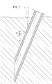
- FIG. 4 is a partial view showing a state in which the puncture needle 10 according to one embodiment of the present invention is inserted into the catheter 14 and the distal end portion including the blade surface 11 of the puncture needle 10 is exposed (protruded) from the distal end portion of the catheter 14.
- the inner diameter of the catheter 14 is set to be approximately the same as or slightly larger than the outer diameter of the raised portion 26 so that the puncture needle 10 provided with the raised portion 26 can be inserted.
- the inner circumferential groove portion 20 and the concavo-convex portion 22 are such that the distal end portion of the puncture needle 10 is exposed from the distal end portion of the catheter 14 by a predetermined length.
- the phase in the axial direction of the plurality of inner peripheral groove portions 20 and the phase in the axial direction of the plurality of concavo-convex portions 22 are formed so as to deviate from each other.
- the indwelling needle 12 including the puncture needle 10 according to the present embodiment is basically configured as described above. Next, the method of use and the effects thereof will be described.
- a syringe 30 Prior to the puncture of the indwelling needle 12, a syringe 30 is connected to the proximal end portion of the inner needle hub 18, as shown in FIG.
- the syringe 30 includes a cylindrical syringe body 32 and a plunger 34 inserted into the syringe body 32.
- a connection port 36 is provided at the distal end portion of the syringe body 32, and this connection port 36 is connected to the proximal end portion of the inner needle hub 18.
- the syringe 30 communicates with the inside of the inner needle hub 18 via the connection port 36.
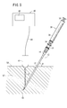
- the indwelling needle 12 In order to puncture the indwelling needle 12, first, as shown in FIG. 5, a medical staff such as a doctor holds the indwelling needle 12 including the puncture needle 10 and punctures it toward the blood vessel (vein) of the patient 50, By gradually inserting the puncture needle 10 toward the desired site, the tip of the puncture needle 10 advances while opening the body tissue 52. At this time, as shown in FIG. 6, the puncture needle 10 is inserted into the catheter 14, and in this state, the concavo-convex portion 22 of the puncture needle 10 is located inside the catheter 14. For this reason, the indentation needle 12 is punctured without the uneven
- FIG. 5 a medical staff such as a doctor holds the indwelling needle 12 including the puncture needle 10 and punctures it toward the blood vessel (vein) of the patient 50, By gradually inserting the puncture needle 10 toward the desired site, the tip of the puncture needle 10 advances while
- the probe 42 of the ultrasonic imaging device 40 is pressed against the vicinity of the puncture site of the patient 50 to irradiate an echo beam (ultrasound) E.
- the probe 42 is configured to transmit an echo beam E and receive a reflected wave (reflected echo) of the echo beam E.
- the echo beam E is transmitted from the skin surface of the patient 50 toward the inside, and is applied to the distal end portion of the indwelling needle 12. Then, as shown in FIG. 6, the echo beam E is reflected to the probe 42 side by the inner wall surface of the inner circumferential groove portion 20 formed on the inner circumferential surface of the catheter 14 and sealed inside the inner circumferential groove portion 20. It is also reflected by the air that is being applied.
- the ultrasonic wave (reflected wave) reflected by the inner circumferential groove 20 is shown as a reflected echo E1.
- the reflected echo E1 reflected by the inner wall surface of the inner circumferential groove portion 20 is not attenuated by the air in the inner circumferential groove portion 20, and has an intensity substantially equal to the intensity of the irradiated echo beam E.
- the reflected echo E1 is received by the probe 42.
- the echo beam E passes through the catheter 14 and is reflected to the probe 42 side at the concavo-convex portion 22.
- the ultrasonic wave reflected by the uneven portion 22 is shown as a reflection echo E2.
- the reflection echo E ⁇ b> 2 reflected by the concavo-convex portion 22 includes a reflection component by the groove portion 24 and a reflection component by the raised portion 26.
- the reflected echo E ⁇ b> 2 reflected by the uneven portion 22 is received by the probe 42.
- the groove portion 24 is formed in an arc shape in cross section
- the inner wall surface forms an arc-shaped reflection surface
- the raised portion 26 is formed in an arc shape in cross section, and the outer wall surface thereof. Constitutes an arcuate reflecting surface. Therefore, even when the puncture angle ⁇ (see FIG. 5) of the indwelling needle 12 is changed, the echo beam E transmitted from the probe 42 by the inner wall surface of the groove portion 24 and the outer wall surface of the raised portion 26 is directed to the probe 42 side. It becomes possible to reflect toward.
- the received data is output from the probe 42 to the control unit (not shown) of the ultrasonic imaging apparatus 40 through the lead wire 44.
- the images of the catheter 14 and the puncture needle 10 displayed on the display 46 are displayed linearly by the length along the axial direction of the concavo-convex portion 22 detected by the ultrasonic imaging device 40. It can be confirmed from the display 46 whether or not the tip has reached the blood vessel (vein) of the patient 50.
- the vicinity of the tip of the puncture needle 10 is clearly displayed as an image on the display 46 of the ultrasonic imaging apparatus 40, and the position of the puncture needle 10 constituting the indwelling needle 12 is confirmed with high accuracy.
- the doctor or the like moves the puncture needle 10 and the probe 42 while confirming the display 46, and guides the puncture needle 10 to the blood vessel of the patient 50.
- the indwelling needle 12 is advanced while appropriately pulling the plunger 34 of the syringe 30.
- the catheter 14 was left, the puncture needle 10 and the syringe 30 were removed, and a guide wire (not shown) was inserted into the blood vessel via the catheter 14. Later, the catheter 14 is removed. Next, a central venous catheter (not shown) is placed in the blood vessel along the guide wire. Next, an infusion line (not shown) is connected to the central artery catheter to supply nutrients, chemicals, and the like into the blood vessel.
- the puncture needle 10 When the puncture needle 10 is removed while leaving the catheter 14, the puncture needle 10 is removed from the patient's body through the inside (lumen) of the catheter 14. The uneven portion 22 does not contact the body tissue 52.
- the uneven portion 22 includes the groove portion 24 and the raised portions 26 provided on both sides thereof, so that the ultrasonic wave is not only the groove portion 24 but also the raised portion. 26 also reflects. Accordingly, it is possible to reliably and suitably reflect the ultrasonic wave and detect it by the ultrasonic imaging apparatus 40. As a result, the puncture needle 10 punctured by the patient can be confirmed reliably and with high accuracy by the ultrasonic imaging device 40, and a safe and reliable procedure can be performed while confirming the position of the puncture needle 10. .
- the concavo-convex portion 22 is formed in an annular shape, the entire circumference serves as a reflection surface, and effectively reflects ultrasonic waves regardless of the position around the axis of the puncture needle 10 at the time of puncture. It becomes possible to make it.
- the concavo-convex portions 22 in the axial direction of the puncture needle 10, more portions that appropriately reflect ultrasonic waves are provided accordingly. Therefore, it is possible to effectively reflect the ultrasonic wave and obtain a more sufficient reflected wave. As a result, the position of the puncture needle 10 can be confirmed with higher accuracy by the ultrasonic imaging apparatus 40.
- the groove portion 24 is formed in an arc shape in cross section, its inner wall surface forms an arc-shaped reflection surface, and the raised portion 26 is formed in an arc shape in cross section, and its outer wall surface is in an arc shape.
- the reflective surface is configured. Therefore, even when the puncture angle ⁇ (see FIG. 5) of the indwelling needle 12 is changed, the ultrasonic waves transmitted from the probe 42 by the inner wall surface of the groove 24 and the outer wall surface of the raised portion 26 are directed toward the probe 42 side. Can be reflected. In other words, regardless of the puncture angle ⁇ of the indwelling needle 12, the ultrasonic wave can be reflected toward the probe 42 and the position of the indwelling needle 12 can be confirmed.
- the inner circumferential groove portion 20 is formed on the inner circumferential surface of the catheter 14 and the ultrasonic waves are reflected also in the inner circumferential groove portion 20, the intensity of the reflected wave received by the probe 42 can be increased, and the clearer An echo image is obtained, and as a result, the position of the distal end portion of the indwelling needle 12 can be confirmed with high accuracy.
- the puncture needle 10 of this invention is a figure.
- the present invention can also be used when a puncture needle 10 is directly punctured into a patient to secure a blood vessel without using the catheter 14.
- a Y hub (not shown) is connected to the proximal end portion of the inner needle hub 18, and a guide wire and a central artery catheter are passed through the Y hub, the inner needle hub 18 and the puncture needle 10 in the same manner as described above. It is possible to perform the procedure.
- the ultrasonic wave (echo beam E) is reliably and suitably reflected by the concave and convex portion 22, and the puncture needle 10 punctured by the patient is confirmed surely and with high accuracy by the ultrasonic imaging device 40.
- a safe and reliable procedure can be performed while confirming the position of the puncture needle 10.
- the puncture needle 10 has been described as a guide wire introduction needle used when a central artery catheter is indwelled by the Seldinger method, the puncture needle 10 of the present invention is erased. It can also be used as an indwelling needle used for infusion by indwelling in a blood vessel, a biopsy needle used for collecting a part of living tissue or cells, and the like.
- FIG. 8 is a side configuration diagram showing the distal end portion of the ultrasonic guide puncture needle 10a (hereinafter simply referred to as “puncture needle 10a”) according to the first modification and the vicinity thereof.
- the plurality of uneven portions 22 may be formed so that the raised portions 26 of the adjacent uneven portions 22 are continuous (connected).
- the concave and convex portion 22 of the puncture needle 10 continuously, it is possible to increase the amount of reflected waves toward the probe 42 compared to the puncture needle 10 according to the basic shape described above. Become.
- the position of the puncture needle 10a can be confirmed with higher accuracy by the ultrasonic imaging apparatus 40.
- FIG. 9 is a side configuration diagram showing the distal end portion of the ultrasonic guide puncture needle 10b (hereinafter simply referred to as “puncture needle 10b”) according to the second modified example and the vicinity thereof.
- the uneven portion 27 having the groove portion 28 and the raised portions 29 provided on both sides of the groove portion 28 circulates at least a plurality of times on the outer peripheral surface of the puncture needle 10b. It may be formed in a spiral shape extending in the axial direction.
- the concavo-convex portion 27 configured in this manner, it is possible to effectively reflect the ultrasonic wave and obtain a more sufficient reflected wave, similarly to the concavo-convex portion 22 described above. As a result, the position of the puncture needle 10b can be confirmed with higher accuracy by the ultrasonic imaging apparatus 40.
- the concavo-convex portion 27 of the puncture needle 10b is formed in a spiral shape, the phase in the axial direction of the plurality of inner peripheral groove portions 20 and the phase in the axial direction of the concavo-convex portions 27 when inserted into the catheter 14 It becomes easy to shift each other.
- the axis of the inner circumferential groove 20 can also be formed by forming the inner circumferential groove 20 of the catheter 14 in a spiral having an angle different from that of the concave / convex 27 or a spiral in a direction different from that of the concave / convex 27. It is easy to shift the phase of the direction and the phase of the concavo-convex portion 27 in the axial direction.
- phase in the axial direction of the inner circumferential groove 20 and the phase in the axial direction of the concavo-convex portion 27 are shifted from each other, it is possible to suppress the attenuation of the reflection intensity of the ultrasonic waves.
Landscapes
- Health & Medical Sciences (AREA)
- Vascular Medicine (AREA)
- Engineering & Computer Science (AREA)
- Anesthesiology (AREA)
- Biomedical Technology (AREA)
- Heart & Thoracic Surgery (AREA)
- Hematology (AREA)
- Life Sciences & Earth Sciences (AREA)
- Animal Behavior & Ethology (AREA)
- General Health & Medical Sciences (AREA)
- Public Health (AREA)
- Veterinary Medicine (AREA)
- Infusion, Injection, And Reservoir Apparatuses (AREA)
- Ultra Sonic Daignosis Equipment (AREA)
- Media Introduction/Drainage Providing Device (AREA)
Abstract
La présente invention concerne une aiguille (10) de ponction à guidage ultrasonore qui constitue l'aiguille interne d'une aiguille (12) à demeure, et qui possède des parties concavo-convexes (22) sur lesquelles les ultrasons sont réfléchis. Les parties concavo-convexes (22) sont équipées : d'une partie rainure (24) agencée sur la surface périphérique externe à proximité de la partie extrémité avant qui possède une surface incisive (11), et de parties en saillie (26) agencées des deux côtés de la partie rainure (24).
Priority Applications (4)
| Application Number | Priority Date | Filing Date | Title |
|---|---|---|---|
| JP2011547387A JP5802135B2 (ja) | 2009-12-21 | 2010-11-01 | 超音波ガイド穿刺針及び留置針 |
| CN201080046771.4A CN103732273B (zh) | 2009-12-21 | 2010-11-01 | 超声波导向穿刺针及留置针 |
| EP10839073.3A EP2517745B1 (fr) | 2009-12-21 | 2010-11-01 | Aiguille de ponction et aiguille à demeure à guidage ultrasonore |
| US13/515,403 US9592352B2 (en) | 2009-12-21 | 2010-11-01 | Ultrasound-guided piercing needle and indwelling needle |
Applications Claiming Priority (2)
| Application Number | Priority Date | Filing Date | Title |
|---|---|---|---|
| JP2009-289598 | 2009-12-21 | ||
| JP2009289598 | 2009-12-21 |
Publications (1)
| Publication Number | Publication Date |
|---|---|
| WO2011077837A1 true WO2011077837A1 (fr) | 2011-06-30 |
Family
ID=44195382
Family Applications (1)
| Application Number | Title | Priority Date | Filing Date |
|---|---|---|---|
| PCT/JP2010/069401 WO2011077837A1 (fr) | 2009-12-21 | 2010-11-01 | Aiguille de ponction et aiguille à demeure à guidage ultrasonore |
Country Status (5)
| Country | Link |
|---|---|
| US (1) | US9592352B2 (fr) |
| EP (1) | EP2517745B1 (fr) |
| JP (1) | JP5802135B2 (fr) |
| CN (1) | CN103732273B (fr) |
| WO (1) | WO2011077837A1 (fr) |
Cited By (2)
| Publication number | Priority date | Publication date | Assignee | Title |
|---|---|---|---|---|
| JP2016508797A (ja) * | 2013-02-26 | 2016-03-24 | アレン メーズ, | カラー超音波針 |
| JP2019531793A (ja) * | 2016-08-31 | 2019-11-07 | ソンウォン メディカル シーオー., エルティーディーSungwon Medical Co., Ltd | 超音波生検ガイド画像の視認性のための施術用強化細針 |
Families Citing this family (16)
| Publication number | Priority date | Publication date | Assignee | Title |
|---|---|---|---|---|
| EP2967500B1 (fr) | 2013-03-14 | 2019-09-25 | Muffin Incorporated | Surfaces échogènes avec formation de fossettes pressées |
| CN105530979A (zh) * | 2013-09-11 | 2016-04-27 | 泰尔茂株式会社 | 医疗用的中空针组装体以及中空针的制造方法 |
| US9993263B2 (en) | 2013-12-12 | 2018-06-12 | Catalin Esanu | Method and device for ultrasound guided minimal invasive access of a bodily cavity |
| US9980699B2 (en) * | 2014-09-12 | 2018-05-29 | Cook Medical Technologies Llc | Shaped echogenic needle groove |
| CN104688303B (zh) * | 2015-02-15 | 2017-04-12 | 扬州市江洲医疗器械有限公司 | 无损伤硬膜外导管穿刺针 |
| CN104971406A (zh) * | 2015-05-22 | 2015-10-14 | 南京农业大学 | 一种表面具有微反射器结构的医学用针及其制备方法 |
| EP4074265A1 (fr) * | 2015-10-26 | 2022-10-19 | Smiths Medical ASD, Inc. | Aiguille échogène |
| CA3001647A1 (fr) * | 2015-10-26 | 2017-06-01 | Smiths Medical International Limited | Ensembles aiguille echogene et leur procede d'utilisation |
| USD842984S1 (en) * | 2015-12-09 | 2019-03-12 | Dentsply Ih Ab | Catheter |
| WO2018118817A1 (fr) | 2016-12-19 | 2018-06-28 | New World Medical, Inc. | Dispositifs de traitement oculaire et procédés d'utilisation associés |
| RU2658475C1 (ru) * | 2017-06-09 | 2018-06-21 | Антон Александрович Касаткин | Пункционная игла |
| CN107569258A (zh) * | 2017-09-29 | 2018-01-12 | 上海长海医院 | 一种穿刺针 |
| CN110025872A (zh) * | 2018-01-12 | 2019-07-19 | 美敦力公司 | 一种增强超声下显影性的球囊扩张导管 |
| WO2020148938A1 (fr) * | 2019-01-17 | 2020-07-23 | 富士フイルム株式会社 | Aiguille de ponction, dispositif d'examen a ultra-sons et procede de commande d'appareil d'examen a ultra-sons |
| WO2020186419A1 (fr) * | 2019-03-18 | 2020-09-24 | 王沁 | Aiguille de ponction ayant une poignée |
| CN112137691B (zh) * | 2019-06-27 | 2023-07-21 | 上海安久生物科技有限公司 | 一种制备超声引导穿刺针的系统 |
Citations (5)
| Publication number | Priority date | Publication date | Assignee | Title |
|---|---|---|---|---|
| JPH03228748A (ja) | 1990-02-02 | 1991-10-09 | Ogura Hisako | 超音波反射体 |
| JPH10248793A (ja) * | 1997-03-14 | 1998-09-22 | Olympus Optical Co Ltd | 処置具 |
| JP3171525B2 (ja) | 1994-04-14 | 2001-05-28 | 康雄 真島 | 医療用穿刺針 |
| WO2007013130A1 (fr) * | 2005-07-25 | 2007-02-01 | Hakko Co., Ltd. | Aiguille de perçage à ultrasons |
| JP3890013B2 (ja) * | 2002-12-05 | 2007-03-07 | オリンパス株式会社 | 超音波用穿刺針 |
Family Cites Families (9)
| Publication number | Priority date | Publication date | Assignee | Title |
|---|---|---|---|---|
| DE2425724C3 (de) * | 1974-05-28 | 1979-09-27 | Siemens Ag, 1000 Berlin Und 8000 Muenchen | Punktionskanüle |
| US4401124A (en) * | 1981-08-13 | 1983-08-30 | Technicare Corporation | Reflection enhancement of a biopsy needle |
| US4582061A (en) * | 1981-11-18 | 1986-04-15 | Indianapolis Center For Advanced Research, Inc. | Needle with ultrasonically reflective displacement scale |
| US5490521A (en) * | 1993-08-31 | 1996-02-13 | Medtronic, Inc. | Ultrasound biopsy needle |
| US20060047254A1 (en) * | 2003-04-04 | 2006-03-02 | Ravi Nallakrishnan | Phacoemulsification needle |
| DE202005008489U1 (de) * | 2005-05-31 | 2005-09-08 | Medi-Globe Gmbh | Medizinische Vorrichtung, die mittels Ultraschall sichtbar zu machen ist |
| US7682337B2 (en) * | 2007-02-07 | 2010-03-23 | Cook Incorporated | Method and apparatus for gaining percutaneous access to a body |
| JP5108580B2 (ja) * | 2008-03-26 | 2012-12-26 | テルモ株式会社 | 留置針 |
| US9521993B2 (en) * | 2008-12-30 | 2016-12-20 | Boston Scientific Scimed, Inc. | Echogenic enhancement for a needle |
-
2010
- 2010-11-01 EP EP10839073.3A patent/EP2517745B1/fr active Active
- 2010-11-01 CN CN201080046771.4A patent/CN103732273B/zh active Active
- 2010-11-01 WO PCT/JP2010/069401 patent/WO2011077837A1/fr active Application Filing
- 2010-11-01 US US13/515,403 patent/US9592352B2/en active Active
- 2010-11-01 JP JP2011547387A patent/JP5802135B2/ja active Active
Patent Citations (5)
| Publication number | Priority date | Publication date | Assignee | Title |
|---|---|---|---|---|
| JPH03228748A (ja) | 1990-02-02 | 1991-10-09 | Ogura Hisako | 超音波反射体 |
| JP3171525B2 (ja) | 1994-04-14 | 2001-05-28 | 康雄 真島 | 医療用穿刺針 |
| JPH10248793A (ja) * | 1997-03-14 | 1998-09-22 | Olympus Optical Co Ltd | 処置具 |
| JP3890013B2 (ja) * | 2002-12-05 | 2007-03-07 | オリンパス株式会社 | 超音波用穿刺針 |
| WO2007013130A1 (fr) * | 2005-07-25 | 2007-02-01 | Hakko Co., Ltd. | Aiguille de perçage à ultrasons |
Non-Patent Citations (1)
| Title |
|---|
| See also references of EP2517745A4 * |
Cited By (2)
| Publication number | Priority date | Publication date | Assignee | Title |
|---|---|---|---|---|
| JP2016508797A (ja) * | 2013-02-26 | 2016-03-24 | アレン メーズ, | カラー超音波針 |
| JP2019531793A (ja) * | 2016-08-31 | 2019-11-07 | ソンウォン メディカル シーオー., エルティーディーSungwon Medical Co., Ltd | 超音波生検ガイド画像の視認性のための施術用強化細針 |
Also Published As
| Publication number | Publication date |
|---|---|
| CN103732273B (zh) | 2017-03-29 |
| US9592352B2 (en) | 2017-03-14 |
| CN103732273A (zh) | 2014-04-16 |
| JPWO2011077837A1 (ja) | 2013-05-02 |
| JP5802135B2 (ja) | 2015-10-28 |
| EP2517745A1 (fr) | 2012-10-31 |
| EP2517745A4 (fr) | 2013-06-05 |
| US20120253297A1 (en) | 2012-10-04 |
| EP2517745B1 (fr) | 2019-01-02 |
Similar Documents
| Publication | Publication Date | Title |
|---|---|---|
| JP5802135B2 (ja) | 超音波ガイド穿刺針及び留置針 | |
| JP2011125632A (ja) | 超音波ガイド穿刺針及び留置針 | |
| US8523841B2 (en) | Catheter with spiral slit terminating in slit termination portion oriented to suppress crack occurrence | |
| JP2011125389A (ja) | 留置針 | |
| JP6322210B2 (ja) | 標的化された挿管のためのデバイス、システム、および方法 | |
| JP3171525B2 (ja) | 医療用穿刺針 | |
| AU2009276280A1 (en) | An echogenic medical needle | |
| JP5552050B2 (ja) | 留置針 | |
| JP2011120760A (ja) | 留置針 | |
| JP5191823B2 (ja) | 留置針及び穿刺針 | |
| JP5171355B2 (ja) | 生体内挿入用プローブ装置 | |
| JP6591987B2 (ja) | 医療用デバイス | |
| JP6475367B2 (ja) | 挿入物及びアタッチメント部材 | |
| JP2009028253A (ja) | ニードルアセンブリ | |
| JP6884538B2 (ja) | 接続ポートおよび医療用デバイス | |
| JP2020127607A (ja) | 埋込体留置具及び埋込体 | |
| JP5634667B2 (ja) | 留置針及びその製造方法 | |
| JP7231639B2 (ja) | 穿刺針 | |
| US11517667B2 (en) | Puncture needle | |
| JP2022149295A (ja) | 送達デバイス | |
| JP2014033722A (ja) | 医療用デバイス |
Legal Events
| Date | Code | Title | Description |
|---|---|---|---|
| 121 | Ep: the epo has been informed by wipo that ep was designated in this application |
Ref document number: 10839073 Country of ref document: EP Kind code of ref document: A1 |
|
| WWE | Wipo information: entry into national phase |
Ref document number: 2011547387 Country of ref document: JP |
|
| WWE | Wipo information: entry into national phase |
Ref document number: 13515403 Country of ref document: US |
|
| WWE | Wipo information: entry into national phase |
Ref document number: 2010839073 Country of ref document: EP |
|
| NENP | Non-entry into the national phase |
Ref country code: DE |