WO2011065495A1 - 制御装置及び制御方法 - Google Patents
制御装置及び制御方法 Download PDFInfo
- Publication number
- WO2011065495A1 WO2011065495A1 PCT/JP2010/071150 JP2010071150W WO2011065495A1 WO 2011065495 A1 WO2011065495 A1 WO 2011065495A1 JP 2010071150 W JP2010071150 W JP 2010071150W WO 2011065495 A1 WO2011065495 A1 WO 2011065495A1
- Authority
- WO
- WIPO (PCT)
- Prior art keywords
- power
- storage battery
- operation mode
- rate
- charge
- Prior art date
Links
Images


Classifications
-
- H—ELECTRICITY
- H02—GENERATION; CONVERSION OR DISTRIBUTION OF ELECTRIC POWER
- H02J—CIRCUIT ARRANGEMENTS OR SYSTEMS FOR SUPPLYING OR DISTRIBUTING ELECTRIC POWER; SYSTEMS FOR STORING ELECTRIC ENERGY
- H02J3/00—Circuit arrangements for ac mains or ac distribution networks
- H02J3/28—Arrangements for balancing of the load in a network by storage of energy
- H02J3/32—Arrangements for balancing of the load in a network by storage of energy using batteries with converting means
-
- H—ELECTRICITY
- H01—ELECTRIC ELEMENTS
- H01M—PROCESSES OR MEANS, e.g. BATTERIES, FOR THE DIRECT CONVERSION OF CHEMICAL ENERGY INTO ELECTRICAL ENERGY
- H01M10/00—Secondary cells; Manufacture thereof
- H01M10/42—Methods or arrangements for servicing or maintenance of secondary cells or secondary half-cells
- H01M10/44—Methods for charging or discharging
-
- H—ELECTRICITY
- H01—ELECTRIC ELEMENTS
- H01M—PROCESSES OR MEANS, e.g. BATTERIES, FOR THE DIRECT CONVERSION OF CHEMICAL ENERGY INTO ELECTRICAL ENERGY
- H01M10/00—Secondary cells; Manufacture thereof
- H01M10/42—Methods or arrangements for servicing or maintenance of secondary cells or secondary half-cells
- H01M10/46—Accumulators structurally combined with charging apparatus
- H01M10/465—Accumulators structurally combined with charging apparatus with solar battery as charging system
-
- H—ELECTRICITY
- H01—ELECTRIC ELEMENTS
- H01M—PROCESSES OR MEANS, e.g. BATTERIES, FOR THE DIRECT CONVERSION OF CHEMICAL ENERGY INTO ELECTRICAL ENERGY
- H01M10/00—Secondary cells; Manufacture thereof
- H01M10/42—Methods or arrangements for servicing or maintenance of secondary cells or secondary half-cells
- H01M10/48—Accumulators combined with arrangements for measuring, testing or indicating the condition of cells, e.g. the level or density of the electrolyte
-
- H—ELECTRICITY
- H01—ELECTRIC ELEMENTS
- H01M—PROCESSES OR MEANS, e.g. BATTERIES, FOR THE DIRECT CONVERSION OF CHEMICAL ENERGY INTO ELECTRICAL ENERGY
- H01M2220/00—Batteries for particular applications
- H01M2220/10—Batteries in stationary systems, e.g. emergency power source in plant
-
- Y—GENERAL TAGGING OF NEW TECHNOLOGICAL DEVELOPMENTS; GENERAL TAGGING OF CROSS-SECTIONAL TECHNOLOGIES SPANNING OVER SEVERAL SECTIONS OF THE IPC; TECHNICAL SUBJECTS COVERED BY FORMER USPC CROSS-REFERENCE ART COLLECTIONS [XRACs] AND DIGESTS
- Y02—TECHNOLOGIES OR APPLICATIONS FOR MITIGATION OR ADAPTATION AGAINST CLIMATE CHANGE
- Y02E—REDUCTION OF GREENHOUSE GAS [GHG] EMISSIONS, RELATED TO ENERGY GENERATION, TRANSMISSION OR DISTRIBUTION
- Y02E60/00—Enabling technologies; Technologies with a potential or indirect contribution to GHG emissions mitigation
- Y02E60/10—Energy storage using batteries
Definitions
- the present invention provides a control device for controlling the storage battery and the heat accumulator provided in a consumer of electric power having a DC power supply, a load, and a storage battery capable of storing electric power from the DC power supply, and the control device It relates to a control method.
- the conventional technology described above does not take into consideration the power demand of the consumer group and the power supply of the power system. For this reason, there was a problem that reverse power flow from the storage battery in the consumer to the power system is performed even when the power supply of the power system is excessive with respect to the power demand of the consumer group.
- an object of the present invention is to provide a control device and a control method that enable appropriate storage battery control in consideration of power demand and power supply.
- the first feature of the present invention is a power having a DC power source (solar cell 106), a load (lighting 110, an air conditioner 112), and a storage battery (storage battery 108) capable of storing power from the DC power source.
- a control device (smart controller 102) that is provided in a consumer (smart house 10) and controls the storage battery, and receives charge information indicating a power charge determined according to the demand and supply of power (Reception processing unit 162) and a storage battery control unit (storage battery control unit 164) that controls charging and discharging of the storage battery of the consumer based on the fee information received by the receiving unit.
- a control device that is provided in a consumer (smart house 10) and controls the storage battery, and receives charge information indicating a power charge determined according to the demand and supply of power (Reception processing unit 162) and a storage battery control unit (storage battery control unit 164) that controls charging and discharging of the storage battery of the consumer based on the fee information received by the receiving unit.
- Such a control device controls charging and discharging of a storage battery of a consumer based on rate information indicating the power rate in view of the fact that the power rate is determined according to the demand and supply of power. For this reason, appropriate storage battery control in consideration of power demand and power supply becomes possible.
- a second feature of the present invention is that the storage battery control unit performs control to charge the storage battery with power from an electric power system when the power rate indicated by the rate information is lower than a first reference value.
- the gist performs control to charge the storage battery with power from an electric power system when the power rate indicated by the rate information is lower than a first reference value.
- a third feature of the present invention includes a heat storage device (heat storage device 114) that converts electric power into heat, and the storage battery control unit is configured such that when the power rate indicated by the rate information is lower than a second reference value, The gist is to perform control to supply power from the power system to the regenerator.
- heat storage device 114 heat storage device that converts electric power into heat
- the storage battery control unit is configured such that when the power rate indicated by the rate information is lower than a second reference value, The gist is to perform control to supply power from the power system to the regenerator.
- the gist of a fourth feature of the present invention is that the storage battery control unit performs control to discharge the storage battery when the power rate indicated by the rate information is higher than a third reference value.
- a fifth feature of the present invention is that the storage battery control unit controls reverse flow from the storage battery to the power system when the power rate indicated by the rate information is higher than a fourth reference value.
- an operation mode related to the storage battery is associated with a threshold value of a power charge
- the storage battery control unit includes a power charge indicated by the charge information, a threshold value of the power charge, Based on the above, the gist is to select the operation mode.
- a seventh feature of the present invention is that the storage battery control unit is a case where the selected operation mode is a mode for discharging the storage battery, and the remaining amount of power of the storage battery is a predetermined value or less, and the direct current The gist is to stop the discharge control of the storage battery when at least one of the prediction that the power generation amount of the power source is reduced and the prediction that the power consumption of the load is increased is satisfied.
- the eighth feature of the present invention is summarized in that the charge information indicates at least one of a predetermined power charge and a current power charge.
- the receiving unit receives the charge information indicating the predetermined power charge in a first period, and receives the charge information indicating the current power charge from the first period.
- the main point is to receive in a short second cycle.
- an operation mode related to the storage battery is associated with a threshold value of a power charge
- the storage battery control unit is configured to receive the charge information indicating the current power charge by the receiving unit.
- the gist is to select the operation mode based on the current power rate and the threshold value of the power rate during reception in the second period.
- An eleventh feature of the present invention is a control method in a control device for controlling a storage battery provided in a consumer of power having a DC power supply, a load, and a storage battery capable of storing power from the DC power supply.
- the control device receives rate information indicating a power rate determined according to the demand and supply of power, and the control device receives the consumer based on the received rate information. And a step of controlling charging and discharging of the storage battery of the present invention.
- FIG. 1 is a configuration diagram of a power system according to an embodiment of the present invention.
- FIG. 2 is a configuration diagram of the smart controller according to the embodiment of the present invention.
- FIG. 3 is a diagram illustrating a correspondence relationship between the operation mode and the charge threshold according to the embodiment of the present invention.
- FIG. 4 is a diagram illustrating a time transition of the power rate according to the embodiment of the present invention.
- FIG. 5 is a flowchart showing the operation of the smart controller according to the embodiment of the present invention.
- FIG. 1 is a configuration diagram of a power system 1 according to an embodiment of the present invention.
- the power system 1 shown in FIG. 1 is a system that employs a so-called smart grid.
- the power system 1 includes a smart house 10 that is a power consumer, a generator 50 that is a power supplier, and an energy management system (EMS) that performs overall power control of the power system 1.
- EMS energy management system
- a plurality of smart houses 10 exist under the power grid 60, and the plurality of smart houses 10 form a power consumer group.
- power is transmitted from the generator 50 to the smart house 10 via the power system 60, and power is used in the smart house 10.
- a reverse power flow from the smart house 10 to the power system 60 is performed as appropriate.
- the power consumption is measured in the smart house 10 and sent to the EMS 70 via the Internet 80 as measurement data.
- the EMS70 determines the electric power charge based on the electric power supply of the electric power grid
- the EMS 70 decreases the power rate as the value (supply / demand difference) obtained by subtracting the amount of power used in the customer group from the suppliable amount of power from the power system 60 to the customer group decreases, and as the supply / demand difference decreases. , Raise the electricity bill.
- the EMS 70 uses TOU (Time of Use), which is a power rate predetermined for each time zone based on a past supply-demand difference, and RTP (Real Time), which is a power rate determined based on a real-time supply-demand difference. Pricing) can be determined.
- TOU Time of Use
- RTP Real Time
- the EMS 70 transmits control information including rate information indicating the determined power rate to the smart house 10 via the Internet 80. Specifically, the EMS 70 transmits the TOU, for example, in a 24-hour cycle, for a predetermined period (for example, one day) before the time zone to which the TOU is applied, and the RTP is transmitted in advance of the TOU transmission cycle. Transmit in a short cycle (for example, a cycle of 10 minutes).
- the smart house 10 includes a smart controller 102 as a control device, a smart meter 103, a hybrid power conditioner (hybrid PCS) 104, a solar battery 106 as a DC power source, a storage battery 108, a remote control sensor unit 109, a load As the lighting 110 and the air conditioner 112, and a heat storage device 114 as a heat storage device.
- a smart controller 102 as a control device
- a smart meter 103 includes a smart meter 103, a hybrid power conditioner (hybrid PCS) 104, a solar battery 106 as a DC power source, a storage battery 108, a remote control sensor unit 109, a load As the lighting 110 and the air conditioner 112, and a heat storage device 114 as a heat storage device.
- hybrid PCS hybrid power conditioner
- the smart controller 102 is connected to the Internet 80 via a wide area communication line 90 which is a wired line or a wireless line.
- the smart controller 102 connects the smart meter 103, the hybrid PCS 104, and the remote control sensor unit 109 via a home communication line 160 that is a wired line or a wireless line.
- the configuration and operation of the smart controller 102 will be described later.
- the smart meter 103 is connected to the power grid 60 and to the home distribution line 150.
- the smart meter 103 detects the amount of power supplied from the power system 60 and used for the operation of the lighting 110, the air conditioner 112, and the heat storage device 114, and for charging the storage battery 108, and the EMS 70 via the Internet 80 as measurement data. Send to.
- the hybrid PCS 104 is connected to the domestic distribution line 150 and to the solar battery 106 and the storage battery 108.
- the hybrid PCS 104 sends the DC power generated by the solar battery 106 to the domestic distribution line 150 or stores it in the storage battery 108 under the control of the smart controller 102.
- the hybrid PCS 104 converts the DC power generated by the discharge of the storage battery 108 into AC power according to the control of the smart controller 102 and sends it to the home distribution line 150.
- the AC power sent to the home distribution line 150 is appropriately used in the lighting 110, the air conditioner 112, and the heat storage device 114, or becomes reverse power flow to the power system 60.
- the hybrid PCS 104 converts the AC power from the power system 60 into DC power in accordance with the control of the smart controller 102 and then stores it in the storage battery 108.
- the lighting 110, the air conditioner 112, and the heat storage device 114 are connected to the home distribution line 150 and to the home communication line 160.
- the lighting 110, the air conditioner 112, and the heat storage device 114 are operated by AC power from the home distribution line 150 in accordance with the control of the smart controller 102.
- the heat storage device 114 is, for example, a heat pump.
- FIG. 2 is a configuration diagram of the smart controller 102.
- the smart controller 102 includes a control unit 152, a storage unit 153, and a communication unit 154.
- the control unit 152 is, for example, a CPU, and controls each unit in the smart house 10.
- the storage unit 153 is configured by a memory, for example, and stores various information used for controlling each unit in the smart house 10.
- the communication unit 154 receives control information from the EMS 70 via the wide area communication line 90 and the Internet 80.
- the communication unit 154 communicates with the smart meter 103, the hybrid PCS 104, and the remote control sensor unit 109 via the home communication line 160.
- the control unit 152 includes a reception processing unit 162 and a storage battery control unit 164.
- the reception processing unit 162 inputs control information received by the communication unit 154. Further, the reception processing unit 162 extracts fee information included in the control information.
- the storage battery control unit 164 determines the operation mode of the storage battery 108 by comparing the power charge indicated by the extracted charge information with a predetermined power charge threshold (charge threshold).
- charge threshold a predetermined power charge threshold
- the operation mode is
- the operation mode is associated with charging and discharging of the storage battery 108. That is, the storage battery 108 is charged or discharged according to the set operation mode.
- the storage battery control unit 164 determines the operation mode by comparing the RTP and the charge threshold while acquiring RTP at a predetermined transmission cycle, and acquires RTP at a predetermined transmission cycle due to a communication failure or the like. While this is not possible, the operation mode is determined by comparing the RTP with the charge threshold.
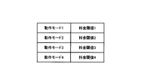
- FIG. 3 is a diagram showing the correspondence between operation modes and charge thresholds.
- the operation mode and the charge threshold have a correspondence relationship that the charge threshold corresponding to the charging operation mode is low and the charge threshold corresponding to the discharge operation mode is high.
- the charge threshold increases as the number increases.
- operation mode 1 and operation mode 2 are operation modes in which the storage battery 108 is charged
- operation mode 3 and operation mode 4 are operation modes in which the storage battery 108 is discharged.
- the operation mode 1 is an operation mode in which the storage battery 108 is charged by the electric power from the power system 60 and the heat storage device 114 stores heat
- the operation mode 2 is an operation mode 2 in which the storage battery 108 is charged by the electric power from the power system 60.
- the operation mode for charging, the operation mode 3 is for discharging the storage battery 108 and supplying the power to the lighting 110 and the air conditioner 112 as a load
- the operation mode 4 is for discharging the storage battery 108 and using the power as a load. This is an operation mode to be supplied to the lighting 110, the air conditioner 112, and the power system 60.
- the correspondence between the operation mode and the charge threshold is set in advance and stored in the storage unit 153.
- the storage battery control unit 164 reads the correspondence relationship between the operation mode and the charge threshold value from the storage unit 153. Next, the storage battery control unit 164 specifies a charge threshold that is higher than the power charge indicated by the extracted charge information and that is closest to the power charge indicated by the extracted charge information, among the charge thresholds.
- the storage battery control unit 164 specifies the rate threshold 3. Furthermore, the storage battery control unit 164 specifies an operation mode corresponding to the specified charge threshold. For example, when the charge threshold 3 is specified in FIG. 3, the operation mode 3 corresponding to the charge threshold 3 is further specified.
- the storage battery control unit 164 While the RTP is acquired at a predetermined cycle, the storage battery control unit 164 initially determines the operation mode of the storage battery 108 as the operation mode 1 because the RTP is less than the charge threshold value 1. When RTP becomes equal to or higher than the charge threshold value 1 at time t1, the storage battery control unit 164 switches the operation mode of the storage battery 108 from the operation mode 1 to the operation mode 2. When RTP becomes equal to or higher than the charge threshold value 2 at time t2, the storage battery control unit 164 switches the operation mode of the storage battery 108 from the operation mode 2 to the operation mode 3. When RTP becomes equal to or higher than the charge threshold 3 at time t3, the storage battery control unit 164 switches the operation mode of the storage battery 108 from the operation mode 3 to the operation mode 4.
- the storage battery control unit 164 switches the operation mode of the storage battery 108 from the operation mode 4 to the operation mode 3.
- RTP becomes less than charge threshold 2 at time t5 storage battery control unit 164 switches the operation mode of storage battery 108 from operation mode 3 to operation mode 2.
- RTP becomes less than the charge threshold value 1 at time t6 the storage battery control unit 164 switches the operation mode of the storage battery 108 from the operation mode 2 to the operation mode 1.
- the storage battery control unit 164 initially determines the operation mode of the storage battery 108 as the operation mode 1 because the TOU is less than the charge threshold value 1. To do. When TOU becomes equal to or higher than the charge threshold value 1 at time t11, the storage battery control unit 164 switches the operation mode of the storage battery 108 from the operation mode 1 to the operation mode 2. Thereafter, when the TOU becomes less than the charge threshold value 1 at time t21, the storage battery control unit 164 switches the operation mode of the storage battery 108 from the operation mode 2 to the operation mode 1.
- the operation mode of the storage battery 108 is determined as described above.
- the storage battery control unit 164 performs the following processing.
- the storage battery control unit 164 controls the hybrid PCS 104 to charge the storage battery 108 with the power from the power system 60. Furthermore, the storage battery control unit 116 controls the heat storage device 114 to cause the heat storage device 114 to store heat using the power from the power system 60. Further, when the determined operation mode is the operation mode 1, the storage battery control unit 164 controls the hybrid PCS 104 to charge the storage battery 108 with the power from the power system 60.
- the storage battery control unit 164 performs the following processing.
- the storage battery control unit 164 requests the remaining power of the storage battery 108 from the hybrid PCS 104 via the communication unit 154.
- the hybrid PCS 104 detects the remaining power in the storage battery 108 and outputs the remaining power to the smart controller 102.
- the storage battery control unit 164 inputs the remaining amount of power via the communication unit 154.
- the storage battery control unit 164 acquires prediction information on the future power generation amount of the solar battery 106. For example, if the night time zone is included in the period from the present to the predetermined time later, the storage battery control unit 164 indicates the prediction information that the power generation amount of the solar cell 106 in the period from the present to the predetermined time later decreases. obtain. In addition, the storage battery control unit 164 receives weather forecast information from an external site via the communication unit 154, the wide area communication line 90, and the Internet 80.
- the storage battery control unit 164 becomes rainy or cloudy in a period from the present to a predetermined time based on the information of the weather forecast, the power generation amount of the solar battery 106 in the period from the present to the predetermined time later Get prediction information that will decrease.
- the storage battery control unit 164 acquires predicted values of future power consumption of the lighting 110 and the air conditioner 112 as loads.
- the storage unit 153 stores a statistical value that is a value of power consumption of the illumination 110 and the air conditioner 112 as a load for each time period of the past day. Then, the storage battery control unit 164 reads the statistical value from the storage unit 153. Furthermore, the storage battery control unit 164 acquires predicted values of power consumption of the lighting 110 and the air conditioner 112 as loads within a period from the present to a predetermined time after, based on the read statistical values.
- the storage battery control unit 164 predicts that the first power generation amount of the storage battery 108 is equal to or less than a predetermined value, and the power generation amount of the solar battery 106 in a period from the present to a predetermined time later decreases. And at least one of the third condition that the power consumption of the lighting 110 and the air conditioner 112 as a load within a period from the present to a predetermined time later is predicted to increase. In such a case, the storage battery 108 is not discharged.
- the storage battery control unit 164 performs control to discharge the storage battery 108 in accordance with an operation mode for discharging the storage battery 108. That is, when the determined operation mode is the operation mode 3 in FIG. 3, the storage battery control unit 164 discharges the storage battery 108 and supplies power to the lighting 110 and the air conditioner 112 as loads. When the determined operation mode is the operation mode 4 in FIG. 3, the storage battery control unit 164 discharges the storage battery 108 and supplies power to the lighting 110 and the air conditioner 112 as loads and the power system 60. . (2) Operation of Smart Controller Next, the operation of the smart controller 102 will be described. FIG. 5 is a sequence diagram showing the operation of the smart controller 102.
- step S101 the smart controller 102 receives control information including RTP from the EMS 70.
- step S102 the smart controller 102 compares the RTP and the charge threshold in the correspondence relationship between the preset operation mode and the charge threshold.
- step S103 the smart controller 102 determines the operation mode of the storage battery 108 based on the comparison result.
- step S104 the smart controller 102 determines whether or not the determined operation mode is an operation mode for discharging the storage battery 108 (storage battery discharge mode).
- step S105 the smart controller 102 determines whether or not the remaining power of the storage battery 108 is equal to or less than a predetermined value.
- the smart controller 102 determines whether or not a decrease in the amount of power generated by the solar battery 106 is predicted in step S106.
- step S107 the smart controller 102 determines whether an increase in power consumption of the load is predicted.
- step S108 the smart controller 102 discharges the storage battery 108 according to the storage battery discharge mode in step S108.
- step S105 determines whether or not to charge the storage battery 108.
- step S106 determines whether or not to charge the storage battery 108.
- the smart controller 102 charges the storage battery 108 in step S110.
- a series of operations ends.
- step S110 when it is determined in step S104 that the determined operation mode is not the storage battery discharge mode, in other words, when the determined operation mode is a mode for charging the storage battery 108 (storage battery charging mode), in step S110, The smart controller 102 charges the storage battery 108 according to the storage battery charging mode.
- the solar cell 106, the storage battery 108, the lighting 110 and the air conditioner 112 as loads, and the heat storage in the smart house 10 that is a consumer of power.
- the smart controller 102 in the smart house 10 controls charging and discharging of the storage battery 108.
- the smart controller 102 receives, from the EMS 70, control information as charge information indicating a power charge determined according to the power supply of the power system 60 and the power demand of the consumer group. Furthermore, the smart controller 102 determines the operation mode of the storage battery 108 when the power charge is high by comparing the power charge with the charge threshold in the correspondence relationship between the predetermined operation mode and the charge threshold. The operation mode is performed, and when the power charge is low, it is determined to be the operation mode in which charging is performed. Furthermore, the smart controller 102 controls the storage battery 108 so that charging and discharging are performed in the determined operation mode.
- the smart controller 102 changes the operation mode of the storage battery 108 when the power rate is high. It is possible to perform appropriate storage battery control in consideration of power supply and power demand by determining the operation mode in which discharging is performed and the operation mode in which charging is performed when the power charge is low.
- the solar cell 106 is used as the DC power source, but the present invention can be similarly applied to the case where another DC power source is used.
- the present invention includes a plurality of consumers classified by a predetermined region or the like including one or more consumers having storage batteries. It can also be applied as a target.
- the function of the smart controller 102 can be incorporated in another device such as the smart meter 103.
- the function of the smart controller 102 may be provided in the EMS 70, and may be applied to various systems in the smart grid technology such as HEMS (Home Energy Management System) and BEMS (Building and Energy Management System).
- control device, control system and control method of the present invention enable appropriate storage battery control in consideration of power supply and power demand, and are useful as control devices and the like.
Abstract
Description
(1)電力システムの構成
図1は、本発明の実施形態に係る電力システム1の構成図である。図1に示す電力システム1は、所謂スマートグリッドを採用したシステムである。
ここで、動作モードとは、蓄電池108の充電及び放電と対応付けられるものである。すなわち、蓄電池108は、設定される動作モードによって、充電或いは放電を行う。
(2)スマートコントローラの動作
次に、スマートコントローラ102の動作を説明する。図5は、スマートコントローラ102の動作を示すシーケンス図である。
(3)作用・効果
本発明の実施形態に係る電力システム1では、電力の需要家であるスマートハウス10内に太陽電池106と、蓄電池108と、負荷としての照明110及び空調装置112と、蓄熱機器114とが設けられており、スマートハウス10内のスマートコントローラ102は、蓄電池108の充電及び放電を制御する。具体的には、スマートコントローラ102は、電力系統60の電力供給と、需要家群の電力需要とに応じて定められる電力料金を示す料金情報としての制御情報をEMS70から受信する。更に、スマートコントローラ102は、電力料金と、予め定められている動作モードと料金閾値との対応関係における、料金閾値との比較によって、蓄電池108の動作モードを、電力料金が高い場合には放電が行われる動作モードとなり、電力料金が低い場合には充電が行われる動作モードとなるように決定する。更に、スマートコントローラ102は、決定した動作モードで充電及び放電が行われるように蓄電池108を制御する。
(4)その他の実施形態
上記のように、本発明は実施形態によって記載したが、この開示の一部をなす論述及び図面はこの発明を限定するものであると理解すべきではない。この開示から当業者には様々な代替実施形態、実施例及び運用技術が明らかとなる。
Claims (11)
- 直流電源、負荷、及び、前記直流電源からの電力を蓄積することが可能な蓄電池を有する電力の需要家に設けられ、前記蓄電池を制御する制御装置であって、
電力の需要と供給とに応じて定められる電力料金を示す料金情報を受信する受信部と、
前記受信部により受信された前記料金情報に基づいて、前記需要家が有する蓄電池の充電及び放電を制御する蓄電池制御部と
を備える制御装置。 - 前記蓄電池制御部は、前記料金情報によって示される電力料金が第1の基準値よりも安い場合、電力系統からの電力により前記蓄電池を充電させる制御を行う請求項1に記載の制御装置。
- 電力を熱に変換する蓄熱器を備え、
前記蓄電池制御部は、前記料金情報によって示される電力料金が第2の基準値よりも安い場合、電力系統からの電力を前記蓄熱器に供給する制御を行う請求項1に記載の制御装置。 - 前記蓄電池制御部は、前記料金情報によって示される電力料金が第3の基準値よりも高い場合、前記蓄電池を放電させる制御を行う請求項1に記載の制御装置。
- 前記蓄電池制御部は、前記料金情報によって示される電力料金が第4の基準値よりも高い場合、前記蓄電池から電力系統への逆潮流の制御を行う請求項1に記載の制御装置。
- 前記蓄電池に関する動作モードと、電力料金の閾値とが対応付けられており、
前記蓄電池制御部は、前記料金情報によって示される電力料金と、前記電力料金の閾値とに基づいて、前記動作モードを選択する請求項1に記載の制御装置。 - 前記蓄電池制御部は、選択した前記動作モードが前記蓄電池を放電させるモードである場合であって、且つ、前記蓄電池の電力の残量が所定値以下、前記直流電源の発電量が低下するとの予測、及び、前記負荷の消費電力が上昇するとの予測の少なくとも何れかを満たす場合に、前記蓄電池の放電の制御を停止する請求項6に記載の制御装置。
- 前記料金情報は、予め定められた電力料金、及び、現在の電力料金の少なくとも何れかを示す請求項1に記載の制御装置。
- 前記受信部は、前記予め定められた電力料金を示す前記料金情報を第1周期で受信し、前記現在の電力料金を示す前記料金情報を前記第1周期よりも短い第2周期で受信することを特徴とする請求項8に記載の制御装置。
- 前記蓄電池に関する動作モードと、電力料金の閾値とが対応付けられており、
前記蓄電池制御部は、前記受信部によって前記現在の電力料金を示す前記料金情報が前記第2周期で受信される間、前記現在の電力料金と前記電力料金の閾値とに基づいて、前記動作モードを選択することを特徴とする請求項9に記載の制御装置。 - 直流電源、負荷、及び、前記直流電源からの電力を蓄積することが可能な蓄電池を有する電力の需要家に設けられ、前記蓄電池を制御する制御装置における制御方法であって、
前記制御装置が、電力の需要と供給とに応じて定められる電力料金を示す料金情報を受信するステップと、
前記制御装置が、受信された前記料金情報に基づいて、前記需要家が有する蓄電池の充電及び放電を制御するステップと
を備える制御方法。
Priority Applications (4)
| Application Number | Priority Date | Filing Date | Title |
|---|---|---|---|
| CN201080049579.0A CN102598454B (zh) | 2009-11-30 | 2010-11-26 | 控制装置和控制方法 |
| EP10833340.2A EP2509180A4 (en) | 2009-11-30 | 2010-11-26 | Control apparatus and control method |
| JP2011543327A JP5555715B2 (ja) | 2009-11-30 | 2010-11-26 | 制御装置及び制御方法 |
| US13/512,575 US20120229081A1 (en) | 2009-11-30 | 2010-11-26 | Control device and control method |
Applications Claiming Priority (2)
| Application Number | Priority Date | Filing Date | Title |
|---|---|---|---|
| JP2009272985 | 2009-11-30 | ||
| JP2009-272985 | 2009-11-30 |
Publications (1)
| Publication Number | Publication Date |
|---|---|
| WO2011065495A1 true WO2011065495A1 (ja) | 2011-06-03 |
Family
ID=44066599
Family Applications (1)
| Application Number | Title | Priority Date | Filing Date |
|---|---|---|---|
| PCT/JP2010/071150 WO2011065495A1 (ja) | 2009-11-30 | 2010-11-26 | 制御装置及び制御方法 |
Country Status (5)
| Country | Link |
|---|---|
| US (1) | US20120229081A1 (ja) |
| EP (1) | EP2509180A4 (ja) |
| JP (2) | JP5555715B2 (ja) |
| CN (1) | CN102598454B (ja) |
| WO (1) | WO2011065495A1 (ja) |
Cited By (11)
| Publication number | Priority date | Publication date | Assignee | Title |
|---|---|---|---|---|
| WO2012173196A1 (ja) * | 2011-06-17 | 2012-12-20 | パナソニック株式会社 | 電力供給システム |
| JP2013017268A (ja) * | 2011-07-01 | 2013-01-24 | Panasonic Corp | 電力管理システム |
| KR101331502B1 (ko) | 2013-06-03 | 2013-11-21 | 옴니시스템 주식회사 | 전력량계 및 상기 전력량계의 제어를 위한 계측 방법 |
| DE102012011119A1 (de) * | 2012-06-05 | 2013-12-05 | Diehl Ako Stiftung & Co. Kg | Lokales Energiesystem |
| JP2014078228A (ja) * | 2012-10-09 | 2014-05-01 | General Electric Co <Ge> | エンドユーザベースのバックアップ管理 |
| JP2014526230A (ja) * | 2011-07-26 | 2014-10-02 | イーエム−パワー エナジー ピーティーワイ エルティーディー | 電力装置 |
| JP2015135550A (ja) * | 2014-01-16 | 2015-07-27 | 三菱重工業株式会社 | 電力制御システムの制御装置及びその制御方法 |
| WO2016071960A1 (ja) * | 2014-11-04 | 2016-05-12 | 三菱電機株式会社 | 制御装置、機器制御方法及びプログラム |
| JP2016208748A (ja) * | 2015-04-24 | 2016-12-08 | 京セラ株式会社 | 電力管理装置及び電力管理方法 |
| JPWO2015019584A1 (ja) * | 2013-08-09 | 2017-03-02 | パナソニックIpマネジメント株式会社 | 電力調整装置、電力調整方法、プログラム |
| JP2019092384A (ja) * | 2019-02-21 | 2019-06-13 | 京セラ株式会社 | 電力管理装置及び電力管理方法 |
Families Citing this family (18)
| Publication number | Priority date | Publication date | Assignee | Title |
|---|---|---|---|---|
| EP2831972B1 (en) | 2012-03-30 | 2016-02-03 | Sony Corporation | Energy storage |
| US20140077055A1 (en) | 2012-09-19 | 2014-03-20 | Chevron U.S.A Inc.. | Bracing assembly |
| US9093582B2 (en) | 2012-09-19 | 2015-07-28 | Opterra Energy Services, Inc. | Solar canopy assembly |
| US9093583B2 (en) | 2012-09-19 | 2015-07-28 | Opterra Energy Services, Inc. | Folding solar canopy assembly |
| US9002531B2 (en) * | 2012-09-28 | 2015-04-07 | Sharp Laboratories Of America, Inc. | System and method for predictive peak load management via integrated load management |
| US20140136004A1 (en) * | 2012-11-12 | 2014-05-15 | Kevin J. Williams | Personal Power Preserver |
| US9568900B2 (en) | 2012-12-11 | 2017-02-14 | Opterra Energy Services, Inc. | Systems and methods for regulating an alternative energy source that is decoupled from a power grid |
| US9639904B2 (en) | 2012-12-11 | 2017-05-02 | Opterra Energy Services, Inc. | Systems and methods for minimizing energy costs for a power consumption system that has access to off-grid resources |
| JP2014150641A (ja) * | 2013-01-31 | 2014-08-21 | Toshiba Corp | エネルギー管理システム、エネルギー管理方法、プログラムおよびサーバ装置 |
| JP6078876B2 (ja) * | 2013-02-13 | 2017-02-15 | パナソニックIpマネジメント株式会社 | 無線通信システム、無線機器及びそのアドレス設定方法 |
| EP3065248A4 (en) * | 2013-10-31 | 2017-11-01 | Nec Corporation | Power control system, power control method and recording medium |
| WO2015164292A1 (en) * | 2014-04-22 | 2015-10-29 | Siemens Aktiengesellschaft | Flexible control architecture for microgrid resiliency |
| KR20150128126A (ko) * | 2014-05-08 | 2015-11-18 | 엘에스산전 주식회사 | 전력 공급 제어 장치 |
| AT14501U1 (de) * | 2014-12-12 | 2015-12-15 | Levion Technologies Gmbh | Anzeigevorrichtung |
| US11444464B1 (en) * | 2016-03-25 | 2022-09-13 | Goal Zero Llc | Portable hybrid generator |
| CN108931923B (zh) * | 2018-07-20 | 2020-10-02 | 珠海格力电器股份有限公司 | 设备的控制方法及装置、存储介质和电子装置 |
| US11508019B2 (en) | 2019-06-04 | 2022-11-22 | Inventus Holdings, Llc | Regulating charging and discharging of an energy storage device as part of an electrical power distribution network |
| CN110212563B (zh) * | 2019-06-29 | 2023-05-05 | 沃太能源股份有限公司 | 一种储能并机系统 |
Citations (4)
| Publication number | Priority date | Publication date | Assignee | Title |
|---|---|---|---|---|
| JP2002152976A (ja) * | 2000-11-13 | 2002-05-24 | Sharp Corp | 分散電源電力供給システム |
| JP2003189477A (ja) * | 2001-12-14 | 2003-07-04 | Daikin Ind Ltd | 電力制御装置 |
| JP2003339120A (ja) * | 2002-05-17 | 2003-11-28 | Sumitomo Electric Ind Ltd | 二次電池の使用方法及び受電システム |
| WO2007094054A1 (ja) * | 2006-02-15 | 2007-08-23 | Mitsubishi Denki Kabushiki Kaisha | 電力系統安定化システム |
Family Cites Families (19)
| Publication number | Priority date | Publication date | Assignee | Title |
|---|---|---|---|---|
| US6185483B1 (en) * | 1998-01-27 | 2001-02-06 | Johnson Controls, Inc. | Real-time pricing controller of an energy storage medium |
| JP2001177990A (ja) * | 1999-12-22 | 2001-06-29 | Tohoku Electric Power Co Inc | 電力系統制御方法及び装置 |
| US6592293B1 (en) * | 2000-09-15 | 2003-07-15 | Psa, Inc. | Adjustable angle coupler for leaching chamber systems |
| PL361466A1 (en) * | 2000-10-10 | 2004-10-04 | American Electric Power Company, Inc. | A power load-leveling system and packet electrical storage |
| JP2003079054A (ja) * | 2001-08-31 | 2003-03-14 | Sanyo Electric Co Ltd | 蓄電池を備えた太陽光発電システム |
| JP3984043B2 (ja) * | 2001-12-19 | 2007-09-26 | 株式会社日立製作所 | 定額電力供給方法および定額電力供給サービスシステム |
| JP2003333749A (ja) * | 2002-05-13 | 2003-11-21 | Canon Inc | 電力供給制御及び課金システム |
| JP2004056996A (ja) * | 2002-05-31 | 2004-02-19 | Hitachi Ltd | 地域電力情報監視システムおよびその運用方法 |
| JP2004194436A (ja) * | 2002-12-12 | 2004-07-08 | Shimizu Corp | 買電・発電電力需要調整管理システム |
| US7392661B2 (en) * | 2003-03-21 | 2008-07-01 | Home Comfort Zones, Inc. | Energy usage estimation for climate control system |
| JP2005164561A (ja) * | 2003-12-02 | 2005-06-23 | Ipb:Kk | 電力計測方式 |
| JP4261409B2 (ja) * | 2004-03-31 | 2009-04-30 | 財団法人電力中央研究所 | 電力安定供給システムおよび方法 |
| JP2007166818A (ja) * | 2005-12-15 | 2007-06-28 | Sharp Corp | 電源システムおよびその制御方法 |
| US7595642B2 (en) * | 2006-02-01 | 2009-09-29 | Qualcomm Incorporated | Battery management system for determining battery charge sufficiency for a task |
| JP2007272268A (ja) * | 2006-03-30 | 2007-10-18 | Namco Bandai Games Inc | 消費電力量管理システム |
| WO2008086114A2 (en) * | 2007-01-03 | 2008-07-17 | Gridpoint, Inc. | Utility console for controlling energy resources |
| CN101055995A (zh) * | 2007-03-02 | 2007-10-17 | 盐城惠能电气有限公司 | 智能峰谷分时节电器 |
| JP2009047760A (ja) * | 2007-08-14 | 2009-03-05 | Konica Minolta Business Technologies Inc | 画像形成装置および画像形成ジョブ実行方法 |
| US20090094173A1 (en) * | 2007-10-05 | 2009-04-09 | Adaptive Logic Control, Llc | Intelligent Power Unit, and Applications Thereof |
-
2010
- 2010-11-26 EP EP10833340.2A patent/EP2509180A4/en not_active Ceased
- 2010-11-26 JP JP2011543327A patent/JP5555715B2/ja active Active
- 2010-11-26 WO PCT/JP2010/071150 patent/WO2011065495A1/ja active Application Filing
- 2010-11-26 US US13/512,575 patent/US20120229081A1/en not_active Abandoned
- 2010-11-26 CN CN201080049579.0A patent/CN102598454B/zh active Active
-
2013
- 2013-11-18 JP JP2013238334A patent/JP5663645B2/ja active Active
Patent Citations (4)
| Publication number | Priority date | Publication date | Assignee | Title |
|---|---|---|---|---|
| JP2002152976A (ja) * | 2000-11-13 | 2002-05-24 | Sharp Corp | 分散電源電力供給システム |
| JP2003189477A (ja) * | 2001-12-14 | 2003-07-04 | Daikin Ind Ltd | 電力制御装置 |
| JP2003339120A (ja) * | 2002-05-17 | 2003-11-28 | Sumitomo Electric Ind Ltd | 二次電池の使用方法及び受電システム |
| WO2007094054A1 (ja) * | 2006-02-15 | 2007-08-23 | Mitsubishi Denki Kabushiki Kaisha | 電力系統安定化システム |
Non-Patent Citations (2)
| Title |
|---|
| BENEFITS OF DEMAND RESPONSE AND RECOMMENDATIONS, December 2006 (2006-12-01), U.S. DEPARTMENT OF ENERGY, pages 12, XP008162860 * |
| See also references of EP2509180A4 * |
Cited By (16)
| Publication number | Priority date | Publication date | Assignee | Title |
|---|---|---|---|---|
| JP2013005630A (ja) * | 2011-06-17 | 2013-01-07 | Panasonic Corp | 電力供給システム |
| US9639074B2 (en) | 2011-06-17 | 2017-05-02 | Panasonic Intellectual Property Management Co., Ltd. | Power supply system |
| WO2012173196A1 (ja) * | 2011-06-17 | 2012-12-20 | パナソニック株式会社 | 電力供給システム |
| CN103620903A (zh) * | 2011-06-17 | 2014-03-05 | 松下电器产业株式会社 | 电力供给系统 |
| JP2013017268A (ja) * | 2011-07-01 | 2013-01-24 | Panasonic Corp | 電力管理システム |
| JP2014526230A (ja) * | 2011-07-26 | 2014-10-02 | イーエム−パワー エナジー ピーティーワイ エルティーディー | 電力装置 |
| DE102012011119A1 (de) * | 2012-06-05 | 2013-12-05 | Diehl Ako Stiftung & Co. Kg | Lokales Energiesystem |
| JP2014078228A (ja) * | 2012-10-09 | 2014-05-01 | General Electric Co <Ge> | エンドユーザベースのバックアップ管理 |
| US10284003B2 (en) | 2012-10-09 | 2019-05-07 | General Electric Company | End-user based backup management |
| KR101331502B1 (ko) | 2013-06-03 | 2013-11-21 | 옴니시스템 주식회사 | 전력량계 및 상기 전력량계의 제어를 위한 계측 방법 |
| JPWO2015019584A1 (ja) * | 2013-08-09 | 2017-03-02 | パナソニックIpマネジメント株式会社 | 電力調整装置、電力調整方法、プログラム |
| US10453154B2 (en) | 2013-08-09 | 2019-10-22 | Panasonic Intellectual Property Management Co., Ltd. | Power adjustment system, power adjustment method, and computer program |
| JP2015135550A (ja) * | 2014-01-16 | 2015-07-27 | 三菱重工業株式会社 | 電力制御システムの制御装置及びその制御方法 |
| WO2016071960A1 (ja) * | 2014-11-04 | 2016-05-12 | 三菱電機株式会社 | 制御装置、機器制御方法及びプログラム |
| JP2016208748A (ja) * | 2015-04-24 | 2016-12-08 | 京セラ株式会社 | 電力管理装置及び電力管理方法 |
| JP2019092384A (ja) * | 2019-02-21 | 2019-06-13 | 京セラ株式会社 | 電力管理装置及び電力管理方法 |
Also Published As
| Publication number | Publication date |
|---|---|
| EP2509180A4 (en) | 2017-07-26 |
| JP2014042452A (ja) | 2014-03-06 |
| CN102598454B (zh) | 2015-11-25 |
| CN102598454A (zh) | 2012-07-18 |
| JP5555715B2 (ja) | 2014-07-23 |
| EP2509180A1 (en) | 2012-10-10 |
| JP5663645B2 (ja) | 2015-02-04 |
| JPWO2011065495A1 (ja) | 2013-04-18 |
| US20120229081A1 (en) | 2012-09-13 |
Similar Documents
| Publication | Publication Date | Title |
|---|---|---|
| JP5555715B2 (ja) | 制御装置及び制御方法 | |
| US9153963B2 (en) | Electric power control apparatus and grid connection system having same | |
| JP5645394B2 (ja) | 制御装置、制御システム及び制御方法 | |
| JP5677161B2 (ja) | 充放電判定装置及びプログラム | |
| JP5660863B2 (ja) | 制御装置及び制御方法 | |
| WO2011065496A1 (ja) | 制御装置、制御システム及び制御方法 | |
| JP6396531B2 (ja) | 電力制御装置、機器制御装置、及び方法 | |
| WO2011162025A1 (ja) | 直流配電システム | |
| JP5705637B2 (ja) | 電力制御装置及び電力制御方法 | |
| JP2011083082A (ja) | 蓄電システム | |
| US20120249152A1 (en) | Charging/discharging determination apparatus and computer-readable non-transitory medium storing charging/discharging determination program | |
| JP5396549B1 (ja) | 充給電器および充給電管理装置、エネルギーマネジメントシステム、並びに充給電管理方法 | |
| WO2011042788A1 (ja) | 給電管理装置 | |
| JP2011250673A (ja) | エネルギーコントローラおよび制御方法 | |
| US9705361B2 (en) | Power supply device and method of controlling power supply | |
| KR20140137545A (ko) | 에너지 저장 모듈을 구비한 지능형 배전반 시스템 | |
| US20150025702A1 (en) | Energy management system | |
| JP6456153B2 (ja) | 電力制御装置、充放電制御方法およびプログラム | |
| KR102152344B1 (ko) | 과금 전력 최소화를 위한 pv 요구 발전량을 산출하는 전력 제어 시스템 | |
| JP6728212B2 (ja) | 機器制御装置、機器制御システムおよび機器制御方法 | |
| JP2015019474A (ja) | 電力融通システム及び該電力融通システム用の制御手順決定装置 | |
| JP6541081B2 (ja) | 電力供給システム | |
| JP2019024306A (ja) | 電力制御装置、機器制御装置、及び方法 |
Legal Events
| Date | Code | Title | Description |
|---|---|---|---|
| WWE | Wipo information: entry into national phase |
Ref document number: 201080049579.0 Country of ref document: CN |
|
| 121 | Ep: the epo has been informed by wipo that ep was designated in this application |
Ref document number: 10833340 Country of ref document: EP Kind code of ref document: A1 |
|
| WWE | Wipo information: entry into national phase |
Ref document number: 2010833340 Country of ref document: EP |
|
| WWE | Wipo information: entry into national phase |
Ref document number: 2011543327 Country of ref document: JP |
|
| WWE | Wipo information: entry into national phase |
Ref document number: 13512575 Country of ref document: US |
|
| NENP | Non-entry into the national phase |
Ref country code: DE |