WO2011052267A1 - 多角柱状部材の研磨装置およびその研磨方法 - Google Patents
多角柱状部材の研磨装置およびその研磨方法 Download PDFInfo
- Publication number
- WO2011052267A1 WO2011052267A1 PCT/JP2010/061756 JP2010061756W WO2011052267A1 WO 2011052267 A1 WO2011052267 A1 WO 2011052267A1 JP 2010061756 W JP2010061756 W JP 2010061756W WO 2011052267 A1 WO2011052267 A1 WO 2011052267A1
- Authority
- WO
- WIPO (PCT)
- Prior art keywords
- polishing
- workpiece
- polished
- columnar member
- polygonal columnar
- Prior art date
- Legal status (The legal status is an assumption and is not a legal conclusion. Google has not performed a legal analysis and makes no representation as to the accuracy of the status listed.)
- Ceased
Links
Images



Classifications
-
- B—PERFORMING OPERATIONS; TRANSPORTING
- B24—GRINDING; POLISHING
- B24B—MACHINES, DEVICES, OR PROCESSES FOR GRINDING OR POLISHING; DRESSING OR CONDITIONING OF ABRADING SURFACES; FEEDING OF GRINDING, POLISHING, OR LAPPING AGENTS
- B24B9/00—Machines or devices designed for grinding edges or bevels on work or for removing burrs; Accessories therefor
- B24B9/02—Machines or devices designed for grinding edges or bevels on work or for removing burrs; Accessories therefor characterised by a special design with respect to properties of materials specific to articles to be ground
- B24B9/06—Machines or devices designed for grinding edges or bevels on work or for removing burrs; Accessories therefor characterised by a special design with respect to properties of materials specific to articles to be ground of non-metallic inorganic material, e.g. stone, ceramics, porcelain
- B24B9/065—Machines or devices designed for grinding edges or bevels on work or for removing burrs; Accessories therefor characterised by a special design with respect to properties of materials specific to articles to be ground of non-metallic inorganic material, e.g. stone, ceramics, porcelain of thin, brittle parts, e.g. semiconductors, wafers
-
- B—PERFORMING OPERATIONS; TRANSPORTING
- B24—GRINDING; POLISHING
- B24B—MACHINES, DEVICES, OR PROCESSES FOR GRINDING OR POLISHING; DRESSING OR CONDITIONING OF ABRADING SURFACES; FEEDING OF GRINDING, POLISHING, OR LAPPING AGENTS
- B24B29/00—Machines or devices for polishing surfaces on work by means of tools made of soft or flexible material with or without the application of solid or liquid polishing agents
-
- B—PERFORMING OPERATIONS; TRANSPORTING
- B24—GRINDING; POLISHING
- B24B—MACHINES, DEVICES, OR PROCESSES FOR GRINDING OR POLISHING; DRESSING OR CONDITIONING OF ABRADING SURFACES; FEEDING OF GRINDING, POLISHING, OR LAPPING AGENTS
- B24B41/00—Component parts such as frames, beds, carriages, headstocks
- B24B41/06—Work supports, e.g. adjustable steadies
-
- B—PERFORMING OPERATIONS; TRANSPORTING
- B24—GRINDING; POLISHING
- B24B—MACHINES, DEVICES, OR PROCESSES FOR GRINDING OR POLISHING; DRESSING OR CONDITIONING OF ABRADING SURFACES; FEEDING OF GRINDING, POLISHING, OR LAPPING AGENTS
- B24B9/00—Machines or devices designed for grinding edges or bevels on work or for removing burrs; Accessories therefor
-
- H—ELECTRICITY
- H10—SEMICONDUCTOR DEVICES; ELECTRIC SOLID-STATE DEVICES NOT OTHERWISE PROVIDED FOR
- H10P—GENERIC PROCESSES OR APPARATUS FOR THE MANUFACTURE OR TREATMENT OF DEVICES COVERED BY CLASS H10
- H10P52/00—Grinding, lapping or polishing of wafers, substrates or parts of devices
Definitions
- the present invention polishes the surface layer (hereinafter referred to as “flat angle portion”) at which each plane (hereinafter referred to as “plane portion”) intersects each plane (hereinafter referred to as “plane portion”) of a polygonal column-shaped workpiece made of a hard and brittle material.
- the present invention relates to a polishing apparatus to be removed.
- the polygonal columnar member of the hard and brittle material to be polished of the present invention has, for example, a quadrangular columnar silicon block that is a material for slicing with a wire saw to obtain a silicon wafer, and the silicon block is A silicon ingot made of a single crystal or polycrystal is cut into a quadrangular prism shape by cutting with a band saw or wire saw. If the required accuracy regarding the outer dimensions after cutting is high, the surface layer is ground. Process.
- Silicon blocks made of single crystal are cut and removed from the cylindrical surface layer of a silicon ingot manufactured by the pulling method and formed into a cylindrical shape using a band saw or wire saw in the direction of the column axis so that the surfaces are substantially perpendicular to each other.
- the four plane portions are formed, and the four plane portions are formed as arcuate surfaces (R planes) by leaving a part of the cylindrical surface layer portion between the two plane portions. Surface grinding or cylindrical grinding of the four corners is performed.
- the polycrystalline silicon block is prepared by pouring the molten raw material into a mold and cutting and removing the six surface layers of the silicon ingot formed into a cubic shape with a band saw or wire saw, and further cutting into a quadrangular prism shape.
- a flat surface portion consisting of four surfaces is formed, and the four corner portions where the two flat surfaces intersect each other are chamfered (C surface).
- C surface chamfered
- the single crystal silicon block and the polycrystalline silicon block cut and formed as described above are sliced with a wire saw in the next process to produce a silicon wafer.
- a polishing means if there are micro cracks or micro unevenness in the surface layer part of the four corners that form a circular arc surface (R surface), the silicon wafer manufactured at the time of slicing is likely to be cracked or chipped.
- Patent Document 2 discloses a polishing method in which rotary brushes for rough polishing and finish polishing are provided so as to be able to polish and flatten by removing fine irregularities present on the four plane portions, thereby improving the yield of silicon wafer products. ing.
- Patent Document 1 Japanese Patent No. 4133935
- Patent Document 2 Japanese Patent No. 3405411
- the silicon block manufactured as described above has irregularities having a surface roughness of Ry 10 to 20 ⁇ m (JISB0601: 1994) on the surface layer portion of the flat portion and the corner portion, and a microscopic surface having a depth of 80 to 100 ⁇ m from the surface layer surface. Cracks may occur and exist during the manufacturing process.
- the present invention is a polishing that satisfies the above requirements and enables polishing of a planar portion and a corner portion of a polygonal columnar silicon block (hard and brittle material) that is a workpiece to be polished with a single apparatus.
- An object is to provide an apparatus and a polishing method thereof.
- the present invention which has been made to solve the above-mentioned problems, is a polishing apparatus for polishing each plane part and each corner part of the workpiece to be polished (W), wherein the workpiece is polished.
- W A base that can be placed so as to be horizontally upward as a processing surface (P) for polishing either one flat surface portion of each flat surface portion or one of the long corner portions.
- P processing surface
- 6A and (6B) gripping portions for holding the both end surfaces of the workpiece (W) when polishing and releasing the clamping state after polishing is completed and moved back and forth.
- polishing unit (1) for transferring polishing means (2) for polishing while rotating in contact
- a height position detecting means (3) for detecting the height position of the processed surface (P) of the workpiece (W) before polishing and storing the height position detection signal in the control means (13); Of the polygonal columnar member, wherein the control means (13) performs a polishing process by calculating a cutting amount of the tip of the polishing tool (10) of the polishing means (2) according to the height position detection signal.
- a polishing apparatus is a first invention.
- “horizontal upward” means that the processed surface is a reference surface (downward).
- the above-mentioned “arithmetic processing” means “the abrasive grain size of the polishing means (2)” input by the operator before starting polishing to the control means (13), “cutting the workpiece (W) to be polished in the previous step” “Conditions to be polished” based on the polishing conditions of the “conditions”, “the polishing portion (planar portion or corner portion) of the workpiece (W)” and the height position detection signal of the height position detecting means (3)
- This means that the “cutting amount of the tip of the polishing tool (10) of the polishing means (2) relative to the processed surface (P) of the workpiece (W)” is automatically set, and the “polishing of the workpiece (W) to be polished” It means that the “transfer speed of the polishing unit (1)” is automatically set by the input of “part (planar portion or corner portion)”.
- the workpiece (W) having both end surfaces sandwiched between the gripping portions (6A) and (6B) according to the first invention is centered on the axis of the clamp shafts (12A) and (12B).
- the control by selecting either the tact rotation by the rotating means (14A) and (14B) or the continuous rotation which is the polishing processing condition of the corner portion of the workpiece (W).
- Polishing apparatus for polygonal columnar member set as means (13) The second aspect of the present invention.
- the “tact rotation” of the clamp shafts (12A) and (12B) described above refers to the case where polishing of each corner portion and each plane portion of the workpiece (W) is performed for each processing surface (P).
- the polishing type to be selected and set, and the polishing type of the clamp shafts (12A) and (12B) of the rotating means (14A) and (14B) is selectively set to “tact rotation” before starting the polishing process, and the workpiece to be polished
- the rotation angle of the rotation means (14A) and (14B) is calculated, and polishing of one processed surface (P) is performed.
- Rotating means (14A) and clamp shafts (12A) and (12B) of rotation means (14A) and (14B) rotate and stop so that the next processing surface (P) of the workpiece (W) is directed upward each time is finished.
- the shape of the workpiece (W) to be polished is not polycrystalline. Numerous flat portion and the cross-sectional shape of the ridge corner of the second flat section intersect as silicon block is intended to be set when polished polygonal columnar member squareness.
- the “continuous rotation” of the clamp shafts (12A) and (12B) described above means that the polished workpiece (W) has a multi-plane flat portion such as a silicon block whose shape is a single crystal and the two flat portions.
- a polishing type that is selected and set when the cross-sectional shape of the corner portion where the crossing is arc-shaped and polishing the corner portion, and the clamps of the rotating means (14A) and (14B) before the polishing processing starts.
- the polishing means (2) is a bristle material containing abrasive grains, and a plurality of the bristle material are planted in a ring shape at the bottom of the grinding means It is the third invention.
- the polishing means (2) is a polishing brush in which a plurality of base portions of a polishing tool (10) in which a plurality of hair materials containing abrasive grains are bundled are implanted on a rotating plate. This is the fourth invention.
- the polishing means (2) is a polishing brush in which a plurality of fibrous elastic bodies containing abrasive grains and entangled with each other are implanted at the bottom of the polishing means. This is the fifth invention.
- a plurality of polishing means (2) are provided, and the lower end of each polishing means (2) is substantially horizontal, that is, each polishing means (2)
- the sixth invention is such that the lower ends are connected so as to be substantially parallel.
- the seventh invention is that the polishing means (2) is arranged on at least two different surfaces of the polygonal columnar member.
- a plurality of polishing means (2) may be provided on at least two different surfaces of the polygonal columnar member, and the lower ends of the polishing means (2) may be substantially horizontal. That is, the eighth invention is that the lower end of each polishing means (2) is arranged substantially parallel to the processed surface.
- the polishing means (2) in which the grain size of the abrasive grains mixed with the hair material is F180 to # 2000 (JIS R6001: 1998) and the grain size is different.
- a ninth aspect of the present invention is a polishing apparatus for a polygonal columnar member in which two or more types are selected and the polishing means (2) is continuously processed so that the particle size thereof is polished in the order of “rough” to “fine”.
- the abrasive grains mixed with the bristle material are F180 to # 2000, and a polishing means having substantially the same particle size is selected and connected to the polishing means. It is set as this invention.
- any of the workpieces (W) is placed on the receiving member (7) for placing the workpiece (W) on the base (4) according to any one of the first to tenth inventions.
- the notch V (8) which is in contact with the lower plane portion so that the 1 corner portion can be placed horizontally upward, and the notch V (8) A cut that can lock the lower corner portion so that one flat surface portion can be placed upward when polishing any one flat surface portion of the workpiece (W).
- a polishing apparatus for a polygonal columnar member formed with a notch L (9) is defined as an eleventh invention.
- the polygonal columnar member polishing apparatus removes microcracks that are 100 ⁇ m or less from the surface layer of the workpiece, and the surface roughness Ry of the polished surface.
- a polygonal columnar member having (JIS B0601: 1994) of 3 ⁇ m or less is defined as a twelfth invention.
- the thirteenth invention is that the polygonal columnar member described in the twelfth invention is a silicon block or ceramics.
- each processing surface (P) among a plurality of processing surfaces (P) of the workpiece (W) to be polished placed on the base (4) ( The workpiece to be polished in which the clamp shafts (12A) and (12B) of the clamp means (5) are retreated and the gripping portions (6A) and (6B) are released from being held when the polishing of P) is completed. After the operator manually inverts the next processed surface (P) of (W) so as to be horizontally upward, the clamp shafts (12A) and (12B) of the clamp means (5) are moved forward to hold one of them.
- the portion (6A) reaches the reference end face position of the workpiece (W) and stops, the other clamp shaft (12B) further advances, and the gripping portion (12B) becomes the other end of the workpiece (W).
- the end surface of the material is pressed and sandwiched, and the next processing surface (P) set as described above is polished.
- a polishing method for a polygonal columnar member in which the polishing process is performed on all the processed surfaces (P) by polishing each flat surface portion after finishing the polishing of each corner portion.
- both end surfaces of the workpiece (W) placed on the base (4) are clamped to the gripping portions (6A) of the clamping means (5).
- the base (4) is lowered and separated from the workpiece (W) to polish each corner portion of the workpiece (W) in a predetermined manner.
- the abrasive means (2) having a grain size of F180 to # 2000 mixed with the hair material and having a different grain size is provided.
- a sixteenth aspect of the invention is a polishing method for a polygonal columnar member in which two or more types are selected and the polishing means (2) is connected and polished so that the particle size is polished in the order of “rough” to “fine”.
- the abrasive grains mixed with the bristle have a grain size of F180 to # 2000, and the grinding means having the same grain size ( According to a seventeenth aspect of the present invention, there is provided a polishing method for a polygonal columnar member that selects 2) and connects the polishing means to polish.
- the polishing tool 10 (polishing) of the polishing means 2 is placed on the base (4) by placing a “standard piece (master work) of the polishing finished product” before starting polishing.
- the “cutting amount with respect to the processed surface (P) of the workpiece (W) to be polished” at the tip of the polishing tool (10) of the polishing means (2) Is processed by the height position detection signal of the height position detecting means (3) and automatically set before the polishing process, so that the best polishing process can be performed.
- the gripping portions (6A) and (6B) of the clamping means (5) holding both end faces of the workpiece (W) are automatically released, so that the base (4
- the gripping portion (6A) of the clamping means (5) ( 6B) is actuated to sandwich and fix both end faces of the workpiece (W), and the next processed surface (P) can be polished.
- the processing surface (P) of the workpiece (W) in the series of polishing steps described above is set manually by the operator, but the tip of the polishing tool (10) of the polishing means (2) is polished.
- the cutting amount into the workpiece (W) and the operation of rotating by contacting the workpiece surface (P) of the workpiece (W) at a predetermined rotational speed are based on automatic control, the best polishing is possible. It can be processed and productivity can be improved.
- the workpiece (W) is lowered while the base (4) is lowered in a state where the workpiece (W) is sandwiched between the gripping portions (6A) and (6B) of the clamp means (5).
- the workpiece (W) is tact-rotated at a predetermined angle around the clamp shafts (12A) and (12B) by the rotating means (14A) and (14B).
- the processing surface (P) to be polished is set horizontally upward.
- the base (4) is raised and the workpiece (W) is again placed and fixed, and the polishing tool (10) of the polishing means (2) is transferred while rotating in contact. Polishing can be performed.
- the above-described series of polishing processes do not require the manual operation of the operator, and the polishing process of each corner portion and each plane portion of the workpiece (W) is automatically performed sequentially for each processing surface (P). Is something that can be done.
- each corner portion of the silicon block whose material to be polished (W) is made of a single crystal is stopped with the processing surface (P) facing upward as described above to polish each surface.
- the contact of the tip of the polishing tool (10) becomes insufficient due to the cross-sectional shape of the joining portion between the corner portion and the flat portion, and the microcracks present at the joining portion are removed. Since the surface roughness may not be refined, the rotating means (14A) and (14B) are continuously rotated to rotate the silicon block as the workpiece (W) about the column axis.
- the tip of the polishing tool (10) is sufficiently brought into contact with and pressed against the arc surface (R surface) of the above-mentioned corner portion and the joint portion between the corner portion and the flat portion.
- the workpiece (W) is placed on the base (4) with its one corner facing upward, and the clamp shafts (12A) and (12B) of the clamp means (5) are advanced respectively to hold the gripping part ( 6A) and (6B), the horizontal direction of the clamping position as viewed from the end face side of the workpiece (W) when the both end faces of the workpiece (W) are clamped is determined by the horizontal direction of the base (4).
- the centering is adjusted by the notch V (8) provided in the receiving member (7), the vertical direction is a silicon block which is a workpiece (W) to be polished formed by cutting the silicon ingot in the previous step. If there is an error in the outer dimensions, an amount of deviation corresponding to 1 ⁇ 2 of the error occurs, so that centering adjustment is necessary.
- the base (4) is raised, and the lower surface of the workpiece (W) is supported by the notch V (8) provided on the receiving member (7) to be clamped (12A) of the clamping means (5).
- (12B) is retracted to open both ends of the workpiece (W) held by the gripping part (6A), (6B) at the tip, and then the base (4) is It moves corresponding to the calculated centering adjustment amount in the vertical direction, the clamp shafts (12A), (12B) of the clamp means (5) move forward, and the gripping portions (6A), (6B) at the tip end.
- the centering adjustment in the vertical direction can be completed by sandwiching both end faces of the workpiece (W).
- the bristle material is more flexible than, for example, a polishing method using a polishing stone or the like, damage to the workpiece can be suppressed due to polishing. Since the bristle material contains abrasive grains, a sufficient polishing power can be secured.
- the length of the hair material exposed from the bottom of the polishing means (2) is adjusted by arbitrarily setting the position (vertical direction) of the rotating plate in which the polishing tool (10) is implanted. can do.
- the length of the hair material that is always exposed can be kept constant by moving the position of the rotating plate downward according to the wear of the hair material.
- the elastic bodies containing abrasive grains and entangled with each other are entangled with each other, so that air is contained inside these aggregates, and is processed by the polishing brush in which these are implanted.
- the enclosed air layer acts as a cushioning material. Therefore, damage due to the workpiece (W) being in contact with the polishing brush can be reduced.
- the sixth invention it is possible to perform the processing by appropriately selecting the polishing means (2) according to the type and purpose of the workpiece (W) to be polished.
- the polishing means (2) on at least two different surfaces of the workpiece (W), two or more surfaces can be processed simultaneously.
- the polishing means (2) can be appropriately selected and processed.
- the polishing time of the workpiece (W) can be shortened.
- the notches V (8) and (8) provided in the receiving member (7) of the base (4) are used for polishing the dip portion of the workpiece (W). Further, when the workpiece is placed so that one corner portion of the workpiece (W) is horizontally upward, the plane portion on the lower side of the workpiece (W) is accurately placed and fixed.
- the notches L (9) and (9) provided in the receiving member (7) of the base (4) are used for polishing the planar portion of the workpiece (W). When the workpiece (W) is placed so that one plane portion is horizontally upward, the lower corner of the workpiece (W) can be accurately placed and fixed.
- a 100 ⁇ m microcrack is removed from the surface layer, and the surface roughness Ry is 3 ⁇ m or less. A member can be obtained.
- a 100 ⁇ m microcrack is removed from the surface layer, and the surface roughness Ry is 3 ⁇ m or less.
- a hard and brittle material such as a silicon block or ceramics can be suitably used.
- the setting of the processed surface (P) of the workpiece (W) described in the effect of the first invention is manually performed by the operator, but the polishing means (2 ) Cutting amount setting and its operation are based on automatic control, so even if the operator changes, polishing can be performed without reducing processing accuracy and productivity.
- the polishing means (2 ) By polishing each flat part after finishing the polishing process of the corner part, the joining point where each corner part and the flat part are joined can be polished to a "smooth shape". It is possible to easily remove microcracks and surface irregularities present in the part.
- the setting of each processing surface (P) of the workpiece (W) that has been performed by the operator in the fifth invention is performed on the tip of the clamp shaft of the clamping means (5).
- Rotating means is provided for rotating the workpiece (W) about the axis of the clamp shaft in a state where the workpiece (W) is sandwiched between the gripping portions (6) and (6).
- the shape of the connecting portion where each horn portion and the flat portion obtained as the operational effect of the fifth invention are joined is further “slowly Can be polished to "shape", microcracks and recesses Those capable of performing a removal further accurately.
- two or more types of “coarse” polishing means (2) and “fine” polishing means (2) having different abrasive grain sizes are connected, so that the grain size of the abrasive grains becomes “rough.
- the polishing means (2) can remove the microcracks existing in the surface layer portion of the workpiece (W) with the high polishing ability, and the polishing means (2) ), The surface roughness of the surface layer portion roughened by the polishing process can be finely polished, and the occurrence of cracks and chips in the subsequent process can be eliminated. Further, the polishing brush employed in the polishing means (2), as described in the description of FIG.
- polishing tool (10) made of a hair material mixed with abrasive grains
- the polishing tool (10) is fixedly attached to the rotating disk so that the rotating disk (11) can be replaced with a rotating disk (11) that can be replaced with a new polishing tool (10). Either type is good.
- the polishing time of the workpiece (W) can be shortened by connecting a plurality of polishing means (2) having substantially the same grain size.
- the polishing brush employed in the polishing means (2) includes a plurality of hair materials containing abrasive grains described at the bottom of the polishing means (2), and a bristle containing abrasive grains.
- a plurality of polishing tools (10) in which a plurality of materials are bundled on a rotating disk (11) of the polishing means (2), and a fibrous elastic body containing abrasive grains and intertwined with each other are the polishing means.
- the thing planted by two or more by the bottom part can be selected.
- the polishing tool (10) when planting a plurality of the polishing tools (10) on the rotating disk (11), as described in the description of FIG. 2 described later, the polishing tool (10) made of a hair material mixed with abrasive grains.
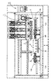
- FIG. 1 It is a front view which shows the whole polishing apparatus of this invention. An example which employ
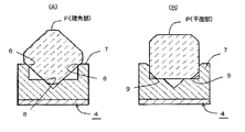
- FIG. 5B is a cross-sectional view showing a state in which a workpiece to be polished whose R surface is an R surface is placed on the base of the present invention, and FIG. (B) shows the case where the processed surface is a plane portion.
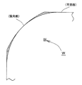
- FIG. 5 (B) is an enlarged view of a joining portion between the corner portion and the flat portion of the workpiece to be polished whose R-face is an R surface.
- FIG. 1 shows a polishing unit 1 stopped at a position before starting polishing at the right end in the drawing, and a workpiece W to be polished shown by a two-dot chain line placed on a base 4 in the right and left in the drawing.
- the gripping portion 6A at the tip end of the reference-side clamp shaft 12A that slides by driving the cylinder and the gripping portion 6B at the tip end of the driven-side clamp shaft 12B are retracted so that the workpiece W is not pinched.
- FIG. 1 is a front view of a polishing apparatus showing a state, and the polishing unit 1 is selectively set with three types of abrasive grain sizes as “rough polishing”, “medium polishing”, and “finish polishing”.
- Each polishing means 2 composed of a polishing brush is provided continuously from the right side to the left side in the drawing, and on the right side in the drawing of the “rough polishing” polishing means 2, the height of the processing surface P of the workpiece W before polishing is started.
- Height position detecting means 3 for detecting the position is provided.
- “Rough polishing” in the above-described triple polishing means 2 is provided for the purpose of scraping most of microcracks existing in the surface layer portion with a large polishing ability, and “medium polishing” was cut with a band saw or a wire saw. It is provided for the purpose of removing irregularities on the surface that is sometimes generated and refining the roughened surface by the “rough polishing”, and “for final polishing” is provided for the purpose of final adjustment of the surface roughness. Note that the polishing means 2 may be doubled if the removal of the surface irregularities and the adjustment of the surface roughness are completed at the stage of “medium polishing”.
- the “workpiece W to be polished W” of the polishing tool 10 is determined. ”The same rotation speed even if the polishing part (later angle part or flat part) is different”, “The polishing transfer speed where the polishing part differs depending on the difference in the horn part or flat part”, “Standard of finished polishing process product”
- Each control condition of the reference height at the start of polishing measured by the height position detecting means 3 and the “cutting amount with respect to the processed surface P of the workpiece W” is set in the control means 13.
- the operator can make sure that the processing surface P of one of the four corners of the workpiece W is horizontally upward on the base 4 between the gripping portions 6A and 6B of the clamping means 5.
- the “set switch for polishing portion (long angle or flat portion)” and “polishing start switch” are set to “ON”
- the polishing unit 1 moves to the left end in the figure, and the clamp
- the clamp shaft 12A on the reference side slides and the gripping portion 6A advances to the “reference end face position” in the drawing to position one end face of the workpiece W to be polished.
- the clamp shaft 12B on the driven side slides and the gripping portion 6B moves forward to come into contact with and press the other end surface of the workpiece W to be clamped and fixed.
- the polishing unit 1 is moved to the right side in the figure, and the height position detecting means 3 is activated to detect the height of the processed surface P of the work W to be polished, and the signal is transmitted to the control means 13 to perform arithmetic processing. Then, after the cutting amount of the tip of the polishing tool 10 of the polishing means 2 with respect to the processing surface P of the workpiece W is automatically set, the “setting switch for the polishing processing portion (the corner portion or the flat portion)” Thus, the polishing unit 1 whose transfer speed is automatically set is further transferred to the right side in the drawing, and each polishing means 2 performs polishing in the order of “rough polishing”, “medium polishing”, and “finish polishing”.
- the clamp shafts 12A and 12B of the clamp means 5 holding the both end faces of the workpiece W are moved backward so that the gripping portions 6A and 6B at the tips of the clamp means 5 hold the workpiece W. Since the state is automatically released, the operator manually inverts the workpiece W placed on the base 4 so that the next processing surface P faces upward, and then the clamp shaft 12A of the clamp means 5 is used.
- the semi-automatic type polishing apparatus according to the first aspect of the present invention is configured such that 12B is moved forward again and both end surfaces of the workpiece W are sandwiched and fixed by the gripping portions 6A and 6B and the next processing surface P is automatically polished.
- the base 4 is lowered by an elevator means (not shown) to release the mounting and fixing state of the workpiece W.
- the workpiece W to be polished is
- the processing surface P to be polished next is rotated horizontally at a predetermined angle around the clamp shafts 12A and 12B by the rolling means 14A and 14B, and the workpiece 4 to be polished is set horizontally upward. W is again placed and fixed, and the processing surface P of each corner portion and each plane portion is sequentially polished for each surface, or the polishing processing of each corner portion is performed by the rotating means 14A, 14B.
- There is a fully automatic type of the second invention in which the processing surface P of each flat surface portion is automatically polished for each surface after being continuously rotated and simultaneously polished.
- FIG. 2 (A) and 2 (B) show an example of a polishing brush employed in the polishing tool 10 of the polishing means 2, and bundling hair materials made of synthetic resin such as nylon mixed with abrasive grains.
- the base of the polishing tool 10 is connected to a rotation drive source and is detachably attached to the rotating disk 11 so that the lower end is in contact with the processing surface P of the workpiece W to be polished.
- the polishing tool 10 can be removed from the rotating disk 11 and replaced with a new polishing tool 10.
- the polishing brush employed in the polishing tool 10 of the polishing means 2 is not limited to that shown in FIG. 2, and the polishing tool 10 made of a hair material mixed with abrasive grains (not shown) is directly attached to the rotating disk 11 and fixed. If the polishing tool 10 is worn, the rotating disk 11 may be replaced together.
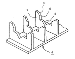
- FIG. 3 is a partially cutaway perspective view showing the base 4 that can be placed horizontally upward with either one of the horn portion or the flat portion of the workpiece W as a processing surface P.
- FIG. 4 is an explanatory view showing the manufacturing process of the flat plate-shaped receiving member 7 standing on the base 4, and the receiving member 7 has any one corner portion of the workpiece W to be polished.
- a notch (V) 8 is formed on which the lower flat portion is placed so that the one corner portion can be placed horizontally upward when polishing, and each of the workpieces W to be polished is formed.
- the notch (L) 9 is a notch (V) that can lock the lower corner portion so that the one planar portion can be placed upward when any one of the planar portions is polished. 8 is formed.
- the base 4 shown in the said FIG. 3 showed the die
- FIGS. 5A and 5B are perspective views showing an example in which the shape of the workpiece W is a quadrangular prism
- FIG. 5A is a perspective view of a square surface cut out from a rectangular raw material.
- the part is square and has a fine C surface
- (B) is a four-sided part cut out from a cylindrical raw material, leaving a cylindrical part of the raw material at the corner. It is formed so as to be an R plane.
- 6A and 6B are cross-sectional views of the workpiece (W) viewed from the side where the workpiece (W) is placed on the base 4, and (A) is a corner portion of the workpiece W to be polished. Shows a state in which the workpiece W is placed on the receiving member 7 of the base 4 with the processing surface P facing upward, and (B) shows the polishing of the flat portion of the workpiece W 3 shows a state where the workpiece W is placed on the receiving member 7 of the base 4 with the processing surface P facing upward when processing.
- the workpiece W is a quadrangular columnar silicon block, and the four planar portions and the four corners of the workpiece W are polished using the polishing apparatus of the present invention and exist in the surface layer portion. Micro-cracks and surface irregularities are removed to reduce the surface roughness and evaluate the polishing effect.
- a silicon wafer is formed by slicing the silicon block with a wire saw, the silicon wafer is cracked or chipped. An example in which the incidence of defective products due to the above can be reduced will be described.
- a single-crystal silicon ingot having a cylindrical cross section is cut to a length (L) of 500 mm using a band saw or wire saw.
- the cylindrical wall surface is cut and removed in the length direction to form four plane portions, and the arcuate corner where the two plane portions intersect is left with a circular arc width of a part of the cylindrical wall surface before cutting leaving about 25 mm.
- the rectangular prism shape shown in FIG. 5 (B) is used, and the size is ( ⁇ ) 125 mm ⁇ 125 mm and (L) 500 mm.
- Microcracks having a depth of 80 to 100 ⁇ m are present in the surface corner portion and the surface portion of the planar portion of the workpiece W before polishing, and the surface roughness is (Ry) 9 to 11 ⁇ m,
- the incidence of defective products due to cracks, chips, etc. was 5-6%.
- the silicon block as the workpiece (W) was polished by using the polishing apparatus according to the first invention to remove microcracks and irregularities and the surface roughness.
- the result of reducing the occurrence rate of defective products due to cracks, chips, etc. when the silicon block is formed by slicing the silicon block after miniaturization will be described.
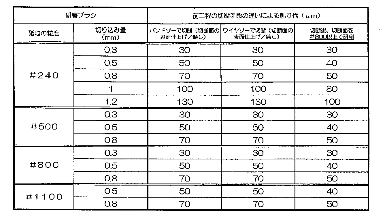
- a silicon ingot is cut with respect to the cutting amount for each abrasive grain size of the polishing brush” created to set the cutting amount by which the tip of the polishing tool 10 of the polishing means 2 protrudes from the processing surface P of the workpiece W.
- Table 2 below shows the reference materials showing the relationship between the difference in the cutting means in the previous step of forming the silicon block and the machining allowance ( ⁇ m) of the workpiece W depending on whether or not the surface of the cut surface is finished.
- any one of the corners of the workpiece (W) is horizontally upward on the base 4 between the gripping portions 6A and 6B of the clamp means 5. Then, the polishing start switch of the control means 13 is turned “ON” to start the polishing process, and the gripping portions 6A and 6B are made to be polished as the clamp shafts 12A and 12B of the clamp means 5 move forward and backward.
- the polishing time required for polishing one silicon block including the set time of the workpiece W is 24 minutes 34 seconds to 24 minutes 45 seconds (average: 24 minutes 40 seconds).
- the occurrence rate was reduced by 1.0%. .
- the location where the maximum depth (1.6 ⁇ m) of the microcracks is present is the “joint location between the corner portion and the plane portion” shown in FIG. 7, and is present in another corner portion or the plane portion.
- the depth of the micro cracks was 0.7 to 1.0 ⁇ m. Therefore, in the means for polishing the processing surface (P) of each corner and each plane portion on a surface-by-surface basis, the “joint portion between the corner portion and the plane portion” as shown by the hatched portion in FIG. Judge that polishing is difficult.
- microcracks when the maximum depth of microcracks is in the range of 2.3 ⁇ m, there is little effect on the incidence of defective products due to cracks or chips when sliced into a silicon wafer with a thickness of several tens of microns. Also turned out. Conventionally, it is considered that when the depth of microcracks is “3.0 ⁇ m or more”, the occurrence rate of the defective product is increased.
- the same silicon block as that of the first embodiment is used for the workpiece W and the polishing apparatus according to the second invention is used for the polishing apparatus, and the rotating means 14A and 14B are continuously rotated to clamp the workpiece W to be polished.
- the rotating means 14A and 14B are rotated by a predetermined angle (“90 degrees” in this embodiment) to obtain 4 Defective product due to the progress of polishing the flat surface for each surface, the remaining state and surface roughness of microcracks in the silicon block, and cracks / chips when the silicon block is sliced into a silicon wafer The result of reducing the occurrence rate is described.
- either one of the corner portion or the flat portion of the workpiece (W) is horizontally upward on the base 4 between the gripping portions 6A and 6B of the clamp means 5.
- the polishing start switch of the control means 13 is turned “ON” and the polishing process is started, the clamp shafts 12A and 12B of the clamp means 5 advance and the gripping portions 6A and 6B are polished.
- the rotating means 14A and 14B rotate the workpiece W continuously at a speed of 105 min-1 to simultaneously polish the four corners. Processing is performed.
- the rotating means 14A and 14B rotate the workpiece (W) by 90 degrees to set the surface to face upward for each plane portion, and sequentially polish the workpiece. In the same manner as in Example 1, three silicon blocks were polished.
- the occurrence rate was reduced by 1.8%.
- the bristle material made of synthetic resin such as nylon containing abrasive grains may be planted at the bottom of the polishing means 2 without using the polishing tool 10.
- the bristle material may be planted in a ring shape, that is, along the outer periphery of the bottom of the polishing means 2 or substantially parallel.
- a fibrous elastic body made of a synthetic resin containing abrasive grains may be entangled with each other and implanted at the bottom of the polishing means.
- the type of the synthetic resin and the content of the abrasive grains are appropriately selected so that the elastic bodies are entangled with each other, and the elasticity is such that it does not break when it comes into contact with the workpiece.
- polishing means may be substantially the same.
- a plurality of polishing means 2 may be installed so that different surfaces such as an upper surface and a corner portion adjacent to the upper surface can be processed simultaneously. Also in this case, a plurality of polishing means 2 may be connected to the polishing means 2 installed for processing each surface.
- the present embodiment has been described in accordance with the grinding method of the silicon block.
- the present invention is not limited to the silicon block, and can be suitably used for all hard and brittle materials such as ceramics.
- Polishing unit 2 DESCRIPTION OF SYMBOLS 1 Polishing unit 2 Polishing means 3 Height position detection means 4 Base 5 Clamping means 6A Grasping part (reference position side) 6B Grip part (driven side) 7 Receiving member 8 Notch V 9 Notch L 10 Polishing tool 11 Turntable 12A Clamp shaft (reference position side) 12B Clamp shaft (driven side) 13 Control means 14A Rotation means (reference position side) 14B Rotating means (driven side) W Workpiece P Work surface
Landscapes
- Engineering & Computer Science (AREA)
- Mechanical Engineering (AREA)
- Chemical & Material Sciences (AREA)
- Ceramic Engineering (AREA)
- Inorganic Chemistry (AREA)
- Finish Polishing, Edge Sharpening, And Grinding By Specific Grinding Devices (AREA)
- Grinding And Polishing Of Tertiary Curved Surfaces And Surfaces With Complex Shapes (AREA)
- Constituent Portions Of Griding Lathes, Driving, Sensing And Control (AREA)
- Polishing Bodies And Polishing Tools (AREA)
- Mechanical Treatment Of Semiconductor (AREA)
Abstract
Description
特許文献2: 特許第3405411号公報
前記、第1の発明によれば、a)研磨開始前に「研磨加工完成品の標準片(マスターワーク)」を基台(4)上に載置して研磨手段2の研磨具10(研磨ブラシ)の先端の研磨加工を開始する高さ位置を設定したのち、b)前記基台(4)の研磨加工完成品の標準片を取り外し、被研磨加工物(W)をその加工面(P)が上向きとなるように載置し、c)「研磨手段(2)の砥材の粒度」、「被研磨加工物(W)の前工程における切断条件」、「被研磨加工物(W)の研磨加工部位(平面部または陵角部)」の研磨加工条件を制御手段(13)に入力した後、研磨開始すれば、クランプ手段(5)の把持部(6A)、(6B)が被研磨加工物(W)の両端面を挟持して基台(4)上に固定し、例えば、被研磨加工物(W)の前工程における切断後の外形寸法に誤差が生じてバラツキがあった場合であっても、研磨手段(2)の研磨具(10)先端の「被研磨加工物(W)の加工面(P)に対する切り込み量」が前記高さ位置検出手段(3)の高さ位置検出信号によって演算処理され研磨加工前に自動設定されて最良の研磨加工ができる。その研磨加工が終了したら、該被研磨加工物(W)の両端面を挟持している前記クランプ手段(5)の把持部(6A)、(6B)が自動解除されるから、基台(4)に載置されている被研磨加工物(W)を次の加工面(P)が上向きになるように作業者が手動により反転したのち、クランプ手段(5)の把持部(6A)、(6B)を作動させて被研磨加工物(W)の両端面を挟持固定して次の加工面(P)の研磨加工を行うことができる。
前記した一連の研磨工程における被研磨加工物(W)の加工面(P)の設定は、作業者の手動によるものであるが、研磨手段(2)の研磨具(10)の先端の被研磨加工物(W)への切込み量や、被研磨加工物(W)の加工面(P)に所定の回転速度で接触回転して研磨加工する作動は自動制御によるものであるから、最良の研磨加工ができ生産性の向上を図ることができる。
前記した一連の研磨加工を、作業者の手作業を必要とせず、全自動で被研磨加工物(W)の各陵角部と各平面部の研磨加工を1加工面(P)毎に順次行うことができるものである。

a)〔研磨手段2の研磨粗さの選択設定〕研磨ブラシの砥粒の粒度を、上記表1を参考にして粗研磨用:#240、中研磨用:#500、仕上げ研磨用:#800、の3種類を選定して連設した研磨手段2とする。
b)〔研磨手段2の各研磨具10の基準高さの設定〕研磨加工完成品の標準片(マスターワーク)を基台4に載置して、該標準片の陵角部および平面部の高さ位置を高さ位置検出手段3により測定することにより、その測定結果が研磨手段2の各研磨具10の研磨開始前の基準高さとして制御手段13に自動設定される。
c)〔研磨手段2の研磨具10の回転速度の設定〕15m/sec。
d)〔研磨手段2の研磨具10の研磨移送速度の設定〕(陵角部の固定研磨)40mm/sec、(平面部の研磨)20mm/sec。
e)〔研磨手段2の各研磨具10の加工面Pに対する切り込み量の設定〕前記選択設定された各研磨ブラシの加工面(P)に対する切り込み量を、上記表2を参考にして粗研磨用(#240):0.5mm、中研磨用(#500):0.7mm、仕上げ研磨用(#1100):0.8mm、に決定する。
研磨具10を使用せず、砥粒を含有したナイロン等の合成樹脂から成る毛材を、研磨手段2の底部に植設してもよい。前記毛材の植設はリング状、即ち研磨手段2底部の外周に沿うように、または略平行となるように行ってもよい。
2 研磨手段
3 高さ位置検出手段
4 基台
5 クランプ手段
6A 把持部(基準位置側)
6B 把持部(従動側)
7 受け部材
8 切欠きV
9 切欠きL
10 研磨具
11 回転盤
12A クランプ軸(基準位置側)
12B クランプ軸(従動側)
13 制御手段
14A 回転手段(基準位置側)
14B 回転手段(従動側)
W 被研磨加工物
P 加工面
Claims (17)
- 被研磨加工物の形状が多角柱状の各平面部および各陵角部を研磨する研磨装置であって、該被研磨加工物(W)の各平面部のうち1平面部または各陵角部のうち1陵角部のいずれかを研磨する加工面として水平上向きとなるように載置できるようにした基台と、前記被研磨加工物を研磨加工する時にその両端面を挟持し、研磨終了後に前記挟持状態を解除する把持部を先端に取付けて前後動するようにしたクランプ軸からなるクランプ手段と、前記被研磨加工物を研磨加工する時に、前記加工面に研磨具の先端が接触回転しながら研磨加工する研磨手段を移送する研磨ユニットと、前記被研磨加工物の加工面の高さ位置を研磨加工前に検出し該高さ位置検出信号を制御手段に記憶させる高さ位置検出手段と、を備え、前記制御手段が前記高さ位置検出信号により研磨手段の研磨具の先端の切込み量を演算処理して研磨加工を行うようにしたことを特徴とする多角柱状部材の研磨装置。
- 前記把持部に両端面が挟持された被研磨加工物を前記クランプ軸の軸心を中心に所定の回転角度が設定されて被研磨加工物の加工面が上向きとなるように回転するタクト回転、または回転速度が設定されて回転する連続回転のどちらかに選択して回転するようにした回転手段と、前記基台を昇降させる昇降手段と、を備え、研磨加工前に研磨加工する被研磨加工物の多角柱形状の角数と、該被研磨加工物の前記陵角部の研磨加工条件である前記回転手段によるタクト回転、または連続回転のどちらかを選択して前記制御手段に設定するようにしたことを特徴とする請求項1記載の多角柱状部材の研磨装置。
- 前記研磨手段が、砥粒を含有した毛材であり、該毛材が該研磨手段の底部にリング状に複数本植設されている研磨ブラシであることを特徴とする請求項1または請求項2記載の多角柱状部材の研磨装置。
- 前記研磨手段が、砥粒を含有した毛材を複数本束ねた研磨具の基部が回転板に複数本植設されている研磨ブラシであることを特徴とする請求項1または請求項2記載の多角柱状部材の研磨装置。
- 前記研磨手段が、砥粒を含有し互いが絡み合った繊維状の弾性体が該研磨手段の底部に複数本植設されている研磨ブラシであることを特徴とする請求項1または請求項2記載の多角柱状部材の研磨装置。
- 前記研磨手段を複数台水平に連接したことを特徴とする請求項3乃至請求項5のいずれか記載の多角柱状部材の研磨装置。
- 前記研磨手段を、前記多角柱状部材の少なくとも2以上の異なる面に配置したことを特徴とする請求項3乃至請求項5のいずれか記載の多角柱状部材の研磨装置。
- 前記研磨手段を前記多角柱状部材の少なくとも2以上の異なる面に、それぞれ複数台水平に配置したことを特徴とする請求項3乃至請求項5のいずれか記載の多角柱状部材の研磨装置。
- 前記毛材に混合される砥粒の粒度がF180~#2000(JIS R6001:1998)であって、その粒度が異なる研磨手段を2種類以上選択し、該研磨手段を、その粒度が「粗」から「細」の順に研磨加工するように連設したことを特徴とする請求項6または請求項8記載の多角柱状部材の研磨装置。
- 前記毛材に混合される砥粒の粒度がF180~#2000であって、その粒度が略同一の研磨手段を選択し、該研磨手段を連接したことを特徴とする請求項6または請求項8記載の多角柱状部材の研磨装置。
- 前記基台に被研磨加工物を載置する受け部材に、前記被研磨加工物のいずれか1陵角部を研磨するときに、該1陵角部を水平上向きに載置できるようにその下側となる平面部が接する切欠きVと、該切欠きVに、前記被研磨加工物の各平面部のいずれか1平面部を研磨するときに、該1平面部を上向きに載置できるようにその下側となる陵角部が係止できる切欠きLと、を形成したことを特徴とする請求項1乃至請求項10のいずれか記載の多角柱状部材の研磨装置。
- 前記請求項1乃至11のいずれか記載の多角柱状部材の研磨装置により、被加工物の表層より100μm以下に存在するマイクロクラックが除去され、かつ研磨加工面の表面粗さRy(JIS B0601:1994)が3μm以下とされたことを特徴とする多角柱状部材。
- 前記多角柱部材はシリコンブロックまたはセラミックスであることを特徴とする請求項12記載の多角柱状部材。
- 前記請求項1に記載の多角柱状部材の研磨装置において、基台に載置されている被研磨加工物の複数ある加工面のうち各加工面の研磨が終了した時点で前記クランプ手段のクランプ軸が後退して把持部の挟持状態が解除された前記被研磨加工物の次の加工面を水平上向きとなるように作業者が手動で反転したのち、前記クランプ手段のクランプ軸が前進して一方の把持部が被研磨加工物の基準端面位置に到達して停止し他方のクランプ軸がさらに前進してその把持部が被研磨加工物の他方の端面を押圧して挟持し前記に設定された次の加工面を研磨加工するようにし、すべての加工面を研磨加工する手順を、各陵角部の研磨を終了させた後に各平面部の研磨加工を行うようにしたことを特徴とする多角柱状部材の研磨方法。
- 前記請求項2に記載の多角柱状部材の研磨装置において、基台に載置されている被研磨加工物の両端面をクランプ手段の把持部により挟持した状態で前記基台を下降させて被研磨加工物より離間させておき、被研磨加工物の各陵角部の研磨を、所定の回転角度が設定された前記回転手段を回転させて1陵角部毎に研磨面が上向きとなるように位置決めして研磨するようにしたタクト研磨、または回転速度が設定された前記回転手段を連続回転させて各陵角部を同時に研磨するようにした連続研磨のどちらかの方法によりすべての陵角部の研磨加工を終了させたのち、所定の回転角度が設定された前記回転手段を回転させて1平面部毎に研磨加工してすべての平面部の研磨加工を行うようにしたことを特徴とする多角柱状部材の研磨方法。
- 前記請求項6または請求項8に記載の多角柱状部材の研磨装置において、前記毛材に混合される砥粒の粒度がF180~#2000であって、その粒度が異なる研磨手段を2種類以上選択し、該研磨手段をその粒度が「粗」から「細」の順に研磨加工するように連設して研磨することを特徴とする多角柱状部材の研磨方法。
- 前記請求項6または請求項8に記載の多角柱状部材の研磨装置において、前記毛材に混合される砥粒の粒度がF180~#2000であって、その粒度が略同一の研磨手段を選択し、該研磨手段を連接して研磨することを特徴とする多角柱状部材の研磨方法。
Priority Applications (3)
| Application Number | Priority Date | Filing Date | Title |
|---|---|---|---|
| KR1020127011097A KR101267439B1 (ko) | 2009-10-30 | 2010-07-12 | 다각기둥형상 부재의 연마 장치 및 그 연마 방법 |
| CN201080001511.5A CN102164710B (zh) | 2009-10-30 | 2010-07-12 | 多棱柱状部件的研磨装置及其研磨方法 |
| JP2010546168A JP4816815B2 (ja) | 2009-10-30 | 2010-07-12 | 多角柱状部材の研磨装置およびその研磨方法 |
Applications Claiming Priority (4)
| Application Number | Priority Date | Filing Date | Title |
|---|---|---|---|
| JP2009249591 | 2009-10-30 | ||
| JP2009-249591 | 2009-12-25 | ||
| JP2010133328 | 2010-06-10 | ||
| JP2010-133328 | 2010-06-10 |
Publications (1)
| Publication Number | Publication Date |
|---|---|
| WO2011052267A1 true WO2011052267A1 (ja) | 2011-05-05 |
Family
ID=43921698
Family Applications (1)
| Application Number | Title | Priority Date | Filing Date |
|---|---|---|---|
| PCT/JP2010/061756 Ceased WO2011052267A1 (ja) | 2009-10-30 | 2010-07-12 | 多角柱状部材の研磨装置およびその研磨方法 |
Country Status (5)
| Country | Link |
|---|---|
| JP (1) | JP4816815B2 (ja) |
| KR (1) | KR101267439B1 (ja) |
| CN (2) | CN102164710B (ja) |
| TW (1) | TWI389770B (ja) |
| WO (1) | WO2011052267A1 (ja) |
Cited By (3)
| Publication number | Priority date | Publication date | Assignee | Title |
|---|---|---|---|---|
| CN102862104A (zh) * | 2012-09-25 | 2013-01-09 | 济南济变志亨电力设备有限公司 | 一种线圈浇口打磨装置 |
| CN109822458A (zh) * | 2019-04-10 | 2019-05-31 | 东莞市金太阳精密技术有限责任公司 | 一种抛磨机的物料承载移动机构 |
| CN113276001A (zh) * | 2021-06-16 | 2021-08-20 | 王一帆 | 一种新材料用多工位抛光机 |
Families Citing this family (18)
| Publication number | Priority date | Publication date | Assignee | Title |
|---|---|---|---|---|
| JP2014147978A (ja) * | 2011-05-31 | 2014-08-21 | Sintokogio Ltd | 柱状部材の加工装置 |
| TW201249600A (en) * | 2011-06-08 | 2012-12-16 | Thintech Materials Technology Co Ltd | Processing method for silicon target surface |
| TWI564948B (zh) * | 2011-09-15 | 2017-01-01 | 新東工業股份有限公司 | Hard and brittle materials for grinding, grinding processing systems and grinding, grinding methods |
| CN103084946B (zh) * | 2011-10-31 | 2015-07-15 | 鸿准精密模具(昆山)有限公司 | 去毛刺机 |
| JP5843155B2 (ja) * | 2012-01-11 | 2016-01-13 | 新東工業株式会社 | 研磨ブラシ |
| CN103286655A (zh) * | 2013-06-18 | 2013-09-11 | 南通综艺新材料有限公司 | 一种多晶硅c角毛刷抛光机 |
| DE112014004192T5 (de) | 2013-09-13 | 2016-05-25 | Taimei Chemicals Co., Ltd | Polierverfahren, bürstenförmiger Schleifstein, Polierbürste und Drahtbündelung |
| KR101572103B1 (ko) * | 2014-09-11 | 2015-12-04 | 주식회사 엘지실트론 | 웨이퍼 연마 장치 |
| CN104608020B (zh) * | 2015-02-03 | 2017-01-18 | 中国电子科技集团公司第四十六研究所 | 一种双包层光纤八角形内包层的加工方法及夹具 |
| CN106078470B (zh) * | 2016-08-04 | 2018-07-10 | 乐清市通达有线电厂 | 轴承抛光检测一体装置 |
| CN108214175A (zh) * | 2016-12-12 | 2018-06-29 | 广东科达洁能股份有限公司 | 一种高精度自动推砖装置 |
| CN106625104B (zh) * | 2017-03-22 | 2018-11-30 | 天津盛世舜合自动化技术有限公司 | 一种马桶底部加工装置 |
| CN108655868B (zh) * | 2018-07-02 | 2023-09-05 | 中信戴卡股份有限公司 | 一种铝合金车轮刷毛刺设备 |
| CN110370094B (zh) * | 2019-07-29 | 2020-11-10 | 丹阳丹耀光学有限公司 | 一种磨砂棱镜的加工工艺及设备 |
| CN111286778B (zh) * | 2020-03-31 | 2025-08-15 | 山东吉威医疗制品有限公司 | 一种金属支架自动抛光设备 |
| CN112518583A (zh) * | 2020-11-23 | 2021-03-19 | 德清博发智能科技有限公司 | 一种用于机械的工件加工装置 |
| CN115070538B (zh) * | 2022-07-18 | 2023-12-01 | 广西强强碳素股份有限公司 | 一种全方位自动除尘装置 |
| CN116276127B (zh) * | 2023-05-23 | 2023-08-08 | 浙江大铭汽车零部件有限公司 | 一种可消除外圈三角棱圆的车加工装置及加工工艺 |
Citations (12)
| Publication number | Priority date | Publication date | Assignee | Title |
|---|---|---|---|---|
| JPS55160765U (ja) * | 1979-05-04 | 1980-11-18 | ||
| EP0150045A2 (de) * | 1984-01-21 | 1985-07-31 | Black & Decker Overseas AG | Führungsanschlag |
| JPS63176070U (ja) * | 1987-05-07 | 1988-11-15 | ||
| JPS6416266U (ja) * | 1987-07-16 | 1989-01-26 | ||
| EP0319032A2 (de) * | 1987-12-04 | 1989-06-07 | Hundegger, Hans | Zimmerei-Abbundanlage |
| JPH09290343A (ja) * | 1996-04-26 | 1997-11-11 | Toshiba Corp | 横転装置 |
| JP2003231048A (ja) * | 2002-02-08 | 2003-08-19 | Okuma Corp | ワークの研削方法 |
| JP2007111781A (ja) * | 2005-10-18 | 2007-05-10 | Gifu Tada Seiki:Kk | 被加工物加工保持装置及び被加工物加工装置及びその加工方法 |
| JP2007130723A (ja) * | 2005-11-10 | 2007-05-31 | Asahi Techno Glass Corp | ガラス基板の角部面取り用保持装置及びガラス基板の角部面取り方法 |
| JP2009136954A (ja) * | 2007-12-05 | 2009-06-25 | Makino J Kk | ワーク加工方法及び数値制御工作機械並びにワーク取付具 |
| WO2009084101A1 (ja) * | 2007-12-28 | 2009-07-09 | Sintobrator, Ltd. | 角柱状部材の研磨装置 |
| JP2009233795A (ja) * | 2008-03-27 | 2009-10-15 | Jcm:Kk | シリコンインゴット用測定装置 |
Family Cites Families (7)
| Publication number | Priority date | Publication date | Assignee | Title |
|---|---|---|---|---|
| JPS55160765A (en) * | 1979-05-29 | 1980-12-13 | Sankyo Co Ltd | Preparation of 4-benzoylpyrazole |
| JPS63176070A (ja) * | 1987-01-16 | 1988-07-20 | Matsushita Electric Ind Co Ltd | 映像信号クランプ装置 |
| JPS6416266A (en) * | 1987-07-10 | 1989-01-19 | Hitachi Ltd | Controller for current type converter |
| JP3936448B2 (ja) * | 1997-10-20 | 2007-06-27 | 株式会社シンク・ラボラトリー | 円筒体の鏡面研磨方法 |
| JP2001301953A (ja) * | 2000-04-17 | 2001-10-31 | Sumitomo Kinzoku Kozan Siporex Kk | 被加工物の転向搬送装置 |
| AU2003281502A1 (en) * | 2002-07-22 | 2004-02-09 | Taimei Chemicals Co., Ltd. | Method of producing brush-like grind stone, the brush-like grind stone, and brush for grind machine |
| DE102006007055B4 (de) * | 2006-02-15 | 2008-07-17 | Bsh Holice A.S. | Verfahren zum Schleifen von stabförmigen Werkstücken, Schleifmaschine zur Durchführung des Verfahrens und Schleifzelle in Zwillingsanordnung |
-
2010
- 2010-07-12 KR KR1020127011097A patent/KR101267439B1/ko active Active
- 2010-07-12 JP JP2010546168A patent/JP4816815B2/ja active Active
- 2010-07-12 WO PCT/JP2010/061756 patent/WO2011052267A1/ja not_active Ceased
- 2010-07-12 CN CN201080001511.5A patent/CN102164710B/zh active Active
- 2010-07-20 TW TW099123737A patent/TWI389770B/zh active
- 2010-09-02 CN CN201010273884XA patent/CN102069446A/zh active Pending
Patent Citations (12)
| Publication number | Priority date | Publication date | Assignee | Title |
|---|---|---|---|---|
| JPS55160765U (ja) * | 1979-05-04 | 1980-11-18 | ||
| EP0150045A2 (de) * | 1984-01-21 | 1985-07-31 | Black & Decker Overseas AG | Führungsanschlag |
| JPS63176070U (ja) * | 1987-05-07 | 1988-11-15 | ||
| JPS6416266U (ja) * | 1987-07-16 | 1989-01-26 | ||
| EP0319032A2 (de) * | 1987-12-04 | 1989-06-07 | Hundegger, Hans | Zimmerei-Abbundanlage |
| JPH09290343A (ja) * | 1996-04-26 | 1997-11-11 | Toshiba Corp | 横転装置 |
| JP2003231048A (ja) * | 2002-02-08 | 2003-08-19 | Okuma Corp | ワークの研削方法 |
| JP2007111781A (ja) * | 2005-10-18 | 2007-05-10 | Gifu Tada Seiki:Kk | 被加工物加工保持装置及び被加工物加工装置及びその加工方法 |
| JP2007130723A (ja) * | 2005-11-10 | 2007-05-31 | Asahi Techno Glass Corp | ガラス基板の角部面取り用保持装置及びガラス基板の角部面取り方法 |
| JP2009136954A (ja) * | 2007-12-05 | 2009-06-25 | Makino J Kk | ワーク加工方法及び数値制御工作機械並びにワーク取付具 |
| WO2009084101A1 (ja) * | 2007-12-28 | 2009-07-09 | Sintobrator, Ltd. | 角柱状部材の研磨装置 |
| JP2009233795A (ja) * | 2008-03-27 | 2009-10-15 | Jcm:Kk | シリコンインゴット用測定装置 |
Cited By (5)
| Publication number | Priority date | Publication date | Assignee | Title |
|---|---|---|---|---|
| CN102862104A (zh) * | 2012-09-25 | 2013-01-09 | 济南济变志亨电力设备有限公司 | 一种线圈浇口打磨装置 |
| CN109822458A (zh) * | 2019-04-10 | 2019-05-31 | 东莞市金太阳精密技术有限责任公司 | 一种抛磨机的物料承载移动机构 |
| CN109822458B (zh) * | 2019-04-10 | 2024-03-26 | 东莞市金太阳精密技术有限责任公司 | 一种抛磨机的物料承载移动机构 |
| CN113276001A (zh) * | 2021-06-16 | 2021-08-20 | 王一帆 | 一种新材料用多工位抛光机 |
| CN113276001B (zh) * | 2021-06-16 | 2022-12-16 | 江苏宁博机械制造有限公司 | 一种新材料用多工位抛光机 |
Also Published As
| Publication number | Publication date |
|---|---|
| TW201114549A (en) | 2011-05-01 |
| CN102164710B (zh) | 2014-08-20 |
| CN102069446A (zh) | 2011-05-25 |
| TWI389770B (zh) | 2013-03-21 |
| KR101267439B1 (ko) | 2013-05-31 |
| KR20120102046A (ko) | 2012-09-17 |
| JP4816815B2 (ja) | 2011-11-16 |
| CN102164710A (zh) | 2011-08-24 |
| JPWO2011052267A1 (ja) | 2013-03-14 |
Similar Documents
| Publication | Publication Date | Title |
|---|---|---|
| JP4816815B2 (ja) | 多角柱状部材の研磨装置およびその研磨方法 | |
| TWI535531B (zh) | Grinding / grinding processing equipment and grinding / grinding processing method for polygonal columnar members | |
| JP5842920B2 (ja) | 硬脆性材料の研削・研磨加工システム、および研削・研磨方法 | |
| CN101972982B (zh) | 圆柱状部件的研磨装置及其研磨方法 | |
| CN102652049B (zh) | 圆柱状部件的研磨装置、圆柱状部件以及圆柱状部件的研磨方法 | |
| TWI589398B (zh) | Columnar processing equipment | |
| JP2011136382A (ja) | シリコンインゴットの面取り加工装置 | |
| JP2016016485A (ja) | インゴットブロックの複合面取り加工装置および面取り加工方法 | |
| WO2019102629A1 (ja) | 多角柱状部材の加工装置および加工方法 | |
| TW201509594A (zh) | 半導體晶圓硏削裝置、半導體晶圓製造方法、及半導體晶圓硏削方法 | |
| JP2007250962A (ja) | ウエーハの製造方法 |
Legal Events
| Date | Code | Title | Description |
|---|---|---|---|
| WWE | Wipo information: entry into national phase |
Ref document number: 201080001511.5 Country of ref document: CN |
|
| WWE | Wipo information: entry into national phase |
Ref document number: 2010546168 Country of ref document: JP |
|
| 121 | Ep: the epo has been informed by wipo that ep was designated in this application |
Ref document number: 10826402 Country of ref document: EP Kind code of ref document: A1 |
|
| ENP | Entry into the national phase |
Ref document number: 20127011097 Country of ref document: KR Kind code of ref document: A |
|
| NENP | Non-entry into the national phase |
Ref country code: DE |
|
| WWE | Wipo information: entry into national phase |
Ref document number: 4417/CHENP/2012 Country of ref document: IN |
|
| 122 | Ep: pct application non-entry in european phase |
Ref document number: 10826402 Country of ref document: EP Kind code of ref document: A1 |