WO2011052151A1 - マスタシリンダ用作動液流動制御弁、これを備えるマスタシリンダ、このマスタシリンダを用いたブレーキ装置 - Google Patents
マスタシリンダ用作動液流動制御弁、これを備えるマスタシリンダ、このマスタシリンダを用いたブレーキ装置 Download PDFInfo
- Publication number
- WO2011052151A1 WO2011052151A1 PCT/JP2010/006138 JP2010006138W WO2011052151A1 WO 2011052151 A1 WO2011052151 A1 WO 2011052151A1 JP 2010006138 W JP2010006138 W JP 2010006138W WO 2011052151 A1 WO2011052151 A1 WO 2011052151A1
- Authority
- WO
- WIPO (PCT)
- Prior art keywords
- master cylinder
- hydraulic fluid
- hydraulic
- flow control
- valve body
- Prior art date
- Legal status (The legal status is an assumption and is not a legal conclusion. Google has not performed a legal analysis and makes no representation as to the accuracy of the status listed.)
- Ceased
Links
Images



Classifications
-
- B—PERFORMING OPERATIONS; TRANSPORTING
- B60—VEHICLES IN GENERAL
- B60T—VEHICLE BRAKE CONTROL SYSTEMS OR PARTS THEREOF; BRAKE CONTROL SYSTEMS OR PARTS THEREOF, IN GENERAL; ARRANGEMENT OF BRAKING ELEMENTS ON VEHICLES IN GENERAL; PORTABLE DEVICES FOR PREVENTING UNWANTED MOVEMENT OF VEHICLES; VEHICLE MODIFICATIONS TO FACILITATE COOLING OF BRAKES
- B60T11/00—Transmitting braking action from initiating means to ultimate brake actuator without power assistance or drive or where such assistance or drive is irrelevant
- B60T11/10—Transmitting braking action from initiating means to ultimate brake actuator without power assistance or drive or where such assistance or drive is irrelevant transmitting by fluid means, e.g. hydraulic
- B60T11/16—Master control, e.g. master cylinders
- B60T11/232—Recuperation valves
-
- Y—GENERAL TAGGING OF NEW TECHNOLOGICAL DEVELOPMENTS; GENERAL TAGGING OF CROSS-SECTIONAL TECHNOLOGIES SPANNING OVER SEVERAL SECTIONS OF THE IPC; TECHNICAL SUBJECTS COVERED BY FORMER USPC CROSS-REFERENCE ART COLLECTIONS [XRACs] AND DIGESTS
- Y10—TECHNICAL SUBJECTS COVERED BY FORMER USPC
- Y10T—TECHNICAL SUBJECTS COVERED BY FORMER US CLASSIFICATION
- Y10T137/00—Fluid handling
- Y10T137/7287—Liquid level responsive or maintaining systems
- Y10T137/7358—By float controlled valve
- Y10T137/7423—Rectilinearly traveling float
- Y10T137/7426—Float co-axial with valve or port
Definitions
- the present invention is used in a hydraulic operation device such as a hydraulic brake device using hydraulic pressure such as hydraulic pressure, and controls a flow of hydraulic fluid between a master cylinder and a reservoir tank for generating the hydraulic pressure.
- the present invention relates to a technical field of a cylinder hydraulic fluid flow control valve, a technical field of a master cylinder including the same, and a technical field of a brake device using the master cylinder.
- the electronic control unit operates the pump of the automatic brake device, and the hydraulic fluid in the reservoir tank is supplied to the brake cylinder by the operation of this pump. As a result, the hydraulic fluid in the brake cylinder is boosted and the automatic brake is activated.
- a hydraulic fluid flow control valve for a master cylinder is provided in a fluid passage between a reservoir tank and a master cylinder.
- This hydraulic fluid flow control valve for the master cylinder opens the fluid passage between the reservoir tank and the master cylinder when the hydraulic fluid is fed from the reservoir tank to the master cylinder, and operates from the reservoir tank to the master cylinder. Allow fluid flow.
- the master cylinder hydraulic fluid flow control valve communicates with the fluid passage between the reservoir tank and the master cylinder greatly narrowed when the automatic brake is released. Thus, when the automatic brake is released, the master cylinder hydraulic fluid flow control valve prevents residual pressure from being generated on the master cylinder side.
- the hydraulic fluid flow control valve a for the master cylinder described in Patent Document 1 is disposed in the hydraulic fluid supply hole c of the master cylinder b so as to be able to float up and down, and has a radial notch on the upper surface.
- a cylindrical valve seat member h having a seat g.
- the valve seat member h is formed of an elastic material such as grommet and seals between the master cylinder b and the reservoir tank f.
- the valve seat g of the valve seat member h interposed between the master cylinder b and the reservoir tank f is disposed outside the valve seat member h.
- the existing floating valve body e needs to be seated stably. Therefore, the diameter of the valve seat g (that is, the seating diameter of the floating valve body e on the valve seat g) is set to be relatively large.
- valve seat member h is formed of an elastic material, there is a possibility that the valve seat member h is deformed or damaged by an excessive force applied to the floating valve body e and the sealing performance of the valve seat member h is impaired. Conceivable. Furthermore, it is conceivable that the seating posture of the floating valve body e becomes unstable due to deformation or damage of the valve seat member h, and the hydraulic fluid flow control function of the master cylinder hydraulic fluid flow control valve a may be impaired. Furthermore, when the master cylinder b and the reservoir tank f are assembled, it is necessary to inspect the floating valve body e for missing parts or dropping off. For this reason, it can be considered that the number of work steps increases.
- the present invention has been made in view of such circumstances, and an object of the present invention is to effectively reduce the pressure receiving area of the floating valve body when seated on the valve seat and to maintain a good sealing function of the seal member. And it is providing the hydraulic fluid flow control valve for master cylinders which can suppress the increase in an assembly operation man-hour, the master cylinder provided with this, and the brake device using this master cylinder.
- a hydraulic fluid flow control valve for a master cylinder is disposed in a liquid passage between a reservoir tank and a master cylinder, and the floating valve body and the floating valve body are seated.
- a hydraulic fluid flow control valve for a master cylinder that has a valve seat capable of controlling the flow of hydraulic fluid between the reservoir tank and the master cylinder, and is liquid-tightly attached to the master cylinder with a seal member
- the floating valve body is accommodated in a cylindrical member forming the liquid passage so as to be movable up and down, and the valve seat is disposed in the cylindrical member.
- the upper end surface of the floating valve body is formed in a spherical shape, and the spherical upper end surface can be seated on the valve seat. It is said.
- a throttle passage that penetrates in the axial direction of the floating valve body and restricts the flow of the hydraulic fluid is disposed in the floating valve body, and the floating valve body When seated on the valve seat, the reservoir tank side from the valve seat and the master cylinder side from the valve seat communicate with each other only by the throttle passage.
- the hydraulic fluid flow control valve for a master cylinder according to the present invention is characterized in that the throttle passage is formed by a groove provided on an outer peripheral surface of the floating valve body.
- the floating member is provided with a stopper at the lower end of the cylindrical member.
- a master cylinder of the present invention includes a cylinder main body and a piston that is fluid-tightly and slidably inserted into the cylinder main body to form a hydraulic pressure chamber and that generates hydraulic pressure in the hydraulic pressure chamber during operation.
- a hydraulic fluid supply hole provided in the cylinder body and always communicating with the hydraulic pressure chamber, and a master cylinder hydraulic fluid flow control valve disposed in the hydraulic fluid supply hole, The cylinder hydraulic fluid flow control valve is the master cylinder hydraulic fluid flow control valve of the present invention.
- the brake device operates with a reservoir tank that stores hydraulic fluid, a master cylinder that is supplied with the hydraulic fluid in the reservoir tank and generates hydraulic pressure during operation, and hydraulic pressure from the master cylinder.
- a brake cylinder that generates a braking force of a normal brake by the operation of the master cylinder, and is disposed between the master cylinder and the brake cylinder and supplies the hydraulic fluid in the reservoir tank to the brake cylinder.
- the brake cylinder includes at least an automatic brake device that generates a braking force of an automatic brake
- the master cylinder is the master cylinder of the present invention.
- the floating valve body moves up and down in a cylindrical member that is liquid-tightly attached to the master cylinder with a seal member and forms a liquid passage.
- the valve seat is disposed in the tubular member while being accommodated. Thereby, a floating valve body does not contact
- the pressure receiving area of the seal member is small, the push-up force of the seal member due to the hydraulic pressure from the hydraulic chamber side of the master cylinder can be reduced. As a result, deformation or damage of the sealing member can be suppressed, and the sealing performance of the sealing member can be maintained well.
- the floating valve body and the valve seat are disposed in the cylindrical member, the pressure receiving area of the floating valve body can be reduced when the floating valve body is seated on the valve seat. Accordingly, the force applied to the floating valve body by the hydraulic pressure from the hydraulic pressure chamber when the automatic brake is released can reduce the force that pushes up the valve seat. Thereby, the seating attitude
- the floating valve body can be formed in a cylindrical shape that is long in the axial direction.
- the inclination of the floating valve body can be suppressed, and the seating posture of the floating valve body on the valve seat can be further stabilized.
- the upper end surface of the floating valve body which is the seating surface for the valve seat, is formed in a spherical shape, even if the floating valve body is slightly tilted, the seating posture of the floating valve body on the valve seat is more effective. Can be stabilized.
- a throttle passage that penetrates in the axial direction of the floating valve body and restricts the flow of hydraulic fluid is provided in the floating valve body, and when the floating valve body is seated on the valve seat, the reservoir tank side and the valve seat from the valve seat The master cylinder side is communicated with only the throttle passage. Therefore, even if the state where the floating valve body is seated on the valve seat is maintained, it is possible to finally prevent the residual pressure from being generated in the hydraulic pressure chamber of the master cylinder. Then, by appropriately setting the flow passage area of the throttle passage, various throttle amounts of the hydraulic fluid can be set.
- the throttle passage can be easily formed by forming the throttle passage with a groove provided on the outer peripheral surface of the floating valve body.
- the floating valve body is prevented from coming off at the lower end of the cylindrical member. Therefore, the floating valve body accommodated in the cylindrical member can be prevented from coming out of the cylindrical member. As a result, the floating valve body assembled in advance to the cylindrical member is prevented from coming off, so that it is possible to prevent the floating valve body from being missing or dropped when the cylindrical member is attached to the master cylinder. Therefore, it is not necessary to inspect the floating valve body one by one when the cylindrical member is attached to the master cylinder, and the work man-hour can be reduced correspondingly.
- the master cylinder hydraulic fluid flow control valve of the present invention is provided. Therefore, since the hydraulic fluid flow control function of the hydraulic fluid flow control valve for the master cylinder can be maintained satisfactorily, the hydraulic fluid is discharged and replenished during normal braking when the master cylinder is activated and during automatic braking when the master cylinder is not activated. can do. Therefore, each operation reliability of the normal brake and the automatic brake can be improved.
- the master cylinder of the present invention is provided. Therefore, as described above, the master cylinder can improve the operational reliability of the normal brake and the automatic brake, so that both the normal brake and the automatic brake can be operated reliably.
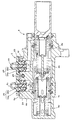
- FIG. 1 It is a figure showing typically a hydraulic brake device provided with an example of an embodiment of a hydraulic fluid flow control valve for master cylinders concerning the present invention. It is sectional drawing of a master cylinder provided with the working fluid flow control valve for master cylinders of this example.
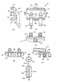
- the reservoir tank connector used for the master cylinder of this example is shown, (a) is a front view, (b) is a plan view, (c) is a left side view, and (d) is a IIID-IIID line in (b).
- (E) is a sectional view taken along line IIIE-IIIE in (b),
- (f) is a top view of the floating valve body, and
- (g) is a front view of the floating valve body.
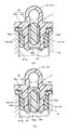
- the master cylinder hydraulic fluid flow control valve of this example is shown, (a) is a partial sectional view showing a seating state of the floating valve body on the valve seat, and (b) is a partial sectional view for explaining how the floating valve body is prevented from coming off. It is. It is sectional drawing which shows the other example of embodiment of the master cylinder which concerns on this invention. It is a fragmentary sectional view which shows the conventional hydraulic fluid flow control valve for master cylinders.
- FIG. 1 is a view schematically showing a brake device including an example of an embodiment of a reservoir tank connection connector according to the present invention.
- the hydraulic brake device 1 of this example is basically the same as a conventionally known two-system hydraulic brake device. That is, the hydraulic brake device 1 includes a brake pedal 2, a booster 3, a tandem master cylinder 4, a reservoir tank 5, a reservoir tank connection connector 6, two hydraulic fluid supply pipes, hoses 7, 8, and two systems. Brake cylinders and two hydraulic fluid pressure passages. Since the two brake fluid pressure systems on the brake cylinder side from the tandem master cylinder 4 have the same configuration, FIG. 1 shows only one brake fluid pressure system and this one brake fluid pressure system. The description and illustration of the other brake hydraulic system will be omitted.
- the tandem master cylinder 4 is a conventionally known tandem master cylinder.
- a primary piston 4a is slidably disposed in a cylinder hole of the cylinder body of the tandem master cylinder 4, and a primary hydraulic chamber 4b is defined by the primary piston 4a.
- a secondary piston 4c is slidably disposed in the cylinder hole of the cylinder body of the tandem master cylinder 4, and a secondary hydraulic chamber 4d is defined by the secondary piston 4c.
- the primary hydraulic chamber 4b is defined between the primary piston 4a and the secondary piston 4c.
- the reservoir tank 5 is disposed away from the tandem master cylinder 4 and the reservoir tank connector 6 is attached to the tandem master cylinder 4.
- the reservoir tank 5 and the reservoir tank connection connector 6 are connected to each other via the hoses 7 and 8.
- the hydraulic fluid in the reservoir tank 5 is supplied to the primary hydraulic chamber 4b and the secondary hydraulic chamber 4d of the tandem master cylinder 4 via the two systems of hoses 7, 8 and the reservoir tank connection connector 6, respectively.
- the primary hydraulic chamber 4b is connected to one of the two brake hydraulic systems, and the secondary hydraulic chamber 4d is connected to the other brake hydraulic system.
- the hydraulic fluid supplied to the primary hydraulic pressure chamber 4 b of the tandem master cylinder 4 is supplied to the brake cylinders 9 and 10 via the hydraulic pressure passage 11.
- the hydraulic pressure passage 11 is connected to the brake cylinders 9 and 10 by branch passages 11a and 11b branched in the middle.
- the hydraulic brake device 1 includes a hydraulic unit (H / U) 13.
- This H / U 30 performs automatic brake control such as brake pressure control and traction control (TRC) of an anti-lock brake system (ABS).
- TRC brake pressure control and traction control
- ABS anti-lock brake system
- a normally open on-off valve 31 disposed in the hydraulic pressure passage 11 a bypass passage 32 that bypasses the on-off valve 31, and a bypass passage 32 are arranged.
- a check valve 33 that allows only hydraulic fluid to flow from the tandem master cylinder 4 side to the brake cylinders 9 and 10 side, a normally open on-off valve 34 disposed in the branch passage 11a, A bypass passage 35 that bypasses, a check valve 36 that is disposed in the bypass passage 35 and permits only the flow of hydraulic fluid from the tandem master cylinder 4 side to the brake cylinder 9 side, and a normally open disposed in the branch passage 11b.
- a pump 42 that is disposed in the passage 41 and the hydraulic pressure passage 41 and discharges the hydraulic fluid from the low-pressure accumulator 40 side to the hydraulic fluid pressure passage 11 side, a motor (M) 43 that drives the pump 42, and the on-off valve 31
- a hydraulic pressure passage 44 connecting the working hydraulic pressure passage 11 on the master cylinder side and the hydraulic pressure passage 41 on the low pressure accumulator 40 side of the pump 42, a normally closed on-off valve 45 disposed in the hydraulic pressure passage 44, an on-off valve 34, a hydraulic passage 46 connecting the branch passage 11a on the brake cylinder 9 side and the hydraulic passage 41 on the low pressure accumulator 40 side of the pump 42, and the hydraulic passage 46 A normally closed on-off valve 47, a hydraulic passage 48 connecting the branch passage 11b on the brake cylinder 10 side of the on-off valve 37 and the hydraulic passage 46 on the hydraulic pressure passage 41 side of the on-off valve 47, and this liquid A normally-closed on-off valve 49 disposed in the pressure passage 48, a check valve 50 provided in the hydraulic passage
- a check valve 51 which is provided in the hydraulic pressure passage 41 on the pump 42 side from the junction with the hydraulic pressure passage 44 on the suction side of the pump 42 and permits only the flow of hydraulic fluid toward the pump 42; And a check valve 52 that is provided in the hydraulic pressure passage 41 between the merging point and the merging point of the hydraulic pressure passage 46 and allows only the flow of the hydraulic fluid toward the pump 42.
- the brake fluid pressure system of the other system of H / U 30 has the same configuration as the brake fluid pressure system of this one system. In that case, the pump of the other system is driven by the same common motor (M) 43 as that of the other system.
- the reservoir tank connection connector 6 is mounted above the tandem master cylinder 4.
- the reservoir tank connector 6 as shown in to FIGS. 3 (a) without (c) is rectangular or substantially rectangular connector body 6a, on a flat upper 6a 1 of the connector body 6a of the upper 6a 1 through
- a pair of hose connection pipe bodies 6b and 6c each made of an L-shaped pipe fixed at a predetermined interval and a pair of mounting boss portions 6d and 6e are provided.
- the pair of hose connection pipes 6 b and 6 c form a fluid passage between the reservoir tank 5 and the primary fluid pressure chamber 4 b and the secondary fluid pressure chamber 4 d of the tandem master cylinder 4.
- the shape of the connector body 6a is not limited to a substantially rectangular shape, and can be formed in an arbitrary shape.
- a pair of L-shaped hose connection pipes 6b and 6c are shown in FIG. 2 as nipple-shaped hose connection portions 6b 1 and 6c 1 that protrude greatly from one long side edge 6a 2 of the connector body 6a, respectively. It has cylindrical master cylinder connection nipple portions 6b 2 and 6c 2 arranged in the hydraulic fluid supply holes 4f and 4g of the hydraulic fluid supply boss portion 4e of the tandem master cylinder 4.
- the reservoir tank connection connector 6 is formed by resin molding by integrating a connector body 6a and a pair of L-shaped hose connection pipes 6b and 6c. The other ends of the hoses 7 and 8 having one end connected to the reservoir tank 5 are connected to the hose connection portions 6b 1 and 6c 1 , respectively.
- the master cylinder side connecting portions 6b 2 and 6c 2 are liquid-tight in the hydraulic fluid supply holes 4f and 4g of the master cylinder 4 through seal members 23 and 24 such as grommets, respectively.
- the reservoir tank connection connector 6 is supported by the hydraulic fluid supply boss 4e. Accordingly, the nipple portions 6b 2 and 6c 2 for connecting the master cylinder constitute the cylindrical member of the present invention.
- the hydraulic fluid supply holes 4f and 4g communicate with the primary hydraulic chamber 4b and the secondary hydraulic chamber 4d when the master cylinder 4 is not operated.
- the pair of mounting boss portions 6 d and 6 e are provided coaxially with each other and are connected to the hydraulic fluid supply boss portion 4 e by the shaft 25. Further, on both sides of the short side edge of the top 6a 1 of the connector body 6a as shown in FIG. 3 (d), respectively, the supporting portion 6f, 6 g are erected downward. These support portions 6 f and 6 g can be brought into contact with the hydraulic fluid supply boss portion 4 e of the master cylinder 4.
- each master cylinder connection nipple portion 6b 2 , 6c 2 of each hose connection pipe body 6b, 6c has a master cylinder respectively.
- a working fluid flow control valve 26 is provided.
- the master cylinder hydraulic fluid flow control valve 26 is disposed in each of the master cylinder connection nipple portions 6b 2 and 6c 2 so as to be movable up and down, and has a lower specific gravity than the hydraulic fluid (for example, propylene, 6N foaming).
- an annular valve seat 26b provided on the inner peripheral surface of each of the master cylinder connection nipple portions 6b 2 and 6c 2 and on which the floating valve body 26a can be seated and separated. And have.
- the floating valve body 26 a is formed as a cylindrical float having upper and lower end surfaces 26 a 1 , 26 a 2 formed in a spherical shape and elongated vertically.
- the outer diameter (cross-sectional diameter) of the floating valve body 26a is set to be smaller by a predetermined value than the inner diameters of the master cylinder connection nipple portions 6b 2 and 6c 2 .
- a pair of grooves 26a 3 and 26a 4 having a circular cross section and linear in the axial direction extend symmetrically with respect to the axial center.
- Each of these grooves 26a 3 and 26a 4 penetrates to the upper and lower end surfaces 26a 1 and 26a 2 .
- the grooves 26a 3 and 26a 4 are not limited to two, and any number can be provided. In this case, when a plurality of grooves are provided, providing the grooves at equal intervals in the circumferential direction of the floating valve body 26a makes the posture of the floating valve body 26a more stable, and the hydraulic fluid is more even with respect to each groove. This is desirable for fluidization.
- a retaining member 28 formed by a predetermined number of protrusions protruding inward is provided at the lower end of each of the master cylinder connecting nipple portions 6b 2 and 6c 2 .
- the retainer 28 can be formed in an annular flange protruding inward.
- each floating valve body 26a of each master cylinder hydraulic fluid flow control valve 26 is in a non-actuated state.
- There is an upper end surface 26a 1 of the floating valve body 26a moves upward respectively seated in corresponding valve seat 26b.
- the master cylinder 4 side from the valve seat 26b and the reservoir tank 5 side from the valve seat 26b communicate with each other in a narrowed state only through the pair of grooves 26a 3 and 26a 4 .
- each of the grooves 26a 3 and 26a 4 constitutes the throttle passage of the present invention.
- residual pressure is not generated in the hydraulic chambers 4b and 4d of the master cylinder 4, and the flow of hydraulic fluid from the master cylinder 4 side to the reservoir tank 5 side is restricted.
- each of the floating valve body 26a is the upper end surface 26a 1 of the floating valve body 26a by moving under each unseated from the valve seat 26b, each master The valve opening amount of the cylinder hydraulic fluid flow control valve 26 is increased.
- These valve opening amounts are amounts corresponding to the pressure difference between the hydraulic pressure (substantially atmospheric pressure) on the reservoir tank 5 side and the hydraulic pressure (negative pressure) on the master cylinder 4 side.
- the hydraulic fluid in the reservoir tank 5 is opened to the respective master cylinder hydraulic fluid flow control valves 26, the inner peripheral surfaces of the master cylinder connecting nipple portions 6b 2 and 6c 2 and the outer peripheral surfaces of the floating valve bodies 26a.
- the annular valve seat 26b is provided on the inner peripheral surface of each master cylinder connection nipple portion 6b 2 , 6c 2 .
- the diameter of the conventional valve seat g shown in FIG. Therefore, when the floating valve body 26a shown in FIG. 4A is seated on the valve seat 26b, the pressure receiving area of the floating valve body 26a is smaller than the pressure receiving area of the conventional floating valve body e.
- the floating valve body 26a is formed in a cylindrical shape that is long in the axial direction.
- each floating valve body 26a is seated on each valve seat 26b by the hydraulic pressure from the hydraulic chambers 4b, 4d of the master cylinder 4 when the automatic brake is released by the H / U 30, for example.
- the force applied to the floating valve body 26a is small, and the force pushing up each valve seat 26b is also small.
- the seating posture of each floating valve body 26a on each valve seat 26b is maintained in a stable state.
- the hydraulic fluid flow control function of the master cylinder hydraulic fluid flow control valve 26 is favorably maintained.
- the floating valve bodies 26a do not contact the seal members 23 and 24, the pressure receiving areas of the seal members 23 and 24 are small, and the liquid from the hydraulic chambers 4b and 4d side of the master cylinder 4 is small.
- the pushing force of each seal member 23, 24 by pressure is small. Accordingly, escape of the seal members 23 and 24 from the hydraulic fluid supply holes 4f and 4g is prevented, and deformation or damage of the seal members 23 and 24 is suppressed. As a result, the sealing performance of each of the seal members 23 and 24 is kept good.
- the booster 3 operates to boost and output the pedal depression force with a predetermined servo ratio.
- the primary piston 4a of the cylinder body of the tandem master cylinder 4 is operated by the output of the booster 3, and the hydraulic fluid in the primary hydraulic chamber 4b is supplied to the brake cylinder 9 of one system through the hydraulic pressure passage 11, the on-off valve 31, In addition to being fed through the branch passage 11 a and the on-off valve 34, it is also fed to the brake cylinder 10 through the branch passage 11 b and the on-off valve 37.
- the hydraulic fluid from the primary hydraulic chamber 4 b does not flow out to the low-pressure reservoir 40 by the on-off valves 45, 47, 49 and the check valve 50 in the valve closing position.
- the secondary piston 4c is operated to supply the hydraulic fluid in the secondary hydraulic pressure chamber 4d to the brake cylinder of the other system in the same manner as the one system.
- the tandem master cylinder 4 When the loss stroke of each brake system disappears, the tandem master cylinder 4 generates hydraulic pressure.
- the hydraulic pressure of the tandem master cylinder 4 is transmitted to the brake cylinders 9 and 10 of one system and the brake cylinders of the other system, and the brake cylinders 9 and 10 of the one system generate a braking force,
- the normal brakes are applied to the wheels 53 and 54 of the other system, the brake cylinders of the other system generate a braking force, and the normal brakes are applied to the wheels of the other system.
- each on-off valve 31, 34, 37 is set to the valve closing position, and the on-off valve 45 is set to the valve opening position.
- both the on-off valves 47 and 49 are held in the closed positions.
- the motor (M) 43 is driven. Then, the pump 42 sucks the hydraulic fluid in the reservoir tank 5 through the open / close valve 45, the primary hydraulic pressure chamber 4b, the master cylinder hydraulic fluid flow control valve 26, and the hose 7, and puts it in the closed position.
- a certain on-off valve 31 discharges to the hydraulic fluid passages 11 on the brake cylinders 9 and 10 side.
- the floating valve body 26a of the master cylinder hydraulic fluid flow control valve 26 moves down and separates from the valve seat 26b.
- the valve opening amount of the master cylinder for hydraulic fluid flow control valve 26 increases, the outer diameter of the float valve body 26a is set a predetermined value greater than the inside diameter of the master cylinder connection nipple portion 6b 2, pump
- the pump 42 sucks the hydraulic fluid in the low pressure reservoir 40 and discharges it to the hydraulic fluid pressure passage 11.
- the hydraulic fluid discharged from the pump 42 to the hydraulic fluid pressure passages 11 and 12 passes through the branch passages 11a and 11b; 12a and 12b and the control valves 16a and 16b; To be sent to.
- the on-off valves 14a and 14b are in the closed positions, the hydraulic fluid discharged from the pump 42 does not flow toward the tandem master cylinder 4 and is efficiently sent to the brake cylinders 9 and 10. Be paid.
- the hydraulic fluid in the brake cylinders 9 and 10 is increased to generate a brake pressure.
- the hydraulic fluid in each brake cylinder is boosted to generate a brake pressure as in the first system.
- the automatic brake operates on the wheels 53 and 54 of one system and the wheels of the other system.
- the on / off valve 31, 34, 37 is set to the open position and the on / off valve 45 is set to the closed position in one system by the electronic control unit.
- the motor (M) 43 is stopped.
- the pump 42 stops and the suction and discharge of the hydraulic fluid by the pump 42 are stopped.
- the hydraulic fluid fed into the brake cylinders 9 and 10 is supplied to the branch passages 11a and 11b, the on-off valves 31, 34 and 37, the hydraulic pressure passage 11, the primary hydraulic pressure chamber 4b, and the master cylinder operation.
- the liquid flow control valve 26, the reservoir tank connection connector 6, and the hose 7 are returned to the reservoir tank 5.
- the hydraulic fluid fed into each brake cylinder is returned to the reservoir tank 5. Thereby, the automatic brake is released.
- each master cylinder hydraulic fluid flow control valve 26 is seated on the corresponding valve seat 26b.
- the hydraulic pressure of the hydraulic fluid acts on the lower end surface 26a 2 of each floating valve body 26a, but the hydraulic pressure is relatively high.
- the pressure receiving area of the floating valve body 26a is small.
- the force to push 5 is small.
- the seating posture of each floating valve body 26a to each valve seat 26b is maintained in a stable state.
- the pressure receiving areas of the seal members 23 and 24 are relatively small, and the floating valve bodies 26a do not contact the seal members 23 and 24, respectively.
- the master cylinder connecting nipple portions 6b 2 and 6c 2 of the reservoir tank connecting connector 6 are respectively provided in the cylinder cylinder floating valve body 26a.
- a valve seat 26b that is, the floating valve body 26a and the valve seat 26b are provided in the nipple portions 6b 2 and 6c 2 for connecting the master cylinder.
- each floating valve body 26a does not contact each seal member 23,24. Accordingly, as described above, when the floating valve bodies 26a are seated on the valve seats 26b when the automatic brake is released, the hydraulic pressures from the hydraulic chambers 4b and 4d of the master cylinder 4 are applied to the floating valve bodies 26a.
- each floating valve body 26a and each valve seat 26b are disposed in the nipple portions 6b 2 and 6c 2 for connecting the master cylinder, when each floating valve body 26a is seated on each valve seat 26b, respectively.
- the pressure receiving area of each floating valve body 26a can be reduced. Therefore, as described above, the force applied to each floating valve body 26a by the hydraulic pressure from each hydraulic pressure chamber 4b, 4d when the automatic brake is released can reduce the force pushing up each valve seat 26b. Thereby, the seating attitude
- the floating valve body 26a is formed in a cylindrical shape that is long in the axial direction, the inclination of the floating valve body 26a can be suppressed. Therefore, the seating posture of the floating valve body 26a on each valve seat 26b can be further stabilized. Moreover, since the upper end face 26a 1 of the floating valve element 26a is a seating surface for the valve seat 26b is formed in a spherical shape, if each valve floating valve body 26a even inclined slightly floating valve body 26a The sitting posture on the seat 26b can be stabilized more effectively.
- a pair of grooves 26a 3 and 26a 4 serving as throttle passages are provided on the outer peripheral surface of the floating valve body 26a.
- These grooves 26a 3 and 26a 4 are formed in a straight line passing between the upper and lower end surfaces 26a 1 and 26a 2 of the floating valve body 26a in the axial direction, and at the bottoms of the grooves 26a 3 and 26a 4 .
- the depths of the grooves 26a 3 and 26a 4 are set so that the position is inside the inner peripheral edge of the valve seat 26b. Therefore, even when the floating valve body 26a is seated on the valve seat 26b, the master cylinder 4 side and the reservoir tank 5 side can be communicated with each other in a narrowed state only through the grooves 26a 3 and 26a 4. Become.
- a predetermined number of omissions are provided at the lower ends of the respective master cylinder connection nipple portions 6b 2 and 6c 2 so as to protrude inward and prevent the floating valve body 26a from coming out of the master cylinder connection nipple portions 6b 2 and 6c 2.
- a stop 28 is provided.
- the hydraulic fluid flow control function of the master cylinder hydraulic fluid flow control valve 26 can be maintained satisfactorily. It is possible to ensure the drainage and replenishability of the hydraulic fluid during normal braking and during automatic braking due to non-operation of the tandem master cylinder 4. Therefore, it is possible to improve the operational reliability of the normal brake and the automatic brake H / U 30.
- the tandem master cylinder 4 can improve the operational reliability of the H / U 30 of the normal brake and the automatic brake. Both H / Us 30 can be operated reliably.
- FIG. 5 is a cross-sectional view of a tandem master cylinder having another example of the embodiment of the working fluid flow control valve for a master cylinder of the present invention.
- the reservoir tank 5 is not directly attached to the tandem master cylinder 4 but connected via the reservoir tank connection connector 6.
- the reservoir tank connection connector 6 is not provided, and the reservoir tank 5 is directly attached to the tandem master cylinder 4.
- a conventionally known reservoir tank can be used as the reservoir tank 5, a conventionally known reservoir tank can be used.
- cylindrical master cylinder connecting nipple portions 5a and 5b having the same configuration as the master cylinder connecting nipple portions 6b 2 and 6c 2 are provided.
- the master cylinder connection nipple portions 5a and 5b are liquid-tightly supported in the hydraulic fluid supply holes 4f and 4g of the hydraulic fluid supply boss portion 4e of the tandem master cylinder 4 by the seal members 23 and 24, respectively.
- Each master cylinder connection nipple portion 5a, 5b constitutes a cylindrical member of the present invention.
- Each of the master cylinder connecting nipple portions 5a and 5b communicates the primary fluid pressure chamber 4b and the secondary fluid pressure chamber 4d with the primary fluid storage chamber 5c and the secondary fluid storage chamber 5d of the reservoir tank 5, respectively.
- a master cylinder hydraulic fluid flow control valve 26 is provided in each master cylinder connection nipple 5a, 5b.
- Each of the master cylinder hydraulic fluid flow control valves 26 is exactly the same as the master cylinder hydraulic fluid flow control valve 26 in the above-described example, and includes a floating valve body 26a and a valve seat 26b.
- 5 e is a hydraulic fluid inlet for injecting the hydraulic fluid into the reservoir tank
- 5 f is a liquid level detecting device that detects the level of the hydraulic fluid in the reservoir tank 5.
- the other configurations of the master cylinder hydraulic fluid flow control valve 26, the tandem master cylinder 4, and the hydraulic brake device 1 in this example are all the same as in the above example.
- the operational effects of the master cylinder hydraulic fluid flow control valve 26, the tandem master cylinder 4, and the hydraulic brake device 1 in this example are all the same as in the above example.
- the present invention is not limited to the above examples.
- the H / U 30 is not limited to the H / U 30 shown in the above examples, and other known H / U 30 can be used.
- the present invention can be modified in various ways within the scope of the matters described in the claims.
- the hydraulic fluid flow control valve for master cylinder according to the present invention is suitable for a hydraulic fluid flow control valve for master cylinder that controls the flow of hydraulic fluid between a reservoir tank that stores hydraulic fluid and a master cylinder that generates hydraulic pressure.
- a master cylinder having a hydraulic fluid flow control valve for a master cylinder according to the present invention is used in a hydraulic actuator such as a hydraulic brake device using hydraulic pressure such as hydraulic pressure, and is a master for generating hydraulic pressure. It can utilize suitably for a cylinder.
- the brake device according to the present invention can be suitably used for a hydraulic brake device using a master cylinder.
Landscapes
- Engineering & Computer Science (AREA)
- Transportation (AREA)
- Mechanical Engineering (AREA)
- Transmission Of Braking Force In Braking Systems (AREA)
- Regulating Braking Force (AREA)
- Valves And Accessory Devices For Braking Systems (AREA)
Priority Applications (3)
| Application Number | Priority Date | Filing Date | Title |
|---|---|---|---|
| US13/261,277 US20120204554A1 (en) | 2009-10-26 | 2010-10-15 | Master cylinder hydraulic fluid flow control valve, master cylinder provided with the master cylinder hydraulic fluid flow control valve, and brake device provided with master cylinder |
| EP10826288.2A EP2495144B1 (en) | 2009-10-26 | 2010-10-15 | Working fluid flow control valve for master cylinder, master cylinder comprising same, and brake device employing master cylinder |
| CN201080048435.3A CN102574518B (zh) | 2009-10-26 | 2010-10-15 | 主缸用液压流体流动控制阀、具备该阀的主缸、使用该主缸的制动装置 |
Applications Claiming Priority (2)
| Application Number | Priority Date | Filing Date | Title |
|---|---|---|---|
| JP2009-245510 | 2009-10-26 | ||
| JP2009245510A JP5317925B2 (ja) | 2009-10-26 | 2009-10-26 | マスタシリンダ用作動液流動制御弁、これを備えるマスタシリンダ、このマスタシリンダを用いたブレーキ装置 |
Publications (1)
| Publication Number | Publication Date |
|---|---|
| WO2011052151A1 true WO2011052151A1 (ja) | 2011-05-05 |
Family
ID=43921588
Family Applications (1)
| Application Number | Title | Priority Date | Filing Date |
|---|---|---|---|
| PCT/JP2010/006138 Ceased WO2011052151A1 (ja) | 2009-10-26 | 2010-10-15 | マスタシリンダ用作動液流動制御弁、これを備えるマスタシリンダ、このマスタシリンダを用いたブレーキ装置 |
Country Status (5)
| Country | Link |
|---|---|
| US (1) | US20120204554A1 (cg-RX-API-DMAC7.html) |
| EP (1) | EP2495144B1 (cg-RX-API-DMAC7.html) |
| JP (1) | JP5317925B2 (cg-RX-API-DMAC7.html) |
| CN (1) | CN102574518B (cg-RX-API-DMAC7.html) |
| WO (1) | WO2011052151A1 (cg-RX-API-DMAC7.html) |
Cited By (3)
| Publication number | Priority date | Publication date | Assignee | Title |
|---|---|---|---|---|
| CN102602385A (zh) * | 2012-03-27 | 2012-07-25 | 三一集团有限公司 | 一种驻车制动系统及工程机械 |
| US20150113977A1 (en) * | 2012-04-12 | 2015-04-30 | Lucas Automotive Gmbh | Master Brake Cylinder Arrangement for a Motor Vehicle Brake System, and Integral Sealing Throttle Element for the Same |
| CN105438153A (zh) * | 2015-12-04 | 2016-03-30 | 浙江万向系统有限公司 | 一种制动主缸总成 |
Families Citing this family (4)
| Publication number | Priority date | Publication date | Assignee | Title |
|---|---|---|---|---|
| FR3006650A1 (fr) * | 2013-06-07 | 2014-12-12 | Peugeot Citroen Automobiles Sa | Maitre-cylindre de freinage avec clapet a retour limite |
| JP6191533B2 (ja) * | 2014-04-24 | 2017-09-06 | 株式会社豊田自動織機 | 圧縮機 |
| FR3055599A1 (fr) * | 2016-09-05 | 2018-03-09 | Illinois Tool Works Inc | Bouchon de reservoir de liquide pour un vehicule automobile |
| FR3104096B1 (fr) * | 2019-12-06 | 2021-12-24 | Bosch Gmbh Robert | Maître-cylindre pour un système de freinage |
Citations (3)
| Publication number | Priority date | Publication date | Assignee | Title |
|---|---|---|---|---|
| JPS57194150A (en) * | 1981-05-26 | 1982-11-29 | Nissan Motor Co Ltd | Master cylinder |
| JP2000142365A (ja) * | 1998-09-07 | 2000-05-23 | Bosch Braking Systems Co Ltd | マスタシリンダ |
| JP4148786B2 (ja) | 2003-01-21 | 2008-09-10 | ボッシュ株式会社 | マスタシリンダの弁装置およびそれを備えるマスタシリンダ |
Family Cites Families (5)
| Publication number | Priority date | Publication date | Assignee | Title |
|---|---|---|---|---|
| US2627868A (en) * | 1950-09-07 | 1953-02-10 | Clarence H Runnels | Hydraulic vent valve |
| SE503140C2 (sv) * | 1992-05-07 | 1996-04-01 | Dart Engineering Ag | Anordning vid mediagenomledande enhet |
| US6438955B1 (en) * | 1999-04-26 | 2002-08-27 | Bosch Braking Systems Co., Ltd. | Master cylinder |
| US6637201B2 (en) * | 2001-11-07 | 2003-10-28 | Bosch Braking Systems Co., Ltd. | Master cylinder |
| JP4682666B2 (ja) * | 2004-04-27 | 2011-05-11 | 株式会社アドヴィックス | マスタシリンダ |
-
2009
- 2009-10-26 JP JP2009245510A patent/JP5317925B2/ja active Active
-
2010
- 2010-10-15 US US13/261,277 patent/US20120204554A1/en not_active Abandoned
- 2010-10-15 EP EP10826288.2A patent/EP2495144B1/en active Active
- 2010-10-15 CN CN201080048435.3A patent/CN102574518B/zh active Active
- 2010-10-15 WO PCT/JP2010/006138 patent/WO2011052151A1/ja not_active Ceased
Patent Citations (3)
| Publication number | Priority date | Publication date | Assignee | Title |
|---|---|---|---|---|
| JPS57194150A (en) * | 1981-05-26 | 1982-11-29 | Nissan Motor Co Ltd | Master cylinder |
| JP2000142365A (ja) * | 1998-09-07 | 2000-05-23 | Bosch Braking Systems Co Ltd | マスタシリンダ |
| JP4148786B2 (ja) | 2003-01-21 | 2008-09-10 | ボッシュ株式会社 | マスタシリンダの弁装置およびそれを備えるマスタシリンダ |
Cited By (4)
| Publication number | Priority date | Publication date | Assignee | Title |
|---|---|---|---|---|
| CN102602385A (zh) * | 2012-03-27 | 2012-07-25 | 三一集团有限公司 | 一种驻车制动系统及工程机械 |
| US20150113977A1 (en) * | 2012-04-12 | 2015-04-30 | Lucas Automotive Gmbh | Master Brake Cylinder Arrangement for a Motor Vehicle Brake System, and Integral Sealing Throttle Element for the Same |
| US9902383B2 (en) * | 2012-04-12 | 2018-02-27 | Lucas Automotive Gmbh | Master brake cylinder arrangement for a motor vehicle brake system, and integral sealing throttle element for the same |
| CN105438153A (zh) * | 2015-12-04 | 2016-03-30 | 浙江万向系统有限公司 | 一种制动主缸总成 |
Also Published As
| Publication number | Publication date |
|---|---|
| US20120204554A1 (en) | 2012-08-16 |
| EP2495144A4 (en) | 2014-09-03 |
| JP2011088604A (ja) | 2011-05-06 |
| EP2495144B1 (en) | 2018-12-12 |
| CN102574518B (zh) | 2014-12-10 |
| CN102574518A (zh) | 2012-07-11 |
| JP5317925B2 (ja) | 2013-10-16 |
| EP2495144A1 (en) | 2012-09-05 |
Similar Documents
| Publication | Publication Date | Title |
|---|---|---|
| US8534773B2 (en) | Hydraulic booster and hydraulic brake system using the same | |
| JP5317925B2 (ja) | マスタシリンダ用作動液流動制御弁、これを備えるマスタシリンダ、このマスタシリンダを用いたブレーキ装置 | |
| US9096200B2 (en) | Attenuator for a vehicle braking system | |
| CN101332811B (zh) | 包括补给促进密封件的主缸 | |
| US9340193B2 (en) | Vehicle brake system | |
| CN102307765B (zh) | 具有受控的增压的液压制动系统 | |
| CN102325677B (zh) | 阀门组件 | |
| JP2006151362A (ja) | 調圧リザーバおよびそれを用いた車両用ブレーキ装置 | |
| JPH11263214A (ja) | ブレーキ倍力システム | |
| US20090195059A1 (en) | Master Cylinder And Brake System Using The Same | |
| CN107249945B (zh) | 车辆制动装置 | |
| CN106143461B (zh) | 车辆用制动装置 | |
| JP2007176276A (ja) | タンデム型マスタシリンダ装置 | |
| JP4682666B2 (ja) | マスタシリンダ | |
| US5983637A (en) | Hydraulic brake booster having piston travel limit feature | |
| EP2835294B1 (en) | Stroke simulator | |
| JP3932153B2 (ja) | ブレーキシステム | |
| JPH08258700A (ja) | 車両用ブレーキ装置 | |
| JP2002264796A (ja) | ブレーキ装置 | |
| JPH05254422A (ja) | 車両用制動装置 | |
| JP4742804B2 (ja) | 車両用ブレーキ装置 | |
| JP4699439B2 (ja) | マスタシリンダ | |
| JP2001122104A (ja) | バキュームブースタ | |
| JP2020164119A (ja) | 車両用ブレーキ液圧制御装置 | |
| JPH11255103A (ja) | ブレーキシステム |
Legal Events
| Date | Code | Title | Description |
|---|---|---|---|
| WWE | Wipo information: entry into national phase |
Ref document number: 201080048435.3 Country of ref document: CN |
|
| 121 | Ep: the epo has been informed by wipo that ep was designated in this application |
Ref document number: 10826288 Country of ref document: EP Kind code of ref document: A1 |
|
| WWE | Wipo information: entry into national phase |
Ref document number: 2010826288 Country of ref document: EP |
|
| NENP | Non-entry into the national phase |
Ref country code: DE |
|
| WWE | Wipo information: entry into national phase |
Ref document number: 13261277 Country of ref document: US |