WO2011046226A1 - 高分子超薄膜分散体及びその調製方法 - Google Patents
高分子超薄膜分散体及びその調製方法 Download PDFInfo
- Publication number
- WO2011046226A1 WO2011046226A1 PCT/JP2010/068416 JP2010068416W WO2011046226A1 WO 2011046226 A1 WO2011046226 A1 WO 2011046226A1 JP 2010068416 W JP2010068416 W JP 2010068416W WO 2011046226 A1 WO2011046226 A1 WO 2011046226A1
- Authority
- WO
- WIPO (PCT)
- Prior art keywords
- film
- polymer
- medium
- dispersion
- ultra
- Prior art date
- Legal status (The legal status is an assumption and is not a legal conclusion. Google has not performed a legal analysis and makes no representation as to the accuracy of the status listed.)
- Ceased
Links
Images








Classifications
-
- C—CHEMISTRY; METALLURGY
- C08—ORGANIC MACROMOLECULAR COMPOUNDS; THEIR PREPARATION OR CHEMICAL WORKING-UP; COMPOSITIONS BASED THEREON
- C08J—WORKING-UP; GENERAL PROCESSES OF COMPOUNDING; AFTER-TREATMENT NOT COVERED BY SUBCLASSES C08B, C08C, C08F, C08G or C08H
- C08J3/00—Processes of treating or compounding macromolecular substances
- C08J3/02—Making solutions, dispersions, lattices or gels by other methods than by solution, emulsion or suspension polymerisation techniques
- C08J3/09—Making solutions, dispersions, lattices or gels by other methods than by solution, emulsion or suspension polymerisation techniques in organic liquids
- C08J3/11—Making solutions, dispersions, lattices or gels by other methods than by solution, emulsion or suspension polymerisation techniques in organic liquids from solid polymers
-
- C—CHEMISTRY; METALLURGY
- C08—ORGANIC MACROMOLECULAR COMPOUNDS; THEIR PREPARATION OR CHEMICAL WORKING-UP; COMPOSITIONS BASED THEREON
- C08J—WORKING-UP; GENERAL PROCESSES OF COMPOUNDING; AFTER-TREATMENT NOT COVERED BY SUBCLASSES C08B, C08C, C08F, C08G or C08H
- C08J3/00—Processes of treating or compounding macromolecular substances
- C08J3/02—Making solutions, dispersions, lattices or gels by other methods than by solution, emulsion or suspension polymerisation techniques
- C08J3/03—Making solutions, dispersions, lattices or gels by other methods than by solution, emulsion or suspension polymerisation techniques in aqueous media
- C08J3/05—Making solutions, dispersions, lattices or gels by other methods than by solution, emulsion or suspension polymerisation techniques in aqueous media from solid polymers
Definitions
- the present invention relates to a dispersion of a fragmented polymer ultrathin film, a method for preparing the same, and an aggregate of fragmented polymer ultrathin films. Specifically, a fragmented polymer ultrathin film dispersion obtained by dispersing a fragmented polymer ultrathin film in a liquid, a method for preparing the same, and a fragmented polymer ultrathin film assembly obtained by drying the dispersion About the body.
- a spin coating method As a method for preparing a thin film of organic molecules, a spin coating method, an electrolytic polymerization method, a vapor deposition method, a vapor deposition polymerization method, and the like have been conventionally used.
- a method for obtaining an alignment film As a method for obtaining an alignment film, the Langmuir-Blodgett (LB) method is well known. This method is a method in which an amphiphilic molecule is dissolved in a volatile organic solvent and developed on a gas-liquid interface, and the monomolecular film obtained by compressing the solvent after evaporation is transferred onto a solid substrate. The number of thin films and the stacking order can be controlled.
- a self-assembled monolayer is formed on a patterned gold substrate obtained by a microlithography technique, and then albumin is adsorbed and crosslinked as a multifunctional molecule. After that, the albumin polymer thin film is peeled off from the gold substrate (see WO 2006/025592), or polymer electrolytes are alternately stacked on the substrate to adsorb and form a polymer ultrathin film.
- a method for preparing a polymer ultrathin film having the same size as that of a substrate by peeling off from the substrate is known.
- the problem to be solved by the present invention is that, as a polymer dispersion that can spontaneously disperse in a solvent in which the polymer is insoluble, the fragmented polymer ultrathin film is dispersed in a liquid medium. It is to provide a polymer ultra-thin film dispersion and a method for preparing the same. Furthermore, an object of the present invention is to provide an aggregate (for example, a film) obtained by drying the dispersion.
- the present inventor has intensively studied to solve the above problems and completed the present invention. That is, the present invention is as follows.
- a polymer ultrathin film dispersion in which a fragmented polymer ultrathin film is dispersed in a liquid medium and the following steps: (A) forming a composite film of an ultra-thin polymer film insoluble in the medium and a polymer film soluble in the medium on a substrate; (B) immersing the composite film in the medium to dissolve the soluble polymer film in the composite film, thereby suspending the insoluble polymer ultrathin film in the medium; c) The dispersion obtained by the step of irradiating the medium with high energy and fragmenting the insoluble ultra-thin polymer film suspended in the medium.
- the high energy irradiation may be performed using at least one selected from the group consisting of a homogenizer, a microfluidizer, and a sonicator, for example.
- a polymer ultrathin film dispersion in which a fragmented polymer ultrathin film is dispersed in a liquid medium the following steps: (A) forming a composite film of a polymer ultra-thin film insoluble in the medium and a soluble polymer film on the substrate; (B) a step of covering the composite film with a predetermined pattern mask and then performing an etching process by high energy irradiation or shearing the composite film to fragment the composite film; and (c) the fragment It is obtained by the step of suspending the insoluble polymer ultrathin film in the medium by immersing the composite film after conversion into the medium and dissolving the soluble polymer film in the composite film.
- the high energy irradiation may be performed using, for example, at least one selected from the group consisting of oxygen plasma, electron beam or microwave.
- examples of the liquid medium include an aqueous medium.
- the formation of the composite film in the step (a) is performed by, for example, combining the polymer ultra-thin film insoluble in the medium and the polymer film soluble in the medium with the base.
- stacking alternately on a material is mentioned.
- stacking what is performed by the spin coating method, the cast method, or the micro gravure method is mentioned, for example.
- fragmented ultra thin polymer film is a polymer ultra thin dispersion having dispersed in a liquid medium, wherein the polymer has a thickness less and membrane area 500nm is 25 mm 2 or less, Said dispersion.
- Examples of the aggregate (5) include those having a film thickness of 500 nm or less and a film area of 25 mm 2 or less.
- assembly of said (6) a film-like or block-shaped structure is mentioned, for example.
- the aggregate (6) include those that can be dispersed in a liquid medium as a dispersion of an ultra-thin polymer film.
- a method of preparing a polymer ultrathin film dispersion in which a fragmented polymer ultrathin film is dispersed in a liquid medium the following steps: (A) forming a composite film of an ultra-thin polymer film insoluble in the medium and a polymer film soluble in the medium on a substrate; (B) immersing the composite film in the medium to dissolve the soluble polymer film in the composite film, thereby suspending the insoluble polymer ultrathin film in the medium; c) The method comprising the step of irradiating the medium with high energy to fragment the insoluble ultra-thin polymer film suspended in the medium.
- the high-energy irradiation can be performed using, for example, at least one selected from the group consisting of a homogenizer, a microfluidizer, and a sonicator.
- a method for preparing a polymer ultrathin film dispersion in which a fragmented polymer ultrathin film is dispersed in a liquid medium the following steps: (A) forming a composite film of a polymer ultra-thin film insoluble in the medium and a soluble polymer film on the substrate; (B) a step of covering the composite film with a predetermined pattern mask and then performing an etching process by high energy irradiation or shearing the composite film to fragment the composite film; and (c) the fragment Including the step of suspending the insoluble polymer ultra-thin film in the medium by immersing the composite film after conversion into the medium and dissolving the soluble polymer film in the composite film, Method.
- the high energy irradiation can be performed by, for example, oxygen plasma.
- examples of the liquid medium include an aqueous medium.
- the formation of the composite film in the step (a) may be performed by, for example, using a polymer ultra-thin film that is insoluble in the medium and a polymer film that is soluble in the medium. It can carry out by laminating
- the lamination can be performed by, for example, a spin coating method, a casting method, or a micro gravure method.
- FIG. 1 shows that after preparing a polymer ultra-thin film (nanosheet) of polylactic acid (PLA) on a SiO 2 substrate, it is peeled off with polyvinyl alcohol (PVA) formed thereon, and the PVA film is dissolved in water.
- PVA polyvinyl alcohol
- FIG. 2 is a diagram of the resulting PLA nanosheet.
- A) is the figure which showed a mode that a PLA nanosheet was peeled using a PVA film
- (b) is the figure which immersed the PLA / PVA composite film in the pure water, dissolved PVA, and floated the PLA nanosheet.
- FIG. 3 is a schematic view showing a method for preparing a large amount of PLA nanosheets by using a PVA / PLA alternate laminated film (PVA / PLA composite film).
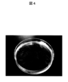
- FIG. 4 is a diagram in which about 20 PLA nanosheets produced by the method of FIG.
- FIG. 5 is a schematic view showing a method of fragmenting lactic acid-glycolic acid copolymer (PLGA) nanosheets by oxygen plasma irradiation and dispersing the fragmented nanosheets.
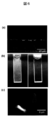
- FIG. 6 is a diagram in which PLGA nanosheets are fragmented by oxygen plasma irradiation and the fragmented nanosheets are dispersed.
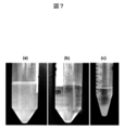
- FIG. 7 is a diagram in which PLA nanosheets are fragmented by a homogenizer and the fragmented nanosheets are dispersed.
- A) is a state in which fragmented PLA nanosheets are dispersed
- (b) is a control of (a) (only pure water), and (c) is precipitated by centrifuging (a).
- FIG. 8 is a diagram showing the relationship between the irradiation time of the homogenizer and the average area per fragmented PLA nanosheet associated therewith.
- FIG. 9 is a diagram showing the relationship between the volume concentration and the number density of fragmented PLA nanosheets.
- FIG. 10 shows freeze-dried fragmented PLA nanosheets and how they are redispersed.
- A) is a freeze-dried body (bulk structure) that is an aggregate of fragmented PLA nanosheets
- (b) is a state in which the dried body of (a) is redispersed in a 1.5 mL tube.
- FIG. 11 is a diagram in which fragmented PLA nanosheets are reconstructed on a SiO 2 substrate as a film-like structure as an aggregate.
- FIG. 12 is a diagram showing the substrate coverage when the fragmented PLA nanosheet is reconstructed on the SiO 2 substrate as a film-like structure that is an aggregate thereof.
- (A) is a diagram showing the relationship between the fragmentation PLA nanosheet volume concentration and substrate coverage of a diagram of the SiO 2 substrate was reconstructed as (b) is film-like structure fragmentation PLA nanosheet.
- FIG. 13 is a diagram showing how fragmented PLA nanosheets are reconstructed on the injection needle, skin model substrate, and mouse skin, respectively.
- A is a view of an injection needle in which a fragmented PLA nanosheet is reconstructed as a film-like structure, observed under visible light
- (b) is a view of (a) observed with a fluorescence stereomicroscope
- (c) is a fragment.
- FIG. 14 is a view showing a state in which a PLA nanosheet is produced on a polyethylene terephthalate (PET) film using a micro gravure method.
- PET polyethylene terephthalate
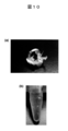
- FIG. 15A is a diagram showing a state in which a PLA nanosheet prepared using a microgravure method is peeled off from a PET film.
- (B) is an enlarged view of (a).
- FIG. 16 is a diagram showing a result of reconstructing a nanosheet using a fragmented PLA nanosheet dispersion in a hole portion formed in Transwell (registered trademark) (manufactured by Corning).
- FIG. 17A is a schematic diagram showing an experimental system for evaluating bacterial permeation inhibiting ability
- FIG. 17B is a diagram showing the evaluation result of bacterial permeation inhibiting ability.
- distributing the fragmented polymer ultrathin film in a liquid medium including the following processes can also be provided.
- the formation of the composite film is preferably performed by alternately laminating the insoluble polymer ultrathin film and the soluble polymer film on a substrate.
- the above-mentioned soluble polymer film (polymer substrate or the like) can also be used as the substrate.
- the order and number of layers of the insoluble polymer ultrathin film laminated on the substrate and the soluble polymer film are not particularly limited and can be arbitrarily set.
- the lamination method is not limited.
- a desired polymer solution is formed into a polymer ultrathin film or polymer film by a known film forming method such as a spin coating method, a cast method, or a microgravure method. Is preferred.
- a spin coating method for example, a desired polymer solution is applied on a substrate at 100 to 1000 rpm for 1 to 10 seconds, and then applied at 1000 to 8000 rpm for 10 to 120 seconds. And heat drying at 20 to 150 ° C. for 60 to 300 seconds.
- the film thickness of the polymer ultrathin film or polymer film on the substrate can be controlled by the concentration of the polymer solution, preferably 1 to 100 mg / mL, more preferably 2 to 50 mg / mL, More preferably, it is 5 to 20 mg / mL. Furthermore, if the rotation speed and rotation time of the spin coater are increased, the film thickness of the polymer ultrathin film or polymer film on the substrate becomes thinner.
- the heating temperature and the heating time are not particularly limited as long as the solvent of the polymer solution after coating is evaporated.
- a lamination method using a roll-to-roll method may be used.
- a base material (soluble polymer film) wound in a roll shape, and a polymer solution (for insoluble ultra-thin polymer film and soluble polymer film) are applied and coated on the base material, respectively.
- the composite film in a state of being wound into a roll can be formed by winding it into a roll while drying and repeating this procedure for the number of times of stacking.
- the insoluble ultra-thin polymer film is finally derived from the ultra-thin polymer film dispersed in the dispersion of the present invention.
- the soluble polymer film material is not limited as long as it can be dissolved in the liquid medium used in the dispersion.
- polyacrylic acid and polyacrylic acid can be used.
- Preferred examples include polyelectrolytes such as methacrylic acid, nonionic water-soluble polymers such as polyethylene glycol, polyacrylamide and polyvinyl alcohol (PVA), and polysaccharides such as starch and cellulose acetate. Among them, PVA is more preferred.
- the composite film formed on the substrate is immersed in a liquid medium. At this time, only a portion of the composite film soluble in the liquid medium is dissolved in the composite film. become.
- the polymer ultrathin film can be separated from the composite film one by one in the liquid medium and can be suspended in the liquid medium.
- the composite film formed on the base material may be once peeled off from the base material and then immersed, or the base material without peeling off the composite film. It may be soaked together and is not limited.
- the polymer ultrathin film is finely fragmented (cut) by irradiating the liquid medium in which the polymer ultrathin film is suspended with high energy. As a result, the ultra-thin polymer film having a fine size is dispersed in the liquid medium, and the dispersion of the present invention can be prepared.
- the method of high-energy irradiation is not limited, but is preferably performed using a known energy irradiation device such as a homogenizer, a microfluidizer, and a sonicator. Among them, a homogenizer and a sonicator are used. It is more preferable. In addition, you may add well-known various dispersing agents (polymer
- a method for preparing a polymer ultrathin film dispersion comprising the following steps, wherein a fragmented polymer ultrathin film is dispersed in a liquid medium.
- a step of immersing the fragmented composite membrane in the medium to dissolve the soluble polymer membrane in the composite membrane and suspend the insoluble polymer ultrathin film in the media Immersion / floating process
- the description regarding the step (1a) described above can be similarly applied.
- the composite film is fragmented in a composite state (laminated state or the like) by performing an etching process on the composite film using a lithography technique.
- “covering the composite film with a predetermined pattern mask” does not mean that the covering mode (procedure) is limited to a specific mode.
- All aspects of covering with a predetermined pattern mask are included. Accordingly, (i) the composite film formed on the base material may be covered with the pattern mask while the composite film is fixed (adhered) to the base material (the pattern mask may then be covered before the etching process).
- the composite film is peeled from the base material), and (ii) the composite film formed on the base material may be covered with the pattern mask after the composite film is first peeled from the base material. Or (iii) forming or placing a pattern mask on the substrate in advance before forming the composite film on the substrate, and then the pattern mask is already in close contact with the composite film when the composite film is formed In this state, the pattern mask and the composite film may be integrally peeled off from the substrate to obtain a composite film covered with the pattern mask. There. In this way, the composite film covered with the predetermined pattern mask is etched and fragmented in the state of the composite film, so that the composite film is immersed in the liquid medium in the step (2c) described later.
- each piece (polymer ultra-thin film) depends on the shape of the pattern mask used, it can be made highly uniform, resulting in a dispersion with better dispersibility.
- the shape of the pattern mask is not limited, but a pattern mask having a regular lattice pattern in the vertical and horizontal directions is preferable.
- the high energy irradiation method is not particularly limited as long as the formed composite film can be etched. For example, oxygen plasma treatment, carbon monoxide plasma treatment, and reactive ion etching using a halogen gas.
- the composite film in addition to the etching process for the composite film described above, the composite film may be fragmented in a composite state (laminated state, etc.) by applying a shearing process to the composite film.
- a shearing process to the composite film.
- the composite film by shearing the composite film using a cutter-like or shredder-like blade, or scratching with a needle-like or comb-like object, only the composite film or the ultra-thin film has a desired shape and Can be fragmented to size.
- a roll-to-roll method for example, a comb-shaped cutter is applied to the moving composite film so that the composite film can be efficiently cut by continuous operation.
- the ultra-thin polymer dispersion of the present invention is, for example, an ultra-thin polymer dispersion in which a fragmented ultra-thin polymer film is dispersed in a liquid medium, and (i) the ultra-thin polymer dispersion
- the film thickness of the thin film is 500 nm or less and the length of the longest axis is 5 mm or less, and / or (ii) the polymer ultrathin film having a film thickness of 500 nm or less and a film area of 25 mm 2 or less.
- a thin film dispersion is preferred.
- the film thickness of the ultra-thin polymer film is 500 nm or less, preferably 5 nm to 500 nm, more preferably 10 nm to 200 nm, and still more preferably 15 nm to 100 nm.
- the film thickness of the ultra-thin polymer film is within the above range, it is preferable in that high adhesiveness is exhibited when reconstructing at the interface.
- the length of the longest axis of the ultra-thin polymer film is 5 mm or less, preferably 1 ⁇ m to 5 mm, more preferably 5 ⁇ m to 1 mm, and still more preferably 50 ⁇ m to 500 ⁇ m.
- the “length of the longest axis” is the length of the portion forming the maximum width in the ultra-thin polymer film.
- the film area of the ultra-thin polymer film is 25 mm 2 or less, and preferably 0.5 ⁇ m 2 to 25 mm 2 .
- the film area of the ultra-thin polymer film is preferably within the above range because it can adhere to an interface having a complicated shape.
- the ultra-thin polymer dispersion of the present invention is, for example, a super-thin polymer dispersion in which a fragmented ultra-thin polymer film is dispersed in a liquid medium, from the dispersion to the liquid medium.
- a super-thin polymer dispersion in which a fragmented ultra-thin polymer film is dispersed in a liquid medium, from the dispersion to the liquid medium.
- the individual shape of the polymer ultrathin film in the dispersion of the present invention is not limited, but preferred examples include a circular shape, a polygonal shape, an elliptical shape, a ribbon shape, a string shape, a multi-branched shape, and a star shape.
- the liquid medium in the dispersion of the present invention is not limited, but is preferably, for example, an aqueous medium. Specifically, water, water in which a salt is dissolved, water in which a surfactant is dissolved, buffer solution
- the solvent should be selected so as not to dissolve the polymer ultrathin film described above.
- the material of the polymer constituting the ultrathin film in the dispersion of the present invention is not limited.
- polylactic acid represented by biodegradable polymer
- Lactic acid-glycolic acid copolymer PLGA
- polycaprolactone PCL
- polyethylene polypropylene
- polystyrene polyethylene terephthalate
- polyvinyl chloride polymethyl methacrylate and polycarbonate represented by general-purpose polymers
- rubber-based Preferable examples include polyvinyl acetate, polyisoprene, polybutadiene, polychloroprene and polysiloxane represented by polymers.
- the concentration of the ultra-thin polymer film contained in the dispersion of the present invention is not limited, but is preferably, for example, 1 to 100 mg / mL, more preferably 2 to 50 mg / mL, and even more preferably 5 ⁇ 20 mg / mL.
- concentration of the ultra-thin polymer film is within the above range, it is preferable from the viewpoint of the reconstructability of the patchwork-like film structure.
- Polymer ultra-thin film assembly The polymer ultra-thin film assembly of the present invention is, for example, a collection of fragmented polymer ultra-thin films, and at least some of the polymer ultra-thin films overlap each other. The film-like structure formed is mentioned.
- Such an aggregate can be obtained, for example, by drying the ultra-thin polymer dispersion of the present invention described above to remove the liquid medium in the dispersion.
- the form of the aggregate of the present invention is not limited to the above-described film-like structure, and may be, for example, one having a lump shape (lump structure). Note that (i) the film thickness and the length of the longest axis, and (ii) the film thickness and film area of the ultra-thin polymer film constituting the aggregate of the present invention are as described in 1. above. Those in the numerical range described in the section are preferable.
- the above-mentioned film-like structure is an aspect in which at least a part of the polymer ultrathin films that are fragmented overlap each other on an arbitrary substrate (base) (at least a part follows the adjacent polymer ultrathin films) In a sheet form).
- a large number of fragmented ultra-thin polymer films are in close contact with each other in the form of a patchwork and can function as a single film as a whole (for example, FIG. 11 (a) to (d) )reference).
- each individual ultra-thin polymer film that becomes a constituent component is adsorbed onto the substrate by physical adsorption (interface adsorption), and a huge van der Waals force acts as a whole.
- this film-like structure is formed by an infinite number of fragmented fine polymer ultra-thin films spread in a sheet shape, and thus the thickness of the entire film is very high.
- the hole (The thing of the hole diameter of the grade which cannot be visually recognized with the naked eye) which consists of a clearance gap between polymer ultrathin films may exist, and is not limited.
- the above-described massive structure may be any structure in which individual polymer ultrathin films are gathered in an arbitrary shape and formed into one massive shape, for example, when there is no arbitrary substrate as described above, There is no particular limitation.
- the drying method for obtaining the aggregate of the present invention is not limited, but preferred examples include freeze drying, vacuum drying, airflow drying, rotary drying, stirring drying, and spray drying. Among them, freeze drying, Vacuum drying and spray drying are more preferred. These various drying methods can be carried out by conventional methods. Moreover, it is preferable that the said drying is performed with respect to this dispersion, after apply
- the polymer ultrathin film once formed on the substrate is cut (sheared) by scratching with a blade such as a cutter or a needle-like or comb-like instrument, and then peeled off from the substrate, A fragmented polymer ultrathin film can be obtained.
- a rubber-like substrate (rubber plate) is preferably used as the substrate. After the cutting process, the rubber plate is repeatedly expanded and contracted to lift the polymer ultrathin film, which is normally difficult to peel off, from the rubber plate, thereby recovering the fragmented polymer ultrathin film.
- the ultra-thin polymer dispersion of the present invention can be obtained by, for example, forming a thin film and fragmenting even a polymer that is insoluble in an aqueous solvent. It can be easily dispersed in a solvent. Therefore, the ultra-thin polymer dispersion according to the present invention and the ultra-thin polymer aggregate obtained by drying the dispersion are unprecedented types of cosmetic materials, transdermal absorption materials (such as ointments), hemostasis and adhesion for surgical operations. It can also be applied to prevention materials, tissue regeneration engineering materials, and the like, and can be blended in various pharmaceuticals, quasi drugs, cosmetics (cosmetics), foods, medical devices, and the like.
- the dispersion and aggregate of the present invention can be used for various uses such as in the medical field. Therefore, the present invention provides a cosmetic material, a percutaneous absorption material, a hemostasis and adhesion prevention material for surgery, and a material for tissue regeneration engineering, comprising the ultra-thin polymer dispersion and / or the ultra-thin polymer aggregate.
- various pharmaceuticals, quasi-drugs, cosmetics (cosmetics), foods, medical devices and the like including the dispersion and / or aggregate can also be provided.
- the sheet-like ultrathin polymer aggregate reconstructed from the above dispersion is a very close membrane, and has, for example, the property of being excellent in permeation inhibiting ability and permeation inhibiting ability of bacteria and microorganisms.
- it can be applied to medical uses such as a wound dressing material, a wound protection material, and a perforated portion occlusion material. Therefore, the present invention can also provide a wound dressing material, a wound protection material, a perforated portion occlusion material, and the like including the polymer ultra-thin film assembly.
- the polymer ultra-thin film dispersion and polymer ultra-thin film assembly of the present invention are polymer paints that are soluble only in an organic solvent, the polymer can be dispersed in an aqueous solvent. And it can mix
- the polymer ultrathin film dispersion of the present invention since the fragmented polymer ultrathin film (in a dry state) obtained from the polymer ultrathin film aggregate can be easily dispersed again in an aqueous medium, the polymer ultrathin film dispersion of the present invention It can be used for the same applications as Hereinafter, the present invention will be described more specifically with reference to examples. However, the present invention is not limited to these examples. In the following examples, “polymer ultrathin film” in the present invention may be referred to as “nanosheet”.
- PLA polylactic acid
- PLGA lactic acid-glycolic acid copolymer
- PCL polycaprolactone
- a resist pattern (OFPR-800, 510 cp; 5 ⁇ m ⁇ 10 ⁇ m rectangle) was formed on a Teflon (registered trademark) substrate (2 ⁇ 2 cm) by photolithography.
- a PVA aqueous solution (100 mg / mL) was repeatedly spin-coated (600 rpm, 10 sec) and dried (70 ° C., 120 sec).
- a PVA aqueous solution (100 mg / mL) and a PLGA solution (10 mg / mL) were spin-coated (4000 rpm, 20 sec) in this order.
- PVA / PLGA composite film This operation was repeated 10 times to produce a PVA / PLGA alternating laminated film (PVA / PLGA composite film). Further, an aqueous PVA solution (100 mg / mL) was spin-coated (600 rpm, 10 sec), dried to form a PVA support film (70 ° C., 120 sec), and then peeled off from the Teflon (registered trademark) substrate together with the laminated film. .
- Fragmentation (cutting) of thin film by turning the back side (resist pattern side) of the peeled PVA / PLGA alternating laminated film face up and etching by oxygen plasma irradiation (200 w, 120 sec) to remove regions other than the resist pattern ) Finally, after dissolving the PVA layer of the laminated film in pure water, the resist pattern was removed by centrifugation (100 g, 5 min), and the fragmented PLGA nanosheets were recovered as a dispersion. The laminated film after the oxygen plasma irradiation was coated with osmium tetroxide, and then the cut surface was observed with a scanning electron microscope (HITACHI S-4500, 10 kV).
- HITACHI S-4500 scanning electron microscope
- PLA powder PLA of about 8 mg
- a homogenizer 33000 rpm
- precipitation occurred immediately upon standing FIG. 7B
- the obtained fragmented PLA nanosheet could be purified and concentrated by centrifugation (3000 rpm, 10 min) (FIG. 7 (c)).
- the fragmented PLA nanosheet dispersion after pulverization and stirring (33,000 rpm, 1 to 10 min) was dropped onto a SiO 2 substrate (10 ⁇ L) and dried.
- the adsorption site exhibited a structural color derived from the nanosheet (FIG. 12B).
- FIG. 12A shows that the substrate coverage of the nanosheet was measured with a stereomicroscope, it increased depending on the concentration of the dispersion, and reached saturation at 0.32 mg / mL or more (coverage: 88.4%) (FIG. 12A). ).
- a 100 mg / mL PVA aqueous solution was spin-coated on a SiO 2 substrate (4 cm ⁇ 4 cm, 5 sheets) (4000 rpm, 20 sec) and dried by heating (70 ° C., 1 min).
- a 10 mg / mL PLA solution in which octadecyl rhodamine (200 M), a hydrophobic fluorescent probe, is dissolved in advance is spin-coated (4000 rpm, 20 sec), dried by heating (70 ° C., 1 min), and a rhodamine-labeled PLA nanosheet is produced. did.
- Example 4 This operation was repeated 10 times to produce a PVA / PLA alternating laminated film (PVA / PLA composite film).
- a rhodamine-labeled fragmented PLA nanosheet was obtained.
- a drawer operation similar to that in Example 7 was attempted using an 18G injection needle (metal) and an artificial leather substrate (urethane resin) as a skin model. In both cases, the adsorption of the fragmented PLA nanosheets was not visible under visible light.
- the lower body of the mouse was immersed in a fragmented PLA nanosheet dispersion (0.32 mg / mL) and pulled out for adsorption.
- adsorption site was observed with an in vivo living body observation system (OV110, Olympus Corporation), the adsorption was not visible under visible light (FIG. 13 (e)), but only the immersion site was observed under a fluorescence microscope. Light was emitted uniformly, and a film-like structure as an aggregate of fragmented PLA nanosheets was confirmed (FIG. 13 (g)). In particular, the film-like structure was covered even between the fingers and the entire nail. On the other hand, no light was emitted before adsorption (FIG. 13 (f)).
- OV110 in vivo living body observation system
- the film thickness was 35 ⁇ 2 nm (measured with a stylus pressure gauge). Moreover, if this PVA / PLA alternating lamination film
- FBS fetal bovine serum
- Pseudomonas aeruginosa Pseudomonas aeruginosa
- a polymer ultrathin film dispersion in which a fragmented polymer ultrathin film is dispersed in a liquid medium, a method for preparing the polymer ultrathin film, and a polymer ultrathin film aggregate obtained by drying the dispersion are provided.
- the ultra-thin polymer dispersion of the present invention is useful in that, for example, even a polymer that is insoluble in an aqueous solvent can be dispersed in the solvent by forming it into a thin film and fragmenting it. .
- the polymer ultra-thin film dispersion and polymer ultra-thin film assembly of the present invention are an unprecedented type of cosmetic material, percutaneous absorption material (such as an ointment), surgical hemostasis and adhesion prevention material, tissue regeneration. It can also be applied to engineering materials and the like, and can be blended in pharmaceuticals, quasi drugs, cosmetics (cosmetics), foods, medical devices, and the like.
- the dispersion and aggregate of the present invention are extremely practical in that they can be expected to contribute to applications in the medical field and the like.
- the dispersion and aggregate of the present invention can be dispersed in an aqueous solvent by forming the polymer into a thin film and fragmenting it even if it is a polymer paint that is soluble only in an organic solvent. It is also excellent in practicality in that it can be used by being blended with industrial products such as paints and coating agents.
Landscapes
- Chemical & Material Sciences (AREA)
- Dispersion Chemistry (AREA)
- Health & Medical Sciences (AREA)
- Chemical Kinetics & Catalysis (AREA)
- Medicinal Chemistry (AREA)
- Polymers & Plastics (AREA)
- Organic Chemistry (AREA)
- Manufacture Of Macromolecular Shaped Articles (AREA)
- Processes Of Treating Macromolecular Substances (AREA)
Abstract
本発明は、高分子が不溶性の溶媒に対しても自発的に分散し得る高分子分散体として、断片化された高分子超薄膜が液状媒体中に分散してなる高分子超薄膜分散体を提供する。本発明の高分子超薄膜分散体は、断片化された高分子超薄膜が液状媒体中に分散してなるものであり、(a) 基材上に、前記媒体に不溶性の高分子超薄膜と前記媒体に可溶性の高分子膜との複合膜を形成する工程;(b) 前記複合膜を前記媒体中に浸漬させて、当該複合膜中の前記可溶性の高分子膜を溶解させることで、前記不溶性の高分子超薄膜を当該媒体中に浮遊させる工程;及び(c) 前記媒体に高エネルギー照射をして、当該媒体中に浮遊している不溶性の高分子超薄膜を断片化する工程により得られるものである。
Description
本発明は、断片化された高分子超薄膜の分散体及びその調製方法、並びに断片化された高分子超薄膜の集合体に関する。詳しくは、断片化された高分子超薄膜を液体に分散させてなる断片化高分子超薄膜分散体、及びその調製方法、並びに、当該分散体を乾燥させて得られる断片化高分子超薄膜集合体に関する。
有機分子の薄膜の調製方法としては、従来よりスピンコート法、電解重合法、蒸着法及び蒸着重合法などが用いられている。また、配向膜を得る方法としてはLangmuir−Blodgett(LB)法が良く知られている。この方法は、両親媒性分子を揮発性有機溶媒に溶解させて気−液界面上に展開し、溶媒を蒸発後圧縮して得られた単分子膜を固体基板上に移し取る方法であり、薄膜の層数や積層順序を制御することができる。
さらに、薄膜状の高分子構造体の調製方法として、例えばマイクロリソグラフィーの技術により得られたパターン状の金基体に自己組織化単分子膜を形成後、多官能性分子としてアルブミンを吸着し架橋させた後、アルブミン重合体薄膜を当該金基体から剥離させる方法(WO 2006/025592参照)や、基体上に高分子電解質を交互積層させて吸着させ高分子超薄膜を形成し、形成した薄膜を基体から剥離して基体と同じサイズの高分子超薄膜を調製する方法が知られている。
ところで、従来、所定の溶媒に不溶性の高分子は、粉末状にしたものであっても該溶媒に自発的に分散し得ないものが多く、分散促進剤など他の成分を添加しなければ該高分子の分散体を得ることは困難であった。
さらに、薄膜状の高分子構造体の調製方法として、例えばマイクロリソグラフィーの技術により得られたパターン状の金基体に自己組織化単分子膜を形成後、多官能性分子としてアルブミンを吸着し架橋させた後、アルブミン重合体薄膜を当該金基体から剥離させる方法(WO 2006/025592参照)や、基体上に高分子電解質を交互積層させて吸着させ高分子超薄膜を形成し、形成した薄膜を基体から剥離して基体と同じサイズの高分子超薄膜を調製する方法が知られている。
ところで、従来、所定の溶媒に不溶性の高分子は、粉末状にしたものであっても該溶媒に自発的に分散し得ないものが多く、分散促進剤など他の成分を添加しなければ該高分子の分散体を得ることは困難であった。
そこで、本発明が解決しようとする課題は、高分子が不溶性の溶媒に対しても自発的に分散し得る高分子分散体として、断片化された高分子超薄膜が液状媒体中に分散してなる高分子超薄膜分散体を提供すること、及びその調製方法を提供することにある。さらに、本発明は、当該分散体を乾燥させた集合体(例えば膜状のもの)を提供することを目的とする。
本発明者は、上記課題を解決するべく鋭意検討を行い、本発明を完成した。
すなわち、本発明は以下の通りである。
(1)断片化された高分子超薄膜が液状媒体中に分散してなる高分子超薄膜分散体であって、以下の工程:
(a)基材上に、前記媒体に不溶性の高分子超薄膜と前記媒体に可溶性の高分子膜との複合膜を形成する工程;
(b)前記複合膜を前記媒体中に浸漬させて、当該複合膜中の前記可溶性の高分子膜を溶解させることで、前記不溶性の高分子超薄膜を当該媒体中に浮遊させる工程;及び
(c)前記媒体に高エネルギー照射をして、当該媒体中に浮遊している不溶性の高分子超薄膜を断片化する工程
により得られる、前記分散体。
上記(1)の分散体においては、前記高エネルギー照射は、例えば、ホモジナイザー、マイクロフルイダイザー及びソニケーターからなる群より選ばれる少なくとも1つを用いて行われるものが挙げられる。
(2)断片化された高分子超薄膜が液状媒体中に分散してなる高分子超薄膜分散体であって、以下の工程:
(a)基材上に、前記媒体に不溶性の高分子超薄膜と可溶性の高分子膜との複合膜を形成する工程;
(b)前記複合膜を所定のパターンマスクで覆った後、高エネルギー照射によるエッチング処理をし、又は前記複合膜を剪断処理して、当該複合膜を断片化する工程;及び
(c)前記断片化後の複合膜を前記媒体中に浸漬させて、当該複合膜中の前記可溶性の高分子膜を溶解させることで、前記不溶性の高分子超薄膜を当該媒体中に浮遊させる工程
により得られる、前記分散体。
上記(2)の分散体においては、前記高エネルギー照射は、例えば、酸素プラズマ、電子線又はマイクロ波からなる群より選ばれる少なくとも1つを用いて行われるものが挙げられる。
上記(1)及び(2)の分散体において、前記液状媒体としては、例えば水性媒体が挙げられる。
上記(1)及び(2)の分散体において、前記工程(a)における複合膜の形成は、例えば、前記媒体に不溶性の高分子超薄膜と前記媒体に可溶性の高分子膜とを、前記基材上に交互に積層させることにより行われるものが挙げられる。ここで、前記積層としては、例えば、スピンコーティング法、キャスト法又はマイクログラビア法で行われるものが挙げられる。
(3)断片化された高分子超薄膜が液状媒体中に分散してなる高分子超薄膜分散体であって、該分散体は、前記媒体が除去されることにより、前記超薄膜の少なくとも一部が互いに重複してなる膜状構造物を構築し得るものである、前記分散体。
(4)断片化された高分子超薄膜が液状媒体中に分散してなる高分子超薄膜分散体であって、前記高分子は、膜厚が500nm以下かつ膜面積が25mm2以下である、前記分散体。
(5)断片化された高分子超薄膜が集合してなる高分子超薄膜集合体であって、該集合体は、前記高分子の少なくとも一部が互いに重複してなる膜状構造物である、前記集合体。
上記(5)の集合体としては、例えば、膜厚が500nm以下かつ膜面積が25mm2以下であるものが挙げられる。
(6)上記(1)~(4)のいずれかに記載の分散体を乾燥させて得られる高分子超薄膜集合体。
上記(6)の集合体においては、前記乾燥は、例えば、凍結乾燥、真空乾燥、気流乾燥、回転乾燥、攪拌乾燥及び噴霧乾燥からなる群より選ばれる少なくとも1つにより行われるものが挙げられる。また、前記乾燥は、例えば、塗布若しくは噴霧後の前記分散体に対して、又は前記分散体から掬い取った高分子超薄膜に対して行われるものが挙げられる。
上記(6)の集合体は、例えば、膜状又は塊状の構造物が挙げられる。
上記(6)の集合体は、例えば、液状媒体中において高分子超薄膜の分散体として分散し得るものが挙げられる。
(7)断片化された高分子超薄膜が液状媒体中に分散してなる高分子超薄膜分散体の調製方法であって、以下の工程:
(a)基材上に、前記媒体に不溶性の高分子超薄膜と前記媒体に可溶性の高分子膜との複合膜を形成する工程;
(b)前記複合膜を前記媒体中に浸漬させて、当該複合膜中の前記可溶性の高分子膜を溶解させることで、前記不溶性の高分子超薄膜を当該媒体中に浮遊させる工程;及び
(c)前記媒体に高エネルギー照射をして、当該媒体中に浮遊している不溶性の高分子超薄膜を断片化する工程
を含む、前記方法。
上記(7)の方法において、前記高エネルギー照射は、例えば、ホモジナイザー、マイクロフルイダイザー及びソニケーターからなる群より選ばれる少なくとも1つを用いて行うことができる。
(8)断片化された高分子超薄膜が液状媒体中に分散してなる高分子超薄膜分散体の調製方法であって、以下の工程:
(a)基材上に、前記媒体に不溶性の高分子超薄膜と可溶性の高分子膜との複合膜を形成する工程;
(b)前記複合膜を所定のパターンマスクで覆った後、高エネルギー照射によるエッチング処理をし、又は前記複合膜を剪断処理して、当該複合膜を断片化する工程;及び
(c)前記断片化後の複合膜を前記媒体中に浸漬させて、当該複合膜中の前記可溶性の高分子膜を溶解させることで、前記不溶性の高分子超薄膜を当該媒体中に浮遊させる工程
を含む、前記方法。
上記(8)の方法において、前記高エネルギー照射は、例えば、酸素プラズマにより行うことができる。
上記(7)及び(8)の方法において、前記液状媒体としては、例えば水性媒体が挙げられる。
上記(7)及び(8)の方法において、工程(a)における前記複合膜の形成は、例えば、前記媒体に不溶性の高分子超薄膜と前記媒体に可溶性の高分子膜とを、前記基材上に交互に積層させることにより行うことができる。ここで、前記積層は、例えば、スピンコーティング法、キャスト法又はマイクログラビア法で行うことができる。
本発明者は、上記課題を解決するべく鋭意検討を行い、本発明を完成した。
すなわち、本発明は以下の通りである。
(1)断片化された高分子超薄膜が液状媒体中に分散してなる高分子超薄膜分散体であって、以下の工程:
(a)基材上に、前記媒体に不溶性の高分子超薄膜と前記媒体に可溶性の高分子膜との複合膜を形成する工程;
(b)前記複合膜を前記媒体中に浸漬させて、当該複合膜中の前記可溶性の高分子膜を溶解させることで、前記不溶性の高分子超薄膜を当該媒体中に浮遊させる工程;及び
(c)前記媒体に高エネルギー照射をして、当該媒体中に浮遊している不溶性の高分子超薄膜を断片化する工程
により得られる、前記分散体。
上記(1)の分散体においては、前記高エネルギー照射は、例えば、ホモジナイザー、マイクロフルイダイザー及びソニケーターからなる群より選ばれる少なくとも1つを用いて行われるものが挙げられる。
(2)断片化された高分子超薄膜が液状媒体中に分散してなる高分子超薄膜分散体であって、以下の工程:
(a)基材上に、前記媒体に不溶性の高分子超薄膜と可溶性の高分子膜との複合膜を形成する工程;
(b)前記複合膜を所定のパターンマスクで覆った後、高エネルギー照射によるエッチング処理をし、又は前記複合膜を剪断処理して、当該複合膜を断片化する工程;及び
(c)前記断片化後の複合膜を前記媒体中に浸漬させて、当該複合膜中の前記可溶性の高分子膜を溶解させることで、前記不溶性の高分子超薄膜を当該媒体中に浮遊させる工程
により得られる、前記分散体。
上記(2)の分散体においては、前記高エネルギー照射は、例えば、酸素プラズマ、電子線又はマイクロ波からなる群より選ばれる少なくとも1つを用いて行われるものが挙げられる。
上記(1)及び(2)の分散体において、前記液状媒体としては、例えば水性媒体が挙げられる。
上記(1)及び(2)の分散体において、前記工程(a)における複合膜の形成は、例えば、前記媒体に不溶性の高分子超薄膜と前記媒体に可溶性の高分子膜とを、前記基材上に交互に積層させることにより行われるものが挙げられる。ここで、前記積層としては、例えば、スピンコーティング法、キャスト法又はマイクログラビア法で行われるものが挙げられる。
(3)断片化された高分子超薄膜が液状媒体中に分散してなる高分子超薄膜分散体であって、該分散体は、前記媒体が除去されることにより、前記超薄膜の少なくとも一部が互いに重複してなる膜状構造物を構築し得るものである、前記分散体。
(4)断片化された高分子超薄膜が液状媒体中に分散してなる高分子超薄膜分散体であって、前記高分子は、膜厚が500nm以下かつ膜面積が25mm2以下である、前記分散体。
(5)断片化された高分子超薄膜が集合してなる高分子超薄膜集合体であって、該集合体は、前記高分子の少なくとも一部が互いに重複してなる膜状構造物である、前記集合体。
上記(5)の集合体としては、例えば、膜厚が500nm以下かつ膜面積が25mm2以下であるものが挙げられる。
(6)上記(1)~(4)のいずれかに記載の分散体を乾燥させて得られる高分子超薄膜集合体。
上記(6)の集合体においては、前記乾燥は、例えば、凍結乾燥、真空乾燥、気流乾燥、回転乾燥、攪拌乾燥及び噴霧乾燥からなる群より選ばれる少なくとも1つにより行われるものが挙げられる。また、前記乾燥は、例えば、塗布若しくは噴霧後の前記分散体に対して、又は前記分散体から掬い取った高分子超薄膜に対して行われるものが挙げられる。
上記(6)の集合体は、例えば、膜状又は塊状の構造物が挙げられる。
上記(6)の集合体は、例えば、液状媒体中において高分子超薄膜の分散体として分散し得るものが挙げられる。
(7)断片化された高分子超薄膜が液状媒体中に分散してなる高分子超薄膜分散体の調製方法であって、以下の工程:
(a)基材上に、前記媒体に不溶性の高分子超薄膜と前記媒体に可溶性の高分子膜との複合膜を形成する工程;
(b)前記複合膜を前記媒体中に浸漬させて、当該複合膜中の前記可溶性の高分子膜を溶解させることで、前記不溶性の高分子超薄膜を当該媒体中に浮遊させる工程;及び
(c)前記媒体に高エネルギー照射をして、当該媒体中に浮遊している不溶性の高分子超薄膜を断片化する工程
を含む、前記方法。
上記(7)の方法において、前記高エネルギー照射は、例えば、ホモジナイザー、マイクロフルイダイザー及びソニケーターからなる群より選ばれる少なくとも1つを用いて行うことができる。
(8)断片化された高分子超薄膜が液状媒体中に分散してなる高分子超薄膜分散体の調製方法であって、以下の工程:
(a)基材上に、前記媒体に不溶性の高分子超薄膜と可溶性の高分子膜との複合膜を形成する工程;
(b)前記複合膜を所定のパターンマスクで覆った後、高エネルギー照射によるエッチング処理をし、又は前記複合膜を剪断処理して、当該複合膜を断片化する工程;及び
(c)前記断片化後の複合膜を前記媒体中に浸漬させて、当該複合膜中の前記可溶性の高分子膜を溶解させることで、前記不溶性の高分子超薄膜を当該媒体中に浮遊させる工程
を含む、前記方法。
上記(8)の方法において、前記高エネルギー照射は、例えば、酸素プラズマにより行うことができる。
上記(7)及び(8)の方法において、前記液状媒体としては、例えば水性媒体が挙げられる。
上記(7)及び(8)の方法において、工程(a)における前記複合膜の形成は、例えば、前記媒体に不溶性の高分子超薄膜と前記媒体に可溶性の高分子膜とを、前記基材上に交互に積層させることにより行うことができる。ここで、前記積層は、例えば、スピンコーティング法、キャスト法又はマイクログラビア法で行うことができる。
図1は、ポリ乳酸(PLA)の高分子超薄膜(ナノシート)をSiO2基板上に作製後、その上に形成されたポリビニルアルコール(PVA)にて剥離させ、水中でPVA膜を溶解させてPLAナノシートを浮遊させる方法を示す模式図である。
図2は、得られたPLAナノシートの図である。(a)はPVA膜を用いてPLAナノシートを剥離する様子を示した図であり、(b)はPLA/PVA複合膜を純水に浸漬させてPVAを溶解させ、PLAナノシートを浮遊させた図であり、(c)はPLAナノシートを金属枠に掬い取り乾燥させた図である。
図3は、PVA/PLA交互積層膜(PVA/PLA複合膜)を利用してPLAナノシートを大量調製する方法を示す模式図である。
図4は、図3の方法で作製したPLAナノシートが純粋中に20枚程度浮遊している図である。
図5は、乳酸−グリコール酸共重合体(PLGA)ナノシートの酸素プラズマ照射による断片化し、断片化ナノシートを分散させる方法を示す模式図である。
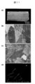
図6は、PLGAナノシートを酸素プラズマ照射によって断片化し、断片化ナノシートを分散させた図である。(a)は酸素プラズマ照射によってPLGAナノシートを断片化した後の断面を走査型電子顕微鏡像、(b)は断片化したPLGAナノシートをキュベットに分散させた図(左)とその対照(純水のみ)を示す図であり、(c)は断片化したPLGAナノシートの走査型電子顕微鏡像である。
図7は、PLAナノシートをホモジナイザーによって断片化し、断片化ナノシートを分散させた図である。(a)は断片化したPLAナノシートが分散している様子であり、(b)は(a)の対照(純水のみ)であり、(c)は(a)を遠心分離させて沈殿させた図である。
図8は、ホモジナイザーの照射時間とそれに伴う断片化PLAナノシート1枚あたりの平均面積の関係を示す図である。
図9は、断片化PLAナノシートの体積濃度と枚数濃度との関係を示す図である。
図10は、凍結乾燥させた断片化PLAナノシートと、それを再分散させた様子とを示す図である。(a)は断片化PLAナノシートの集合体である凍結乾燥体(塊状構造物)であり、(b)は1.5mLチューブに(a)の乾燥体を再分散させた様子である。
図11は、断片化PLAナノシートをその集合体である膜状構造物としてSiO2基板へ再構築させた図である。(a)は断片化PLAナノシートを膜状構造物として再構築させたSiO2基板の図、(b)及び(c)は(a)を高精細マイクロスコープで観察した図、(d)は(a)の走査型電子顕微鏡像である。
図12は、断片化PLAナノシートをその集合体である膜状構造物としてSiO2基板に再構築させたときの基板被覆率を示す図である。(a)は断片化PLAナノシートの体積濃度と基板被覆率との関係を示す図であり、(b)は断片化PLAナノシートを膜状構造物として再構築させたSiO2基板の図である。
図13は、断片化PLAナノシートを注射針、皮膚モデル基板及びマウス皮膚にそれぞれ再構築させた様子を示す図である。(a)は断片化PLAナノシートを膜状構造物として再構築させた注射針を可視光下で観察した図、(b)は(a)を蛍光実体顕微鏡で観察した図、(c)は断片化PLAナノシートを膜状構造物として再構築させた皮膚モデル基板を可視光下で観察した図、(d)は(c)を蛍光実体顕微鏡で観察した図、(e)は下半身を脱毛させたマウスの図、(f)は断片化PLAナノシートを膜状構造物として再構築する前のマウス下半身の図、(g)は断片化PLAナノシートを膜状構造物として再構築させた後のマウス下半身の図である。
図14は、マイクログラビア法を用いてポリエチレンテレフタラート(PET)フィルム上にPLAナノシートを作製した様子を示す図である。
図15は、(a)はマイクログラビア法を用いて作製したPLAナノシートをPETフィルム上から剥離する様子を示す図である。(b)は(a)の拡大図である。
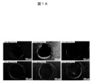
図16は、Transwell(登録商標)(Corning製)に開けた穴の部分に、断片化PLAナノシート分散体を用いてナノシートを再構築し結果を示す図である。
図17は、(a)は細菌透過阻害能の評価を行うための実験系を示す模式図であり、(b)は細菌透過阻害能の評価結果を示す図である。
図2は、得られたPLAナノシートの図である。(a)はPVA膜を用いてPLAナノシートを剥離する様子を示した図であり、(b)はPLA/PVA複合膜を純水に浸漬させてPVAを溶解させ、PLAナノシートを浮遊させた図であり、(c)はPLAナノシートを金属枠に掬い取り乾燥させた図である。
図3は、PVA/PLA交互積層膜(PVA/PLA複合膜)を利用してPLAナノシートを大量調製する方法を示す模式図である。
図4は、図3の方法で作製したPLAナノシートが純粋中に20枚程度浮遊している図である。
図5は、乳酸−グリコール酸共重合体(PLGA)ナノシートの酸素プラズマ照射による断片化し、断片化ナノシートを分散させる方法を示す模式図である。
図6は、PLGAナノシートを酸素プラズマ照射によって断片化し、断片化ナノシートを分散させた図である。(a)は酸素プラズマ照射によってPLGAナノシートを断片化した後の断面を走査型電子顕微鏡像、(b)は断片化したPLGAナノシートをキュベットに分散させた図(左)とその対照(純水のみ)を示す図であり、(c)は断片化したPLGAナノシートの走査型電子顕微鏡像である。
図7は、PLAナノシートをホモジナイザーによって断片化し、断片化ナノシートを分散させた図である。(a)は断片化したPLAナノシートが分散している様子であり、(b)は(a)の対照(純水のみ)であり、(c)は(a)を遠心分離させて沈殿させた図である。
図8は、ホモジナイザーの照射時間とそれに伴う断片化PLAナノシート1枚あたりの平均面積の関係を示す図である。
図9は、断片化PLAナノシートの体積濃度と枚数濃度との関係を示す図である。
図10は、凍結乾燥させた断片化PLAナノシートと、それを再分散させた様子とを示す図である。(a)は断片化PLAナノシートの集合体である凍結乾燥体(塊状構造物)であり、(b)は1.5mLチューブに(a)の乾燥体を再分散させた様子である。
図11は、断片化PLAナノシートをその集合体である膜状構造物としてSiO2基板へ再構築させた図である。(a)は断片化PLAナノシートを膜状構造物として再構築させたSiO2基板の図、(b)及び(c)は(a)を高精細マイクロスコープで観察した図、(d)は(a)の走査型電子顕微鏡像である。
図12は、断片化PLAナノシートをその集合体である膜状構造物としてSiO2基板に再構築させたときの基板被覆率を示す図である。(a)は断片化PLAナノシートの体積濃度と基板被覆率との関係を示す図であり、(b)は断片化PLAナノシートを膜状構造物として再構築させたSiO2基板の図である。
図13は、断片化PLAナノシートを注射針、皮膚モデル基板及びマウス皮膚にそれぞれ再構築させた様子を示す図である。(a)は断片化PLAナノシートを膜状構造物として再構築させた注射針を可視光下で観察した図、(b)は(a)を蛍光実体顕微鏡で観察した図、(c)は断片化PLAナノシートを膜状構造物として再構築させた皮膚モデル基板を可視光下で観察した図、(d)は(c)を蛍光実体顕微鏡で観察した図、(e)は下半身を脱毛させたマウスの図、(f)は断片化PLAナノシートを膜状構造物として再構築する前のマウス下半身の図、(g)は断片化PLAナノシートを膜状構造物として再構築させた後のマウス下半身の図である。
図14は、マイクログラビア法を用いてポリエチレンテレフタラート(PET)フィルム上にPLAナノシートを作製した様子を示す図である。
図15は、(a)はマイクログラビア法を用いて作製したPLAナノシートをPETフィルム上から剥離する様子を示す図である。(b)は(a)の拡大図である。
図16は、Transwell(登録商標)(Corning製)に開けた穴の部分に、断片化PLAナノシート分散体を用いてナノシートを再構築し結果を示す図である。
図17は、(a)は細菌透過阻害能の評価を行うための実験系を示す模式図であり、(b)は細菌透過阻害能の評価結果を示す図である。
以下、本発明を詳細に説明する。本発明の範囲はこれらの説明に拘束されることはなく、以下の例示以外についても、本発明の趣旨を損なわない範囲で適宜変更し実施し得る。なお、本明細書は、本願優先権主張の基礎となる特願2009−236630号明細書(2009年10月13日出願)の全体を包含する。また、本明細書において引用された全ての刊行物、例えば先行技術文献、及び公開公報、特許公報その他の特許文献は、参照として本明細書に組み込まれる。
1.高分子超薄膜分散体
本発明の高分子超薄膜分散体は、断片化された(裁断された)高分子超薄膜が液状媒体中に分散してなるものであり、具体的には、以下の工程により得られるものが挙げられる。なお、本発明においては、以下の工程を含む、断片化された高分子超薄膜が液状媒体中に分散してなる高分子超薄膜分散体の調製方法も提供され得る。
(1a)基材上に、前記媒体に不溶性の高分子超薄膜と前記媒体に可溶性の高分子膜との複合膜を形成する工程(複合膜形成工程)
(1b)前記複合膜を前記媒体中に浸漬させて、当該複合膜中の前記可溶性の高分子膜を溶解させることで、前記不溶性の高分子超薄膜を当該媒体中に浮遊させる工程(浸漬・浮遊工程)
(1c)前記媒体に高エネルギー照射をして、当該媒体中に浮遊している不溶性の高分子超薄膜を断片化する工程(断片化工程)
上記(1a)の複合膜形成工程では、適当な基材(好ましくは基板)上に、分散体に用いる液状媒体に不溶性の高分子超薄膜と当該液状媒体に可溶性の高分子膜との複合膜を形成する。ここで、当該複合膜の形成は、上記不溶性の高分子超薄膜と、上記可溶性の高分子膜とを、基材上に交互に積層させることにより行うことが好ましい。また本発明においては、当該基材として上記可溶性の高分子膜(高分子基板等)を用いることもできる。この場合、基材としての可溶性の高分子膜上に、上記不溶性の高分子超薄膜と上記可溶性の高分子膜とを交互に積層させることにより、複合膜を形成することが好ましい。
基材上に積層する上記不溶性の高分子超薄膜と上記可溶性の高分子膜との積層の順序や積層数は、特に限定はされず、任意に設定することができる。
当該積層の方法は、限定はされないが、例えば、所望の高分子溶液を、スピンコーティング法、キャスト法及びマイクログラビア法等の公知の膜形成法により、高分子超薄膜又は高分子膜とする方法が好ましく挙げられる。スピンコーティング法を用いた場合は、例えば、基材上に、所望の高分子溶液を、スピンコーターにより100~1000rpmで1~10秒塗布し、次いで1000~8000rpmで10~120秒で塗布した後、20~150℃で60~300秒加熱乾燥させればよい。高分子溶液の濃度によって基材上の高分子超薄膜又は高分子膜の膜厚を制御することができ、1~100mg/mLであることが好ましく、より好ましくは2~50mg/mLであり、さらに好ましくは5~20mg/mLである。さらに、スピンコーターの回転速度及び回転時間を上げれば、基材上の高分子超薄膜又は高分子膜の膜厚は薄くなる。加熱温度及び加熱時間はコーティング後の高分子溶液の溶媒が蒸発する条件であればよく、特に限定はされない。
また当該積層の方法としては、前述したように、基材そのものに可溶性の高分子膜(高分子基板等)用いる場合、ロール・ツー・ロール(role−to−role)方式を用いた積層方法が好ましく挙げられる。具体的には、ロール状に巻いた状態の、基材(可溶性高分子膜)と、当該基材上に高分子溶液(不溶性高分子超薄膜用、可溶性高分子膜用)を、それぞれ塗布及び乾燥させながらロール状に巻き取り、積屓回数分この手順を繰り返すことにより、ロール状に巻き取られた状態の前記複合膜を形成することができる。
なお、(1a)工程においては、上記不溶性の高分子超薄膜が、最終的に、本発明の分散体中に分散される高分子超薄膜の由来元となる。また、上記可溶性の高分子膜の材料としては、分散体に使用する液状媒体に溶解できるものであればよく、限定はされないが、例えば、液状媒体が水性媒体の場合は、ポリアクリル酸及びポリメタクリル酸等の高分子電解質や、ポリエチレングリコール、ポリアクリルアミド及びポリビニルアルコール(PVA)並びにデンプン及びセルロースアセテート等の多糖類等の非イオン性の水溶性高分子が好ましく挙げられ、中でも、PVAがより好ましい。
上記(1b)の浸漬・浮遊工程では、基材上に形成した複合膜を液状媒体に浸漬させるが、この際、当該複合膜のうち、液状媒体に可溶性の高分子膜の部分のみ溶解することになる。その結果、液状媒体に高分子超薄膜のみが当該複合膜から1枚ずつ離れ、液状媒体中に浮遊させることができる。ここで、複合膜を液状媒体に浸漬させる際は、基材上に形成した複合膜を一旦基材から剥離させた後、浸漬させてもよいし、又は、複合膜を剥離させずに基材ごと浸漬させてもよく、限定はされない。
上記(1c)の断片化工程では、高分子超薄膜を浮遊させた液状媒体に、高エネルギー照射をすることで、当該高分子超薄膜を細かく断片化する(裁断する)。これにより、微細な大きさの高分子超薄膜を液状媒体中に分散させた状態となり、本発明の分散体を調製することができる。ここで、上記高エネルギー照射の方法は限定はされないが、例えば、ホモジナイザー、マイクロフルイダイザー及びソニケーター等の公知のエネルギー照射装置を用いて行われるものであることが好ましく、中でも、ホモジナイザー及びソニケーターを用いることがより好ましい。なお、当該工程後に得られた分散体には、必要に応じて公知の各種分散剤(使用する液状媒体に可溶性の高分子等)を添加してもよく、限定はされない。
さらに、本発明の高分子超薄膜分散体としては、例えば、以下の工程により得られるものも挙げられる。なお、本発明においては、以下の工程を含む、断片化された高分子の超薄膜が液状媒体中に分散してなる高分子超薄膜分散体の調製方法も提供され得る。
(2a)基材上に、前記媒体に不溶性の高分子超薄膜と可溶性の高分子膜との複合膜を形成する工程(複合膜形成工程)
(2b)前記複合膜を所定のパターンマスクで覆った後、高エネルギー照射によるエッチング処理をし、又は前記複合膜を剪断処理して、当該複合膜を断片化する工程(断片化工程)
(2c)前記断片化後の複合膜を前記媒体中に浸漬させて、当該複合膜中の前記可溶性の高分子膜を溶解させ、前記不溶性の高分子超薄膜を当該媒体中に浮遊させる工程(浸漬・浮遊工程)
上記(2a)の複合膜形成工程については、前述した(1a)工程に関する説明記載が同様に適用できる。
上記(2b)の断片化工程では、リソグラフィー技術を利用し、複合膜へのエッチング処理を施すことにより、当該複合膜を複合状態(積層状態等)のまま断片化する。当該工程において、「複合膜を所定のパターンマスクで覆う」とは、その覆う態様(手順)が特定の態様に限定されるわけではなく、結果的に、エッチング処理前の段階において、複合膜が所定のパターンマスクで覆われているようにする態様がすべて含まれる。したがって、(i)基材上に形成した複合膜に対し、当該複合膜を基材に固定(密着)させたまま、パターンマスクを覆い被せる態様でもよいし(その後、エッチング処理前に、パターンマスクと共に複合膜を基材から剥離することが好ましい)、(ii)基材上に形成した複合膜に対し、当該複合膜を先に基材から剥離した後、パターンマスクを覆い被せる態様でもよいし、あるいは、(iii)複合膜を基材上に形成する前に予め当該基材上にパターンマスクを形成する又は置いておき、その後、複合膜を形成したときには既に当該複合膜にパターンマスクが密着している状態として、基材上からパターンマスクと複合膜とを一体で剥離することにより、パターンマスクに覆われた状態の複合膜を得るようにしてもよく、特に限定はされない。
このように、所定のパターンマスクで覆われた複合膜にエッチング処理を施して、複合膜の状態のまま断片化しておくことにより、後述する(2c)工程において液状媒体中に複合膜を浸漬させるだけで、断片化された高分子超薄膜を液状媒体中に分散させることができるため、より効率的かつ確実な断片化が可能となる。また、個々の断片(高分子超薄膜)の形状は、使用したパターンマスクの形状に依存するため、均一性の高いものとすることができ、より分散性に優れた分散体となる。
上記パターンマスクの形状は限定はされないが、縦横に規則的な格子状のパターンを有するパターンマスク等が好ましい。また、上記高エネルギー照射の方法は、形成した複合膜をエッチング処理できる方法であればよく、限定はされないが、例えば、酸素プラズマ処理、一酸化炭素プラズマ処理、ハロゲンガスを用いた反応性イオンエッチング処理等の方法が好ましく挙げられ、中でも、酸素プラズマ処理を用いることがより好ましい。
また、上記(2b)の断片化工程においては、上述した複合膜へのエッチング処理のほか、複合膜に剪断処理を施すことにより当該複合膜を複合状態(積層状態等)のまま断片化してもよい。具体的には、例えば、カッター状やシュレッダー状の刃物を用いて複合膜を剪断したり、針状、櫛状のもので引っ掻くことすることにより、当該複合膜あるいは超薄膜のみを所望の形状及び大きさに断片化することができる。さらに、ロール・ツー・ロール(role−to−role)方式を応用する場合は、移動する複合膜に対して例えば櫛形のカッター等を当てることにより、連続操作で効率的に当該複合膜を切断し、断片化することもできる。
上記(2c)の浸漬・浮遊工程については、前述した(1b)工程に関する説明記載が同様に適用できる。なお、当該工程後に得られた分散体には、必要に応じて公知の各種分散剤(使用する液状媒体に可溶性の高分子等)を添加してもよく、限定はされない。
また、本発明の高分子超薄膜分散体としては、例えば、断片化された高分子超薄膜が液状媒体中に分散してなる高分子超薄膜分散体であって、(i)当該高分子超薄膜の膜厚が500nm以下かつ最長軸の長さが5mm以下であるか、及び/又は、(ii)当該高分子超薄膜の膜厚が500nm以下かつ膜面積が25mm2以下である高分子超薄膜分散体が好ましく挙げられる。
ここで、当該高分子超薄膜の膜厚は、上述の通り、500nm以下であり、好ましくは5nm~500nm、より好ましくは10nm~200nm、さらに好ましくは15nm~100nmである。高分子超薄膜の膜厚が上記範囲内であると、界面に再構築する際に高い接着性が発現する点で好ましい。
また、当該高分子超薄膜の最長軸の長さは、上述の通り、5mm以下であり、好ましくは1μm~5mm、より好ましくは5μm~1mm、さらに好ましくは50μm~500μmである。ここで、上記「最長軸の長さ」とは、高分子超薄膜における最大幅をなす部分の長さである。高分子超薄膜の最長軸の長さが上記範囲内であると、複雑な形状を有する界面に対しても接着できる点で好ましい。
さらに、当該高分子超薄膜の膜面積は、上述の通り、25mm2以下であり、好ましくは0.5μm2~25mm2である。高分子超薄膜の膜面積が上記範囲内であると、複雑な形状を有する界面に対しても接着できる点で好ましい。
また、本発明の高分子超薄膜分散体としては、例えば、断片化された高分子超薄膜が液状媒体中に分散してなる高分子超薄膜の分散体であって、当該分散体から液状媒体が除去されることにより、高分子超薄膜の少なくとも一部が互いに重複してなる膜状構造物を構築し得るものが挙げられる。ここでいう膜状構造物は、もともとシート状の高分子超薄膜を断片化したものがパッチワーク状に集合して形成された(構築された)ものであるため、本発明の分散体は、いわゆる膜状構造物の再構築性の機能を有するものと言える。当該膜状構造物の詳細ついては、後述する「2.高分子超薄膜集合体」における同構造物の説明が同様に適用できる。
本発明の分散体における高分子超薄膜の個々の形状は、限定はされないが、例えば、円状、多角形状、楕円形状、リボン形状、ひも形状、多分岐形状、星形状が好ましく挙げられる。
本発明の分散体における液状媒体は、限定はされないが、例えば、水性媒体であることが好ましく、具体的には、水、塩を溶解させた水、界面活性剤を溶解させた水、緩衝液等が好ましく挙げられるが、溶剤の選択には、前述した高分子超薄膜を溶解させないものである必要がある。
本発明の分散体における超薄膜を構成する高分子(後述する液状媒体に不溶性の高分子超薄膜)の材料は、限定はされないが、例えば、生分解性高分子に代表されるポリ乳酸(PLA)、乳酸−グリコール酸共重合体(PLGA)及びポリカプロラクトン(PCL)、汎用性高分子に代表されるポリエチレン、ポリプロピレン、ポリスチレン、ポリエチレンテレフタレート、ポリ塩化ビニル、ポリメチルメタクリレート及びポリカーボネート、並びに、ゴム系高分子に代表されるポリ酢酸ビニル、ポリイソプレン、ポリブタジエン、ポリクロロプレン及びポリシロキサン等が好ましく挙げられる。
本発明の分散体中に含まれる高分子超薄膜の濃度は、限定はされないが、例えば、1~100mg/mLであることが好ましく、より好ましくは2~50mg/mLであり、さらに好ましくは5~20mg/mLである。高分子超薄膜の濃度が上記範囲内であると、パッチワーク状の膜状構造物の再構築性の点で好ましい。
2.高分子超薄膜集合体
本発明の高分子超薄膜集合体としては、例えば、断片化された高分子超薄膜が集合してなるものであって、該高分子超薄膜の少なくとも一部が互いに重複してなる膜状構造物が挙げられる。このような集合体は、例えば、前述した本発明の高分子超薄膜分散体を乾燥等させて当該分散体中の液状媒体を除去することにより得ることができる。本発明の集合体の形態は、上述した膜状構造物のほか、例えば、塊状の形状を有するもの(塊状構造物)等であってもよく、限定はされない。なお、本発明の集合体を構成する高分子超薄膜の、(i)膜厚及び最長軸の長さ、並びに(ii)膜厚及び膜面積に関しては、前記1.項で述べた数値範囲のものが好ましい。
ここで、上記膜状構造物とは、任意の基板(基体)上に、断片化された高分子超薄膜の少なくとも一部が互いに重複する態様(隣り合う高分子超薄膜に少なくとも一部が追従する態様)でシート状に広がってなるものである。詳しくは、多数の断片化された高分子超薄膜がそれぞれ互いにパッチワーク状に密着して一体化し、全体として一つの膜のごとく機能し得るものである(例えば、図11(a)~(d)参照)。この膜状構造物では、構成成分となる個々の高分子超薄膜の各々が、物理吸着(界面吸着)により基板上に吸着し、全体として巨大なファンデルワールス力が働くため、極めて接着性の高い膜が形成される。また、この膜状構造物は、断片化された微細な高分子超薄膜が無数にシート状に広がって形成されたものであるため、膜全体の厚みの均一性が非常に高いものである。なお、当該膜状構造物においては、高分子超薄膜どうしの隙間からなる孔(基本的には肉眼では視認できない程度の孔径のもの)があってもよく、限定はされない。
一方、上記塊状構造物とは、例えば前述したような任意の基板が存在しない場合に、個々の高分子超薄膜が任意の形状で集合して一つの塊状に形成されたものであればよく、特に限定はされない。
本発明の集合体を得る際の乾燥の方法としては、限定はされないが、例えば、凍結乾燥、真空乾燥、気流乾燥、回転乾燥、攪拌乾燥及び噴霧乾燥等が好ましく挙げられ、中でも、凍結乾燥、真空乾燥及び噴霧乾燥がより好ましい。これら各種乾燥方法は、常法により実施することができる。また、当該乾燥は、本発明の分散体を任意の基材に塗布若しくは噴霧した後この分散体に対して行われることが好ましい。さらに、本発明の分散体から任意の方法で掬い取った高分子超薄膜に対して当該乾燥を行うことも、好ましい態様として挙げられる。
本発明においては、上述した高分子超薄膜から、断片化高分子超薄膜(乾燥状態のもの)を得ることもできる。具体的には、一旦基板上に形成させた高分子超薄膜を、カッター等の刃物や針状、櫛状の器具により引っ掻くことにより裁断(剪断)処理し、その後当該基板から剥離させることにより、断片化高分子超薄膜を得ることができる。この場合、基板としては、例えばゴム状の基板(ゴム板)を用いることが好ましい。上記裁断処理の後、当該ゴム板を繰り返し伸縮させることにより、通常は剥離困難な高分子超薄膜をゴム板から浮かせて剥離させ、断片化高分子超薄膜を回収することができる。
3.高分子超薄膜分散体及び集合体等の用途
本発明の高分子超薄膜分散体は、例えば、水系溶媒に対して不溶性の高分子であっても、薄膜状にし且つ断片化することで、当該溶媒に容易に分散させることができる。そのため、本発明の高分子超薄膜分散体及びそれを乾燥させた高分子超薄膜集合体は、従来にないタイプの化粧用材料、経皮吸収材料(軟膏など)、外科手術用の止血及び癒着防止材料、組織再生工学用材料等にも応用でき、各種医薬品、医薬部外品、化粧品(化粧料)、食品及び医療用具等に配合することができる。このように、本発明の分散体及び集合体は、医療分野等の各種用途に用いることができる。よって、本発明は、前記高分子超薄膜分散体及び/又は高分子超薄膜集合体を含む、化粧用材料、経皮吸収材料、外科手術用の止血及び癒着防止材料、並びに組織再生工学用材料等も提供し得るものであり、さらに、当該分散体及び/又は集合体を含む、各種医薬品、医薬部外品、化粧品(化粧料)、食品及び医療用具等も提供し得るものである。
また、上記分散体から再構築されたシート状の高分子超薄膜集合体は、非常に緊密な膜であり、例えば細菌や微生物の透過阻害能及び透過抑制能に優れるという性質も有するため、この点でも、創傷被覆材、創傷保護材、穿孔部閉塞材等いった医療用途への応用が可能である。よって、本発明は、前記高分子超薄膜集合体を含む、創傷被覆材、創傷保護材及び穿孔部閉塞材等も提供し得るものである。
さらに、本発明の高分子超薄膜分散体及び高分子超薄膜集合体は、有機溶媒にしか溶解しない高分子塗料であっても、当該高分子を水系溶媒に分散させることができるため、水性塗料及びコーティング剤等の工業用製品に配合して用いることができる。よって、本発明は、前記高分子超薄膜分散体及び/又は高分子超薄膜集合体を含む、水性塗料及びコーティング剤等も提供し得るものである。
なお、高分子超薄膜集合体から得られた断片化高分子超薄膜(乾燥状態のもの)については、再度、水系媒体に容易に分散させることができるため、本発明の高分子超薄膜分散体の用途と同様の用途に用いることができる。
以下に、実施例を挙げて本発明をより具体的に説明するが、本発明はこれらに限定されるものではない。なお、以下の実施例では、本発明でいう「高分子超薄膜」を「ナノシート」と表記することがある。
1.高分子超薄膜分散体
本発明の高分子超薄膜分散体は、断片化された(裁断された)高分子超薄膜が液状媒体中に分散してなるものであり、具体的には、以下の工程により得られるものが挙げられる。なお、本発明においては、以下の工程を含む、断片化された高分子超薄膜が液状媒体中に分散してなる高分子超薄膜分散体の調製方法も提供され得る。
(1a)基材上に、前記媒体に不溶性の高分子超薄膜と前記媒体に可溶性の高分子膜との複合膜を形成する工程(複合膜形成工程)
(1b)前記複合膜を前記媒体中に浸漬させて、当該複合膜中の前記可溶性の高分子膜を溶解させることで、前記不溶性の高分子超薄膜を当該媒体中に浮遊させる工程(浸漬・浮遊工程)
(1c)前記媒体に高エネルギー照射をして、当該媒体中に浮遊している不溶性の高分子超薄膜を断片化する工程(断片化工程)
上記(1a)の複合膜形成工程では、適当な基材(好ましくは基板)上に、分散体に用いる液状媒体に不溶性の高分子超薄膜と当該液状媒体に可溶性の高分子膜との複合膜を形成する。ここで、当該複合膜の形成は、上記不溶性の高分子超薄膜と、上記可溶性の高分子膜とを、基材上に交互に積層させることにより行うことが好ましい。また本発明においては、当該基材として上記可溶性の高分子膜(高分子基板等)を用いることもできる。この場合、基材としての可溶性の高分子膜上に、上記不溶性の高分子超薄膜と上記可溶性の高分子膜とを交互に積層させることにより、複合膜を形成することが好ましい。
基材上に積層する上記不溶性の高分子超薄膜と上記可溶性の高分子膜との積層の順序や積層数は、特に限定はされず、任意に設定することができる。
当該積層の方法は、限定はされないが、例えば、所望の高分子溶液を、スピンコーティング法、キャスト法及びマイクログラビア法等の公知の膜形成法により、高分子超薄膜又は高分子膜とする方法が好ましく挙げられる。スピンコーティング法を用いた場合は、例えば、基材上に、所望の高分子溶液を、スピンコーターにより100~1000rpmで1~10秒塗布し、次いで1000~8000rpmで10~120秒で塗布した後、20~150℃で60~300秒加熱乾燥させればよい。高分子溶液の濃度によって基材上の高分子超薄膜又は高分子膜の膜厚を制御することができ、1~100mg/mLであることが好ましく、より好ましくは2~50mg/mLであり、さらに好ましくは5~20mg/mLである。さらに、スピンコーターの回転速度及び回転時間を上げれば、基材上の高分子超薄膜又は高分子膜の膜厚は薄くなる。加熱温度及び加熱時間はコーティング後の高分子溶液の溶媒が蒸発する条件であればよく、特に限定はされない。
また当該積層の方法としては、前述したように、基材そのものに可溶性の高分子膜(高分子基板等)用いる場合、ロール・ツー・ロール(role−to−role)方式を用いた積層方法が好ましく挙げられる。具体的には、ロール状に巻いた状態の、基材(可溶性高分子膜)と、当該基材上に高分子溶液(不溶性高分子超薄膜用、可溶性高分子膜用)を、それぞれ塗布及び乾燥させながらロール状に巻き取り、積屓回数分この手順を繰り返すことにより、ロール状に巻き取られた状態の前記複合膜を形成することができる。
なお、(1a)工程においては、上記不溶性の高分子超薄膜が、最終的に、本発明の分散体中に分散される高分子超薄膜の由来元となる。また、上記可溶性の高分子膜の材料としては、分散体に使用する液状媒体に溶解できるものであればよく、限定はされないが、例えば、液状媒体が水性媒体の場合は、ポリアクリル酸及びポリメタクリル酸等の高分子電解質や、ポリエチレングリコール、ポリアクリルアミド及びポリビニルアルコール(PVA)並びにデンプン及びセルロースアセテート等の多糖類等の非イオン性の水溶性高分子が好ましく挙げられ、中でも、PVAがより好ましい。
上記(1b)の浸漬・浮遊工程では、基材上に形成した複合膜を液状媒体に浸漬させるが、この際、当該複合膜のうち、液状媒体に可溶性の高分子膜の部分のみ溶解することになる。その結果、液状媒体に高分子超薄膜のみが当該複合膜から1枚ずつ離れ、液状媒体中に浮遊させることができる。ここで、複合膜を液状媒体に浸漬させる際は、基材上に形成した複合膜を一旦基材から剥離させた後、浸漬させてもよいし、又は、複合膜を剥離させずに基材ごと浸漬させてもよく、限定はされない。
上記(1c)の断片化工程では、高分子超薄膜を浮遊させた液状媒体に、高エネルギー照射をすることで、当該高分子超薄膜を細かく断片化する(裁断する)。これにより、微細な大きさの高分子超薄膜を液状媒体中に分散させた状態となり、本発明の分散体を調製することができる。ここで、上記高エネルギー照射の方法は限定はされないが、例えば、ホモジナイザー、マイクロフルイダイザー及びソニケーター等の公知のエネルギー照射装置を用いて行われるものであることが好ましく、中でも、ホモジナイザー及びソニケーターを用いることがより好ましい。なお、当該工程後に得られた分散体には、必要に応じて公知の各種分散剤(使用する液状媒体に可溶性の高分子等)を添加してもよく、限定はされない。
さらに、本発明の高分子超薄膜分散体としては、例えば、以下の工程により得られるものも挙げられる。なお、本発明においては、以下の工程を含む、断片化された高分子の超薄膜が液状媒体中に分散してなる高分子超薄膜分散体の調製方法も提供され得る。
(2a)基材上に、前記媒体に不溶性の高分子超薄膜と可溶性の高分子膜との複合膜を形成する工程(複合膜形成工程)
(2b)前記複合膜を所定のパターンマスクで覆った後、高エネルギー照射によるエッチング処理をし、又は前記複合膜を剪断処理して、当該複合膜を断片化する工程(断片化工程)
(2c)前記断片化後の複合膜を前記媒体中に浸漬させて、当該複合膜中の前記可溶性の高分子膜を溶解させ、前記不溶性の高分子超薄膜を当該媒体中に浮遊させる工程(浸漬・浮遊工程)
上記(2a)の複合膜形成工程については、前述した(1a)工程に関する説明記載が同様に適用できる。
上記(2b)の断片化工程では、リソグラフィー技術を利用し、複合膜へのエッチング処理を施すことにより、当該複合膜を複合状態(積層状態等)のまま断片化する。当該工程において、「複合膜を所定のパターンマスクで覆う」とは、その覆う態様(手順)が特定の態様に限定されるわけではなく、結果的に、エッチング処理前の段階において、複合膜が所定のパターンマスクで覆われているようにする態様がすべて含まれる。したがって、(i)基材上に形成した複合膜に対し、当該複合膜を基材に固定(密着)させたまま、パターンマスクを覆い被せる態様でもよいし(その後、エッチング処理前に、パターンマスクと共に複合膜を基材から剥離することが好ましい)、(ii)基材上に形成した複合膜に対し、当該複合膜を先に基材から剥離した後、パターンマスクを覆い被せる態様でもよいし、あるいは、(iii)複合膜を基材上に形成する前に予め当該基材上にパターンマスクを形成する又は置いておき、その後、複合膜を形成したときには既に当該複合膜にパターンマスクが密着している状態として、基材上からパターンマスクと複合膜とを一体で剥離することにより、パターンマスクに覆われた状態の複合膜を得るようにしてもよく、特に限定はされない。
このように、所定のパターンマスクで覆われた複合膜にエッチング処理を施して、複合膜の状態のまま断片化しておくことにより、後述する(2c)工程において液状媒体中に複合膜を浸漬させるだけで、断片化された高分子超薄膜を液状媒体中に分散させることができるため、より効率的かつ確実な断片化が可能となる。また、個々の断片(高分子超薄膜)の形状は、使用したパターンマスクの形状に依存するため、均一性の高いものとすることができ、より分散性に優れた分散体となる。
上記パターンマスクの形状は限定はされないが、縦横に規則的な格子状のパターンを有するパターンマスク等が好ましい。また、上記高エネルギー照射の方法は、形成した複合膜をエッチング処理できる方法であればよく、限定はされないが、例えば、酸素プラズマ処理、一酸化炭素プラズマ処理、ハロゲンガスを用いた反応性イオンエッチング処理等の方法が好ましく挙げられ、中でも、酸素プラズマ処理を用いることがより好ましい。
また、上記(2b)の断片化工程においては、上述した複合膜へのエッチング処理のほか、複合膜に剪断処理を施すことにより当該複合膜を複合状態(積層状態等)のまま断片化してもよい。具体的には、例えば、カッター状やシュレッダー状の刃物を用いて複合膜を剪断したり、針状、櫛状のもので引っ掻くことすることにより、当該複合膜あるいは超薄膜のみを所望の形状及び大きさに断片化することができる。さらに、ロール・ツー・ロール(role−to−role)方式を応用する場合は、移動する複合膜に対して例えば櫛形のカッター等を当てることにより、連続操作で効率的に当該複合膜を切断し、断片化することもできる。
上記(2c)の浸漬・浮遊工程については、前述した(1b)工程に関する説明記載が同様に適用できる。なお、当該工程後に得られた分散体には、必要に応じて公知の各種分散剤(使用する液状媒体に可溶性の高分子等)を添加してもよく、限定はされない。
また、本発明の高分子超薄膜分散体としては、例えば、断片化された高分子超薄膜が液状媒体中に分散してなる高分子超薄膜分散体であって、(i)当該高分子超薄膜の膜厚が500nm以下かつ最長軸の長さが5mm以下であるか、及び/又は、(ii)当該高分子超薄膜の膜厚が500nm以下かつ膜面積が25mm2以下である高分子超薄膜分散体が好ましく挙げられる。
ここで、当該高分子超薄膜の膜厚は、上述の通り、500nm以下であり、好ましくは5nm~500nm、より好ましくは10nm~200nm、さらに好ましくは15nm~100nmである。高分子超薄膜の膜厚が上記範囲内であると、界面に再構築する際に高い接着性が発現する点で好ましい。
また、当該高分子超薄膜の最長軸の長さは、上述の通り、5mm以下であり、好ましくは1μm~5mm、より好ましくは5μm~1mm、さらに好ましくは50μm~500μmである。ここで、上記「最長軸の長さ」とは、高分子超薄膜における最大幅をなす部分の長さである。高分子超薄膜の最長軸の長さが上記範囲内であると、複雑な形状を有する界面に対しても接着できる点で好ましい。
さらに、当該高分子超薄膜の膜面積は、上述の通り、25mm2以下であり、好ましくは0.5μm2~25mm2である。高分子超薄膜の膜面積が上記範囲内であると、複雑な形状を有する界面に対しても接着できる点で好ましい。
また、本発明の高分子超薄膜分散体としては、例えば、断片化された高分子超薄膜が液状媒体中に分散してなる高分子超薄膜の分散体であって、当該分散体から液状媒体が除去されることにより、高分子超薄膜の少なくとも一部が互いに重複してなる膜状構造物を構築し得るものが挙げられる。ここでいう膜状構造物は、もともとシート状の高分子超薄膜を断片化したものがパッチワーク状に集合して形成された(構築された)ものであるため、本発明の分散体は、いわゆる膜状構造物の再構築性の機能を有するものと言える。当該膜状構造物の詳細ついては、後述する「2.高分子超薄膜集合体」における同構造物の説明が同様に適用できる。
本発明の分散体における高分子超薄膜の個々の形状は、限定はされないが、例えば、円状、多角形状、楕円形状、リボン形状、ひも形状、多分岐形状、星形状が好ましく挙げられる。
本発明の分散体における液状媒体は、限定はされないが、例えば、水性媒体であることが好ましく、具体的には、水、塩を溶解させた水、界面活性剤を溶解させた水、緩衝液等が好ましく挙げられるが、溶剤の選択には、前述した高分子超薄膜を溶解させないものである必要がある。
本発明の分散体における超薄膜を構成する高分子(後述する液状媒体に不溶性の高分子超薄膜)の材料は、限定はされないが、例えば、生分解性高分子に代表されるポリ乳酸(PLA)、乳酸−グリコール酸共重合体(PLGA)及びポリカプロラクトン(PCL)、汎用性高分子に代表されるポリエチレン、ポリプロピレン、ポリスチレン、ポリエチレンテレフタレート、ポリ塩化ビニル、ポリメチルメタクリレート及びポリカーボネート、並びに、ゴム系高分子に代表されるポリ酢酸ビニル、ポリイソプレン、ポリブタジエン、ポリクロロプレン及びポリシロキサン等が好ましく挙げられる。
本発明の分散体中に含まれる高分子超薄膜の濃度は、限定はされないが、例えば、1~100mg/mLであることが好ましく、より好ましくは2~50mg/mLであり、さらに好ましくは5~20mg/mLである。高分子超薄膜の濃度が上記範囲内であると、パッチワーク状の膜状構造物の再構築性の点で好ましい。
2.高分子超薄膜集合体
本発明の高分子超薄膜集合体としては、例えば、断片化された高分子超薄膜が集合してなるものであって、該高分子超薄膜の少なくとも一部が互いに重複してなる膜状構造物が挙げられる。このような集合体は、例えば、前述した本発明の高分子超薄膜分散体を乾燥等させて当該分散体中の液状媒体を除去することにより得ることができる。本発明の集合体の形態は、上述した膜状構造物のほか、例えば、塊状の形状を有するもの(塊状構造物)等であってもよく、限定はされない。なお、本発明の集合体を構成する高分子超薄膜の、(i)膜厚及び最長軸の長さ、並びに(ii)膜厚及び膜面積に関しては、前記1.項で述べた数値範囲のものが好ましい。
ここで、上記膜状構造物とは、任意の基板(基体)上に、断片化された高分子超薄膜の少なくとも一部が互いに重複する態様(隣り合う高分子超薄膜に少なくとも一部が追従する態様)でシート状に広がってなるものである。詳しくは、多数の断片化された高分子超薄膜がそれぞれ互いにパッチワーク状に密着して一体化し、全体として一つの膜のごとく機能し得るものである(例えば、図11(a)~(d)参照)。この膜状構造物では、構成成分となる個々の高分子超薄膜の各々が、物理吸着(界面吸着)により基板上に吸着し、全体として巨大なファンデルワールス力が働くため、極めて接着性の高い膜が形成される。また、この膜状構造物は、断片化された微細な高分子超薄膜が無数にシート状に広がって形成されたものであるため、膜全体の厚みの均一性が非常に高いものである。なお、当該膜状構造物においては、高分子超薄膜どうしの隙間からなる孔(基本的には肉眼では視認できない程度の孔径のもの)があってもよく、限定はされない。
一方、上記塊状構造物とは、例えば前述したような任意の基板が存在しない場合に、個々の高分子超薄膜が任意の形状で集合して一つの塊状に形成されたものであればよく、特に限定はされない。
本発明の集合体を得る際の乾燥の方法としては、限定はされないが、例えば、凍結乾燥、真空乾燥、気流乾燥、回転乾燥、攪拌乾燥及び噴霧乾燥等が好ましく挙げられ、中でも、凍結乾燥、真空乾燥及び噴霧乾燥がより好ましい。これら各種乾燥方法は、常法により実施することができる。また、当該乾燥は、本発明の分散体を任意の基材に塗布若しくは噴霧した後この分散体に対して行われることが好ましい。さらに、本発明の分散体から任意の方法で掬い取った高分子超薄膜に対して当該乾燥を行うことも、好ましい態様として挙げられる。
本発明においては、上述した高分子超薄膜から、断片化高分子超薄膜(乾燥状態のもの)を得ることもできる。具体的には、一旦基板上に形成させた高分子超薄膜を、カッター等の刃物や針状、櫛状の器具により引っ掻くことにより裁断(剪断)処理し、その後当該基板から剥離させることにより、断片化高分子超薄膜を得ることができる。この場合、基板としては、例えばゴム状の基板(ゴム板)を用いることが好ましい。上記裁断処理の後、当該ゴム板を繰り返し伸縮させることにより、通常は剥離困難な高分子超薄膜をゴム板から浮かせて剥離させ、断片化高分子超薄膜を回収することができる。
3.高分子超薄膜分散体及び集合体等の用途
本発明の高分子超薄膜分散体は、例えば、水系溶媒に対して不溶性の高分子であっても、薄膜状にし且つ断片化することで、当該溶媒に容易に分散させることができる。そのため、本発明の高分子超薄膜分散体及びそれを乾燥させた高分子超薄膜集合体は、従来にないタイプの化粧用材料、経皮吸収材料(軟膏など)、外科手術用の止血及び癒着防止材料、組織再生工学用材料等にも応用でき、各種医薬品、医薬部外品、化粧品(化粧料)、食品及び医療用具等に配合することができる。このように、本発明の分散体及び集合体は、医療分野等の各種用途に用いることができる。よって、本発明は、前記高分子超薄膜分散体及び/又は高分子超薄膜集合体を含む、化粧用材料、経皮吸収材料、外科手術用の止血及び癒着防止材料、並びに組織再生工学用材料等も提供し得るものであり、さらに、当該分散体及び/又は集合体を含む、各種医薬品、医薬部外品、化粧品(化粧料)、食品及び医療用具等も提供し得るものである。
また、上記分散体から再構築されたシート状の高分子超薄膜集合体は、非常に緊密な膜であり、例えば細菌や微生物の透過阻害能及び透過抑制能に優れるという性質も有するため、この点でも、創傷被覆材、創傷保護材、穿孔部閉塞材等いった医療用途への応用が可能である。よって、本発明は、前記高分子超薄膜集合体を含む、創傷被覆材、創傷保護材及び穿孔部閉塞材等も提供し得るものである。
さらに、本発明の高分子超薄膜分散体及び高分子超薄膜集合体は、有機溶媒にしか溶解しない高分子塗料であっても、当該高分子を水系溶媒に分散させることができるため、水性塗料及びコーティング剤等の工業用製品に配合して用いることができる。よって、本発明は、前記高分子超薄膜分散体及び/又は高分子超薄膜集合体を含む、水性塗料及びコーティング剤等も提供し得るものである。
なお、高分子超薄膜集合体から得られた断片化高分子超薄膜(乾燥状態のもの)については、再度、水系媒体に容易に分散させることができるため、本発明の高分子超薄膜分散体の用途と同様の用途に用いることができる。
以下に、実施例を挙げて本発明をより具体的に説明するが、本発明はこれらに限定されるものではない。なお、以下の実施例では、本発明でいう「高分子超薄膜」を「ナノシート」と表記することがある。
<巨大アスペクト比を有するポリ乳酸(PLA)ナノシート、乳酸−グリコール酸共重合体(PLGA)ナノシート、ポリカプロラクトン(PCL)ナノシートの作製>
酸化シリコン(SiO2)基板(4×4cm)上でPLA溶液(重量平均分子量:80,000,5mg/mL)をスピンコートし(4000rpm,20sec)、加熱乾燥させ(70℃,1min)、触針膜厚計を用いて膜厚を測定したところ、23±5nmであった(図1)。次いで、PLA膜上にポリビニルアルコール(PVA,20mg/mL)水溶液をキャストし、加熱乾燥させた(70℃,15min)。PLA/PVA複合膜はピンセットで簡便に剥離でき、柔軟かつ強靭で透明なフィルムであった(図2(a))。このフィルムを純水中に浸漬させると、PVA膜が溶解すると同時に、無色透明でフリースタンディングなPLAナノシートが得られた(図2(b))。同様の方法で、PLGAナノシート(膜厚18±6nm)及びPCLナノシート(膜厚18±5nm)についても、無色透明でフリースタンディングなものが得られた。
なお、これらのナノシートは、金属枠で掬い大気中に取り出すことも可能であり、乾燥してもシートは破断しなかった(図2(c))。
酸化シリコン(SiO2)基板(4×4cm)上でPLA溶液(重量平均分子量:80,000,5mg/mL)をスピンコートし(4000rpm,20sec)、加熱乾燥させ(70℃,1min)、触針膜厚計を用いて膜厚を測定したところ、23±5nmであった(図1)。次いで、PLA膜上にポリビニルアルコール(PVA,20mg/mL)水溶液をキャストし、加熱乾燥させた(70℃,15min)。PLA/PVA複合膜はピンセットで簡便に剥離でき、柔軟かつ強靭で透明なフィルムであった(図2(a))。このフィルムを純水中に浸漬させると、PVA膜が溶解すると同時に、無色透明でフリースタンディングなPLAナノシートが得られた(図2(b))。同様の方法で、PLGAナノシート(膜厚18±6nm)及びPCLナノシート(膜厚18±5nm)についても、無色透明でフリースタンディングなものが得られた。
なお、これらのナノシートは、金属枠で掬い大気中に取り出すことも可能であり、乾燥してもシートは破断しなかった(図2(c))。
<PLAナノシートの大量調製>
SiO2基板(4×4cm)上に100mg/mL PVA水溶液をスピンコートし(4000rpm,20sec)、加熱乾燥させた(70℃,1min)。次いで、10mg/mL PLA溶液をスピンコートし(4000rpm,20sec)、加熱乾燥させ(70℃,1min)、PLAナノシートを作製した。この操作を20回繰り返しPVA/PLA交互積層膜(PVA/PLA複合膜)を作製した(図3)。
このPVA/PLA交互積層膜をSiO2基板ごと純水に浸漬させると、PVA層のみが徐々に溶解し、PLAナノシートが基板から次々に剥離した。その結果、基板上での形状を維持した20枚のPLAナノシートが、純水中に浮遊した状態で得られた(図4)。同様の方法で、PLGAナノシート及びPCLナノシートも大量調製することができた。
SiO2基板(4×4cm)上に100mg/mL PVA水溶液をスピンコートし(4000rpm,20sec)、加熱乾燥させた(70℃,1min)。次いで、10mg/mL PLA溶液をスピンコートし(4000rpm,20sec)、加熱乾燥させ(70℃,1min)、PLAナノシートを作製した。この操作を20回繰り返しPVA/PLA交互積層膜(PVA/PLA複合膜)を作製した(図3)。
このPVA/PLA交互積層膜をSiO2基板ごと純水に浸漬させると、PVA層のみが徐々に溶解し、PLAナノシートが基板から次々に剥離した。その結果、基板上での形状を維持した20枚のPLAナノシートが、純水中に浮遊した状態で得られた(図4)。同様の方法で、PLGAナノシート及びPCLナノシートも大量調製することができた。
<PLGAナノシートの酸素プラズマ照射による断片化、及び分散体の調製>
図5に示すように、テフロン(登録商標)基板(2×2cm)上に、フォトリソグラフィー加工によってレジストパターン(OFPR−800,510cp;5μm×10μmの長方形)を作製した。レジストパターンの上に、PVA水溶液(100mg/mL)を4回繰返してスピンコートし(600rpm,10sec)、乾燥させた(70℃,120sec)。
次いで、PVA水溶液(100mg/mL)及びPLGA溶液(10mg/mL)を、この順で、スピンコート(4000rpm,20sec)した。この操作を10回繰返し、PVA/PLGA交互積層膜(PVA/PLGA複合膜)を作製した。さらに、PVA水溶液(100mg/mL)をスピンコートし(600rpm,10sec)、乾燥させて、PVAの支持膜とした後(70℃,120sec)、積層膜と共にテフロン(登録商標)基板上から剥離した。剥離したPVA/PLGA交互積層膜の裏面(レジストパターン側)を表向きにし、酸素プラズマ照射(200w,120sec)によりエッチング処理して、レジストパターン以外の領域を除去することによって、薄膜の断片化(裁断)を行った。最後に、純水中で積層膜のPVA層を溶解させた後、遠心分離(100g,5min)にてレジストパターンを除去し、断片化PLGAナノシートを分散体として回収した。
また、酸素プラズマ照射後の積層膜を四酸化オスミウムでコーティング処理した後、走査電子顕微鏡(HITACHI S−4500,10kV)にて裁断面を観察した。
酸素プラズマ照射後、基板の断面方向から走査電子顕微鏡を用いて観察したところ、凸型パターンを呈しており、レジスト非存在領域にて選択的に裁断されたことが確認できた(図6(a))。断片化後、PVA支持膜ごと純水中で振とうさせたところ(37℃,30min)、分散した断片化PLGAナノシートの白濁が観察された(図6(b))。さらに、得られた分散体をガラス基板に塗布、乾燥した後、走査電子顕微鏡にて観察したところ、レジストパターンの形状を維持した裁断化PLGAナノシートが多数確認された(図6(c))。従って、交互積層膜の最表面にレジストパターンを配置することにより、酸素プラズマ照射によるエッチング処理にて、パターン形状通りに交互積層膜を断片化したことが確認された。
図5に示すように、テフロン(登録商標)基板(2×2cm)上に、フォトリソグラフィー加工によってレジストパターン(OFPR−800,510cp;5μm×10μmの長方形)を作製した。レジストパターンの上に、PVA水溶液(100mg/mL)を4回繰返してスピンコートし(600rpm,10sec)、乾燥させた(70℃,120sec)。
次いで、PVA水溶液(100mg/mL)及びPLGA溶液(10mg/mL)を、この順で、スピンコート(4000rpm,20sec)した。この操作を10回繰返し、PVA/PLGA交互積層膜(PVA/PLGA複合膜)を作製した。さらに、PVA水溶液(100mg/mL)をスピンコートし(600rpm,10sec)、乾燥させて、PVAの支持膜とした後(70℃,120sec)、積層膜と共にテフロン(登録商標)基板上から剥離した。剥離したPVA/PLGA交互積層膜の裏面(レジストパターン側)を表向きにし、酸素プラズマ照射(200w,120sec)によりエッチング処理して、レジストパターン以外の領域を除去することによって、薄膜の断片化(裁断)を行った。最後に、純水中で積層膜のPVA層を溶解させた後、遠心分離(100g,5min)にてレジストパターンを除去し、断片化PLGAナノシートを分散体として回収した。
また、酸素プラズマ照射後の積層膜を四酸化オスミウムでコーティング処理した後、走査電子顕微鏡(HITACHI S−4500,10kV)にて裁断面を観察した。
酸素プラズマ照射後、基板の断面方向から走査電子顕微鏡を用いて観察したところ、凸型パターンを呈しており、レジスト非存在領域にて選択的に裁断されたことが確認できた(図6(a))。断片化後、PVA支持膜ごと純水中で振とうさせたところ(37℃,30min)、分散した断片化PLGAナノシートの白濁が観察された(図6(b))。さらに、得られた分散体をガラス基板に塗布、乾燥した後、走査電子顕微鏡にて観察したところ、レジストパターンの形状を維持した裁断化PLGAナノシートが多数確認された(図6(c))。従って、交互積層膜の最表面にレジストパターンを配置することにより、酸素プラズマ照射によるエッチング処理にて、パターン形状通りに交互積層膜を断片化したことが確認された。
<PLAナノシートのホモジナイザーによる断片化、及び分散体の調製>
実施例2と同様に、SiO2基板(4×4cm,5枚)上に100mg/mL PVA水溶液をスピンコートし(4000rpm,20sec)、加熱乾燥した(70℃,1min)。次いで、10mg/mL PLA溶液をスピンコートし(4000rpm,20sec)、加熱乾燥させ(70℃,1min)、PLAナノシートを作製した。この操作を10回繰り返しPVA/PLA交互積層膜(PVA/PLA複合膜)を作製した。
得られたPVA/PLA交互積層膜を基板ごと純水に浸漬させると、50枚(PLAとして約8mg相当)のPLAナノシートを純水に浮遊させた状態のものが得られた。
この状態のPLAナノシートを、ホモジナイザー(Physcotron NS−51,マイクロテック(株))を用いて粉砕(断片化)したところ(33000rpm、1min)、断片化PLAナノシートの高粘稠分散体が得られた(図7(a))。得られた分散体をそのまま放置しても断片化ナノシートの沈殿は認められず、断片化ナノシートの自発的な分散性が確認できた。他方、ナノシート化させていないPLA粉末(PLA約8mg)をホモジナイザーにて10分以上粉砕した場合(33000rpm)は、放置すると直ちに沈殿が生じた(図7(b))。さらに、得られた断片化PLAナノシートは、遠心分離(3000rpm、10min)にて精製及び濃縮操作を行うことも可能であった(図7(c))。
また、粉砕攪拌後(33,000rpm,1~10min)の断片化PLAナノシート分散体をSiO2基板上に滴下(10μL)し、乾燥させた。実体顕微鏡(SZX7,オリンパス(株))を用いて吸着したナノシートの面積を計測したところ、ナノシート分散体の面積(粉砕前:1.6×103mm2)は、粉砕攪拌時間の増大と共に徐々に縮小し、7分以降は一定となった(0.24±0.08mm2)(図8)。
実施例2と同様に、SiO2基板(4×4cm,5枚)上に100mg/mL PVA水溶液をスピンコートし(4000rpm,20sec)、加熱乾燥した(70℃,1min)。次いで、10mg/mL PLA溶液をスピンコートし(4000rpm,20sec)、加熱乾燥させ(70℃,1min)、PLAナノシートを作製した。この操作を10回繰り返しPVA/PLA交互積層膜(PVA/PLA複合膜)を作製した。
得られたPVA/PLA交互積層膜を基板ごと純水に浸漬させると、50枚(PLAとして約8mg相当)のPLAナノシートを純水に浮遊させた状態のものが得られた。
この状態のPLAナノシートを、ホモジナイザー(Physcotron NS−51,マイクロテック(株))を用いて粉砕(断片化)したところ(33000rpm、1min)、断片化PLAナノシートの高粘稠分散体が得られた(図7(a))。得られた分散体をそのまま放置しても断片化ナノシートの沈殿は認められず、断片化ナノシートの自発的な分散性が確認できた。他方、ナノシート化させていないPLA粉末(PLA約8mg)をホモジナイザーにて10分以上粉砕した場合(33000rpm)は、放置すると直ちに沈殿が生じた(図7(b))。さらに、得られた断片化PLAナノシートは、遠心分離(3000rpm、10min)にて精製及び濃縮操作を行うことも可能であった(図7(c))。
また、粉砕攪拌後(33,000rpm,1~10min)の断片化PLAナノシート分散体をSiO2基板上に滴下(10μL)し、乾燥させた。実体顕微鏡(SZX7,オリンパス(株))を用いて吸着したナノシートの面積を計測したところ、ナノシート分散体の面積(粉砕前:1.6×103mm2)は、粉砕攪拌時間の増大と共に徐々に縮小し、7分以降は一定となった(0.24±0.08mm2)(図8)。
<断片化PLAナノシートの濃度定量>
実施例4における粉砕攪拌後(33,000rpm,10min)、各希釈系列の断片化PLAナノシート分散体を調製し、それらをSiO2基板上に滴下(10μL)し、乾燥させた。実体顕微鏡を用いて吸着したナノシートの面積と枚数をそれぞれ計測した。次いで、同濃度の分散溶液(500μL)を凍結乾燥させてその重量を測定し、分散体中の枚数と重量の関係を導いた。
各希釈系列の断片化PLAナノシート分散体のナノシート数(10μL中)とその凍結乾燥重量(500μL中)を実測することによって、枚数濃度と体積濃度の両者を導くことに成功した。両者は比例関係を示すことからも、その妥当性を示した(図9)。従って、断片化後に濃度定量し、濃度を統一して種々の実験を行うことができることが分かった。
実施例4における粉砕攪拌後(33,000rpm,10min)、各希釈系列の断片化PLAナノシート分散体を調製し、それらをSiO2基板上に滴下(10μL)し、乾燥させた。実体顕微鏡を用いて吸着したナノシートの面積と枚数をそれぞれ計測した。次いで、同濃度の分散溶液(500μL)を凍結乾燥させてその重量を測定し、分散体中の枚数と重量の関係を導いた。
各希釈系列の断片化PLAナノシート分散体のナノシート数(10μL中)とその凍結乾燥重量(500μL中)を実測することによって、枚数濃度と体積濃度の両者を導くことに成功した。両者は比例関係を示すことからも、その妥当性を示した(図9)。従って、断片化後に濃度定量し、濃度を統一して種々の実験を行うことができることが分かった。
<断片化PLAナノシートの凍結乾燥、再分散>
実施例4で得られた断片化PLAナノシート分散体を、15mLコニカルチューブに添加した。チューブごと−80℃にて凍結させ、凍結乾燥機(DC400,ヤマト科学(株))を用いて乾燥させた。チューブ壁面に沿うように乾燥した断片化PLAナノシートの集合体(固体;塊状構造物)が得られ(図10(a))、その一部分に純水を添加すると、再分散して元のPLAナノシート分散体が得られることが確認された(図10(b))。
実施例4で得られた断片化PLAナノシート分散体を、15mLコニカルチューブに添加した。チューブごと−80℃にて凍結させ、凍結乾燥機(DC400,ヤマト科学(株))を用いて乾燥させた。チューブ壁面に沿うように乾燥した断片化PLAナノシートの集合体(固体;塊状構造物)が得られ(図10(a))、その一部分に純水を添加すると、再分散して元のPLAナノシート分散体が得られることが確認された(図10(b))。
<断片化PLAナノシートのSiO2基板への再構築と基板被覆率測定>
SiO2基板(1cm×2cm)に、実施例4で得られた断片化PLAナノシートの分散体を滴下し、デシケータ内で乾燥させたところ、断片化PLAナノシートは、当該基板全体に一様に広がるように吸着して、全体として一つのシート状構造物を形成した(図11(a))。高精細マイクロスコープによりこのSiO2基板表面を観察したところ、個々の断片化PLAナノシートが基板に対してパッチワーク様に重なった状態で吸着しており、構造色を呈していた(1層は赤紫色、2層は青色)(図11(b),(c))。さらに、爪やピンセットで吸着部位を引っ掻いても剥離できなかった。この状態を走査電子顕微鏡にて観察したところ、1枚目の断片化PLAナノシート上に2枚目の断片化PLAナノシートが追従するように、面で密着している様子が確認できた(図11(d))。従って、PLAナノシートは、断片化させてもシート形状を維持し、面接触にてSiO2基板上にシートが再構築されることが確認された。
各希釈系列で調製した断片化PLAナノシート分散液(0.01~1.0mg/mL)に、SiO2基板を浸漬、垂直方向に引出したところ(1回)、断片化PLAナノシートは基板に一様に吸着し、吸着部位はナノシート由来の構造色を呈していた(図12(b))。実体顕微鏡にてナノシートの基板被覆率を計測したところ、分散液の濃度依存的に増大し、0.32mg/mL以上で飽和に達した(被覆率:88.4%)(図12(a))。
SiO2基板(1cm×2cm)に、実施例4で得られた断片化PLAナノシートの分散体を滴下し、デシケータ内で乾燥させたところ、断片化PLAナノシートは、当該基板全体に一様に広がるように吸着して、全体として一つのシート状構造物を形成した(図11(a))。高精細マイクロスコープによりこのSiO2基板表面を観察したところ、個々の断片化PLAナノシートが基板に対してパッチワーク様に重なった状態で吸着しており、構造色を呈していた(1層は赤紫色、2層は青色)(図11(b),(c))。さらに、爪やピンセットで吸着部位を引っ掻いても剥離できなかった。この状態を走査電子顕微鏡にて観察したところ、1枚目の断片化PLAナノシート上に2枚目の断片化PLAナノシートが追従するように、面で密着している様子が確認できた(図11(d))。従って、PLAナノシートは、断片化させてもシート形状を維持し、面接触にてSiO2基板上にシートが再構築されることが確認された。
各希釈系列で調製した断片化PLAナノシート分散液(0.01~1.0mg/mL)に、SiO2基板を浸漬、垂直方向に引出したところ(1回)、断片化PLAナノシートは基板に一様に吸着し、吸着部位はナノシート由来の構造色を呈していた(図12(b))。実体顕微鏡にてナノシートの基板被覆率を計測したところ、分散液の濃度依存的に増大し、0.32mg/mL以上で飽和に達した(被覆率:88.4%)(図12(a))。
<断片化PLAナノシートの金属針、人工皮革基板及びマウス皮膚への再構築>
実施例2に記載の方法に従って、SiO2基板(4cm×4cm,5枚)上に100mg/mL PVA水溶液をスピンコートし(4000rpm,20sec)、加熱乾燥した(70℃,1min)。次いで、疎水性蛍光プローブのオクタデシルローダミン(200M)を予め溶解させた10mg/mL PLA溶液をスピンコートし(4000rpm,20sec)、加熱乾燥させ(70℃,1min)、ローダミン標識させたPLAナノシートを作製した。この操作を10回繰り返しPVA/PLA交互積層膜(PVA/PLA複合膜)を作製した。
実施例4に記載の方法に従って、ローダミン標識させた断片化PLAナノシートを得た。18G注射針(金属)や皮膚モデルとして人工皮革基板(ウレタン樹脂)を用いて実施例7と同様の引出し操作を試みた。両者とも可視光下では断片化PLAナノシートの吸着は目視できなかった。そこで、実体蛍光顕微鏡によって浸漬部位を観察したところ、断片化PLAナノシートの吸着が鮮明に可視化でき、細部(注射針の内側や皮膚モデル基板上の凹凸)に亘って断片化PLAナノシートは吸着し、当該ナノシートの集合体である膜状構造物が確認できた(図13(a)~(d))。また、乾燥後は、当該膜状構造物は剥離できないほど密に吸着していた。
さらに、マウス(C57BL/6,7週齢)にケタミンを腹腔麻酔後(2.5mg/body)、マウスの下半身を脱毛した。断片化PLAナノシート分散体(0.32mg/mL)にマウス下半身を浸漬し、引き出して吸着させた。吸着部位をin vivo生体観察システム(OV110,オリンパス(株))にて観察したところ、可視光下ではその吸着は目視できなかったが(図13(e))、蛍光顕微鏡下では浸漬部位のみが一様に発光しており、断片化PLAナノシートの集合体である膜状構造物が確認できた(図13(g))。特に、指の間や爪全体にまでも当該膜状構造物が被覆されていた。他方、吸着前は全く発光しなかった(図13(f))。従って、断片化PLAナノシートは、全身の皮膚や細部にまで被覆可能であることをin vivoにおいて実証した。
実施例2に記載の方法に従って、SiO2基板(4cm×4cm,5枚)上に100mg/mL PVA水溶液をスピンコートし(4000rpm,20sec)、加熱乾燥した(70℃,1min)。次いで、疎水性蛍光プローブのオクタデシルローダミン(200M)を予め溶解させた10mg/mL PLA溶液をスピンコートし(4000rpm,20sec)、加熱乾燥させ(70℃,1min)、ローダミン標識させたPLAナノシートを作製した。この操作を10回繰り返しPVA/PLA交互積層膜(PVA/PLA複合膜)を作製した。
実施例4に記載の方法に従って、ローダミン標識させた断片化PLAナノシートを得た。18G注射針(金属)や皮膚モデルとして人工皮革基板(ウレタン樹脂)を用いて実施例7と同様の引出し操作を試みた。両者とも可視光下では断片化PLAナノシートの吸着は目視できなかった。そこで、実体蛍光顕微鏡によって浸漬部位を観察したところ、断片化PLAナノシートの吸着が鮮明に可視化でき、細部(注射針の内側や皮膚モデル基板上の凹凸)に亘って断片化PLAナノシートは吸着し、当該ナノシートの集合体である膜状構造物が確認できた(図13(a)~(d))。また、乾燥後は、当該膜状構造物は剥離できないほど密に吸着していた。
さらに、マウス(C57BL/6,7週齢)にケタミンを腹腔麻酔後(2.5mg/body)、マウスの下半身を脱毛した。断片化PLAナノシート分散体(0.32mg/mL)にマウス下半身を浸漬し、引き出して吸着させた。吸着部位をin vivo生体観察システム(OV110,オリンパス(株))にて観察したところ、可視光下ではその吸着は目視できなかったが(図13(e))、蛍光顕微鏡下では浸漬部位のみが一様に発光しており、断片化PLAナノシートの集合体である膜状構造物が確認できた(図13(g))。特に、指の間や爪全体にまでも当該膜状構造物が被覆されていた。他方、吸着前は全く発光しなかった(図13(f))。従って、断片化PLAナノシートは、全身の皮膚や細部にまで被覆可能であることをin vivoにおいて実証した。
<マイクログラビア法を用いたPLAナノシートの調製>
ロール状に加工されたポリエチレンテレフタレート(PET)フィルム(厚さ:100μm,幅:10cm,長さ:200m,東洋紡社)上に100mg/mL PVA水溶液、次いで15mg/mL PLA溶液をマイクログラビア方式(NCR−230、ラボ社)で塗布した(図14)。このPVA/PLA交互積層膜をPETフィルムごと純水に浸漬させると、PVA層のみが徐々に溶解し、PLAナノシートが基板から次々に剥離し、PLAナノシートが純水中に浮遊した状態で得られた(図15)。膜厚は35±2nmであった(触針膜圧計にて測定)。また、このPVA/PLA交互積層膜をカッターでPETフィルムごと断片化すれば、その形状のPLAナノシートが同様に浮遊した状態で得られた。また、金属の針でメッシュ状に引っかき傷を付けると、メッシュの目のサイズ及び形状のPLAナノシートが同様に浮遊した状態で得られた。
ロール状に加工されたポリエチレンテレフタレート(PET)フィルム(厚さ:100μm,幅:10cm,長さ:200m,東洋紡社)上に100mg/mL PVA水溶液、次いで15mg/mL PLA溶液をマイクログラビア方式(NCR−230、ラボ社)で塗布した(図14)。このPVA/PLA交互積層膜をPETフィルムごと純水に浸漬させると、PVA層のみが徐々に溶解し、PLAナノシートが基板から次々に剥離し、PLAナノシートが純水中に浮遊した状態で得られた(図15)。膜厚は35±2nmであった(触針膜圧計にて測定)。また、このPVA/PLA交互積層膜をカッターでPETフィルムごと断片化すれば、その形状のPLAナノシートが同様に浮遊した状態で得られた。また、金属の針でメッシュ状に引っかき傷を付けると、メッシュの目のサイズ及び形状のPLAナノシートが同様に浮遊した状態で得られた。
(1)断片化PLAナノシートの再構築
実施例1と同様に酸化シリコン(SiO2)基板(4×4cm)上でPLA溶液(重量平均分子量:80,000−100,000,10mg/mL)をスピンコートし(4000rpm,20sec)、加熱乾燥(70℃,1min)させて、膜厚60nmのPLAナノシートを得た。このナノシートを、実施例4と同様にホモジナイザーにより粉砕し、本実施例で用いる断片化PLAナノシートを得た。
ポリカーボネートメンブレンであるTranswell(登録商標)(Corning製;面積:0.57cm2)に、18G針(直径:1.2mm)を突き刺して、同直径を有する円形状の穴を開けた。その穴の部分に、各希釈濃度系列の断片化PLAナノシート(膜厚:60nm)分散体を、50μL滴下した。終夜乾燥した後、SEM(走査型電子顕微鏡)にて断片化PLAナノシートが再構築されて穴を塞いでいる様子を観察した。50μLに平均416枚以上の断片化PLAナノシートが分散している分散体を用いた場合に、穴を完全に塞ぐことができるナノシートが再構築されることが観察された。その結果を図16に示した。
(2)再構築したPLAナノシートの細菌透過阻害能の評価
上記(1)と同様の方法を用いて、Transwell(登録商標)に開けた穴に、断片化PLAナノシート分散体(1×10⁴sheets/mL)50μLを滴下して終夜乾燥させ、当該穴を完全に塞ぐナノシートを再構築した。この再構築したPLAナノシート部分を有するTranswell(登録商標)を、24ウェルプレートの各ウェル中に組み込んだ後、内側の槽(inner)にFBS(ウシ胎児血清)及び緑膿菌(Pseudomonasaeruginosa;以下「pseudo」)を滴下し(FBS:100μL、pseudo:1×105(CFU)、外側の槽(outer)にFBS(600μL)を満たした(実施例群;図17(a)参照)。その後、37℃で6時間静置培養後、各槽の溶液(10μL)を採取し、PBSを用いて105倍希釈した培養液(100μL)を、それぞれ37℃で12~15時間、好気条件にて静置培養し、菌数を計測することで、細菌透過阻害能を評価した。
上記と同様の実験を、Transwell(登録商標)に開けた穴にPLAナノシート(膜厚60nm)を貼付したものを用いた場合(陽性対照群)と、未貼付のもの(上記穴を開けたままのTranswell(登録商標))を用いた場合(陰性対照群)について行った。
細菌透過阻害能の評価の結果、再構築したPLAナノシート部分を有するTranswell(登録商標)を用いた場合(実施例群)は、内側の槽の緑膿菌数が21.7×10⁵CFUであったのに対し、外側の槽では0.67×10⁵CFUであり、内側の槽の30分の1であった。一方、陰性対照群では、外槽への緑膿菌の漏出が認められ、その細菌数は14.0×10⁵CFUであった。これにより、再構築したPLAナノシートは、効果的に緑膿菌を阻害することが示された。他方、陽性対照群では、外槽への緑膿菌の漏出は認められなかった(検出限界以下であった)。その結果を図17(b)に示した。
以上のことから、断片化PLAナノシート分散体は、既存のメンブレンに開けた穴の上にもナノシートを再構築することが可能であり、再構築したナノシートは十分な細菌透過阻害能を有することが示された。
実施例1と同様に酸化シリコン(SiO2)基板(4×4cm)上でPLA溶液(重量平均分子量:80,000−100,000,10mg/mL)をスピンコートし(4000rpm,20sec)、加熱乾燥(70℃,1min)させて、膜厚60nmのPLAナノシートを得た。このナノシートを、実施例4と同様にホモジナイザーにより粉砕し、本実施例で用いる断片化PLAナノシートを得た。
ポリカーボネートメンブレンであるTranswell(登録商標)(Corning製;面積:0.57cm2)に、18G針(直径:1.2mm)を突き刺して、同直径を有する円形状の穴を開けた。その穴の部分に、各希釈濃度系列の断片化PLAナノシート(膜厚:60nm)分散体を、50μL滴下した。終夜乾燥した後、SEM(走査型電子顕微鏡)にて断片化PLAナノシートが再構築されて穴を塞いでいる様子を観察した。50μLに平均416枚以上の断片化PLAナノシートが分散している分散体を用いた場合に、穴を完全に塞ぐことができるナノシートが再構築されることが観察された。その結果を図16に示した。
(2)再構築したPLAナノシートの細菌透過阻害能の評価
上記(1)と同様の方法を用いて、Transwell(登録商標)に開けた穴に、断片化PLAナノシート分散体(1×10⁴sheets/mL)50μLを滴下して終夜乾燥させ、当該穴を完全に塞ぐナノシートを再構築した。この再構築したPLAナノシート部分を有するTranswell(登録商標)を、24ウェルプレートの各ウェル中に組み込んだ後、内側の槽(inner)にFBS(ウシ胎児血清)及び緑膿菌(Pseudomonasaeruginosa;以下「pseudo」)を滴下し(FBS:100μL、pseudo:1×105(CFU)、外側の槽(outer)にFBS(600μL)を満たした(実施例群;図17(a)参照)。その後、37℃で6時間静置培養後、各槽の溶液(10μL)を採取し、PBSを用いて105倍希釈した培養液(100μL)を、それぞれ37℃で12~15時間、好気条件にて静置培養し、菌数を計測することで、細菌透過阻害能を評価した。
上記と同様の実験を、Transwell(登録商標)に開けた穴にPLAナノシート(膜厚60nm)を貼付したものを用いた場合(陽性対照群)と、未貼付のもの(上記穴を開けたままのTranswell(登録商標))を用いた場合(陰性対照群)について行った。
細菌透過阻害能の評価の結果、再構築したPLAナノシート部分を有するTranswell(登録商標)を用いた場合(実施例群)は、内側の槽の緑膿菌数が21.7×10⁵CFUであったのに対し、外側の槽では0.67×10⁵CFUであり、内側の槽の30分の1であった。一方、陰性対照群では、外槽への緑膿菌の漏出が認められ、その細菌数は14.0×10⁵CFUであった。これにより、再構築したPLAナノシートは、効果的に緑膿菌を阻害することが示された。他方、陽性対照群では、外槽への緑膿菌の漏出は認められなかった(検出限界以下であった)。その結果を図17(b)に示した。
以上のことから、断片化PLAナノシート分散体は、既存のメンブレンに開けた穴の上にもナノシートを再構築することが可能であり、再構築したナノシートは十分な細菌透過阻害能を有することが示された。
本発明によれば、断片化された高分子超薄膜が液状媒体中に分散してなる高分子超薄膜分散体及びその調製方法、並びに当該分散体を乾燥させた高分子超薄膜集合体を提供することができる。
本発明の高分子超薄膜分散体は、例えば、水系溶媒に対して不溶性の高分子であっても、薄膜状にし且つ断片化することで、当該溶媒に分散させることができる点で有用である。よって、本発明の高分子超薄膜分散体及び高分子超薄膜集合体は、従来にないタイプの化粧用材料、経皮吸収材料(軟膏など)、外科手術用の止血及び癒着防止材料、組織再生工学用材料などにも応用でき、医薬品、医薬部外品、化粧品(化粧料)、食品及び医療用具等に配合することができる。このように、医療分野等の用途への貢献が期待できる点で、本発明の分散体及び集合体は極めて実用性の高いものである。また、本発明の分散体及び集合体は、有機溶媒にしか溶解しない高分子塗料であっても、当該高分子を薄膜状にし且つ断片化することで水系溶媒に分散させることができるため、水性塗料及びコーティング剤等の工業用製品に配合して用いることができる点でも、実用性に優れたものである。
本発明の高分子超薄膜分散体は、例えば、水系溶媒に対して不溶性の高分子であっても、薄膜状にし且つ断片化することで、当該溶媒に分散させることができる点で有用である。よって、本発明の高分子超薄膜分散体及び高分子超薄膜集合体は、従来にないタイプの化粧用材料、経皮吸収材料(軟膏など)、外科手術用の止血及び癒着防止材料、組織再生工学用材料などにも応用でき、医薬品、医薬部外品、化粧品(化粧料)、食品及び医療用具等に配合することができる。このように、医療分野等の用途への貢献が期待できる点で、本発明の分散体及び集合体は極めて実用性の高いものである。また、本発明の分散体及び集合体は、有機溶媒にしか溶解しない高分子塗料であっても、当該高分子を薄膜状にし且つ断片化することで水系溶媒に分散させることができるため、水性塗料及びコーティング剤等の工業用製品に配合して用いることができる点でも、実用性に優れたものである。
Claims (23)
- 断片化された高分子超薄膜が液状媒体中に分散してなる高分子超薄膜分散体であって、以下の工程:
(a)基材上に、前記媒体に不溶性の高分子超薄膜と前記媒体に可溶性の高分子膜との複合膜を形成する工程;
(b)前記複合膜を前記媒体中に浸漬させて、当該複合膜中の前記可溶性の高分子膜を溶解させることで、前記不溶性の高分子超薄膜を当該媒体中に浮遊させる工程;及び
(c)前記媒体に高エネルギー照射をして、当該媒体中に浮遊している不溶性の高分子超薄膜を断片化する工程
により得られる、前記分散体。 - 前記高エネルギー照射が、ホモジナイザー、マイクロフルイダイザー及びソニケーターからなる群より選ばれる少なくとも1つを用いて行われるものである、請求項1記載の分散体。
- 断片化された高分子超薄膜が液状媒体中に分散してなる高分子超薄膜分散体であって、以下の工程:
(a)基材上に、前記媒体に不溶性の高分子超薄膜と可溶性の高分子膜との複合膜を形成する工程;
(b)前記複合膜を所定のパターンマスクで覆った後、高エネルギー照射によるエッチング処理をし、又は前記複合膜を剪断処理して、当該複合膜を断片化する工程;及び
(c)前記断片化後の複合膜を前記媒体中に浸漬させて、当該複合膜中の前記可溶性の高分子膜を溶解させることで、前記不溶性の高分子超薄膜を当該媒体中に浮遊させる工程
により得られる、前記分散体。 - 前記高エネルギー照射が、酸素プラズマ、電子線又はマイクロ波からなる群より選ばれる少なくとも1つを用いて行われるものである、請求項3記載の分散体。
- 前記液状媒体が水性媒体である、請求項1~4のいずれか1項に記載の分散体。
- 前記工程(a)における複合膜の形成が、前記媒体に不溶性の高分子超薄膜と前記媒体に可溶性の高分子膜とを、前記基材上に交互に積層させることにより行われるものである、請求項1~5のいずれか1項に記載の分散体。
- 前記積層が、スピンコーティング法、キャスト法又はマイクログラビア法で行われるものである、請求項6記載の分散体。
- 断片化された高分子超薄膜が液状媒体中に分散してなる高分子超薄膜分散体であって、該分散体は、前記媒体が除去されることにより、前記高分子の少なくとも一部が互いに重複してなる膜状構造物を構築し得るものである、前記分散体。
- 断片化された高分子超薄膜が液状媒体に分散してなる高分子超薄膜分散体であって、前記高分子は、膜厚が500nm以下かつ膜面積が25mm2以下である、前記分散体。
- 断片化された高分子超薄膜が集合してなる高分子超薄膜集合体であって、該集合体は、前記高分子の少なくとも一部が互いに重複してなる膜状構造物である、前記集合体。
- 前記高分子は、膜厚が500nm以下かつ膜面積が25mm2以下である、請求項10記載の集合体。
- 請求項1~9のいずれか1項に記載の分散体を乾燥させて得られる高分子超薄膜集合体。
- 前記乾燥が、凍結乾燥、真空乾燥、気流乾燥、回転乾燥、攪拌乾燥及び噴霧乾燥からなる群より選ばれる少なくとも1つにより行われるものである、請求項12記載の集合体。
- 前記乾燥は、塗布若しくは噴霧後の前記分散体に対して、又は前記分散体から掬い取った高分子超薄膜に対して行われるものである、請求項12又は13記載の集合体。
- 膜状又は塊状の構造物である、請求項12~14のいずれか1項に記載の集合体。
- 前記集合体は、液状媒体中において高分子超薄膜の分散体として分散し得るものである、請求項10~15のいずれか1項に記載の集合体。
- 断片化された高分子超薄膜が液状媒体中に分散してなる高分子超薄膜分散体の調製方法であって、以下の工程:
(a)基材上に、前記媒体に不溶性の高分子超薄膜と前記媒体に可溶性の高分子膜との複合膜を形成する工程;
(b)前記複合膜を前記媒体中に浸漬させて、当該複合膜中の前記可溶性の高分子膜を溶解させることで、前記不溶性の高分子超薄膜を当該媒体中に浮遊させる工程;及び
(c)前記媒体に高エネルギー照射をして、当該媒体中に浮遊している不溶性の高分子超薄膜を断片化する工程
を含む、前記方法。 - 前記高エネルギー照射が、ホモジナイザー、マイクロフルイダイザー及びソニケーターからなる群より選ばれる少なくとも1つを用いて行われる、請求項17記載の方法。
- 断片化された高分子超薄膜が液状媒体中に分散してなる高分子超薄膜分散体の調製方法であって、以下の工程:
(a)基材上に、前記媒体に不溶性の高分子超薄膜と可溶性の高分子膜との複合膜を形成する工程;
(b)前記複合膜を所定のパターンマスクで覆った後、高エネルギー照射によるエッチング処理をし、又は前記複合膜を剪断処理して、当該複合膜を断片化する工程;及び
(c)前記断片化後の複合膜を前記媒体中に浸漬させて、当該複合膜中の前記可溶性の高分子膜を溶解させることで、前記不溶性の高分子超薄膜を当該媒体中に浮遊させる工程
を含む、前記方法。 - 前記高エネルギー照射が、酸素プラズマにより行われる、請求項19記載の方法。
- 前記液状媒体が水性媒体である、請求項17~20のいずれか1項に記載の方法。
- 工程(a)における前記複合膜の形成が、前記媒体に不溶性の高分子超薄膜と前記媒体に可溶性の高分子膜とを、前記基材上に交互に積層させることにより行われる、請求項17~21のいずれか1項に記載の方法。
- 前記積層が、スピンコーティング法、キャスト法又はマイクログラビア法で行われる、請求項22記載の方法。
Priority Applications (1)
| Application Number | Priority Date | Filing Date | Title |
|---|---|---|---|
| JP2011536205A JP5830381B2 (ja) | 2009-10-13 | 2010-10-13 | 高分子超薄膜分散体及びその調製方法 |
Applications Claiming Priority (2)
| Application Number | Priority Date | Filing Date | Title |
|---|---|---|---|
| JP2009236630 | 2009-10-13 | ||
| JP2009-236630 | 2009-10-13 |
Publications (1)
| Publication Number | Publication Date |
|---|---|
| WO2011046226A1 true WO2011046226A1 (ja) | 2011-04-21 |
Family
ID=43876273
Family Applications (1)
| Application Number | Title | Priority Date | Filing Date |
|---|---|---|---|
| PCT/JP2010/068416 Ceased WO2011046226A1 (ja) | 2009-10-13 | 2010-10-13 | 高分子超薄膜分散体及びその調製方法 |
Country Status (2)
| Country | Link |
|---|---|
| JP (1) | JP5830381B2 (ja) |
| WO (1) | WO2011046226A1 (ja) |
Cited By (8)
| Publication number | Priority date | Publication date | Assignee | Title |
|---|---|---|---|---|
| WO2012173198A1 (ja) * | 2011-06-14 | 2012-12-20 | 株式会社 資生堂 | ヒアルロン酸またはその誘導体の担持薄膜および薄膜化粧料 |
| JP2014227389A (ja) * | 2013-05-24 | 2014-12-08 | ロレアル | 自立性美容シート |
| JP2015039870A (ja) * | 2013-08-23 | 2015-03-02 | 帝人株式会社 | 複合フィルムおよびその製造方法 |
| JP2015061901A (ja) * | 2013-08-21 | 2015-04-02 | 学校法人東海大学 | ホスホリルコリン基を有する重合体からなるナノシート分散液 |
| CN105121163A (zh) * | 2013-03-15 | 2015-12-02 | 东丽株式会社 | 使用了聚乳酸系树脂的层叠膜 |
| WO2016181977A1 (ja) * | 2015-05-11 | 2016-11-17 | 東レ株式会社 | 高分子膜及びそれを用いた分散液と集積体 |
| JPWO2016181958A1 (ja) * | 2015-05-11 | 2018-03-29 | 学校法人早稲田大学 | 電子デバイスおよびその製造方法 |
| JP2018158973A (ja) * | 2017-03-22 | 2018-10-11 | リンテック株式会社 | 高分子薄膜分散体の製造方法 |
Citations (3)
| Publication number | Priority date | Publication date | Assignee | Title |
|---|---|---|---|---|
| JP2003183410A (ja) * | 2001-12-17 | 2003-07-03 | Nippon Shokubai Co Ltd | 微粒子集合体およびその製造方法 |
| WO2006025592A1 (ja) * | 2004-08-31 | 2006-03-09 | Oxygenix Co., Ltd. | 薄膜状高分子構造体とその調製方法 |
| WO2008050913A1 (en) * | 2006-10-27 | 2008-05-02 | Shinji Takeoka | Thin film-like polymer structure and method for preparing the same |
-
2010
- 2010-10-13 JP JP2011536205A patent/JP5830381B2/ja active Active
- 2010-10-13 WO PCT/JP2010/068416 patent/WO2011046226A1/ja not_active Ceased
Patent Citations (3)
| Publication number | Priority date | Publication date | Assignee | Title |
|---|---|---|---|---|
| JP2003183410A (ja) * | 2001-12-17 | 2003-07-03 | Nippon Shokubai Co Ltd | 微粒子集合体およびその製造方法 |
| WO2006025592A1 (ja) * | 2004-08-31 | 2006-03-09 | Oxygenix Co., Ltd. | 薄膜状高分子構造体とその調製方法 |
| WO2008050913A1 (en) * | 2006-10-27 | 2008-05-02 | Shinji Takeoka | Thin film-like polymer structure and method for preparing the same |
Cited By (19)
| Publication number | Priority date | Publication date | Assignee | Title |
|---|---|---|---|---|
| JP5572263B2 (ja) * | 2011-06-14 | 2014-08-13 | 株式会社 資生堂 | ヒアルロン酸またはその誘導体の担持薄膜および薄膜化粧料 |
| WO2012173198A1 (ja) * | 2011-06-14 | 2012-12-20 | 株式会社 資生堂 | ヒアルロン酸またはその誘導体の担持薄膜および薄膜化粧料 |
| JPWO2014141983A1 (ja) * | 2013-03-15 | 2017-02-16 | 東レ株式会社 | ポリ乳酸系樹脂を用いた積層フィルム |
| US10119000B2 (en) | 2013-03-15 | 2018-11-06 | Toray Industries, Inc. | Laminate film using polylactic acid-based resin |
| CN105121163A (zh) * | 2013-03-15 | 2015-12-02 | 东丽株式会社 | 使用了聚乳酸系树脂的层叠膜 |
| EP2974862A1 (en) | 2013-03-15 | 2016-01-20 | Toray Industries, Inc. | Laminate film using polylactic acid resin |
| JP2014227389A (ja) * | 2013-05-24 | 2014-12-08 | ロレアル | 自立性美容シート |
| JP2015061901A (ja) * | 2013-08-21 | 2015-04-02 | 学校法人東海大学 | ホスホリルコリン基を有する重合体からなるナノシート分散液 |
| JP2015039870A (ja) * | 2013-08-23 | 2015-03-02 | 帝人株式会社 | 複合フィルムおよびその製造方法 |
| WO2016181977A1 (ja) * | 2015-05-11 | 2016-11-17 | 東レ株式会社 | 高分子膜及びそれを用いた分散液と集積体 |
| CN107530469A (zh) * | 2015-05-11 | 2018-01-02 | 东丽株式会社 | 高分子膜及使用了其的分散液和集聚体 |
| KR20180006371A (ko) * | 2015-05-11 | 2018-01-17 | 도레이 카부시키가이샤 | 고분자막 및 그것을 사용한 분산액과 집적체 |
| JPWO2016181977A1 (ja) * | 2015-05-11 | 2018-02-22 | 東レ株式会社 | 高分子膜及びそれを用いた分散液と集積体 |
| JPWO2016181958A1 (ja) * | 2015-05-11 | 2018-03-29 | 学校法人早稲田大学 | 電子デバイスおよびその製造方法 |
| EP3295966A4 (en) * | 2015-05-11 | 2019-01-09 | Toray Industries, Inc. | POLYMER FILM AND LIQUID DISPERSION AND AGGLOMERATE THEREWITH |
| US10563025B2 (en) * | 2015-05-11 | 2020-02-18 | Toray Industries, Inc. | Polymer film, and dispersion liquid and agglomerate using same |
| CN107530469B (zh) * | 2015-05-11 | 2021-10-26 | 东丽株式会社 | 高分子膜及使用了其的分散液和集聚体 |
| KR102536494B1 (ko) * | 2015-05-11 | 2023-05-25 | 도레이 카부시키가이샤 | 고분자막 및 그것을 사용한 분산액과 집적체 |
| JP2018158973A (ja) * | 2017-03-22 | 2018-10-11 | リンテック株式会社 | 高分子薄膜分散体の製造方法 |
Also Published As
| Publication number | Publication date |
|---|---|
| JP5830381B2 (ja) | 2015-12-09 |
| JPWO2011046226A1 (ja) | 2013-03-07 |
Similar Documents
| Publication | Publication Date | Title |
|---|---|---|
| JP5830381B2 (ja) | 高分子超薄膜分散体及びその調製方法 | |
| JP6322571B2 (ja) | 高分子超薄膜及び多孔質高分子超薄膜 | |
| EP2082869B1 (en) | Thin film-like polymer structure and method for preparing the same | |
| Chen et al. | Octopus-inspired assembly of nanosucker arrays for dry/wet adhesion | |
| Stange et al. | Scanning tunneling microscopy and atomic force microscopy characterization of polystyrene spin-coated onto silicon surfaces | |
| Jeon et al. | Nanostructures inside colloidal particles of block copolymer/homopolymer blends | |
| Walther et al. | Janus discs | |
| Monteiro-Riviere et al. | Surfactant effects on carbon nanotube interactions with human keratinocytes | |
| Finnegan et al. | Gradient crystallization-driven self-assembly: cylindrical micelles with “patchy” segmented coronas via the coassembly of linear and brush block copolymers | |
| Epps et al. | Substrate surface energy dependent morphology and dewetting in an ABC triblock copolymer film | |
| Glass et al. | Block copolymer micelle nanolithography on non-conductive substrates | |
| Barbucci et al. | Micro and nano-structured surfaces | |
| US20180319943A1 (en) | Porous membrane and membrane support with integrated high permeability barrier | |
| Wei et al. | Liquid crystal as sensing platforms for determining the effect of graphene oxide-based materials on phospholipid membranes and monitoring antibacterial activity | |
| Kaufman et al. | Photoresponsive and magnetoresponsive graphene oxide microcapsules fabricated by droplet microfluidics | |
| Park et al. | Superhydrophobic fabrication of anodic aluminum oxide with durable and pitch-controlled nanostructure | |
| Kusano et al. | Modification of cellulose nanofibre surfaces by He/NH3 plasma at atmospheric pressure | |
| Dallavalle et al. | Functionalization pattern of graphene oxide sheets controls entry or produces lipid turmoil in phospholipid membranes | |
| Jackson et al. | Well-ordered nanoporous aba copolymer thin films via solvent vapor annealing, homopolymer blending, and selective etching of abac tetrablock terpolymers | |
| Lee et al. | Hexagonally ordered nanoparticles templated using a block copolymer film through Coulombic interactions | |
| Hou et al. | Construction of 3D micropatterned surfaces with wormlike and superhydrophilic PEG brushes to detect dysfunctional cells | |
| Gong et al. | Self-assembled chitosan nanotemplates for biomineralization of controlled calcite nanoarchitectures | |
| CN103013024B (zh) | 苯乙烯嵌段共聚物薄膜及其制备方法 | |
| Taketani et al. | The secondary structure control of silk fibroin thin films by post treatment | |
| Xing et al. | Solvation-Layer Mediated Interfacial Assembly for Surface Topological Engineering of Mesoporous Microcarriers |
Legal Events
| Date | Code | Title | Description |
|---|---|---|---|
| 121 | Ep: the epo has been informed by wipo that ep was designated in this application |
Ref document number: 10823494 Country of ref document: EP Kind code of ref document: A1 |
|
| WWE | Wipo information: entry into national phase |
Ref document number: 2011536205 Country of ref document: JP |
|
| NENP | Non-entry into the national phase |
Ref country code: DE |
|
| 122 | Ep: pct application non-entry in european phase |
Ref document number: 10823494 Country of ref document: EP Kind code of ref document: A1 |