WO2011040322A1 - 画像表示装置 - Google Patents
画像表示装置 Download PDFInfo
- Publication number
- WO2011040322A1 WO2011040322A1 PCT/JP2010/066527 JP2010066527W WO2011040322A1 WO 2011040322 A1 WO2011040322 A1 WO 2011040322A1 JP 2010066527 W JP2010066527 W JP 2010066527W WO 2011040322 A1 WO2011040322 A1 WO 2011040322A1
- Authority
- WO
- WIPO (PCT)
- Prior art keywords
- image display
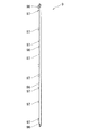
- front cabinet
- display device
- cabinet
- decorative
- Prior art date
- Legal status (The legal status is an assumption and is not a legal conclusion. Google has not performed a legal analysis and makes no representation as to the accuracy of the status listed.)
- Ceased
Links
Images

Classifications
-
- H—ELECTRICITY
- H04—ELECTRIC COMMUNICATION TECHNIQUE
- H04N—PICTORIAL COMMUNICATION, e.g. TELEVISION
- H04N5/00—Details of television systems
- H04N5/64—Constructional details of receivers, e.g. cabinets or dust covers
- H04N5/645—Mounting of picture tube on chassis or in housing
Definitions
- the present invention relates to an image display device such as a television receiver or an image monitor.
- a front cabinet and a back cabinet are joined together to form a thin casing, and a flat display and a pair of left and right speakers are arranged inside the casing.
- the front cabinet is provided with an image display window for displaying an image on the display, and a sound emission hole for emitting sound waves emitted from a pair of left and right speakers is formed at a position below the image display window. Has been.
- an object of the present invention is to provide an image display device in which no burrs or steps are formed at the tips of the decorative ribs protruding from the left and right side walls of the front cabinet.
- a flat display is provided inside a casing formed by joining a front cabinet and a back cabinet to each other, and an image of the display is displayed at the center of the front cabinet.
- An image display window is provided, and decorative ribs that protrude outward from the side walls of the front cabinet are provided on the left and right side walls, respectively.
- the decorative rib has a cross-sectional shape that can be released in the left-right direction along the image display window in the resin molding process, is molded separately from the front cabinet, and is attached to the left and right side walls of the front cabin net It has been.
- the decorative rib since the decorative rib has a cross-sectional shape that can be released in the direction along the image display window in the resin molding step, the decorative rib is formed in the image display window in the step of resin molding.
- the parting line is formed at the end opposite to the protruding direction of the decorative rib, so there is a burr or step at the tip of the decorative rib.
- the burrs or steps are covered by the cabinet or formed at a position retracted from the cabinet surface. None become.
- the decorative rib has an engaging portion to be engaged with the front cabinet, and an ear portion protruding outward from the side wall of the front cabinet, and the ear portion gradually moves forward and backward toward the tip. It has a cross-sectional shape in which the width in the direction is reduced. According to the specific aspect, when the decorative rib is formed of a translucent resin, the thickness of the ear portion gradually decreases toward the tip, so that the transparency gradually changes toward the tip. A gradation effect can be obtained.
- the ear portion of the decorative rib has a front surface region and a rear surface region that gradually narrow each other toward the tip, and has an inner surface region that faces the side wall of the front cabinet,
- the inner surface region is formed in a concave shape that is recessed toward the thick portion sandwiched between the front region and the rear region.
- sink marks due to shrinkage during resin molding occur in the inner surface area, and sink marks are unlikely to occur in the front surface area and the rear surface area, so that the change (distortion) in the cross-sectional shape of the decorative rib is slight. It becomes.
- a plurality of clip pieces that fit into a plurality of protrusion pieces arranged along the left and right side wall portions of the front cabinet protrude from the engaging portion of the decorative rib.
- the decorative rib can be attached to the front cabinet without using a fastening member such as a screw.
- no burr or step is formed at the tip of the decorative rib projecting from the left and right side wall portions of the front cabinet, thereby providing a high design effect on the appearance of the decorative rib. As well as safety.
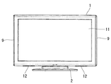
- FIG. 1 is a front view of an image display apparatus according to the present invention.
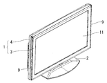
- FIG. 2 is a perspective view of the image display device as viewed from the front side.
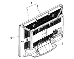
- FIG. 3 is a perspective view of the image display device as seen from the back side.
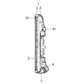
- FIG. 4 is a longitudinal sectional view of the image display device.
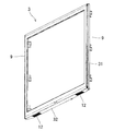
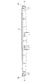
- FIG. 5 is a perspective view of a front cabinet provided with a decorative rib.
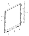
- FIG. 6 is a perspective view of the front cabinet with the decorative ribs disassembled.
- FIG. 7 is a perspective view showing a main part of the front cabinet having decorative ribs.
- FIG. 8 is a perspective view showing a main part of the front cabinet.
- FIG. 9 is a perspective view of the decorative rib.
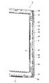
- FIG. 10 is a horizontal cross-sectional view of a front cabinet having decorative ribs.
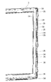
- FIG. 11 is an enlarged horizontal sectional view of the decorative rib.
- the image display device supports a flat housing (1) having an image display window (11) and the housing (1) at a certain height position.
- the case (1) includes a stand (2), and the front cabinet (3) and the back cabinet (4) are joined to each other.
- the front cabinet (3) is provided with a pair of left and right sound emitting holes (12) and (12) exposed below the image display window (11).
- a pair of left and right decorative ribs (9, 9) extending vertically from the upper end to the lower end of the front cabinet (3) are attached to the left and right side walls of the front cabinet (3).
- the decorative rib (9) is a resin molded product made of a translucent synthetic resin (for example, ABS resin, polycarbonate resin, etc.).
- a housing space for various components is formed between the front panel section (31) of the front cabinet (3) and the back panel section (41) of the back cabinet (4).
- a flat display (5) is provided inside the front cabinet (3), and a pair of left and right speaker units (6) and (6) are provided at the bottom of the back cabinet (4).
- the speaker unit (6) is provided with a sound guide bracket (7) for guiding sound waves to the sound emission hole (12).
- the front cabinet (3) includes a frame-shaped front panel portion (31), and side wall portions (33) and (33) protruding rearward from both sides of the front panel portion (31). ), The decorative rib (9) is attached. Further, the sound emission hole (12) is formed in the bottom wall portion (32) protruding rearward from the lower side of the front panel portion (31) of the front cabinet (3).
- the decorative rib (9) has a front engaging portion (92) to be engaged with the front portion of the front panel portion (31) and a side surface to be engaged with the side portion of the front panel portion (31). It has an engaging part (93) and an ear part (91) protruding outward from the side wall of the front cabinet (3), and the ear part (91) is a front surface whose mutual distance gradually narrows toward the tip. It has a region (91a) and a back region (91b), and has an inner surface region (95) facing the side wall (33) of the front panel portion (31), and the inner surface region (95) is a side engaging portion.
- the inner surface region (95) of (93) is formed on the inner side, that is, in a concave shape recessed toward the thick portion sandwiched between the front surface region (91a) and the back surface region (91b) of the ear portion (91).
- a plurality of first clip pieces (96) projecting from the rear edge of the decorative rib (9) toward the front cabinet are provided along the longitudinal direction of the decorative rib (9) as shown in FIG.
- a plurality of second clip pieces (97) projecting from the front edge of the decorative rib (9) toward the front cabinet are projected, and each clip piece (96) (97) has a clip. A hole has been opened.
- the front cabinet (3) is formed with a plurality of first projecting pieces (34) corresponding to the first clip pieces (96) of the decorative rib (9).
- a plurality of second projecting pieces (35) are formed corresponding to the second clip pieces (97) of the decorative rib (9).
- the clip holes of the first clip piece (96) and the second clip piece (97) of the decorative rib (9) are formed with the decorative rib (9) attached to the front cabinet (3) as shown in FIG.
- the decorative ribs (9) are fitted on the side wall (33) of the front cabinet (3) as shown in FIG. 10 by being respectively fitted to the first protruding piece (34) and the second protruding piece (35) of the front cabinet (3). Will be locked.
- the decorative rib (9) is formed of a translucent resin, and as shown in FIG. 11, the ear (91) protrudes outward from the side wall of the front cabinet (3), and its thickness is directed toward the tip. Since the width is gradually reduced, the transparency of the ear portion (91) gradually changes toward the tip, thereby obtaining a gradation effect.
- a mold release method is adopted in which a pair of molds are separated in a direction parallel to the image display window in the cross section (left and right direction in FIG. 11) as shown in FIG.
- the inner surface area (94) of the ear part (91) of the decorative rib (9) is recessed toward the thick part side of the ear part (91)
- the mold release direction is the left-right direction. There is no hindrance.
- the inner surface area (94) of the ear portion (91) of the decorative rib (9) is recessed on the thick portion side of the ear portion (91). Sink marks due to the contraction are concentrated in the inner surface area (94), and scar marks are hardly generated in the front area (91a) and the back area (91b) of the ear (91). Therefore, there is no great deformation in the ear portion (91) of the decorative rib (9) as the resin contracts during resin molding.
Landscapes
- Engineering & Computer Science (AREA)
- Multimedia (AREA)
- Signal Processing (AREA)
- Devices For Indicating Variable Information By Combining Individual Elements (AREA)
Abstract
フロントキャビネットとバックキャビネットを互いに接合してなる筐体の内部に平面型のディスプレイが配備されている画像表示装置において、フロントキャビネットの左右両側壁部に突設された装飾リブの先端にバリや段差が形成されることのない画像表示装置を提供する。 本発明に係る画像表示装置においては、フロントキャビネット3の左右両側壁部にそれぞれ、フロントキャビネット3の側壁から外側へ突出する装飾リブ9が設けられている。該装飾リブ9は、フロントキャビネット3とは別体に成型され、樹脂成型工程にて画像表示窓に沿う方向の離型が可能な断面形状を有している。
Description
本発明は、テレビジョン受像機や画像モニター等の画像表示装置に関するものである。
一般にテレビジョン受像機においては、フロントキャビネットとバックキャビネットを互いに接合して薄型の筐体が構成され、該筐体の内部に、平面型のディスプレイと左右一対のスピーカとが配備されている。そして、フロントキャビネットには、ディスプレイの画像を表示するための画像表示窓が設けられると共に、該画像表示窓の下方位置に、左右一対のスピーカから発せられる音波を放出するための放音孔が開設されている。
この様なテレビジョン受像機においては、その外観に意匠的効果を与えるべく、フロントキャビネットに種々の装飾部品を配置することが行なわれている。
例えば、フロントキャビネットの左右両側壁部にそれぞれ、フロントキャビネットの側壁部から外側へ突出する装飾リブを一体に成型することが考えられる。
しかしながら、装飾リブをフロントキャビネットと一体に成型する場合、樹脂成型工程において一対の金型を画像表示窓に対して垂直な方向(前後方向)に離間させる離型方式を採用することになるが、この場合、装飾リブの先端がパーティングラインとなるため、その位置にバリや段差が形成されて、外観上並びに安全上の問題があった。
そこで本発明の目的は、フロントキャビネットの左右両側壁部に突設された装飾リブの先端にバリや段差が形成されることのない画像表示装置を提供することである。
本発明に係る画像表示装置においては、フロントキャビネットとバックキャビネットを互いに接合してなる筐体の内部に平面型のディスプレイが配備され、フロントキャビネットには、その中央部に前記ディスプレイの画像を表示するための画像表示窓が設けられると共に、その左右両側壁部にそれぞれ、フロントキャビネットの側壁から外側へ突出する装飾リブが設けられている。
前記装飾リブは、樹脂成型工程にて画像表示窓に沿う左右方向の離型が可能な断面形状を有し、フロントキャビネットとは別体に成型されて、フロントキャビンネットの左右両側壁部に取り付けられている。
前記装飾リブは、樹脂成型工程にて画像表示窓に沿う左右方向の離型が可能な断面形状を有し、フロントキャビネットとは別体に成型されて、フロントキャビンネットの左右両側壁部に取り付けられている。
上記画像表示装置によれば、装飾リブが樹脂成型工程にて画像表示窓に沿う方向の離型が可能な断面形状を有しているので、装飾リブを樹脂成型する工程にて画像表示窓に沿う方向に一対の金型を離間させる離型方式を採用することによって、パーティングラインが装飾リブの突出方向とは逆側の端部に形成されるので、装飾リブの先端にバリや段差が形成されることはない。
尚、装飾リブの突出方向とは逆側の端部にバリや段差が形成されたとしても、そのバリや段差はキャビネットによって覆い隠され、若しくはキャビネット表面から後退した位置に形成されるので、問題になることはない。
尚、装飾リブの突出方向とは逆側の端部にバリや段差が形成されたとしても、そのバリや段差はキャビネットによって覆い隠され、若しくはキャビネット表面から後退した位置に形成されるので、問題になることはない。
具体的態様において、前記装飾リブは、フロントキャビネットに係合すべき係合部と、フロントキャビネットの側壁から外側へ突出する耳部とを有し、該耳部は、先端に向かって徐々に前後方向の幅が縮小する断面形状を有している。
該具体的態様によれば、装飾リブを半透明樹脂によって形成した場合、耳部の肉厚が先端に向かって徐々に幅が縮小するので、その透明度が先端に向かって徐々に変化し、これによってグラデーション効果が得られる。
該具体的態様によれば、装飾リブを半透明樹脂によって形成した場合、耳部の肉厚が先端に向かって徐々に幅が縮小するので、その透明度が先端に向かって徐々に変化し、これによってグラデーション効果が得られる。
他の具体的な態様において、前記装飾リブの耳部は、先端に向かって互いの間隔が徐々に狭まる前面領域と背面領域を有すると共に、フロントキャビネットの側壁に対向する内面領域を有し、該内面領域は、前面領域と背面領域によって挟まれた肉厚部側へ凹んだ凹面状に形成されている。
該具体的態様によれば、樹脂成型時の収縮によるひけが内面領域に発生し、前面領域や背面領域にはひけが発生し難いため、装飾リブの断面形状の変化(歪み)が軽微なものとなる。
該具体的態様によれば、樹脂成型時の収縮によるひけが内面領域に発生し、前面領域や背面領域にはひけが発生し難いため、装飾リブの断面形状の変化(歪み)が軽微なものとなる。
更に具体的な態様において、前記装飾リブの係合部には、フロントキャビネットの左右両側壁部に沿って配列された複数の突片に嵌合する複数のクリップ片が突設されている。
該具体的態様によれば、ビス等の締結部材を用いることなく、フロントキャビネットに装飾リブを取り付けることが出来る。
該具体的態様によれば、ビス等の締結部材を用いることなく、フロントキャビネットに装飾リブを取り付けることが出来る。
本発明に係る画像表示装置によれば、フロントキャビネットの左右両側壁部に突設された装飾リブの先端にバリや段差が形成されることはなく、これによって装飾リブの外観に高い意匠的効果が得られると共に、安全性も確保される。
以下、本発明の実施の形態につき、図面に沿って具体的に説明する。
本発明に係る画像表示装置は、図1~図3に示す如く、画像表示窓(11)を有する扁平な筐体(1)と、該筐体(1)を一定の高さ位置に支持するスタンド(2)とを具え、該筐体(1)は、フロントキャビネット(3)とバックキャビネット(4)を互いに接合して構成されている。フロントキャビネット(3)には、画像表示窓(11)の下方に露出する左右一対の放音孔(12)(12)が開設されている。
本発明に係る画像表示装置は、図1~図3に示す如く、画像表示窓(11)を有する扁平な筐体(1)と、該筐体(1)を一定の高さ位置に支持するスタンド(2)とを具え、該筐体(1)は、フロントキャビネット(3)とバックキャビネット(4)を互いに接合して構成されている。フロントキャビネット(3)には、画像表示窓(11)の下方に露出する左右一対の放音孔(12)(12)が開設されている。
フロントキャビネット(3)の左右両側壁部には、フロントキャビネット(3)の上端から下端まで鉛直方向に伸びる左右一対の装飾リブ(9)(9)が取り付けられている。
装飾リブ(9)は、半透明の合成樹脂(例えばABS樹脂、ポリカーボネート樹脂など)を材質とする樹脂成型品である。
装飾リブ(9)は、半透明の合成樹脂(例えばABS樹脂、ポリカーボネート樹脂など)を材質とする樹脂成型品である。
図4に示す如く、フロントキャビネット(3)のフロントパネル部(31)とバックキャビネット(4)のバックパネル部(41)との間には、各種部品の収容空間が形成されている。
そして、フロントキャビネット(3)の内部に平面型のディスプレイ(5)が配備されると共に、バックキャビネット(4)の底部には、左右一対となるスピーカユニット(6)(6)が配備され、各スピーカユニット(6)には、前記放音孔(12)へ音波を導くための導音ブラケット(7)が取り付けられている。
そして、フロントキャビネット(3)の内部に平面型のディスプレイ(5)が配備されると共に、バックキャビネット(4)の底部には、左右一対となるスピーカユニット(6)(6)が配備され、各スピーカユニット(6)には、前記放音孔(12)へ音波を導くための導音ブラケット(7)が取り付けられている。
図5及び図6に示す如く、フロントキャビネット(3)は、枠状のフロントパネル部(31)を具え、該フロントパネル部(31)の両側辺から後方へ突出する側壁部(33)(33)にそれぞれ前記の装飾リブ(9)が取り付けられている。
又、フロントキャビネット(3)のフロントパネル部(31)の下辺から後方へ突出する底壁部(32)に前記の放音孔(12)が開設されている。
又、フロントキャビネット(3)のフロントパネル部(31)の下辺から後方へ突出する底壁部(32)に前記の放音孔(12)が開設されている。
装飾リブ(9)は、図11に示す如くフロントパネル部(31)の前面部分に係合すべき前面係合部(92)と、フロントパネル部(31)の側面部分に係合すべき側面係合部(93)と、フロントキャビネット(3)の側壁から外側へ突出する耳部(91)とを有し、該耳部(91)は、先端に向かって互いの間隔が徐々に狭まる前面領域(91a)と背面領域(91b)を有すると共に、フロントパネル部(31)の側壁部(33)に対向する内面領域(95)を有し、該内面領域(95)は、側面係合部(93)の内面領域(95)よりも内側、即ち耳部(91)の前面領域(91a)と背面領域(91b)によって挟まれた肉厚部側へ凹んだ凹面状に形成されている。
装飾リブ(9)には、図9に示す如くその長手方向に沿って、装飾リブ(9)の背面側の端縁からフロントキャビネット側へ突出する複数の第1クリップ片(96)が突設されると共に、装飾リブ(9)の前面側の端縁からフロントキャビネット側へ突出する複数の第2クリップ片(97)が突設されており、各クリップ片(96)(97)にはクリップ孔が開設されている。
一方、フロントキャビネット(3)には、図8に示す如く、前記装飾リブ(9)の第1クリップ片(96)に対応して複数の第1突片(34)が形成されると共に、前記装飾リブ(9)の第2クリップ片(97)に対応して複数の第2突片(35)が形成されている。
そして、図7に示す如くフロントキャビネット(3)に装飾リブ(9)が取り付けられた状態で、装飾リブ(9)の第1クリップ片(96)及び第2クリップ片(97)のクリップ孔がフロントキャビネット(3)の第1突片(34)及び第2突片(35)にそれぞれ嵌合して、図10の如くフロントキャビネット(3)の側壁部(33)に装飾リブ(9)が係止されることになる。
上述の如く装飾リブ(9)は半透明樹脂によって形成されており、然も図11の如く耳部(91)がフロントキャビネット(3)の側壁から外側へ突出し、その肉厚が先端に向かって徐々に幅が縮小しているので、耳部(91)の透明度が先端に向かって徐々に変化し、これによってグラデーション効果が得られる。
装飾リブ(9)の樹脂成型工程においては、図11に示す如く断面において画像表示窓と平行な方向(図11の左右方向)に一対の金型を離間させる離型方式が採用される。
ここで、装飾リブ(9)の耳部(91)の内面領域(94)は耳部(91)の肉厚部側に凹んでいるが、離型方向が左右方向であるので、離型に支障はない。
ここで、装飾リブ(9)の耳部(91)の内面領域(94)は耳部(91)の肉厚部側に凹んでいるが、離型方向が左右方向であるので、離型に支障はない。
これによって、離型時のパーティングラインが装飾リブ(9)の係合部(92)(93)側の端部に形成されることとなる。従って、装飾リブ(9)の先端Pにバリや段差が形成されることはない。
尚、装飾リブ(9)の係合部(92)(93)側の端部にバリや段差が形成されたとしても、そのバリや段差はフロントキャビネット(3)によって覆い隠され、若しくはキャビネット表面から後退した位置に形成されるので、問題になることはない。
尚、装飾リブ(9)の係合部(92)(93)側の端部にバリや段差が形成されたとしても、そのバリや段差はフロントキャビネット(3)によって覆い隠され、若しくはキャビネット表面から後退した位置に形成されるので、問題になることはない。
又、装飾リブ(9)の樹脂成型工程においては、装飾リブ(9)の耳部(91)の内面領域(94)が耳部(91)の肉厚部側に凹んでいるので、樹脂の収縮に伴うヒケは、該内面領域(94)に集中的に発生し、耳部(91)の前面領域(91a)や背面領域(91b)には殆どヒケが発生することはない。
従って、樹脂成型時の樹脂の収縮に伴って装飾リブ(9)の耳部(91)に大きな変形を生じることはない。
従って、樹脂成型時の樹脂の収縮に伴って装飾リブ(9)の耳部(91)に大きな変形を生じることはない。
(1) 筐体
(11) 画像表示窓
(2) スタンド
(3) フロントキャビネット
(31) フロントパネル部
(33) 側壁部
(4) バックキャビネット
(9) 装飾リブ
(91) 耳部
(91a) 前面領域
(91b) 背面領域
(92) 前面係合部
(93) 側面係合部
(94) 内面領域
(11) 画像表示窓
(2) スタンド
(3) フロントキャビネット
(31) フロントパネル部
(33) 側壁部
(4) バックキャビネット
(9) 装飾リブ
(91) 耳部
(91a) 前面領域
(91b) 背面領域
(92) 前面係合部
(93) 側面係合部
(94) 内面領域
Claims (4)
- フロントキャビネットとバックキャビネットを互いに接合してなる筐体の内部に平面型のディスプレイが配備され、フロントキャビネットには、その中央部に前記ディスプレイの画像を表示するための画像表示窓が設けられると共に、その左右両側壁部にそれぞれ、フロントキャビネットの側壁から外側へ突出する装飾リブが設けられている画像表示装置において、前記装飾リブは、樹脂成型工程にて画像表示窓に沿う方向の離型が可能な断面形状を有し、フロントキャビネットとは別体に成型されて、フロントキャビンネットの左右両側壁部に取り付けられていることを特徴とする画像表示装置。
- 前記装飾リブは、フロントキャビネットに係合すべき係合部と、フロントキャビネットの側壁から外側へ突出する耳部とを有し、該耳部は、先端に向かって徐々に前後方向の幅が縮小する断面形状を有している請求項1に記載の画像表示装置。
- 前記装飾リブの耳部は、先端に向かって互いの間隔が徐々に狭まる前面領域と背面領域を有すると共に、フロントキャビネットの側壁に対向する内面領域を有し、該内面領域は、前面領域と背面領域によって挟まれた肉厚部側へ凹んだ凹面状に形成されている請求項2に記載の画像表示装置。
- 前記装飾リブの係合部には、フロントキャビネットの左右両側壁部に沿って配列された複数の突片に嵌合する複数のクリップ片が突設されている請求項2又は請求項3に記載の画像表示装置。
Applications Claiming Priority (2)
| Application Number | Priority Date | Filing Date | Title |
|---|---|---|---|
| JP2009-224479 | 2009-09-29 | ||
| JP2009224479A JP2011075638A (ja) | 2009-09-29 | 2009-09-29 | 画像表示装置 |
Publications (1)
| Publication Number | Publication Date |
|---|---|
| WO2011040322A1 true WO2011040322A1 (ja) | 2011-04-07 |
Family
ID=43826143
Family Applications (1)
| Application Number | Title | Priority Date | Filing Date |
|---|---|---|---|
| PCT/JP2010/066527 Ceased WO2011040322A1 (ja) | 2009-09-29 | 2010-09-24 | 画像表示装置 |
Country Status (2)
| Country | Link |
|---|---|
| JP (1) | JP2011075638A (ja) |
| WO (1) | WO2011040322A1 (ja) |
Citations (4)
| Publication number | Priority date | Publication date | Assignee | Title |
|---|---|---|---|---|
| JPH0361772U (ja) * | 1989-10-19 | 1991-06-17 | ||
| JPH06311459A (ja) * | 1993-04-27 | 1994-11-04 | Hitachi Ltd | キャビネットのバックカバー取付け構造 |
| JP2004058413A (ja) * | 2002-07-26 | 2004-02-26 | Ricoh Co Ltd | 樹脂成形品 |
| JP2009105517A (ja) * | 2007-10-22 | 2009-05-14 | Hitachi Ltd | 電子機器の筐体構造 |
-
2009
- 2009-09-29 JP JP2009224479A patent/JP2011075638A/ja active Pending
-
2010
- 2010-09-24 WO PCT/JP2010/066527 patent/WO2011040322A1/ja not_active Ceased
Patent Citations (4)
| Publication number | Priority date | Publication date | Assignee | Title |
|---|---|---|---|---|
| JPH0361772U (ja) * | 1989-10-19 | 1991-06-17 | ||
| JPH06311459A (ja) * | 1993-04-27 | 1994-11-04 | Hitachi Ltd | キャビネットのバックカバー取付け構造 |
| JP2004058413A (ja) * | 2002-07-26 | 2004-02-26 | Ricoh Co Ltd | 樹脂成形品 |
| JP2009105517A (ja) * | 2007-10-22 | 2009-05-14 | Hitachi Ltd | 電子機器の筐体構造 |
Also Published As
| Publication number | Publication date |
|---|---|
| JP2011075638A (ja) | 2011-04-14 |
Similar Documents
| Publication | Publication Date | Title |
|---|---|---|
| CN101877951B (zh) | 用于电子装置的外壳、包括该外壳的装置及制造该外壳的方法 | |
| JP5428784B2 (ja) | 車両内装品の組付構造 | |
| JP6076170B2 (ja) | 鍵盤楽器の鍵 | |
| JP5166613B1 (ja) | 表示装置、及びテレビジョン受信機 | |
| JP7046672B2 (ja) | ピアノの長尺部品の取付け構造 | |
| JP5250452B2 (ja) | 撮像装置の筐体 | |
| CN104160795A (zh) | 线夹安装结构及显示装置 | |
| USD541268S1 (en) | Rack-mounted enclosure | |
| JP6183653B2 (ja) | インストルメントパネルの加飾部品の取り付け構造 | |
| JP2011075638A (ja) | 画像表示装置 | |
| JP4301324B2 (ja) | テレビジョン受像機 | |
| KR101590642B1 (ko) | 디스플레이 장치 | |
| JP6824207B2 (ja) | パネル装置 | |
| JP5009863B2 (ja) | センサープロテクター | |
| JP6383220B2 (ja) | プライスホルダの製造方法 | |
| JP2016029619A (ja) | エクステンションの製造方法、エクステンション及び車両用灯具 | |
| TWI498069B (zh) | 電子裝置機殼及其製造方法 | |
| CN207921886U (zh) | 一种新型面板导光结构 | |
| JP6233962B2 (ja) | 収納装置 | |
| JP4595970B2 (ja) | テレビジョン装置 | |
| JP5743670B2 (ja) | 表示装置およびその筐体取付構造 | |
| JP5800880B2 (ja) | 表示装置 | |
| JP2015217847A (ja) | 車両用樹脂部品及び車両用樹脂部品の製造方法 | |
| JP2016049711A (ja) | バンパ製造装置および樹脂製品製造装置 | |
| JP2007184472A (ja) | 電気機器キャビネット |
Legal Events
| Date | Code | Title | Description |
|---|---|---|---|
| 121 | Ep: the epo has been informed by wipo that ep was designated in this application |
Ref document number: 10820440 Country of ref document: EP Kind code of ref document: A1 |
|
| NENP | Non-entry into the national phase |
Ref country code: DE |
|
| 122 | Ep: pct application non-entry in european phase |
Ref document number: 10820440 Country of ref document: EP Kind code of ref document: A1 |