WO2011040127A1 - コイルの製造装置及び製造方法 - Google Patents
コイルの製造装置及び製造方法 Download PDFInfo
- Publication number
- WO2011040127A1 WO2011040127A1 PCT/JP2010/063613 JP2010063613W WO2011040127A1 WO 2011040127 A1 WO2011040127 A1 WO 2011040127A1 JP 2010063613 W JP2010063613 W JP 2010063613W WO 2011040127 A1 WO2011040127 A1 WO 2011040127A1
- Authority
- WO
- WIPO (PCT)
- Prior art keywords
- pipe
- coil
- shaped
- straight
- straight pipe
- Prior art date
- Legal status (The legal status is an assumption and is not a legal conclusion. Google has not performed a legal analysis and makes no representation as to the accuracy of the status listed.)
- Ceased
Links
Images






Classifications
-
- B—PERFORMING OPERATIONS; TRANSPORTING
- B23—MACHINE TOOLS; METAL-WORKING NOT OTHERWISE PROVIDED FOR
- B23K—SOLDERING OR UNSOLDERING; WELDING; CLADDING OR PLATING BY SOLDERING OR WELDING; CUTTING BY APPLYING HEAT LOCALLY, e.g. FLAME CUTTING; WORKING BY LASER BEAM
- B23K26/00—Working by laser beam, e.g. welding, cutting or boring
- B23K26/20—Bonding
- B23K26/21—Bonding by welding
- B23K26/24—Seam welding
- B23K26/30—Seam welding of three-dimensional [3D] seams
-
- B—PERFORMING OPERATIONS; TRANSPORTING
- B23—MACHINE TOOLS; METAL-WORKING NOT OTHERWISE PROVIDED FOR
- B23K—SOLDERING OR UNSOLDERING; WELDING; CLADDING OR PLATING BY SOLDERING OR WELDING; CUTTING BY APPLYING HEAT LOCALLY, e.g. FLAME CUTTING; WORKING BY LASER BEAM
- B23K26/00—Working by laser beam, e.g. welding, cutting or boring
- B23K26/02—Positioning or observing the workpiece, e.g. with respect to the point of impact; Aligning, aiming or focusing the laser beam
- B23K26/03—Observing, e.g. monitoring, the workpiece
- B23K26/032—Observing, e.g. monitoring, the workpiece using optical means
-
- B—PERFORMING OPERATIONS; TRANSPORTING
- B23—MACHINE TOOLS; METAL-WORKING NOT OTHERWISE PROVIDED FOR
- B23K—SOLDERING OR UNSOLDERING; WELDING; CLADDING OR PLATING BY SOLDERING OR WELDING; CUTTING BY APPLYING HEAT LOCALLY, e.g. FLAME CUTTING; WORKING BY LASER BEAM
- B23K26/00—Working by laser beam, e.g. welding, cutting or boring
- B23K26/08—Devices involving relative movement between laser beam and workpiece
- B23K26/0869—Devices involving movement of the laser head in at least one axial direction
- B23K26/0876—Devices involving movement of the laser head in at least one axial direction in at least two axial directions
-
- B—PERFORMING OPERATIONS; TRANSPORTING
- B23—MACHINE TOOLS; METAL-WORKING NOT OTHERWISE PROVIDED FOR
- B23K—SOLDERING OR UNSOLDERING; WELDING; CLADDING OR PLATING BY SOLDERING OR WELDING; CUTTING BY APPLYING HEAT LOCALLY, e.g. FLAME CUTTING; WORKING BY LASER BEAM
- B23K37/00—Auxiliary devices or processes, not specially adapted for a procedure covered by only one of the other main groups of this subclass
- B23K37/04—Auxiliary devices or processes, not specially adapted for a procedure covered by only one of the other main groups of this subclass for holding or positioning work
- B23K37/0426—Fixtures for other work
- B23K37/0435—Clamps
-
- B—PERFORMING OPERATIONS; TRANSPORTING
- B23—MACHINE TOOLS; METAL-WORKING NOT OTHERWISE PROVIDED FOR
- B23K—SOLDERING OR UNSOLDERING; WELDING; CLADDING OR PLATING BY SOLDERING OR WELDING; CUTTING BY APPLYING HEAT LOCALLY, e.g. FLAME CUTTING; WORKING BY LASER BEAM
- B23K2101/00—Articles made by soldering, welding or cutting
- B23K2101/04—Tubular or hollow articles
-
- B—PERFORMING OPERATIONS; TRANSPORTING
- B23—MACHINE TOOLS; METAL-WORKING NOT OTHERWISE PROVIDED FOR
- B23K—SOLDERING OR UNSOLDERING; WELDING; CLADDING OR PLATING BY SOLDERING OR WELDING; CUTTING BY APPLYING HEAT LOCALLY, e.g. FLAME CUTTING; WORKING BY LASER BEAM
- B23K2101/00—Articles made by soldering, welding or cutting
- B23K2101/04—Tubular or hollow articles
- B23K2101/06—Tubes
Definitions
- the present invention uses a device for manufacturing a serpentine tube (hereinafter referred to as a coil), which is used in a boiler or the like, having U-shaped tubes connected to both ends of a straight tube with high accuracy and high efficiency, and this manufacturing device. It relates to a manufacturing method.
- a serpentine tube hereinafter referred to as a coil
- a serpentine tube such as a coil has been manufactured by bending a long tube in which straight tubes are welded in series.
- the thickness of the tube exceeds 4 mm and the welded part between the straight pipes is bent, damage such as wrinkles occurs in the bent part.
- the inner surface of the coil (especially the inner surface of the welded part between the straight pipe and the U-shaped pipe) is infinitely flat in order to reduce pipe resistance, stress concentration, etc. It is desirable to be.
- the problem to be solved by the present invention is that when a coil is manufactured by connecting U-shaped tubes to both ends of a straight tube by TIG welding, it is necessary to form a groove shape in the U shape. Further, the productivity is very poor, and there is a possibility that the extra height of the inner surface may be increased.
- the coil manufacturing apparatus of the present invention comprises: To enable highly accurate and highly efficient manufacturing, An apparatus for manufacturing a coil by welding U-shaped pipes to both ends of a plurality of straight pipes, A collection tube having a focal length that is at least twice the diameter of the pipe to be welded with respect to the groove positions of the straight pipe positioned and held by the work setting jig and the U-shaped pipe temporarily attached to both ends of the straight pipe.
- a laser welding head that performs welding by irradiating laser light using an optical lens is provided.
- laser welding is performed by irradiating a condensing lens having a focal length that is twice or more the diameter of the pipe to be welded in a state where the work set jig is positioned and held. welding to adjacent portions of adjacent tubes can be easily performed.
- the laser welding head when the laser welding head is provided with a camera for recognizing the groove positions of the straight pipe and the U-shaped pipe, the irradiation position of the laser beam can be accurately recognized. Stable welding can be performed without coming off.
- a preheating apparatus for preheating the groove positions of the straight pipe and the U-shaped pipe.
- this preheating device is a high frequency preheating device having an oval or elliptical high frequency coil whose cross section in a direction perpendicular to the longitudinal direction of the straight pipe is 5 to 50 mm larger than the oval circumscribing the U-shaped tube, Efficient preheating can be performed by surrounding the U-shaped tube with a high-frequency coil.
- thermometer that measures the temperature of the straight pipe and the U-shaped pipe is provided in the preheating device, it is possible to accurately grasp whether or not the temperature at the welding position at the end of preheating is a predetermined temperature. desirable.
- the coil manufacturing method of the present invention is a method of manufacturing a coil by welding U-shaped pipes to both ends of a plurality of straight pipes using the above-described apparatus of the present invention, Inductively heat the straight pipe and the U-shaped tube to a predetermined temperature or higher by a high-frequency coil installed so as to surround the U-shaped pipe temporarily attached to both ends of the straight pipe, After confirming that the temperature of the induction-heated straight pipe and the U-shaped pipe reaches a predetermined temperature, the pipe diameter of the welded pipe is 2 with respect to the groove position between the confirmed straight pipe and the U-shaped pipe.
- the main feature is that welding is performed by irradiating a laser beam using a condensing lens having a focal length more than double.
- the coil can be manufactured with high accuracy and high efficiency without using a filler wire.
- a condenser lens having a focal length more than twice the diameter of the pipe to be welded is intended to manufacture a coil in which U-tubes are connected to both ends of a straight pipe with high accuracy and high efficiency. This was realized by irradiating laser beam to the laser welding.
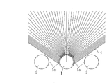
- the coil has a straight pipe at a position adjacent to the adjacent straight pipe 1 as shown in FIG. It is difficult to irradiate the laser beam 4 perpendicularly to the adjacent portions 1a. In laser welding, the laser beam is focused on a small spot and the energy density is increased for welding. Therefore, it is necessary to accurately recognize the welding position.
- welding between the straight pipe 1 and the U-shaped pipe 2 temporarily attached to both ends of the straight pipe 1 has a focal length that is twice or more the pipe diameter d of the welded pipes 1 and 2. This is performed by irradiating laser light using a condenser lens.
- the adjacent portion 1a of the adjacent straight tube 1 is also irradiated with the laser beam vertically. be able to.
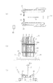
- the laser welding head 11 includes a straight tube 1 and a U-shaped tube via a collimating lens 14 and a condenser lens 15 that convert laser light 13 emitted from a laser oscillator 12 into parallel light. 2, the straight pipe 1 and the U-shaped pipe 2 are laser-welded by irradiating the groove position w of the welded part 2.
- beam splitters 16 a and 16 b that transmit the laser light 13 but reflect visible light are arranged on the optical axis of the laser light 13 between the collimating lens 14 and the condenser lens 15.
- the groove position w of the tube 1 and the U-tube 2 is projected and imaged by the camera 17.
- the camera 17 and the beam splitter 16a are attached and fixed to the outer surface of the laser welding head 11.
- the irradiation position of the laser beam 13 condensed to about 0.5 mm can be accurately recognized. Therefore, stable laser welding can be performed without any problem.
- a non-contact thermometer 18 that measures the temperature of the groove position w of the straight pipe 1 and the U-shaped pipe 2 before laser welding is provided.
- the non-contact thermometer 18 it can be confirmed whether the temperature of the groove position w of the straight pipe 1 and the U-shaped pipe 2 to be laser-welded has reached a specified temperature.
- 19 is a processing device for an image taken by the camera 17, 20 is inputted with an image of the image processing device 19 and a temperature measured by the non-contact thermometer 18, and controls the laser oscillator 12.
- a laser controller 21 is a monitor that captures an image of the image processing device 19.
- laser welding performs rapid heating compared to TIG welding, and thus easily changes the original properties of the material to be welded. Therefore, in order to prevent this change, it is desirable to preheat the material to be welded prior to welding. This preheating can alleviate the adverse effects of rapid heating and cooling, and is effective in preventing weld cracking and securing an appropriate structure.
- a preheating device 22 for preheating the groove position w of the straight pipe 1 and the U-shaped pipe 2 as shown in FIG. 5 is provided.
- a high frequency preheating device having an oval high frequency coil 22a whose cross section in the direction orthogonal to the longitudinal direction of the straight tube 1 is 5 to 50 mm larger than an ellipse circumscribing the U-shaped tube 2 is shown. ing.
- the distance of the high-frequency coil 22a larger than the ellipse circumscribing the U-shaped tube 2 is less than 5 mm, the high-frequency coil 22a is likely to come into contact with the U-shaped tube 2 during setting for preheating. On the other hand, if it exceeds 50 mm, the high-frequency coil 22a and the welded portion are too far apart and it is difficult to preheat to a predetermined temperature. Therefore, the distance is preferably 5 to 50 mm.
- the high-frequency coil 22a surrounds the U-shaped tube 2, so that efficient preheating can be performed.
- a radiation thermometer 23 is provided in the preheating device 22 to measure the temperature of the straight pipe 1 and the U-shaped pipe 2, the temperature monitored by the radiation thermometer 23 is fed back.
- the temperature at the welding position can be accurately controlled.
- the preheating device 22 is positioned at a retracted position on the extension line where the straight pipe 1 and the U-shaped pipe 2 positioned and held by the work setting jig 24 are arranged. It is desirable to preheat by moving upward after moving to the position.
- the laser welding device 31 to which the laser welding head 11 is movably attached (rotated) is positioned and held by the work setting jig 24 as shown in FIG.
- Two units are arranged on both sides of the straight tube 1 and the U-shaped tube 2 in a direction orthogonal to the direction in which the character tubes 2 are arranged, and the straight tube 1 and the U-shaped tube 2 are sandwiched therebetween.
- These two laser welding apparatuses 31 are provided so as to be movable in the direction in which the straight pipe 1 and the U-shaped pipe 2 are arranged.
- the two laser welding apparatuses 31 arranged in this way are moved in the direction in which the straight pipe 1 and the U-shaped pipe 2 are arranged, and the straight pipe 1 and the U from both sides of the straight pipe 1 using the laser welding head 11.
- the coil 3 can be manufactured in a short time and with high efficiency.
- the work setting jig 24 for positioning and holding the straight pipe 1 and the U-shaped pipe 2 is arranged so that the positions of the U-shaped pipes 2 temporarily attached to both ends of the straight pipe 1 can be switched as shown in FIG. As indicated by the arrows in FIG. 4), it is desirable that the fulcrum 24a is reversible around the fulcrum 24a.
- reference numeral 25 in FIG. 7 denotes a control panel.
- the preheating device 22 When preheating is required, the preheating device 22 is moved, the preheating device 22 is moved up, the weld is surrounded by the high frequency coil 22a, and preheating (induction heating) is performed according to the program. 4) When preheating according to the program is finished, the preheating device 22 is lowered and moved to the retracted position.
- each laser welding head 11 is retracted to a position where the temperature of each welded part can be measured by the non-contact thermometer 18 and the temperature of each welded part is measured.
- the respective laser welding heads 11 After confirming that the temperature of the welded portion is a predetermined temperature, the respective laser welding heads 11 are moved to the accurate welding positions, and laser welding is performed according to pre-programmed welding conditions.
- the preheating device 22 is moved up and down during the preheating, but the work setting jig 24 holding the straight tube 1 temporarily attached with the U-shaped tube 2 at both ends may be moved up and down.
- the welding work is not limited to being performed automatically, and each process may be performed while the welder is checking.
- the present invention is not limited to the manufacture of the coil 3 in which both ends of a straight pipe are connected by U-shaped pipes, which are used in a boiler or the like as long as adjacent pipes are welded.
Landscapes
- Physics & Mathematics (AREA)
- Optics & Photonics (AREA)
- Engineering & Computer Science (AREA)
- Mechanical Engineering (AREA)
- Plasma & Fusion (AREA)
- Laser Beam Processing (AREA)
Abstract
Description
高精度で、かつ高能率での製造を可能にするために、
複数の直管の両端にU字管を溶接してコイルを製造する装置であって、
ワークセット治具に位置決め保持された直管と、この直管の両端に仮付けされたU字管の開先位置に対して、被溶接管の管径の2倍以上の焦点距離を有する集光レンズを用いてレーザ光を照射することにより溶接を行うレーザ溶接ヘッドを備えたことを最も主要な特徴としている。
直管との両端に仮付けされたU字管を囲むように設置した高周波コイルにより、直管及びU字管を所定温度以上になるまで誘導加熱し、
この誘導加熱した直管とU字管の温度が所定温度になるのを確認した後、この確認した直管とU字管の間の開先位置に対して、被溶接管の管径の2倍以上の焦点距離を有する集光レンズを用いてレーザ光を照射して溶接することを主要な特徴としている。
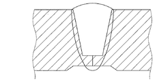
レーザ溶接を採用すれば、厚みが8mmの、直管の両端にU字管を連結したコイルであっても、図1に示すようなI型の簡単な開先wで、図2に示すような内面のビード高さの低い溶接を、70cm/minもの高速で行うことができる。
2) ワークセット治具24にセットされた、両端にU字管2を仮付した直管1のおおよその位置を制御盤25に入力する。
4) プログラムに従った予熱が終了すると、予熱装置22を下降し、退避位置まで移動させる。
9) 直管1の一方端部におけるU字管2との接合が完了した後、ワークセット治具24を反転し、直管1の他方端部におけるU字管2との接合を同様に行う。
1a 隣接する部分
2 U字管
3 コイル
11 レーザ溶接ヘッド
13 レーザ光
15 集光レンズ
16a、16b ビームスプリッター
17 カメラ
22 予熱装置
22a 高周波コイル
23 放射温度計
24 ワークセット治具
24a 支点
31 レーザ溶接装置
Claims (15)
- 複数の直管の両端にU字管を溶接してコイルを製造する装置であって、
ワークセット治具に位置決め保持された直管と、この直管の両端に仮付けされたU字管の開先位置に対して、被溶接管の管径の2倍以上の焦点距離を有する集光レンズを用いてレーザ光を照射することにより溶接を行うレーザ溶接ヘッドを備えたことを特徴とするコイルの製造装置。 - 前記レーザ溶接ヘッドに、直管とU字管の前記開先位置を認識するカメラを備えさせたことを特徴とする請求項1に記載のコイルの製造装置。
- 前記レーザ溶接ヘッドは、前記溶接する直管とU字管が並べられた方向と直交する方向の前記直管の両側に2台、前記溶接する直管とU字管が並べられた方向にそれぞれが移動自在に設けられていることを特徴とする請求項1又は2に記載のコイルの製造装置。
- 直管とU字管の前記開先位置を予熱処理する予熱装置を設けたことを特徴とする請求項1又は2に記載のコイルの製造装置。
- 直管とU字管の前記開先位置を予熱処理する予熱装置を設けたことを特徴とする請求項3に記載のコイルの製造装置。
- 前記予熱装置は、直管の長手方向と直交する方向の断面が、U字管と外接する長円より5~50mm大きい、長円形又は楕円形の高周波コイルを有する高周波予熱装置であることを特徴とする請求項4に記載のコイルの製造装置。
- 前記予熱装置は、直管の長手方向と直交する方向の断面が、U字管と外接する長円より5~50mm大きい、長円形又は楕円形の高周波コイルを有する高周波予熱装置であることを特徴とする請求項5に記載のコイルの製造装置。
- 前記予熱装置には、直管及びU字管の温度を計測する非接触温度計が設けられていることを特徴とする請求項4に記載のコイルの製造装置。
- 前記予熱装置には、直管及びU字管の温度を計測する非接触温度計が設けられていることを特徴とする請求項5~7の何れかに記載のコイルの製造装置。
- 前記ワークセット治具が、直管の両端に仮付けされたU字管の位置の入れ替えが可能なように反転可能に構成されていることを特徴とする請求項1又は2に記載のコイルの製造装置。
- 前記ワークセット治具が、直管の両端に仮付けされたU字管の位置の入れ替えが可能なように反転可能に構成されていることを特徴とする請求項3に記載のコイルの製造装置。
- 前記ワークセット治具が、直管の両端に仮付けされたU字管の位置の入れ替えが可能なように反転可能に構成されていることを特徴とする請求項4に記載のコイルの製造装置。
- 前記ワークセット治具が、直管の両端に仮付けされたU字管の位置の入れ替えが可能なように反転可能に構成されていることを特徴とする請求項5~8の何れかに記載のコイルの製造装置。
- 前記ワークセット治具が、直管の両端に仮付けされたU字管の位置の入れ替えが可能なように反転可能に構成されていることを特徴とする請求項9に記載のコイルの製造装置。
- 複数の直管の両端にU字管を溶接してコイルを製造する方法であって、
直管との両端に仮付けされたU字管を囲むように設置した高周波コイルにより、直管及びU字管を所定温度以上になるまで誘導加熱し、
この誘導加熱した直管とU字管の温度が所定温度になるのを確認した後、この確認した直管とU字管の間の開先位置に対して、被溶接管の管径の2倍以上の焦点距離を有する集光レンズを用いてレーザ光を照射して溶接することを特徴とするコイルの製造方法。
Priority Applications (1)
| Application Number | Priority Date | Filing Date | Title |
|---|---|---|---|
| US13/499,877 US20120217228A1 (en) | 2009-10-02 | 2010-08-11 | Coil manufacturing device and method |
Applications Claiming Priority (2)
| Application Number | Priority Date | Filing Date | Title |
|---|---|---|---|
| JP2009230882A JP5523045B2 (ja) | 2009-10-02 | 2009-10-02 | コイルの製造装置及び製造方法 |
| JP2009-230882 | 2009-10-02 |
Publications (1)
| Publication Number | Publication Date |
|---|---|
| WO2011040127A1 true WO2011040127A1 (ja) | 2011-04-07 |
Family
ID=43825961
Family Applications (1)
| Application Number | Title | Priority Date | Filing Date |
|---|---|---|---|
| PCT/JP2010/063613 Ceased WO2011040127A1 (ja) | 2009-10-02 | 2010-08-11 | コイルの製造装置及び製造方法 |
Country Status (3)
| Country | Link |
|---|---|
| US (1) | US20120217228A1 (ja) |
| JP (1) | JP5523045B2 (ja) |
| WO (1) | WO2011040127A1 (ja) |
Cited By (2)
| Publication number | Priority date | Publication date | Assignee | Title |
|---|---|---|---|---|
| CN104785964A (zh) * | 2015-04-20 | 2015-07-22 | 骏马石油装备制造有限公司 | 一种辐射段盘管焊接工作站 |
| CN108817820A (zh) * | 2018-09-07 | 2018-11-16 | 卢运丰 | 一种中央空调集气管定位焊接用辅助工具 |
Families Citing this family (3)
| Publication number | Priority date | Publication date | Assignee | Title |
|---|---|---|---|---|
| JP6010349B2 (ja) * | 2011-06-09 | 2016-10-19 | 株式会社ニデック | 染色方法及び染色装置 |
| JP6425596B2 (ja) * | 2015-03-26 | 2018-11-21 | 日立造船株式会社 | 管のレーザ溶接方法及びその溶接方法を用いて製造されるコイル |
| CN107263012B (zh) * | 2017-06-22 | 2023-09-22 | 洛阳鹏起实业有限公司 | 一种管件焊接夹具 |
Citations (11)
| Publication number | Priority date | Publication date | Assignee | Title |
|---|---|---|---|---|
| JPS6086778U (ja) * | 1983-11-16 | 1985-06-14 | 三菱重工業株式会社 | スパイラルフイン付鋼管 |
| JPH0270379A (ja) * | 1988-09-05 | 1990-03-09 | Sumitomo Metal Ind Ltd | 複合熱源による製管溶接方法 |
| JPH02268991A (ja) * | 1989-04-11 | 1990-11-02 | Brother Ind Ltd | 亜鉛メッキ鋼板のレーザ溶接方法 |
| JPH06269943A (ja) * | 1993-03-19 | 1994-09-27 | Hisaka Works Ltd | プレート縁継手の開先中心認識方法 |
| JPH10180473A (ja) * | 1996-12-25 | 1998-07-07 | Honda Motor Co Ltd | レーザ加工装置 |
| JP2001041669A (ja) * | 1999-07-30 | 2001-02-16 | Toyo Radiator Co Ltd | 熱交換器の薄肉チューブの溶接方法および溶接構造 |
| JP2005334904A (ja) * | 2004-05-25 | 2005-12-08 | Hitachi Ltd | 自動倣い溶接制御方法及び装置 |
| JP2006142383A (ja) * | 2004-11-17 | 2006-06-08 | Trumpf Laser Gmbh & Co Kg | レーザ溶接装置 |
| JP2007290119A (ja) * | 2007-04-16 | 2007-11-08 | Mitsubishi Electric Engineering Co Ltd | ワーク加工装置及びそのワーク反転装置 |
| JP2008036639A (ja) * | 2006-08-01 | 2008-02-21 | Sumitomo Electric Ind Ltd | レーザ加工方法およびレーザ加工装置 |
| JP2009158901A (ja) * | 2007-12-28 | 2009-07-16 | Tsuji Sogo Denki:Kk | レーザー印字装置 |
Family Cites Families (26)
| Publication number | Priority date | Publication date | Assignee | Title |
|---|---|---|---|---|
| US3555239A (en) * | 1966-11-16 | 1971-01-12 | William J Kerth | Welding machine with digital pulse control |
| US4224499A (en) * | 1978-10-20 | 1980-09-23 | General Electric Company | Laser welding aluminum to copper |
| JPS58119481A (ja) * | 1982-01-08 | 1983-07-15 | Kawasaki Steel Corp | レ−ザ溶接方法 |
| IT1190581B (it) * | 1986-05-29 | 1988-02-16 | Fiat Auto Spa | Procedimento per saldare di testa con l impiego di un fascio laser due pezzi di materiali metallici dissimili in particolare pezzi di acciaio a medio od elevato tenore di carbonic |
| DE3632952A1 (de) * | 1986-09-27 | 1988-04-07 | Hoesch Ag | Verfahren und vorrichtung zur kontinuierlichen herstellung rohrfoermiger koerper mittels laser-laengsnahtschweissung |
| US4737612A (en) * | 1987-02-04 | 1988-04-12 | Westinghouse Electric Corp. | Method of welding |
| US4935029A (en) * | 1987-06-22 | 1990-06-19 | Matsutani Seisakusho Co., Ltd. | Surgical needle |
| US4918284A (en) * | 1988-10-14 | 1990-04-17 | Teradyne Laser Systems, Inc. | Calibrating laser trimming apparatus |
| US5168141A (en) * | 1991-06-14 | 1992-12-01 | General Electric Company | Vision guided laser welding |
| JPH0557467A (ja) * | 1991-09-05 | 1993-03-09 | Toyota Motor Corp | 異板厚素材のレーザ溶接方法 |
| US5241419A (en) * | 1992-01-27 | 1993-08-31 | General Electric Company | Co-axial viewing device for lasers |
| US5968380A (en) * | 1994-07-27 | 1999-10-19 | Sumitomo Metal Industries Limited | Method for producing laser-welded tubes and apparatus for producing the same |
| JPH08300172A (ja) * | 1995-04-28 | 1996-11-19 | Nkk Corp | 溶接鋼管の製造方法 |
| US6380516B1 (en) * | 1999-08-11 | 2002-04-30 | Mitsubishi Heavy Industries, Ltd. | Connecting clamp, connecting apparatus and connecting method |
| US6325277B1 (en) * | 1999-09-13 | 2001-12-04 | Gary Collie | Apparatus and method for aligning tubing segments |
| NL1013477C2 (nl) * | 1999-11-03 | 2001-05-04 | Vermaat Technics Bv | Werkwijze en inrichting voor het lassen van pijpen. |
| JP2001276988A (ja) * | 2000-03-30 | 2001-10-09 | Mitsubishi Heavy Ind Ltd | レーザ加工装置 |
| US7150328B2 (en) * | 2000-10-13 | 2006-12-19 | Shell Oil Company | Method for interconnecting adjacent expandable pipes |
| US6913056B2 (en) * | 2002-01-31 | 2005-07-05 | Baxter International Inc. | Apparatus and method for connecting and disconnecting flexible tubing |
| JP2004098122A (ja) * | 2002-09-09 | 2004-04-02 | Futaba Industrial Co Ltd | レーザー溶接方法 |
| FI117426B (fi) * | 2003-06-12 | 2006-10-13 | Aker Yards Oy | Menetelmä kolmidimensionaalisen rakenteen hitsauksen ohjaamiseksi |
| FR2886562B1 (fr) * | 2005-06-02 | 2008-12-19 | Serimer Dasa Soc Par Actions S | Procede de soudage, en particulier de pieces tubulaires telles que des conduits metalliques mis bout a bout pour former des canalisations metalliques du type pipeline |
| FR2903623B1 (fr) * | 2006-07-12 | 2008-09-19 | L'air Liquide | Procede de soudage hybride laser-arc de pieces metalliques aluminiees |
| CA2608453A1 (en) * | 2007-10-23 | 2009-04-23 | Ledcor Limited | Pipe grappler |
| JP4505491B2 (ja) * | 2007-11-05 | 2010-07-21 | 新日本製鐵株式会社 | 鋼管材の溶接部加熱装置及び方法 |
| JP5114224B2 (ja) * | 2008-01-23 | 2013-01-09 | Hoya株式会社 | 内視鏡の配管部材の接続方法 |
-
2009
- 2009-10-02 JP JP2009230882A patent/JP5523045B2/ja active Active
-
2010
- 2010-08-11 WO PCT/JP2010/063613 patent/WO2011040127A1/ja not_active Ceased
- 2010-08-11 US US13/499,877 patent/US20120217228A1/en not_active Abandoned
Patent Citations (11)
| Publication number | Priority date | Publication date | Assignee | Title |
|---|---|---|---|---|
| JPS6086778U (ja) * | 1983-11-16 | 1985-06-14 | 三菱重工業株式会社 | スパイラルフイン付鋼管 |
| JPH0270379A (ja) * | 1988-09-05 | 1990-03-09 | Sumitomo Metal Ind Ltd | 複合熱源による製管溶接方法 |
| JPH02268991A (ja) * | 1989-04-11 | 1990-11-02 | Brother Ind Ltd | 亜鉛メッキ鋼板のレーザ溶接方法 |
| JPH06269943A (ja) * | 1993-03-19 | 1994-09-27 | Hisaka Works Ltd | プレート縁継手の開先中心認識方法 |
| JPH10180473A (ja) * | 1996-12-25 | 1998-07-07 | Honda Motor Co Ltd | レーザ加工装置 |
| JP2001041669A (ja) * | 1999-07-30 | 2001-02-16 | Toyo Radiator Co Ltd | 熱交換器の薄肉チューブの溶接方法および溶接構造 |
| JP2005334904A (ja) * | 2004-05-25 | 2005-12-08 | Hitachi Ltd | 自動倣い溶接制御方法及び装置 |
| JP2006142383A (ja) * | 2004-11-17 | 2006-06-08 | Trumpf Laser Gmbh & Co Kg | レーザ溶接装置 |
| JP2008036639A (ja) * | 2006-08-01 | 2008-02-21 | Sumitomo Electric Ind Ltd | レーザ加工方法およびレーザ加工装置 |
| JP2007290119A (ja) * | 2007-04-16 | 2007-11-08 | Mitsubishi Electric Engineering Co Ltd | ワーク加工装置及びそのワーク反転装置 |
| JP2009158901A (ja) * | 2007-12-28 | 2009-07-16 | Tsuji Sogo Denki:Kk | レーザー印字装置 |
Cited By (2)
| Publication number | Priority date | Publication date | Assignee | Title |
|---|---|---|---|---|
| CN104785964A (zh) * | 2015-04-20 | 2015-07-22 | 骏马石油装备制造有限公司 | 一种辐射段盘管焊接工作站 |
| CN108817820A (zh) * | 2018-09-07 | 2018-11-16 | 卢运丰 | 一种中央空调集气管定位焊接用辅助工具 |
Also Published As
| Publication number | Publication date |
|---|---|
| JP2011078986A (ja) | 2011-04-21 |
| US20120217228A1 (en) | 2012-08-30 |
| JP5523045B2 (ja) | 2014-06-18 |
Similar Documents
| Publication | Publication Date | Title |
|---|---|---|
| CN104816092B (zh) | 一种换热板激光叠焊装置及方法 | |
| JP5523045B2 (ja) | コイルの製造装置及び製造方法 | |
| JPWO2010123035A1 (ja) | ハイブリッド溶接方法及びハイブリッド溶接装置 | |
| JP6299136B2 (ja) | 鋼板のレーザー溶接方法およびレーザー溶接装置 | |
| JP2018030173A (ja) | 電縫鋼管のシーム熱処理装置およびシーム熱処理方法 | |
| CN107876983A (zh) | 一种车用镀锌钢板远程焊接的方法与系统 | |
| RU2718393C2 (ru) | Способ соединения трубок кожухотрубного теплообменника с трубной решеткой кожухотрубного теплообменника | |
| CN103862173A (zh) | 一种殷瓦钢薄膜的高速激光焊接方法 | |
| CN104416251A (zh) | 自动焊接系统和自动焊接方法 | |
| CN115106653B (zh) | 电池多层极耳的焊接方法 | |
| JP4647627B2 (ja) | レーザー器具を利用した支持格子内部格子間溶接装置と溶接方法及びそれによって製造された支持格子 | |
| JP6093165B2 (ja) | レーザ溶接方法 | |
| JP4916940B2 (ja) | 溶接鋼管の熱処理方法及び熱処理装置 | |
| CN115026483A (zh) | 一种锅炉水冷壁管焊缝识别焊接方法 | |
| KR101395793B1 (ko) | 박판 금속 파이프 제조장치 및 제조방법 | |
| CN104759789B (zh) | 无缝药芯焊丝在线焊合生产设备 | |
| JP2008238269A (ja) | 溶接部の靭性が良好な電縫鋼管の製造方法 | |
| EP3059042A1 (en) | Laser welding method, laser welding device, and cylindrical body | |
| JP2004283883A (ja) | 開先形状とその溶接方法 | |
| CN103785958A (zh) | 激光热处理改善x80管线钢焊接接头性能的方法 | |
| JP5082746B2 (ja) | 角形鋼管の製造設備および製造方法 | |
| CN210533112U (zh) | 一种无焊接接口的翅片管受热面结构 | |
| CN104785964A (zh) | 一种辐射段盘管焊接工作站 | |
| CN223255119U (zh) | 一种玻璃套管熔接设备 | |
| JPWO2015194561A1 (ja) | レーザ溶接鋼管のレーザ照射位置ずれ検出方法、鋼管の製造方法、レーザ照射位置ずれ検出装置、鋼管のレーザ溶接装置、および鋼管の製造装置 |
Legal Events
| Date | Code | Title | Description |
|---|---|---|---|
| 121 | Ep: the epo has been informed by wipo that ep was designated in this application |
Ref document number: 10820247 Country of ref document: EP Kind code of ref document: A1 |
|
| NENP | Non-entry into the national phase |
Ref country code: DE |
|
| WWE | Wipo information: entry into national phase |
Ref document number: 2996/CHENP/2012 Country of ref document: IN |
|
| WWE | Wipo information: entry into national phase |
Ref document number: 13499877 Country of ref document: US |
|
| 122 | Ep: pct application non-entry in european phase |
Ref document number: 10820247 Country of ref document: EP Kind code of ref document: A1 |