WO2011033918A1 - 成膜装置、成膜方法および記憶媒体 - Google Patents
成膜装置、成膜方法および記憶媒体 Download PDFInfo
- Publication number
- WO2011033918A1 WO2011033918A1 PCT/JP2010/064574 JP2010064574W WO2011033918A1 WO 2011033918 A1 WO2011033918 A1 WO 2011033918A1 JP 2010064574 W JP2010064574 W JP 2010064574W WO 2011033918 A1 WO2011033918 A1 WO 2011033918A1
- Authority
- WO
- WIPO (PCT)
- Prior art keywords
- film forming
- film
- raw material
- cobalt carbonyl
- temperature
- Prior art date
Links
- 238000000034 method Methods 0.000 title claims description 36
- 229910017052 cobalt Inorganic materials 0.000 claims abstract description 43
- 239000010941 cobalt Substances 0.000 claims abstract description 43
- 230000007246 mechanism Effects 0.000 claims abstract description 24
- 239000000463 material Substances 0.000 claims abstract description 22
- 238000010438 heat treatment Methods 0.000 claims abstract description 20
- 239000007789 gas Substances 0.000 claims description 105
- 239000002994 raw material Substances 0.000 claims description 69
- 239000000758 substrate Substances 0.000 claims description 35
- 238000000354 decomposition reaction Methods 0.000 claims description 34
- 230000015572 biosynthetic process Effects 0.000 claims description 9
- 230000008016 vaporization Effects 0.000 claims description 9
- 238000000151 deposition Methods 0.000 claims description 7
- 229910052710 silicon Inorganic materials 0.000 claims description 3
- 239000010703 silicon Substances 0.000 claims description 3
- 239000011261 inert gas Substances 0.000 claims description 2
- 230000008569 process Effects 0.000 description 17
- 239000012159 carrier gas Substances 0.000 description 13
- 238000010790 dilution Methods 0.000 description 13
- 239000012895 dilution Substances 0.000 description 13
- BXCQGSQPWPGFIV-UHFFFAOYSA-N carbon monoxide;cobalt;cobalt(2+);methanone Chemical compound [Co].[Co+2].O=[CH-].O=[CH-].[O+]#[C-].[O+]#[C-].[O+]#[C-].[O+]#[C-].[O+]#[C-].[O+]#[C-] BXCQGSQPWPGFIV-UHFFFAOYSA-N 0.000 description 7
- 239000012535 impurity Substances 0.000 description 7
- 238000005229 chemical vapour deposition Methods 0.000 description 6
- 238000010926 purge Methods 0.000 description 6
- 229910052799 carbon Inorganic materials 0.000 description 5
- 239000004065 semiconductor Substances 0.000 description 5
- 238000009834 vaporization Methods 0.000 description 5
- OKTJSMMVPCPJKN-UHFFFAOYSA-N Carbon Chemical compound [C] OKTJSMMVPCPJKN-UHFFFAOYSA-N 0.000 description 4
- QVGXLLKOCUKJST-UHFFFAOYSA-N atomic oxygen Chemical compound [O] QVGXLLKOCUKJST-UHFFFAOYSA-N 0.000 description 4
- 238000004455 differential thermal analysis Methods 0.000 description 4
- 238000009713 electroplating Methods 0.000 description 4
- 230000006870 function Effects 0.000 description 4
- 229910052760 oxygen Inorganic materials 0.000 description 4
- 239000001301 oxygen Substances 0.000 description 4
- XUIMIQQOPSSXEZ-UHFFFAOYSA-N Silicon Chemical compound [Si] XUIMIQQOPSSXEZ-UHFFFAOYSA-N 0.000 description 2
- 230000008859 change Effects 0.000 description 2
- 238000006243 chemical reaction Methods 0.000 description 2
- 238000001514 detection method Methods 0.000 description 2
- 238000009792 diffusion process Methods 0.000 description 2
- 239000003446 ligand Substances 0.000 description 2
- 238000005240 physical vapour deposition Methods 0.000 description 2
- 229910021420 polycrystalline silicon Inorganic materials 0.000 description 2
- 229920005591 polysilicon Polymers 0.000 description 2
- 239000007787 solid Substances 0.000 description 2
- 230000006641 stabilisation Effects 0.000 description 2
- 238000011105 stabilization Methods 0.000 description 2
- 229910019001 CoSi Inorganic materials 0.000 description 1
- CODVACFVSVNQPY-UHFFFAOYSA-N [Co].[C] Chemical compound [Co].[C] CODVACFVSVNQPY-UHFFFAOYSA-N 0.000 description 1
- 125000002915 carbonyl group Chemical group [*:2]C([*:1])=O 0.000 description 1
- 239000000919 ceramic Substances 0.000 description 1
- GUTLYIVDDKVIGB-UHFFFAOYSA-N cobalt atom Chemical compound [Co] GUTLYIVDDKVIGB-UHFFFAOYSA-N 0.000 description 1
- 150000001875 compounds Chemical class 0.000 description 1
- 239000004020 conductor Substances 0.000 description 1
- 230000007423 decrease Effects 0.000 description 1
- 230000007547 defect Effects 0.000 description 1
- 230000008021 deposition Effects 0.000 description 1
- 238000007599 discharging Methods 0.000 description 1
- 238000007747 plating Methods 0.000 description 1
- 238000006722 reduction reaction Methods 0.000 description 1
- 230000004044 response Effects 0.000 description 1
- 238000004544 sputter deposition Methods 0.000 description 1
- 230000000087 stabilizing effect Effects 0.000 description 1
- 238000005979 thermal decomposition reaction Methods 0.000 description 1
- 238000011144 upstream manufacturing Methods 0.000 description 1
Images

Classifications
-
- C—CHEMISTRY; METALLURGY
- C23—COATING METALLIC MATERIAL; COATING MATERIAL WITH METALLIC MATERIAL; CHEMICAL SURFACE TREATMENT; DIFFUSION TREATMENT OF METALLIC MATERIAL; COATING BY VACUUM EVAPORATION, BY SPUTTERING, BY ION IMPLANTATION OR BY CHEMICAL VAPOUR DEPOSITION, IN GENERAL; INHIBITING CORROSION OF METALLIC MATERIAL OR INCRUSTATION IN GENERAL
- C23C—COATING METALLIC MATERIAL; COATING MATERIAL WITH METALLIC MATERIAL; SURFACE TREATMENT OF METALLIC MATERIAL BY DIFFUSION INTO THE SURFACE, BY CHEMICAL CONVERSION OR SUBSTITUTION; COATING BY VACUUM EVAPORATION, BY SPUTTERING, BY ION IMPLANTATION OR BY CHEMICAL VAPOUR DEPOSITION, IN GENERAL
- C23C16/00—Chemical coating by decomposition of gaseous compounds, without leaving reaction products of surface material in the coating, i.e. chemical vapour deposition [CVD] processes
- C23C16/44—Chemical coating by decomposition of gaseous compounds, without leaving reaction products of surface material in the coating, i.e. chemical vapour deposition [CVD] processes characterised by the method of coating
- C23C16/455—Chemical coating by decomposition of gaseous compounds, without leaving reaction products of surface material in the coating, i.e. chemical vapour deposition [CVD] processes characterised by the method of coating characterised by the method used for introducing gases into reaction chamber or for modifying gas flows in reaction chamber
- C23C16/45561—Gas plumbing upstream of the reaction chamber
-
- C—CHEMISTRY; METALLURGY
- C23—COATING METALLIC MATERIAL; COATING MATERIAL WITH METALLIC MATERIAL; CHEMICAL SURFACE TREATMENT; DIFFUSION TREATMENT OF METALLIC MATERIAL; COATING BY VACUUM EVAPORATION, BY SPUTTERING, BY ION IMPLANTATION OR BY CHEMICAL VAPOUR DEPOSITION, IN GENERAL; INHIBITING CORROSION OF METALLIC MATERIAL OR INCRUSTATION IN GENERAL
- C23C—COATING METALLIC MATERIAL; COATING MATERIAL WITH METALLIC MATERIAL; SURFACE TREATMENT OF METALLIC MATERIAL BY DIFFUSION INTO THE SURFACE, BY CHEMICAL CONVERSION OR SUBSTITUTION; COATING BY VACUUM EVAPORATION, BY SPUTTERING, BY ION IMPLANTATION OR BY CHEMICAL VAPOUR DEPOSITION, IN GENERAL
- C23C16/00—Chemical coating by decomposition of gaseous compounds, without leaving reaction products of surface material in the coating, i.e. chemical vapour deposition [CVD] processes
- C23C16/06—Chemical coating by decomposition of gaseous compounds, without leaving reaction products of surface material in the coating, i.e. chemical vapour deposition [CVD] processes characterised by the deposition of metallic material
- C23C16/16—Chemical coating by decomposition of gaseous compounds, without leaving reaction products of surface material in the coating, i.e. chemical vapour deposition [CVD] processes characterised by the deposition of metallic material from metal carbonyl compounds
-
- C—CHEMISTRY; METALLURGY
- C23—COATING METALLIC MATERIAL; COATING MATERIAL WITH METALLIC MATERIAL; CHEMICAL SURFACE TREATMENT; DIFFUSION TREATMENT OF METALLIC MATERIAL; COATING BY VACUUM EVAPORATION, BY SPUTTERING, BY ION IMPLANTATION OR BY CHEMICAL VAPOUR DEPOSITION, IN GENERAL; INHIBITING CORROSION OF METALLIC MATERIAL OR INCRUSTATION IN GENERAL
- C23C—COATING METALLIC MATERIAL; COATING MATERIAL WITH METALLIC MATERIAL; SURFACE TREATMENT OF METALLIC MATERIAL BY DIFFUSION INTO THE SURFACE, BY CHEMICAL CONVERSION OR SUBSTITUTION; COATING BY VACUUM EVAPORATION, BY SPUTTERING, BY ION IMPLANTATION OR BY CHEMICAL VAPOUR DEPOSITION, IN GENERAL
- C23C16/00—Chemical coating by decomposition of gaseous compounds, without leaving reaction products of surface material in the coating, i.e. chemical vapour deposition [CVD] processes
- C23C16/44—Chemical coating by decomposition of gaseous compounds, without leaving reaction products of surface material in the coating, i.e. chemical vapour deposition [CVD] processes characterised by the method of coating
- C23C16/52—Controlling or regulating the coating process
-
- H—ELECTRICITY
- H01—ELECTRIC ELEMENTS
- H01L—SEMICONDUCTOR DEVICES NOT COVERED BY CLASS H10
- H01L21/00—Processes or apparatus adapted for the manufacture or treatment of semiconductor or solid state devices or of parts thereof
- H01L21/02—Manufacture or treatment of semiconductor devices or of parts thereof
- H01L21/04—Manufacture or treatment of semiconductor devices or of parts thereof the devices having at least one potential-jump barrier or surface barrier, e.g. PN junction, depletion layer or carrier concentration layer
- H01L21/18—Manufacture or treatment of semiconductor devices or of parts thereof the devices having at least one potential-jump barrier or surface barrier, e.g. PN junction, depletion layer or carrier concentration layer the devices having semiconductor bodies comprising elements of Group IV of the Periodic System or AIIIBV compounds with or without impurities, e.g. doping materials
- H01L21/28—Manufacture of electrodes on semiconductor bodies using processes or apparatus not provided for in groups H01L21/20 - H01L21/268
- H01L21/283—Deposition of conductive or insulating materials for electrodes conducting electric current
- H01L21/285—Deposition of conductive or insulating materials for electrodes conducting electric current from a gas or vapour, e.g. condensation
- H01L21/28506—Deposition of conductive or insulating materials for electrodes conducting electric current from a gas or vapour, e.g. condensation of conductive layers
- H01L21/28512—Deposition of conductive or insulating materials for electrodes conducting electric current from a gas or vapour, e.g. condensation of conductive layers on semiconductor bodies comprising elements of Group IV of the Periodic System
- H01L21/28556—Deposition of conductive or insulating materials for electrodes conducting electric current from a gas or vapour, e.g. condensation of conductive layers on semiconductor bodies comprising elements of Group IV of the Periodic System by chemical means, e.g. CVD, LPCVD, PECVD, laser CVD
Definitions
- the present invention relates to a film forming apparatus, a film forming method, and a storage medium for forming a Co film by a CVD method.
- Electroplating is used for the Cu wiring, and as a seed of the Cu wiring by electrolytic plating, a change from the conventional Cu to Co is being studied from the viewpoint of improving the embedding property.
- CoSi x which is silicided after forming a Co film is being used for contact with Si to the source / drain electrode and gate electrode in the MOS type semiconductor.
- PVD physical vapor deposition
- a chemical vapor deposition (CVD) method in which a Co film is formed on a substrate by a thermal decomposition reaction of a source gas containing Co or a reduction reaction of the source gas with a reducing gas is used. It is being The Co film formed by such a CVD method has good step coverage (step coverage) and is excellent in film formability in a long and narrow pattern. For this reason, the Co film formed by the CVD method has high followability to a fine pattern and is suitable as a seed layer or contact layer for Cu plating.
- CVD chemical vapor deposition
- Co 2 (CO) 8 cobalt carbonyl
- a method of thermally decomposing it on a substrate placed in the chamber by supplying the gas in the chamber is announced.
- Co 2 (CO) 8 has a vaporization temperature and a decomposition temperature close to each other, a decomposition reaction occurs in the process of vaporizing Co 2 (CO) 8 and supplying it into the chamber, thereby forming a reproducible Co film.
- a decomposition reaction occurs in the process of vaporizing Co 2 (CO) 8 and supplying it into the chamber, thereby forming a reproducible Co film.
- Have difficulty Further, when the Co 2 (CO) 8 is decomposed while transported to vaporize Co 2 (CO) 8, together with the reliability of the decomposition products remaining apparatus in the pipe decreases, the ligand Carbon and oxygen are decomposed from the portion, and they are taken into the Co film and contaminate the Co film.
- an object of the present invention is to form a Co film with few impurities with good reproducibility by suppressing its decomposition as much as possible when supplying Co 2 (CO) 8 used as a film forming raw material in a gas phase.
- the object is to provide a film apparatus and a film forming method.
- Another object of the present invention is to provide a storage medium storing a program for executing such a film forming method.
- a film forming apparatus for forming a Co film on a substrate, a processing container in which the substrate is accommodated, and a heating mechanism for heating the substrate in the processing container.
- a film-forming raw material container that accommodates cobalt carbonyl as a film-forming raw material, disposed outside the processing container, a pipe for supplying gaseous cobalt carbonyl from the film-forming raw material container to the processing container, and the processing An exhaust mechanism for evacuating the inside of the container;
- a cobalt carbonyl supply mechanism for supplying gaseous cobalt carbonyl from the film forming raw material container to the processing container through the pipe, and the temperature of the film forming raw material container and the pipe is made lower than the decomposition start temperature of cobalt carbonyl.
- a film forming apparatus including a control unit for controlling and a CO gas supply mechanism for supplying CO gas into the film forming material container.
- a processing container in which a substrate is accommodated, a heating mechanism for heating the substrate in the processing container, and cobalt carbonyl as a film forming raw material disposed outside the processing container.
- a film forming apparatus having a film forming raw material container for containing gas, a pipe for supplying gaseous cobalt carbonyl from the film forming raw material container to the processing container, and an exhaust mechanism for evacuating the inside of the processing container
- a processing container that operates on a computer and accommodates a substrate, a heating mechanism for heating the substrate in the processing container, and disposed outside the processing container, A film forming raw material container for containing cobalt carbonyl as a film forming raw material, a pipe for supplying gaseous cobalt carbonyl from the film forming raw material container to the processing container, and an exhaust mechanism for evacuating the inside of the processing container under reduced pressure
- a storage medium storing a program for controlling a film forming apparatus, the program supplying CO gas into the film forming raw material container at the time of execution, and cobalt in the film forming raw material container Vaporizing carbonyl to supply gaseous cobalt carbonyl to the processing vessel via the piping, and adjusting the temperature in the film forming raw material vessel and the piping to cobalt carbon
- a deposition method comprising: decomposing gaseous cobalt carbonyl supplied into the processing vessel on a heated substrate and depositing a Co film
- 1 is a schematic cross section showing a film forming apparatus according to an embodiment of the present invention.
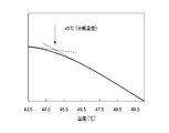
- 6 is a chart of reduced pressure TG of Co 2 (CO) 8 .
- FIG. 1 is a schematic cross-sectional view showing a film forming apparatus according to an embodiment of the present invention.
- the film forming apparatus 100 has a substantially cylindrical chamber 1 that is hermetically configured, in which a susceptor 2 for horizontally supporting a semiconductor wafer W that is a substrate to be processed is an exhaust that will be described later. It arrange
- the susceptor 2 is made of a ceramic such as AlN. Further, a heater 5 is embedded in the susceptor 2, and a heater power source 6 is connected to the heater 5.
- thermocouple 7 is provided near the upper surface of the susceptor 2.
- the signal of the thermocouple 7 is transmitted to a temperature controller 60 described later.
- the temperature controller 60 transmits a command to the heater power supply 6 in accordance with a signal from the thermocouple 7 and controls the heating of the heater 5 to control the wafer W to a predetermined temperature.
- the susceptor 2 is provided with three wafer raising / lowering pins (not shown) so as to be able to project and retract with respect to the surface of the susceptor 2, and protrudes from the surface of the susceptor 2 when the wafer W is transferred. To be.
- a circular hole 1 b is formed in the top wall 1 a of the chamber 1, and a shower head 10 is fitted so as to protrude into the chamber 1 from there.
- the shower head 10 is for discharging a film forming gas supplied from a gas supply mechanism 30 to be described later into the chamber 1, and a gas inlet for introducing a film forming raw material gas into the top plate 11. 12 is provided.
- a gas diffusion space 13 is formed inside the shower head 10, and a number of gas discharge holes 15 are provided in the bottom plate 14 of the shower head 10. The gas introduced into the gas diffusion space 13 from the gas introduction port 12 is discharged into the chamber 1 from the gas discharge hole 15.
- An exhaust chamber 21 protruding downward is provided on the bottom wall of the chamber 1.
- An exhaust pipe 22 is connected to the side surface of the exhaust chamber 21, and an exhaust device 23 having a vacuum pump, a pressure control valve, and the like is connected to the exhaust pipe 22.
- an exhaust device 23 having a vacuum pump, a pressure control valve, and the like is connected to the exhaust pipe 22.
- a loading / unloading port 24 for loading / unloading the wafer W to / from a wafer transfer chamber (not shown) and a gate valve G for opening / closing the loading / unloading port 24 are provided on the side wall of the chamber 1.
- a heater 26 is provided on the wall portion of the chamber 1 so that the inner wall of the chamber 1 can be heated during the film forming process. The heater 26 is supplied with power from a heater power source 27.
- the gas supply mechanism 30 has a film forming material container 31 for storing solid cobalt carbonyl (Co 2 (CO) 8 ) that is a film forming material.
- a heater 32 is provided around the film forming raw material container 31 to heat and vaporize cobalt carbonyl (Co 2 (CO) 8 ), which is a film forming raw material. The heater 32 is supplied with power from a heater power supply 48.
- a gas introduction pipe 33 is inserted into the film forming material container 31 from above.
- a valve 34 is interposed in the gas introduction pipe 33.
- the gas introduction pipe 33 is branched into a CO gas pipe 35 and a carrier gas pipe 36, the CO gas pipe 35 has a CO gas supply source 37 that functions as a CO gas supply mechanism, and the carrier gas pipe 36 has a cobalt carbonyl supply mechanism.
- the carrier gas supply source 38 that functions as A mass flow controller 39 as a flow rate controller and a valve 40 before and after the mass flow controller 39 are interposed in the CO gas piping 35, and a mass flow controller 41 as a flow rate controller and a valve 42 before and after the mass flow controller 39 are interposed in the carrier gas piping 36.
- Ar gas or N 2 gas can be suitably used as the carrier gas.
- CO gas is introduced in order to suppress decomposition of vaporized cobalt carbonyl (Co 2 (CO) 8 ). That is, CO 2 (CO) 8 is decomposed to produce CO, but by supplying CO to the film forming raw material container 31 and increasing the CO concentration, Co 2 (CO) 8 is decomposed and CO 2 The reaction which produces
- the carrier gas is introduced to convey the Co 2 (CO) 8 gas generated by vaporization in the film forming material container 31 to the chamber 1. In addition, you may give the function of carrier gas to CO gas, and the separate carrier gas is unnecessary in that case.
- a film forming material gas supply pipe 43 is inserted into the film forming material tank 31 from above, and the other end of the film forming material gas supply pipe 43 is connected to the gas inlet 12. Then, the Co 2 (CO) 8 gas heated and vaporized by the heater 32 is conveyed by the carrier gas through the film forming raw material gas supply pipe 43 and supplied to the shower head 10 through the gas inlet 12.
- a heater 44 is provided around the film forming material gas supply pipe 43. The heater 44 is supplied with power from a heater power source 49.
- the film forming material gas supply pipe 43 is provided with a flow rate adjusting valve 45, an opening / closing valve 46 immediately downstream thereof, and an opening / closing valve 47 immediately adjacent to the gas inlet 12.
- Dilution gas supplying, for example, Ar gas or N 2 gas as a dilution gas to the other end of the dilution gas pipe 61 connected to the dilution gas supply pipe 61 upstream of the valve 47 of the film forming material gas supply pipe 43
- a gas supply source 62 is connected.
- the dilution gas pipe 61 is provided with a mass flow controller 63 as a flow rate controller and valves 64 before and after the mass flow controller 63.
- the dilution gas also functions as a purge gas and a stabilizing gas.
- thermocouple 51 is attached to the wall of the chamber 1
- a thermocouple 52 is attached in the film forming raw material container 31
- a thermocouple 53 is attached to the film forming raw material gas supply pipe 43
- These thermocouples 51, 52, 53 are connected to a temperature controller 60.
- the temperature detection signals detected by these thermocouples including the thermocouple 7 described above are sent to the temperature controller 60.
- the heater controller 6, 27, 48, 49 described above is connected to the temperature controller 60.
- the temperature controller 60 sends a control signal to the heater power sources 6, 27, 48, 49 in accordance with the detection signals of the thermocouples 7, 51, 52, 53 described above, and the temperature of the susceptor 2 and the wall of the chamber 1
- the temperature, the temperature in the film forming raw material container 31, and the temperature in the film forming raw material gas supply pipe 43 are controlled.
- Cobalt carbonyl (Co 2 (CO) 8 ) which is a film forming raw material, is vaporized by being heated by the heater 32 in the film forming raw material container 31 and heated in the film forming raw material gas supply pipe 43 by the heater 44. In this state, the carbon carbonyl (Co 2 (CO) 8 ) is heated at a temperature lower than the decomposition start temperature by the temperature controller 60. Specifically, as will be described later, since the decomposition start temperature grasped by the reduced pressure TG (thermogravimetric analyzer) of cobalt carbonyl is 45 ° C., it is preferably controlled to be less than 45 ° C.
- the temperature of the wafer W during film formation is preferably controlled to 120 to 300 ° C.
- the temperature of the wall (inner wall) of the chamber 1 is Co 2 (CO) 8 gas. It is preferred that the temperature be controlled below the decomposition temperature.
- the film forming apparatus 100 includes a control unit 70, and the control unit 70 controls each component, for example, a temperature controller 60, an exhaust device 23, a mass flow controller, a flow rate adjusting valve, a valve, and the like. With respect to the temperature controller 60, the temperature of the portion to be controlled by the temperature controller 60 is set.
- the control unit 70 includes a process controller 71 including a microprocessor (computer), a user interface 72, and a storage unit 73. Each component of the film forming apparatus 100 is electrically connected to the process controller 71 for control.
- the user interface 72 is connected to the process controller 71, and a keyboard on which an operator inputs a command to manage each component of the film forming apparatus 100, and an operating status of each component of the film forming apparatus 100.
- the storage unit 73 is also connected to the process controller 71, and the storage unit 73 corresponds to a control program for realizing various processes executed by the film forming apparatus 100 under the control of the process controller 71 and processing conditions.
- a control program for causing each component of the film forming apparatus 100 to execute a predetermined process, that is, a process recipe, various databases, and the like are stored.
- the processing recipe is stored in a storage medium (not shown) in the storage unit 73.
- the storage medium may be a fixed medium such as a hard disk or a portable medium such as a CDROM, DVD, or flash memory. Moreover, you may make it transmit a recipe suitably from another apparatus via a dedicated line, for example.
- a predetermined processing recipe is called from the storage unit 53 in accordance with an instruction from the user interface 52 and is executed by the process controller 51, so that the film forming apparatus 100 can control the process controller 71. Desired processing is performed.
- Solid cobalt carbonyl (Co 2 (CO) 8 ) is charged as a film forming raw material in the film forming raw material container 31, and the temperature of the susceptor 2 in the chamber 1 and the wall of the chamber 1 are set. The temperature of the part is controlled to the temperature at the time of film formation.
- the gate valve G is opened, the wafer W is introduced into the chamber 1 by a transfer device (not shown), and placed on the susceptor 2.
- the wafer W has a SiOxCy insulating film (x and y are positive numbers) or an organic insulating film on the surface, and Al serving as a lower wiring.
- Cu or W conductors are used.
- a wafer W having a silicon substrate surface serving as a source / drain electrode exposed on the surface or a polysilicon film formed on the surface is used.
- the inside of the chamber 1 is evacuated by the exhaust device 23 so that the pressure in the chamber 1 is 10 to 5000 Pa (0.075 to 37.5 Torr), and the susceptor 2 is heated by the heater 5 so that the temperature of the susceptor 2 (wafer temperature). Is preferably controlled to 120 to 300 ° C.
- valve 46 is closed, the valves 47 and 64 are opened, and the dilution gas is supplied from the dilution gas supply source 62 into the chamber 1 for stabilization.
- the film forming raw material container 31 and the film forming raw material gas supply pipe 43 are heated by the heaters 32 and 44 while strictly controlling the temperature to a predetermined temperature lower than the decomposition start temperature of cobalt carbonyl (Co 2 (CO) 8 ).
- the supply of the dilution gas is stopped, or the CO gas and the carrier gas are supplied to the film forming raw material container 31 while the dilution gas is supplied at a predetermined flow rate.
- the Co 2 (CO) 8 gas vaporized in the film forming raw material container 31 with the opening 46 is conveyed through the film forming raw material gas supply pipe 43 by the carrier gas and supplied into the chamber 1 through the shower head 10.
- the Co 2 (CO) 8 gas supplied into the chamber 1 reaches the surface of the wafer W heated to a predetermined temperature by the heater 5 in the susceptor 2, where it is thermally decomposed to form a Co film.
- a purge process is performed.
- the purge process after the supply of the carrier gas to the film forming raw material tank 31 is stopped and the supply of Co 2 (CO) 8 is stopped, the vacuum pump of the exhaust device 23 is turned off, and the dilution gas supply source 62 The chamber 1 is purged by flowing the dilution gas into the chamber 1 as a purge gas.
- the gate valve G is opened, and the wafer W is unloaded through the loading / unloading port 24 by a transfer device (not shown). Thus, a series of steps for one wafer W is completed.
- the film forming raw material container 31 and the film forming raw material gas supply pipe 43 are controlled to a temperature lower than the decomposition start temperature of the Co 2 (CO) 8 gas.
- the temperature of the Co 2 (CO) 8 gas generated by vaporization in the raw material container 31 is less than the decomposition start temperature from the film forming raw material container 31 through the film forming raw material gas supply pipe 43 into the chamber 1.
- Decomposition of Co 2 (CO) 8 can be suppressed.
- the CO concentration in the film increases, and the reaction in which Co 2 (CO) 8 is decomposed to generate CO can be suppressed.
- the temperature at which Co 2 (CO) 8 is vaporized and the temperature at which the generated Co 2 (CO) 8 gas is transported to the chamber 1 are set to a temperature lower than the decomposition start temperature of the Co 2 (CO) 8 gas.
- CO gas capable of suppressing the decomposition of the Co 2 (CO) 8 gas is introduced into the film forming material container 31, the decomposition reaction in the process of vaporizing the Co 2 (CO) 8 and supplying it into the chamber Can be suppressed very effectively, and a decomposition reaction can be caused almost only on the wafer W. Therefore, reproducible Co film formation can be realized.
- the ligand CO is further decomposed to generate carbon and oxygen, and CO 2 (CO )
- CO 2 (CO ) When x is deposited on the wafer W, carbon and oxygen are generated also on the wafer W, so that these are taken into the Co film as impurities.
- the decomposition of the Co 2 (CO) 8 gas is suppressed until reaching the wafer W as in the present embodiment, the CO gas generated by the decomposition of the Co 2 (CO) 8 on the surface of the wafer W is further decomposed. Since it is quickly discharged from the chamber 1 without being carried out, carbon and oxygen are prevented from being taken into the Co film as impurities, and a Co film with few impurities can be obtained.
- the Co 2 (CO) 8 gas decomposition product reduces the reliability of the remaining devices in the pipe or the like
- the Co film formed in the chamber or the like can be minimized and the maintainability of the apparatus can be made extremely high.
- the vaporization temperature of Co 2 (CO) 8 (temperature of the film forming raw material container 31) and the transport temperature (temperature in the film forming raw material gas supply pipe 43) ) Must be controlled to a temperature with a margin of, for example, 35 ° C. or less in consideration of safety, and the amount of generated Co 2 (CO) 8 gas is limited.
- the CO 2 (CO) 8 vaporization temperature and the transport temperature are started to be decomposed by introducing CO gas into the film forming raw material container 31 in addition to these temperature controls as in this embodiment. It becomes possible to control to a higher temperature within the range lower than the temperature, and it is possible to increase the generation amount of Co 2 (CO) 8 gas. Thereby, the throughput of the film forming process can be increased.
- the decomposition temperature of a compound such as Co 2 (CO) 8 gas is usually grasped by DTA (differential thermal analysis), and the decomposition start temperature of Co 2 (CO) 8 gas obtained by DTA is 51 ° C., This temperature is very close to 52 ° C. which is the start of decomposition described in the literature (THE MERCK 10th edition 3067.).
- the decomposition start temperature was 45 ° C. as shown in FIG. Judging from this result, it is preferable to control the heating temperature of the film forming raw material container 31 and the film forming raw material gas supply pipe 43 to less than 45 ° C. Since the lower limit is effectively room temperature, it is preferable to control the temperature to be room temperature or higher and lower than 45 ° C.
- the film formation temperature since the decomposition end temperature of the Co 2 (CO) 8 gas obtained by DTA is 120 ° C., if it is 120 ° C. or higher, Co 2 (CO ) 8 gas can be completely decomposed into Co and CO. On the other hand, if it exceeds 300 ° C., Co will aggregate. Therefore, the film forming temperature is preferably 120 to 300 ° C.
- the temperature of the wall (inner wall) of the chamber 1 is preferably lower than the decomposition temperature of the Co 2 (CO) 8 gas. Thereby, it is possible to prevent the Co 2 (CO) 8 gas reaching the inner wall of the chamber 1 from being decomposed and increasing impurities in the Co film.
- the Co film formed as described above is suitable as a seed film for Cu wiring formed by electrolytic plating. It can also be used as a base film for a CVD-Cu film. Furthermore, when used as a contact layer, after the Co film is formed on the surface of the silicon substrate or the polysilicon film as described above, heat treatment for silicidation is performed in an inert gas atmosphere or a reducing gas atmosphere. Do. The heat treatment temperature at this time is preferably 450 to 800 ° C.
- the CO gas is introduced into the film forming raw material container, and the temperature in the film forming raw material container and the piping is controlled to be lower than the decomposition start temperature of cobalt carbonyl. It can be sufficiently suppressed up to the substrate, and film formation with high reproducibility can be performed. In addition, the decomposition product of cobalt carbonyl is suppressed from being taken into the Co film as impurities, and a Co film with few impurities can be formed.
- the present invention can be variously modified without being limited to the above embodiment.
- the present invention is not limited thereto, and other substrates such as a flat panel display (FPD) substrate may be used.
- FPD flat panel display
Abstract
Description
また、本発明の他の目的は、そのような成膜方法を実行するためのプログラムを記憶した記憶媒体を提供することにある。
前記成膜原料容器から前記配管を介して前記処理容器に気体状のコバルトカルボニルを供給するためのコバルトカルボニル供給機構と、前記成膜原料容器および前記配管の温度をコバルトカルボニルの分解開始温度未満に制御する制御部と、前記成膜原料容器内にCOガスを供給するCOガス供給機構とを具備する成膜装置が提供される。
図1は、本発明の一実施形態に係る成膜装置を示す略断面である。
この成膜装置100は、気密に構成された略円筒状のチャンバー1を有しており、その中には被処理基板である半導体ウエハWを水平に支持するためのサセプタ2が、後述する排気室の底部からその中央下部に達する円筒状の支持部材3により支持された状態で配置されている。このサセプタ2はAlN等のセラミックスからなっている。また、サセプタ2にはヒーター5が埋め込まれており、このヒーター5にはヒーター電源6が接続されている。一方、サセプタ2の上面近傍には熱電対7が設けられている。熱電対7の信号は後述する温度コントローラ60に伝送されるようになっている。そして、温度コントローラ60は熱電対7の信号に応じてヒーター電源6に指令を送信し、ヒーター5の加熱を制御してウエハWを所定の温度に制御するようになっている。なお、サセプタ2には3本のウエハ昇降ピン(図示せず)がサセプタ2の表面に対して突没可能に設けられており、ウエハWを搬送する際に、サセプタ2の表面から突出した状態にされる。
次に、以上のように構成された成膜装置を用いて行われる成膜方法について説明する。
なお、本発明は、上記実施の形態に限定されることなく種々変形可能である。例えば、成膜原料であるコバルトカルボニルの供給手法についても上記実施形態の手法に限定する必要はなく、種々の方法を適用することができる。
Claims (8)
- 基板上にCo膜を成膜する成膜装置であって、
基板が収容される処理容器と、
前記処理容器内で基板を加熱するための加熱機構と、
前記処理容器外に配置された、成膜原料としてコバルトカルボニルを収容する成膜原料容器と、
前記成膜原料容器から気体状のコバルトカルボニルを前記処理容器に供給するための配管と、
前記処理容器内を減圧排気する排気機構と、
前記成膜原料容器から前記配管を介して前記処理容器に気体状のコバルトカルボニルを供給するためのコバルトカルボニル供給機構と、
前記成膜原料容器および前記配管の温度をコバルトカルボニルの分解開始温度未満に制御する制御部と、
前記成膜原料容器内にCOガスを供給するCOガス供給機構と
を具備する成膜装置。 - 前記制御部は、前記成膜原料容器および前記配管の温度を45℃未満に制御する請求項1に記載の成膜装置。
- 前記加熱機構は、基板を120~300℃の範囲の温度で加熱する請求項1に記載の成膜装置。
- 基板が収容される処理容器と、前記処理容器内で基板を加熱するための加熱機構と、前記処理容器外に配置された、成膜原料としてコバルトカルボニルを収容する成膜原料容器と、前記成膜原料容器から気体状のコバルトカルボニルを前記処理容器に供給するための配管と、前記処理容器内を減圧排気する排気機構とを有する成膜装置を用いて、基板上にCo膜を成膜する成膜方法であって、
前記成膜原料容器内にCOガスを供給することと、
前記成膜原料容器内のコバルトカルボニルを気化させて前記配管を介して前記処理容器に気体状のコバルトカルボニルを供給することと、
前記成膜原料容器内および前記配管内の温度をコバルトカルボニルの分解開始温度未満に制御することと、
前記処理容器内に供給された気体状のコバルトカルボニルを加熱された基板上で分解させて基板上にCo膜を堆積させることと
を有する成膜方法。 - 前記成膜原料容器内および前記配管内の温度を45℃未満に制御する請求項4に記載の成膜方法。
- Co膜を堆積させる際の基板表面の加熱温度を120~300℃の範囲に制御する請求項4に記載の成膜方法。
- 前記Co膜はシリコンの上に成膜され、成膜後、不活性ガス雰囲気または還元ガス雰囲気でシリサイド化のための熱処理が行われる請求項4に記載の成膜方法。
- コンピュータ上で動作し、基板が収容される処理容器と、前記処理容器内で基板を加熱するための加熱機構と、前記処理容器外に配置された、成膜原料としてコバルトカルボニルを収容する成膜原料容器と、前記成膜原料容器から気体状のコバルトカルボニルを前記処理容器に供給するための配管と、前記処理容器内を減圧排気する排気機構とを有する成膜装置を制御するためのプログラムが記憶された記憶媒体であって、前記プログラムは、実行時に、前記成膜原料容器内にCOガスを供給することと、前記成膜原料容器内のコバルトカルボニルを気化させて前記配管を介して前記処理容器に気体状のコバルトカルボニルを供給することと、前記成膜原料容器内および前記配管内の温度をコバルトカルボニルの分解開始温度未満に制御することと、前記処理容器内に供給された気体状のコバルトカルボニルを加熱された基板上で分解させて基板上にCo膜を堆積させることとを有する成膜方法が行われるように、コンピュータに前記成膜装置を制御させる記憶媒体。
Priority Applications (1)
| Application Number | Priority Date | Filing Date | Title |
|---|---|---|---|
| US13/395,683 US20120171365A1 (en) | 2009-09-17 | 2010-08-27 | Film forming apparatus, film forming method and storage medium |
Applications Claiming Priority (2)
| Application Number | Priority Date | Filing Date | Title |
|---|---|---|---|
| JP2009-215416 | 2009-09-17 | ||
| JP2009215416A JP2011063850A (ja) | 2009-09-17 | 2009-09-17 | 成膜装置、成膜方法および記憶媒体 |
Publications (1)
| Publication Number | Publication Date |
|---|---|
| WO2011033918A1 true WO2011033918A1 (ja) | 2011-03-24 |
Family
ID=43758527
Family Applications (1)
| Application Number | Title | Priority Date | Filing Date |
|---|---|---|---|
| PCT/JP2010/064574 WO2011033918A1 (ja) | 2009-09-17 | 2010-08-27 | 成膜装置、成膜方法および記憶媒体 |
Country Status (5)
| Country | Link |
|---|---|
| US (1) | US20120171365A1 (ja) |
| JP (1) | JP2011063850A (ja) |
| KR (1) | KR20120053032A (ja) |
| TW (1) | TW201124555A (ja) |
| WO (1) | WO2011033918A1 (ja) |
Cited By (1)
| Publication number | Priority date | Publication date | Assignee | Title |
|---|---|---|---|---|
| JP2012172252A (ja) * | 2011-02-24 | 2012-09-10 | Tokyo Electron Ltd | 成膜方法および記憶媒体 |
Families Citing this family (6)
| Publication number | Priority date | Publication date | Assignee | Title |
|---|---|---|---|---|
| JP5659041B2 (ja) * | 2011-02-24 | 2015-01-28 | 東京エレクトロン株式会社 | 成膜方法および記憶媒体 |
| JP2012198449A (ja) | 2011-03-23 | 2012-10-18 | Nitto Denko Corp | 偏光膜および偏光フィルム |
| DE102014115497A1 (de) * | 2014-10-24 | 2016-05-12 | Aixtron Se | Temperierte Gaszuleitung mit an mehreren Stellen eingespeisten Verdünnungsgasströmen |
| KR101941097B1 (ko) * | 2015-11-24 | 2019-01-23 | 주식회사 원익테라세미콘 | 가스 공급 및 배기 장치 |
| MY189436A (en) * | 2016-04-12 | 2022-02-11 | Picosun Oy | Coating by ald for suppressing metallic whiskers |
| US20180134738A1 (en) * | 2016-11-01 | 2018-05-17 | Versum Materials Us, Llc | Disubstituted alkyne dicobalt hexacarbonyl compounds, method of making and method of use thereof |
Citations (5)
| Publication number | Priority date | Publication date | Assignee | Title |
|---|---|---|---|---|
| JP2007247062A (ja) * | 2006-03-16 | 2007-09-27 | Tokyo Electron Ltd | パーティクルの形成を低減する金属層成膜システム、気相原料分配システムおよび方法 |
| JP2007270355A (ja) * | 2006-03-30 | 2007-10-18 | Tokyo Electron Ltd | 金属カルボニル先駆体を利用した堆積プロセスの初期化方法及びシステム |
| JP2007277719A (ja) * | 2006-03-29 | 2007-10-25 | Tokyo Electron Ltd | 薄膜堆積システム内における基板の周辺端部での一酸化炭素中毒を抑制する方法及び装置 |
| JP2008520834A (ja) * | 2004-11-23 | 2008-06-19 | 東京エレクトロン株式会社 | 金属カルボニル前駆体から金属層を堆積する方法 |
| JP2008520835A (ja) * | 2004-11-23 | 2008-06-19 | 東京エレクトロン株式会社 | 金属カルボニル前駆体からの金属層の成膜速度を上げる方法 |
-
2009
- 2009-09-17 JP JP2009215416A patent/JP2011063850A/ja active Pending
-
2010
- 2010-08-27 KR KR1020127006193A patent/KR20120053032A/ko not_active Application Discontinuation
- 2010-08-27 WO PCT/JP2010/064574 patent/WO2011033918A1/ja active Application Filing
- 2010-08-27 US US13/395,683 patent/US20120171365A1/en not_active Abandoned
- 2010-09-16 TW TW099131354A patent/TW201124555A/zh unknown
Patent Citations (5)
| Publication number | Priority date | Publication date | Assignee | Title |
|---|---|---|---|---|
| JP2008520834A (ja) * | 2004-11-23 | 2008-06-19 | 東京エレクトロン株式会社 | 金属カルボニル前駆体から金属層を堆積する方法 |
| JP2008520835A (ja) * | 2004-11-23 | 2008-06-19 | 東京エレクトロン株式会社 | 金属カルボニル前駆体からの金属層の成膜速度を上げる方法 |
| JP2007247062A (ja) * | 2006-03-16 | 2007-09-27 | Tokyo Electron Ltd | パーティクルの形成を低減する金属層成膜システム、気相原料分配システムおよび方法 |
| JP2007277719A (ja) * | 2006-03-29 | 2007-10-25 | Tokyo Electron Ltd | 薄膜堆積システム内における基板の周辺端部での一酸化炭素中毒を抑制する方法及び装置 |
| JP2007270355A (ja) * | 2006-03-30 | 2007-10-18 | Tokyo Electron Ltd | 金属カルボニル先駆体を利用した堆積プロセスの初期化方法及びシステム |
Cited By (1)
| Publication number | Priority date | Publication date | Assignee | Title |
|---|---|---|---|---|
| JP2012172252A (ja) * | 2011-02-24 | 2012-09-10 | Tokyo Electron Ltd | 成膜方法および記憶媒体 |
Also Published As
| Publication number | Publication date |
|---|---|
| KR20120053032A (ko) | 2012-05-24 |
| US20120171365A1 (en) | 2012-07-05 |
| TW201124555A (en) | 2011-07-16 |
| JP2011063850A (ja) | 2011-03-31 |
Similar Documents
| Publication | Publication Date | Title |
|---|---|---|
| JP5225957B2 (ja) | 成膜方法および記憶媒体 | |
| US20120183689A1 (en) | Ni film forming method | |
| WO2011033918A1 (ja) | 成膜装置、成膜方法および記憶媒体 | |
| KR101334946B1 (ko) | 금속 실리사이드막의 형성 방법 | |
| JP2007154297A (ja) | 成膜方法および成膜装置 | |
| US20090029047A1 (en) | Film-forming apparatus and film-forming method | |
| WO2010103879A1 (ja) | Cu膜の成膜方法および記憶媒体 | |
| JP5661006B2 (ja) | ニッケル膜の成膜方法 | |
| WO2010103881A1 (ja) | Cu膜の成膜方法および記憶媒体 | |
| JP7325261B2 (ja) | 基板処理方法及び基板処理装置 | |
| WO2010095498A1 (ja) | Cu膜の成膜方法および記憶媒体 | |
| US8697572B2 (en) | Method for forming Cu film and storage medium | |
| JP5659040B2 (ja) | 成膜方法および記憶媒体 | |
| US20120064247A1 (en) | Method for forming cu film, and storage medium | |
| JP5659041B2 (ja) | 成膜方法および記憶媒体 | |
| JP5656683B2 (ja) | 成膜方法および記憶媒体 | |
| KR101237634B1 (ko) | 성막 방법 및 성막 장치 | |
| JP2012175073A (ja) | 成膜方法および記憶媒体 | |
| JP2013209701A (ja) | 金属膜の成膜方法 | |
| JP2009130108A (ja) | 基板処理装置及び半導体装置の製造方法 | |
| JP2010212323A (ja) | Cu膜の成膜方法および記憶媒体 | |
| JP2010189727A (ja) | Cu膜の成膜方法および記憶媒体 | |
| JP2011168815A (ja) | 成膜方法及び成膜装置 |
Legal Events
| Date | Code | Title | Description |
|---|---|---|---|
| 121 | Ep: the epo has been informed by wipo that ep was designated in this application |
Ref document number: 10817031 Country of ref document: EP Kind code of ref document: A1 |
|
| ENP | Entry into the national phase |
Ref document number: 20127006193 Country of ref document: KR Kind code of ref document: A |
|
| WWE | Wipo information: entry into national phase |
Ref document number: 13395683 Country of ref document: US |
|
| NENP | Non-entry into the national phase |
Ref country code: DE |
|
| 122 | Ep: pct application non-entry in european phase |
Ref document number: 10817031 Country of ref document: EP Kind code of ref document: A1 |