WO2011027453A1 - 制御ユニット、伝送装置及びスイッチ制御方法 - Google Patents
制御ユニット、伝送装置及びスイッチ制御方法 Download PDFInfo
- Publication number
- WO2011027453A1 WO2011027453A1 PCT/JP2009/065441 JP2009065441W WO2011027453A1 WO 2011027453 A1 WO2011027453 A1 WO 2011027453A1 JP 2009065441 W JP2009065441 W JP 2009065441W WO 2011027453 A1 WO2011027453 A1 WO 2011027453A1
- Authority
- WO
- WIPO (PCT)
- Prior art keywords
- line
- test
- switch
- control unit
- unit
- Prior art date
- Legal status (The legal status is an assumption and is not a legal conclusion. Google has not performed a legal analysis and makes no representation as to the accuracy of the status listed.)
- Ceased
Links
Images










Classifications
-
- H—ELECTRICITY
- H04—ELECTRIC COMMUNICATION TECHNIQUE
- H04L—TRANSMISSION OF DIGITAL INFORMATION, e.g. TELEGRAPHIC COMMUNICATION
- H04L12/00—Data switching networks
- H04L12/28—Data switching networks characterised by path configuration, e.g. LAN [Local Area Networks] or WAN [Wide Area Networks]
- H04L12/42—Loop networks
-
- H—ELECTRICITY
- H04—ELECTRIC COMMUNICATION TECHNIQUE
- H04L—TRANSMISSION OF DIGITAL INFORMATION, e.g. TELEGRAPHIC COMMUNICATION
- H04L43/00—Arrangements for monitoring or testing data switching networks
- H04L43/08—Monitoring or testing based on specific metrics, e.g. QoS, energy consumption or environmental parameters
- H04L43/0805—Monitoring or testing based on specific metrics, e.g. QoS, energy consumption or environmental parameters by checking availability
- H04L43/0811—Monitoring or testing based on specific metrics, e.g. QoS, energy consumption or environmental parameters by checking availability by checking connectivity
-
- H—ELECTRICITY
- H04—ELECTRIC COMMUNICATION TECHNIQUE
- H04L—TRANSMISSION OF DIGITAL INFORMATION, e.g. TELEGRAPHIC COMMUNICATION
- H04L43/00—Arrangements for monitoring or testing data switching networks
- H04L43/10—Active monitoring, e.g. heartbeat, ping or trace-route
-
- H—ELECTRICITY
- H04—ELECTRIC COMMUNICATION TECHNIQUE
- H04L—TRANSMISSION OF DIGITAL INFORMATION, e.g. TELEGRAPHIC COMMUNICATION
- H04L43/00—Arrangements for monitoring or testing data switching networks
- H04L43/50—Testing arrangements
Definitions
- the embodiment studied here relates to a method for controlling a switch that switches a used line between two lines forming a 1 + 1 redundant configuration.
- the 1 + 1 redundant configuration includes one working line and one protection line.
- the transmitting apparatus sends the same signal to both the working line and the protection line, and the receiving apparatus switches the line to be used between the working line and the protection line.
- the receiving apparatus includes a switch for switching a used line between a working line and a protection line.
- a 1 + 1 redundant configuration includes, for example, a unidirectional path switching ring system (UPSR: “Unidirectional” Path “Switched” Ring).
- UPSR unidirectional path switching ring system
- a cross-connect device provided at each branch point of a network transmission path and provided with a means for setting a transmission path between communication devices and a means for setting a bypass route when a failure occurs in the transmission path has been proposed.
- the cross-connect device includes means for confirming connectivity according to a predetermined timing with another adjacent cross-connect device that can be a detour route.
- the means for confirming includes means for confirming connectivity with another cross-connect device by inserting a code for confirming connection into the F2 byte of the path overhead of the standard STS1 signal.
- the relay unit connects the input and output of the low-order group signals of both multiplex transmission devices, the signal switching unit switches and outputs the low-order group signals of both multiplex transmission devices, and the signal distribution unit outputs the low-order group signals.
- the signal switching unit switches and outputs the low-order group signals of both multiplex transmission devices, and the signal distribution unit outputs the low-order group signals.
- Low-order group signals to be relayed or dropped at each station can be set arbitrarily, and low-order group signals in different directions can be selected and dropped at any station by switching the signal switching means. 2 routes.
- the multiplex transmission apparatus is provided with a POH insertion means for inserting the F2 byte into the path overhead at the time of switching of the signal switching means and a POH termination means for terminating the F2 byte. Switching of the switching means is performed. Also, the multiplex transmission apparatus is provided with SOH insertion means for inserting the F1 byte into the section overhead and SOH termination means for terminating the F1 byte at each slave station when an abnormality in the received signal and a data error in the high-order group frame are detected. The clock switching means switches between the working and standby clocks according to the F1 byte.
- a transmission apparatus that can establish a line test without terminating overhead information contained in a received signal and check the line state.
- the transmission apparatus recognizes the reception of the test pattern signal, the test pattern signal generating means for generating the test pattern signal, the test pattern signal detecting means for detecting the test pattern signal generated by the test pattern signal generating means, and receiving the test pattern signal.
- Line test setting means for performing line test setting.
- This transmission apparatus includes a corresponding path of the path test specified by the local station side transmission apparatus that performs test control and an overhead (SP byte) for notifying the opposite side transmission apparatus of the execution of the path test, and the local station side transmission apparatus.
- the opposite station side transmission device uses a main signal to which an overhead (RP byte) for returning the usage status of the test relevant path is assigned, and further, information for notifying the test relevant path of the path test and the execution of the path test.
- RP byte overhead
- a circuit that collects the collected information as SP bytes into the main signal, a circuit that separates the SP bytes from the received main signal, and a corresponding path of the path test indicated by the separated SP bytes A circuit that collects the usage state of the RP byte from the control unit, a circuit that inserts the collected information into the main signal as an RP byte, a circuit that separates the RP byte from the received main signal And a circuit which informs the control unit of the embodiment permission determination to pass the test by using state of the test appropriate path path test indicated RP bytes apart.
- the receiving apparatus selects either the working line or the protection line as the used line.
- the receiving apparatus cannot determine whether the target of the line test is the active line or the protection line, so the above switch is set so that the test signal can be taken out from the line under test. I can't control it.
- a switch that switches a used line between the two lines in the receiving apparatus is one line to be tested.
- the purpose is to be able to select.
- a control unit controls a switch that switches a used line between two lines forming a 1 + 1 redundant configuration.
- the control unit selects a test target determination unit that determines which of the above two lines is a circuit test target line, and a line that is determined to be a circuit test target by the test target determination unit as a use line.
- a switch control unit for fixing the selection state of the switch.
- the switch of the receiving apparatus that switches the used line between the two lines forming the 1 + 1 redundant configuration can select one of the two lines to be tested.
- FIG. 10 is an explanatory diagram of a test access line connection process in the node device B.
- FIG. 11 is an explanatory diagram (part 1) of the operation of the STS switch fabrication unit in the node device B.
- FIG. 10 is an explanatory diagram of test access line connection processing in the node device C;
- FIG. 11 is an explanatory diagram (part 1) of the operation of the STS switch fabrication unit in the node device C;
- FIG. 6 is an explanatory diagram of a test access line disconnection process in the node apparatus C.
- FIG. 12 is an explanatory diagram (part 2) of the operation of the STS switch fabrication unit in the node device C.
- FIG. 10 is an explanatory diagram of a test access line disconnection process in the node apparatus B.
- FIG. 11 is an explanatory diagram (part 2) of the operation of the STS switch fabrication unit in the node device B. It is explanatory drawing of a TAP deletion process.
- FIG. 1 is a schematic configuration diagram of a first example of a transmission apparatus according to an embodiment.
- Reference numeral 1 indicates a transmission apparatus
- reference numeral 2 indicates a switch
- reference numeral 3 indicates a control unit
- reference numeral 4 indicates a test object determination unit
- reference numeral 5 indicates a switch control unit.
- Reference numerals L1 and L2 indicate two lines forming a 1 + 1 redundant configuration, and reference numeral Lo indicates an output line through which the transmission apparatus 1 outputs a received signal received via the line L1 and / or the line L2.
- the transmission apparatus 1 is a transmission apparatus on the receiving side that receives a signal transmitted through the line L1 or the line L2 forming the 1 + 1 redundant configuration, and includes a switch 2 and a control unit 3.
- the switch 2 switches the used line between the lines L1 and L2 forming the 1 + 1 redundant configuration. That is, the switch 2 connects one of the lines L1 and L2 selected as a use line for extracting a signal to be output to the output line Lo and the output line Lo.
- the transmission apparatus 1 may switch the used line between the lines L1 and L2 by a unidirectional method.
- the control unit 3 is a processing unit that performs processing for controlling at least the switch 2.
- the control unit 3 includes a test target determination unit 4 and a switch control unit 5.
- the test object determination unit 4 determines which of the line L1 and the line L2 is the line to be subjected to the line test.
- the switch control unit 5 fixes the switch selection state so as to select the line determined as the line test target by the test target determination unit 4 as the used line.
- the line to be tested is specified and is the test target.
- the switch 2 can be controlled to select the other line. For this reason, for example, in the transmission apparatus on the reception side, it is possible to save man-hours such as an operator manually operating the selection state of the switch 2.
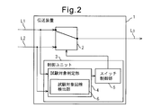
- FIG. 2 is a schematic configuration diagram of a second example of the transmission apparatus according to the embodiment.
- Reference numeral 6 indicates a test target line detection unit 6.
- the same reference numerals as those used in FIG. 1 are attached to the same constituent elements as those shown in FIG.
- the test target determination unit 4 includes a test target line detection unit 6.
- the test target line detection unit 6 detects a predetermined identification signal that flows through the line L1 and / or the line L2. Then, the test target line detection unit 6 detects one of the lines L1 and L2 through which a predetermined identification signal is transmitted as a line to be subjected to a line test.
- the test target determination unit 4 determines that the line detected by the test target line detection unit 6 is a line to be subjected to a line test.
- the switch 2 can be controlled only by sending a specific identification signal to the line L1 or the line L2, and a control signal for causing the switch 2 to select a test target line is separately supplied to the transmission apparatus 1.
- the man-hour and / or structure to give become unnecessary.
- the predetermined identification signal may be included in, for example, a test signal that is sent for a line test or a frame that carries the test signal. By including a predetermined identification signal in the test signal, it is possible to reduce the possibility that a specific identification signal is erroneously sent to a line that is not a test target line.
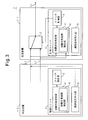
- FIG. 3 is a schematic configuration diagram of a first example of the communication network according to the embodiment.
- Reference numerals 1-1 and 1-2 denote transmission apparatuses
- reference numeral 7 denotes a communication network
- reference numeral 8 denotes an identification information insertion unit 8.
- the transmission apparatuses 1-1 and 1-2 have the same configuration as the transmission apparatus 1 in FIG. 1, and the same components as those shown in FIG. The same reference numerals are assigned.
- the transmission apparatus 1-1 is a transmission apparatus on the receiving side that receives a signal transmitted through the line L1 or the line L2 forming the 1 + 1 redundant configuration.
- the transmission apparatus 1-2 is a transmission apparatus on the transmission side that transmits a signal to the transmission apparatus 1-1 via the line L1 or the line L2, or relays a signal transmitted by such a transmission apparatus on the transmission side. It is a transmission device.
- control unit 3 includes an identification information insertion unit 8.
- the identification information insertion unit 8 inserts predetermined identification information detected by the test target line detection unit 6 into a signal transmitted on the line to be tested.
- predetermined identification information used for specifying a line to be subjected to a line test is inserted into a signal transmitted on the test line which is the line L1 or the line L2, and transmission on the receiving side is performed. It is possible to instruct the test target determination unit 4 of the apparatus 1-1 of the line to be subjected to the line test.
- the identification information insertion unit 8 for example, when the transmission apparatus 1-2 including the identification information insertion unit 8 is at the start point of the section to be subjected to the line test, gives a predetermined identification to the signal to be sent to the line to be subjected to the line test. Information may be inserted. In this way, by allowing the predetermined identification information to flow from the transmission device 1-2 at the start point of the line target section, it becomes easier to flow the predetermined identification information to the test target line, and the end point In this transmission apparatus 1-1, the line to be tested can be detected more reliably.
- the identification information insertion unit 8 may insert predetermined identification information into, for example, a test signal or a frame carrying the test signal. By inserting the predetermined identification information into the test signal and the frame carrying the test signal, it is possible to reduce the risk of erroneously flowing the predetermined identification information on a line different from the line subjected to the line test.
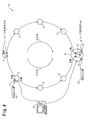
- FIG. 4 is a schematic configuration diagram of a second example of the communication network according to the embodiment.
- Reference numeral 10 indicates a ring network, and A to H indicate node devices.
- Reference numeral 11 indicates a port for inserting (adding) a user signal from the low-order group line to the ring network 10 in the node equipment A.
- Reference numeral 12 denotes a port that branches (drops) a user signal from the ring network 10 to the low-order group line in the node equipment B.
- Reference numeral 13 indicates a path switch.
- Reference numerals 14 and 15 indicate test access devices, and reference numeral 16 indicates a control terminal.
- the ring network 10 is a network that realizes a multiplexed transmission path according to the UPSR system, and includes node apparatuses A to H arranged in a ring shape and transmission paths that connect them.
- the ring network 10 may be a ring network provided in a SONET (Synchronous Optical NETwork: SDH network) / SDH network.
- a user signal is inserted in the node device A and this user signal is branched in the node device B which is the opposite device of the node device A.
- the user signal inserted at the port 11 is transmitted in both the east direction (E direction) and the west direction (W direction).
- the east direction (E direction) indicates the counterclockwise direction of the ring network 10
- the waist direction (W direction) indicates the clockwise direction of the ring network 10.
- the side on which the signals flowing in the E direction and the W direction advance is referred to as “east side (E side)” and “west side (W side)”, respectively.
- the user signal transmitted in the E direction reaches the node device B via the node devices C to E in the order of the node device C, the node D, and the node device E.
- the user signal transmitted in the W direction reaches the node device B via the node devices F to H in the order of the node device F, the node G, and the node device H.
- the same user signal received from the W side and the E side is input to the path switch (PSW) 13 of the node device B.
- the node device B selects one path through which the user signal with better reception quality is received by the path switch 13, branches the user signal from the selected path, and outputs it from the port 12.
- the circuit test may be a test called “test access”, for example.
- the test access is a test for confirming the transmission quality of each user line on the transmission path on which the user line network is formed.
- Test devices used for test access include test access devices 14 and 15 and a control terminal 16.
- the control terminal 16 sends a command for opening a test access port (TAP) for inputting and outputting a test access signal, which is a test signal, and a command for connecting the TAP to a test target line to node devices at both ends of the test section.
- TAP test access port
- One test access device 14 transmits a test access signal via the TAP of the node device at one end of the test interval
- the other test access device 15 transmits the test access signal via the TAP of the node device at the other end of the test interval.
- the line test is performed by receiving.
- test access device 14 transmits a test access signal via the TAP 17 established in the node device C, and the test access device 15 receives the test access signal via the TAP 18 established in the node device B.
- the line test is performed by monitoring a signal received by the test access device 15.
- the TAP may be connected from the node apparatus C to the line to be tested first.
- the problem that the node device B still cannot determine which path in the E or W direction should be selected by the path switch 13 is not solved.
- the path switch 13 of the node device B is made to select a path through which the test access signal is transmitted and received by means different from the PSW forced fixing switching command and the PSW forced fixing release command.
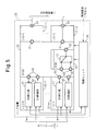
- FIG. 5 is a schematic configuration diagram of the node devices A to H according to the embodiment.
- Reference numeral 20 indicates a node device
- reference numerals 21-1 to 21-n indicate low-order group line interface units (LIU-L)
- reference numerals 22-1 to 22-m indicate high-order group line interface units (LIU-).
- H indicates an STS (Synchronous Transport Signal) switch fabrication section (STSSF)
- STSSF Synchronous Transport Signal
- PSW path switch
- reference numeral 26 indicates a control unit.
- Reference numeral 40 indicates an overhead (OH) termination section
- reference numeral 41 indicates an overhead (OH) insertion section.
- the node device 20 includes low-order group line interface units 21-1 to 21-n, high-order group line interface units 22-1 to 22-m, an STSSF 23, a path switch unit 24, and a control unit 26.
- the low-order group line interface units 21-1 to 21-n input and output signals to and from the low-order group line.
- User signals to be inserted into the ring network 10 are input from the low-order group lines at the low-order group line interface units 21-1 to 21-n.
- the user signal branched from the ring network 10 is output to the low-order group line by the low-order group line interface units 21-1 to 21-n.
- Reference numeral 33 is used to input a signal from the low-order group line interface to the low-order group line interface units 21-1 to 21-n, or from the low-order group line interface units 21-1 to 21-n to the low-order group line. Indicates the port to output.
- the high-order group line interface units 22-1 to 22-m input / output signals to / from the ring network 10 which is a network formed by high-order group lines.
- Each of the high-order group line interface units 22-1 to 22-m includes an OH termination unit 40 and an OH insertion unit 41.
- the OH termination unit 40 terminates a path overhead (POH) added to a frame input from the ring network 10 to the high-order group line interface units 22-1 to 22-m, and outputs the contents of the path overhead to the control unit 26.
- the OH insertion unit 41 inserts a path overhead into a frame output from the high-order group line interface units 22-1 to 22-m to the ring network 10.
- the OH insertion unit 41 may determine a path overhead value according to a signal input from the control unit 26.
- the STSSF 23 is a cross connecting each line connecting the low-order group line interface units 21-1 to 21-n, the high-order group line interface units 22-1 to 22-m, and the path switch 13 in units of paths. Perform connect connection.
- Reference numeral 30 indicates each connection portion to which a line is connected between each high-order group line interface unit 22-1 to 22-m and the STSSF23.
- Reference numeral 31 indicates each connection portion to which a line is connected between each low-order group line interface unit 21-1 to 21 -n and the STSSF 23.
- Reference numeral 32 indicates each connection portion to which a line is connected between the path switch 13 and the STSSF 23.
- the path switch unit 24 includes a path switch 13 that is used to select one of the duplex paths by the UPSR method.
- the path switch 13 is an example of a switch described in the claims.
- the low-order group line interface unit, the high-order group line interface unit, the STSSF, the path switch, and the path switch unit provided in each of the node devices A to H are distinguished from those provided in other node devices. Therefore, a symbol for distinguishing each node device may be added to the end of the reference code.
- the low-order group line interface unit, each high-order group line interface unit, STSSF, path switch, and path switch unit provided in the node device A are the low-order group line interface unit 21a, the high-order group line interface unit 22a, the STSSF 23a, and the path switch, respectively. 13a and path switch unit 24a.
- a plurality of components may be distinguished by adding a number after the symbol for distinguishing each node device.
- the high-order group line interface units provided in the node device A and provided on the E side and the W side may be described as high-order group line interface units 22a1 and 22a2, respectively.
- FIG. 6 is an explanatory diagram of the cross-connect connection of the STSSF 23a of the node device A when the user signal inserted in the node device A is transmitted in both the E direction and the W direction as described above with reference to FIG. .
- the STSSF 23a connects the low-order group line interface unit 21a and the high-order group line interface unit 22a1 on the E side by a cross-connect connection 100.
- the STSSF 23a connects the low-order group line interface unit 21a and the high-order group line interface unit 22a2 on the W side through a cross-connect connection 101.
- the user signal input to the low-order group line interface unit 21a via the port 33 is input to the high-order group line interface units 22a1 and 22a2 on the E side and W side via the cross-connect connections 100 and 101.
- the high-order group line interface units 22a1 and 22a2 transmit the same user signal in the E direction and the W direction, respectively.
- FIG. 7 is an explanatory diagram of the cross-connect connection of the STSSF 23b of the node apparatus B when user signals are received from both the E direction and the W direction as described above with reference to FIG.
- the STSSF 23b connects one of the two inputs of the path switch 13b1 and the high-order group line interface unit 22b1 on the E side by a cross-connect connection 102.
- the STSSF 23b connects the other input of the path switch 13b1 and the high-order group line interface unit 22b2 on the W side by the cross-connect 103.
- the STSSF 23b connects the output unit of the path switch 13b1 and the low-order group line interface unit 21b2 through the cross-connect 104.
- User signals flowing in the W direction and the E direction are received by the high-order group line interface units 22b1 and 22b2 on the E side and the W side, respectively.
- User signals received by the high-order group line interface units 22b1 and 22b2 are input to the path switch 13b1 via the cross-connects 102 and 103, respectively.
- the user signal input from the path selected by the path switch 13b1 is input to the low-order group line interface unit 21b via the cross connect 104.
- the low-order group line interface unit 21b outputs the input user signal to the low-order group line via the port 33b1.
- the control unit 26 controls the cross-connect connection performed by the STSSF 23 and the operation in which the path switch 13 selects one of the duplex paths by the UPSR system.
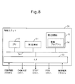
- FIG. 8 is a hardware configuration diagram in which the control unit 26 according to the embodiment is realized using a CPU.
- Reference numeral 50 indicates a CPU
- reference numeral 51 indicates a first storage unit
- reference numeral 52 indicates a second storage unit
- reference numeral 53 indicates an interface.
- the first storage unit 51, the second storage unit 52, and the interface 53 are connected to the CPU 50 via the bus 54.
- the control unit 26 includes a CPU 50, a first storage unit 51, a second storage unit 52, and an interface 53.
- the CPU 50 controls the operation of the control unit 26 by executing the control program 56 stored in the second storage unit 52.
- the first storage unit 51 stores data necessary for the execution of the control program 56 by the CPU 50 and also stores temporary data generated when the control program 56 is executed.
- the first storage unit 51 may be, for example, a random access memory.
- the second storage unit 52 is a non-volatile storage device that stores the control program 56 and various setting data necessary for the operation of the control unit 26.
- the interface 53 is an interface device for transmitting and receiving data between the control terminal 16, the STSSF 23, the path switch unit 24, the OH termination unit 40 and the OH insertion unit 41, and the control unit 26.
- FIG. 9 is a block diagram of the control unit 26 according to the embodiment.
- Reference numeral 60 represents a command processing unit
- reference numeral 61 represents an STSSF control unit
- reference numeral 62 represents a test object determination unit
- reference numeral 63 represents a switch control unit
- reference numeral 64 represents an identification signal insertion unit.
- Reference numeral 65 denotes a test target line detection unit.
- the control unit 26 includes a command processing unit 60, an STSSF control unit 61, a test target determination unit 62, a switch control unit 63, and an identification signal insertion unit 64.
- test access control command a command relating to execution of test access is referred to as “test access control command”.
- Types of test access control commands include, for example, “test access port (TAP) installation command”, “test access line connection command”, “test access line disconnection command”, and “TAP deletion command”.
- test installation command is a command for instructing the establishment of a TAP that inputs or outputs a test access signal used for test access.
- test access line connection command is a command for instructing connection of a test access line through which a test access signal flows by disconnecting the line to be subjected to the line test from the currently operating line and connecting it to the TAP.
- test target line the line subject to the line test may be referred to as “test target line”.
- test access line disconnection command is a command for instructing disconnection of the test access line by disconnecting the test target line from the TAP and reconnecting to the operation line.
- TAP deletion command is a command for instructing deletion of the TAP.
- the command processing unit 60 controls the operations of the STSSF control unit 61 and the switch control unit 63 according to the type of received command.
- the STSSF control unit 61 performs execution and disconnection processing of the cross-connect connection for connecting the test access line according to control by the command processing unit 60.
- the command processing unit 60 of the node device on the receiving side of the test target line receives the “test access line connection command”
- the command processing unit 60 uses a new path switch for test access.
- the command processing unit 60 connects the test target line to one input unit of the test access path switch, and forms the multiplexed line by UPSR by forming a pair with the test target line at the other input unit.
- the STSSF control unit 61 is controlled so as to be connected.
- the command processing unit 60 controls the STSSF control unit 61 to connect the TAP to the output unit of the test access path switch.
- the test target determination unit 62 determines which of the two lines connected to the input unit of the test access path switch is the test target line.
- the test target determination unit 62 includes a test target line detection unit 65.
- the test target line detection unit 65 detects a predetermined test identifier that is sent to the test target line.
- the test target line detection unit 65 detects, as a test target line, one of these lines to which a test identifier indicating execution of test access is transmitted.
- the test identifier is included in the path overhead (POH) defined in the SONET / SDH standard.
- POH path overhead
- the test identifier can be provided using “J1” bytes.
- An arbitrary value can be designated in the J1 byte by a command from the control terminal 16.
- values that are not currently scheduled to be set by the control terminal 16 are 0x00 to 0x1F.
- the test identifier is preferably an identifier that can distinguish between “execution of test access” and “non-execution of test access”.
- “0x15” may be assigned as an identifier representing “execution of test access”
- “0x00” may be assigned as an identifier representing “not performing test access”.
- the value of the test identifier included in the POH is acquired by the OH termination unit 40 shown in FIG. 5 and output to the test target line detection unit 65.
- the test target line detection unit 65 detects a line to be subjected to a line test according to the value of the test identifier received from the OH termination unit 40.
- the test target determination unit 62 determines that the line detected by the test target line detection unit 65 is a line to be subjected to a line test.
- the switch control unit 63 fixes the selection state of the switch so as to select the line determined as the line test target by the test target determination unit 65 as the used line.
- the identification signal insertion unit 64 inserts a test identifier into a signal transmitted on the test target line. When the identification signal insertion unit 64 is provided in the node device at the start point of the test target line, it is transmitted on the test target line in accordance with an instruction from the command processing unit 60 that has received the “test access line connection command”. Insert a test identifier into the POH of the frame.
- the identification signal insertion unit 64 may insert the test identifier into the POH added to the frame that transmits the test access signal input from the test access device.
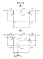
- FIG. 10A and FIG. 10B are explanatory diagrams of the line connection states of the node equipment C and the node equipment B before the start of the test access, respectively.
- the connection part 32 between the path switch and the STSSF, the connection part 31 between the low-order group line interface unit and the STSSF, and the path switch and the low-order group line Description of cross-connect connection between interface units is omitted. The same applies to FIGS. 13 and 22 described below.
- the STSSF 23c of the node device C transfers the operation line to which a signal is input from the node device A side (that is, the W side) to the test target line (that is, the E side line connected to the node device D side) that is a test access target.
- the test target line that is, the E side line connected to the node device D side
- the STSSF 23b of the node device B connects a test target line for inputting a signal from the node device E side (that is, the W side) to one of the input units of the operation line path switch 13b1 through the cross-connect connection 102.
- the STSSF 23b connects a test target line to which a signal is input from the node device H side (that is, the E side) to the other input portion of the path switch 13b1 for the operational line by the cross-connect connection 103.
- the output section of the path switch 13b1 is connected to the operation line port 33b1 on the low-order group line interface unit 21b.
- FIG. 11 is an explanatory diagram of the TAP installation process.
- each of the following operations AA to AC may be a step.
- the TAP installation process in the node apparatus C will be described, but the TAP installation process in the node apparatus B is the same process.
- the command processing unit 60 receives a TAP installation command transmitted from the control terminal 16.
- the TAP installation command includes “TAP number” which is an identifier used to identify a TAP to be newly installed, and an identifier of a port on the low-order group line interface unit used as the TAP to be newly installed. Including the specification.
- operation AB the command processing unit 60 determines whether or not the TAP having the TAP number specified by the TAP installation command can be installed. When the TAP can be installed (operation AB: Y), the command processing unit 60 advances the processing to operation AC. If the TAP cannot be installed (operation AB: N), the command processing unit 60 ends the process.
- the command processing unit 60 enters the TAP of the designated TAP number. That is, the command processing unit 60 stores the TAP number specified by the TAP installation command and the identifier of the port on the low-order group line interface unit used for this TAP in the first storage unit 51. Thereafter, the command processing unit 60 ends the process.
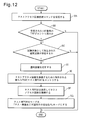
- FIG. 12 is an explanatory diagram of test access line connection processing in the node equipment B.
- the following operations BA to BG may be steps.
- the command processing unit 60 receives a test access line connection command transmitted from the control terminal 16.
- the test access line connection command includes the TAP number of the TAP used for test access and the designation of the test target line.
- the command processing unit 60 determines whether or not the TAP of the TAP number designated by the test access line connection command has already been entered in the node device B. If the TAP has already been entered (operation BB: Y), the command processing unit 60 advances the processing to operation BC. If the TAP has not been entered (operation BB: N), the command processing unit 60 ends the process.
- operation BC the command processing unit 60 determines whether or not there is an operation line designated as a test target line in the test access line connection command. If there is a test target line (operation BC: Y), the command processing unit 60 advances the processing to operation BD. When the test target line does not exist (operation BC: N), the command processing unit 60 ends the process.
- the command processing unit 60 connects the path to be tested and the other line forming a multiplexed line by UPSR paired with this line and the path switch 13b1 as shown in FIG.
- the STSSF control unit 61 is instructed to disconnect 102 and 103.
- the STSSF control unit 61 disconnects the cross-connect connections 102 and 103 according to the instruction from the command processing unit 60.
- the command processing unit 60 selects a new path switch used for test access from a plurality of path switches included in the path switch unit 24b, and enters the selected path switch. That is, the selected test access path switch is stored in the first storage unit 51.
- the command processing unit 60 instructs the STSSF control unit 61 to connect the test access line using the entered test access path switch. That is, the command processing unit 60 performs STSSF control so as to perform a cross-connect connection that connects the test target line and the other line that forms a UPSR multiplexed line by pairing with this line and the test access path switch.
- the unit 61 is instructed.
- the command processing unit 60 instructs the STSSF control unit 61 to perform cross-connect connection for connecting the TAP and the test access path switch.
- the STSSF control unit 61 performs cross-connect connection according to these instructions.
- the test access device 15 is connected to the TAP by the operator.
- the test access line through which the test access signal flows is connected by connecting the test target line, the test access path switch, and the TAP through the cross-connect connection.
- the command processing unit 60 instructs the switch control unit 63 to change the operation mode of the test access path switch to a mode of waiting for reception of a test identifier indicating execution of test access.
- the switch control unit 63 changes the operation mode of the test access path switch in accordance with an instruction from the command processing unit 60.
- FIG. 13 is an explanatory diagram (part 1) of the operation of the STSSF 23b in the node apparatus B.
- Reference numeral 33b2 indicates a TAP
- reference numeral 13b2 indicates a test access path switch.
- the test access line connection command By the test access line connection command, the cross-connect connections 102 and 103 that respectively connected the test target line and the paired line to the two input units of the operation line path switch 13b1 are disconnected.
- cross-connect connections 113 and 114 for connecting the test target line and the line paired with the test target line and the input unit of the test access path switch 13b2 are executed by the test access line connection command.
- a cross-connect connection for connecting the output part of the test access path switch 13b2 and the TAP 33b2 is executed by the test access line connection command.
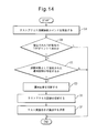
- FIG. 14 is an explanatory diagram of test access line connection processing in the node device C.
- the following operations CA to CF may be steps.
- the command processing unit 60 receives a test access line connection command transmitted from the control terminal 16.
- the command processing unit 60 determines whether or not the TAP of the TAP number designated by the test access line connection command has already been entered in the node device C. If the TAP has already been entered (operation CB: Y), the command processing unit 60 advances the processing to operation CC. If the TAP has not been entered (operation CB: N), the command processing unit 60 ends the process.
- the command processing unit 60 determines whether or not there is an operation line designated as the test target line designated by the test access line connection command. If the test target line exists (operation CC: Y), the command processing unit 60 advances the processing to operation CD. If there is no test target line (operation CC: N), the command processing unit 60 ends the process.
- the command processing unit 60 instructs the STSSF control unit 61 to disconnect the cross-connect connection 110 in FIG. 10A that connects the test target line and the operation line connected to this line by the STSSF 23c. Instruct.
- the STSSF control unit 61 disconnects the cross-connect connection 110 according to the instruction from the command processing unit 60.
- the command processing unit 60 instructs the STSSF control unit 61 to perform a cross-connect connection that connects the test target line and the TAP.
- the STSSF control unit 61 performs cross-connect connection.
- the test access device 14 is connected to the TAP by the operator. By connecting the test target line and the TAP by the cross-connect connection, the test access line through which the test access signal flows is connected.
- the command processing unit 60 instructs the identification signal inserting unit 64 to insert a test identifier indicating execution of the test access into a signal transmitted via the test target line.
- the identification signal inserting unit 64 inserts a test identifier indicating execution of test access into a signal transmitted via the test target line.
- the identification signal inserting unit 64 may insert the test identifier into the signal by setting the value of the J1 byte of the POH added to the frame transmitted via the test target line to “0x15”. .
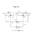
- FIG. 15 is an explanatory diagram (part 1) of the operation of the STSSF 23c in the node apparatus C.
- Reference numeral 33c indicates a TAP, and the cross-connect connection 110 that connects the test target line and the operation line to which a signal is input from the node device A side is disconnected by a test access line connection command.
- a cross-connect connection 115 that connects the test target line and the TAP 33c is executed by the test access line connection command.
- FIG. 16 is an explanatory diagram of the control process of the path switch 13b2.
- the following operations DA to DJ may be steps.
- the switch control unit 63 determines whether or not a test access line using the path switch 13b2 has been connected. When the connection of the test access line is executed (operation DA: Y), the switch control unit 63 shifts the processing to operation DC. When the connection of the test access line is not executed (operation DA: Y), the switch control unit 63 shifts the processing to the operation DB.
- the switch control unit 63 determines that the state of the path switch 13b2 is not yet entered as a test access path switch.
- FIG. 17 is a state transition diagram of the operation mode of the path switch 13b2.
- a state 120 represents a state that has not yet been entered as a test access path switch. Refer to FIG. Thereafter, the switch control unit 63 returns the processing to operation DA.
- the switch control unit 63 shifts the state of the path switch 13b2 to a mode in which it waits for reception of an identifier that is entered as a test access path switch and indicates that the test access is performed. .
- the state of the path switch 13b2 at this point is represented by a state 121 in FIG.
- the node device B receives a signal input to the path switch 13b2 from the E-side and W-side lines.
- the switch control unit 63 determines whether only the J1 byte received from the line on the E side has a value “0x15” indicating execution of test access. When only the J1 byte received from the line on the E side has a value indicating test execution (operation DE: Y), the switch control section 63 shifts the processing to operation DF. In other cases (operation DE: N), the switch control unit 63 shifts the processing to operation DG.
- the switch control unit 63 shifts the operation mode of the path switch 13b2 to the fixed mode in which the line connected from the E side to the node device B is continuously connected to the TAP 33b2.
- the state of the path switch 13b2 at this time is represented by a state 122 in FIG. Refer to FIG. Thereafter, the switch control unit 63 shifts the processing to operation DJ.
- the switch control unit 63 determines whether only the J1 byte received from the W-side line has a value “0x15” indicating that the test access is performed. When only the J1 byte received from the line on the W side has a value indicating the test execution (operation DG: Y), the switch control unit 63 shifts the processing to operation DH. In other cases (operation DG: N), the switch control unit 63 shifts the processing to operation DI.
- the switch control unit 63 shifts the operation mode of the path switch 13b2 to the fixed mode in which the line connected from the W side to the node device B is continuously connected to the TAP 33b2.
- the state of the path switch 13b2 at this time is represented by a state 122 in FIG. Refer to FIG. Thereafter, the switch control unit 63 shifts the processing to operation DJ.
- the switch control unit 63 shifts the operation mode of the path switch 13b2 to the automatic mode.
- the automatic mode is a mode in which a path switch 13b2 automatically selects a line with better line quality among lines for inputting signals from the E side and the W side.
- the state of the path switch 13b2 at this point is represented by a state 121 in FIG.
- the switch control unit 63 determines whether or not the test access line using the path switch 13b2 has been disconnected.
- the switch control unit 63 shifts the state of the path switch 13b2 to a state that has not yet been entered as the test access path switch, and the process is performed in operation DA.
- the state of the path switch 13b2 at this time is represented by the state 120 in FIG. Refer to FIG.
- the switch control unit 63 returns the process to the operation DD.
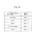
- FIG. 18 is a table showing the transition conditions of the operation mode of the path switch 13b2 that transitions by the above-described operation.
- the path switch 13b2 When the test identifier indicating the test access is received from both the E side and W side lines, the path switch 13b2 operates in the automatic mode. When the test identifier indicating the execution of the test access is received from only one of the lines on the E side and the W side, the path switch 13b2 connects the line that has received the test identifier indicating the execution of the test access to the TAP 33b2. Continue to work in fixed mode. The path switch 13b2 operates in the automatic mode when the test identifier indicating the execution of the test access is not received from either the E side or the W side line, or in other cases.
- test access when a test identifier indicating that test access has been performed is not received, an identifier indicating “not performing test access” is received, and “test access is performed” and “test access is not performed”. This includes the case where none of “Implementation” is received.
- the test identifier indicating the execution of the test access may be continuously transmitted on the test target line while the test access is being performed. Or, the test identifier indicating “execution of test access” is transmitted on the test target line only at the start of test access, and the test identifier indicating “not performing test access” is transmitted on the test target line only at the end of test access. Also good.
- FIG. 19 is an explanatory diagram of a test access line disconnection process in the node device C.
- each of the following operations EA to EE may be a step.
- the command processing unit 60 receives a test access line disconnection command transmitted from the control terminal 16.
- the test access line disconnection command includes designation of the TAP number of the TAP used for the test access line to be disconnected.
- operation EB the command processing unit 60 determines whether or not a test access using the TAP of the designated TAP number is being performed in the node device C. If the test access is being performed (operation EB: Y), the command processing unit 60 shifts the processing to operation EC. When the test access is not performed (operation EB: N), the command processing unit 60 ends the process.
- the command processing unit 60 instructs the identification signal inserting unit 64 to stop inserting a test identifier indicating execution of test access into a signal transmitted via the test target line.
- the identification signal insertion unit 64 stops the insertion of the test identifier indicating the execution of the test access according to the instruction from the command processing unit 60.
- the command processing unit 60 instructs the STSSF control unit 61 to disconnect the test access line. That is, the command processing unit 60 instructs the STSSF control unit 61 to disconnect the cross-connect connection 115 that connects the test target line and the TAP 33c. The STSSF control unit 61 disconnects the cross-connect connection 115 according to the instruction from the command processing unit 60.
- the command processing unit 60 instructs the STSSF control unit 61 to re-execute the cross-connect connection 110 that connects the test target line and the operation line that inputs a signal from the node device A side (W side). To do.
- the STSSF control unit 61 re-executes the cross-connect connection 110 according to the instruction from the command processing unit 60. Thereafter, the command processing unit 60 ends the process.
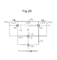
- FIG. 20 is an explanatory diagram (part 2) of the operation of the STSSF 23c in the node device C.
- the cross-connect connection 110 that connects the test target line and the operation line for inputting a signal from the node device A side is performed again.
- the cross-connect connection 115 that connects the test target line and the TAP 33c is disconnected by the test access line disconnection command.
- FIG. 21 is an explanatory diagram of a test access line disconnection process in the node equipment B.
- each of the following operations FA to FD may be a step.
- the command processing unit 60 receives a test access line disconnection command transmitted from the control terminal 16.
- operation FB the command processing unit 60 determines whether or not the test access using the TAP of the designated TAP number is being performed in the node device B.
- operation FB: Y the command processing unit 60 shifts the processing to operation FC.
- operation FB: N the command processing unit 60 ends the process.
- the command processing unit 60 instructs the STSSF control unit 61 to disconnect the test access line. That is, the command processing unit 60 disconnects the cross-connect connections 113 and 114 that connect the test access path switch 13b2 to the test target line and the other line that forms a multiplexed line by UPSR by pairing with the test target line.
- the STSSF control unit 61 is instructed to do so.
- the command processing unit 60 instructs the STSSF control unit 61 to disconnect the cross-connect connection that connects the TAP 33b2 and the test access path switch 13b2.
- the STSSF control unit 61 disconnects these cross-connect connections in accordance with instructions from the command processing unit 60.
- the command processing unit 60 connects the path switch 13b1 used in the operation line, the test target line, and the other line that forms a multiplexed line by UPSR paired with this line to be tested. And the STSSF control unit 61 are instructed to re-execute the steps 103 and 103. The command processing unit 60 instructs the STSSF control unit 61 to re-execute the cross-connect connection that connects the operation line port 33b1 and the path switch 13b1. Thereafter, the command processing unit 60 ends the process.
- FIG. 22 is an explanatory diagram (part 2) of the operation of the STSSF 23b in the node device B.
- the test access line disconnection command By the test access line disconnection command, the cross-connect connections 102 and 103 for connecting the test target line and the paired line to the working line path switch 13b1 are performed again.
- the test access line disconnection command disconnects the cross-connect connections 113 and 114 that connect the test target line and the line paired therewith and the test access path switch 13b2.
- the cross-connect connection for connecting the operation line path switch 13b1 and the operation line port 33b1 is re-executed, and the cross connection for connecting the test access path switch 13b2 and the TAP 33b2 is disconnected.
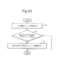
- FIG. 23 is an explanatory diagram of the TAP deletion process.
- the operations GA to GC described below may be steps.
- the TAP deletion process in the node apparatus C will be described, but the TAP setting deletion process in the node apparatus B is the same process.
- the command processing unit 60 receives a TAP deletion command transmitted from the control terminal 16.
- the TAP deletion command includes designation of a “TAP number” used to identify the TAP to be deleted.
- the command processing unit 60 determines whether there is an entry stored for the TAP of the TAP number designated by the TAP deletion command. If there is an entry (operation GB: Y), the command processing unit 60 advances the processing to operation GC. If there is no entry (operation GB: N), the command processing unit 60 ends the process.
- the command processing unit 60 deletes the entry of the TAP number designated by the TAP deletion command from the first storage unit 51. Thereafter, the command processing unit 60 ends the process.
- a test target line is specified from among the multiplexed lines, and the test target line is connected to the TAP.
- the path switch can be controlled to do so.
- the test identifier is included in the overhead of the signal transmitted on the test line.
- a test identifier may be included in the payload of the signal transmitted on the test line.
- the test target line detection unit 65 provided in the control unit 26 may be configured to detect a test identifier included in a payload of a frame that transmits the test line.
Landscapes
- Engineering & Computer Science (AREA)
- Computer Networks & Wireless Communication (AREA)
- Signal Processing (AREA)
- Environmental & Geological Engineering (AREA)
- Data Exchanges In Wide-Area Networks (AREA)
Abstract
1+1冗長構成を形成する2回線L1及びL2の間で使用回線を切り替えるスイッチ2を制御する制御ユニット3は、2回線L1及びL2のどちらが回線試験の対象の回線であるかを判定する試験対象判定部4と、試験対象判定部4により回線試験の対象と判定された回線を使用回線として選択するように、上記のスイッチ2の選択状態を固定するスイッチ制御部5とを備える。
Description
ここで検討される実施例は、1+1冗長構成を形成する2回線の間で使用回線を切り替えるスイッチの制御方法に関する。
1+1冗長構成は、1つの現用回線及び1つの予備回線を備える。送信装置は、現用回線と予備回線の双方に同じ信号を流し、受信装置は、現用回線と予備回線との間で使用する回線を切り替える。受信装置は、現用回線及び予備回線の間で使用回線を切り替えるためのスイッチを備える。このような1+1冗長構成には、例えば、単一方向パス切替リング方式(UPSR: Unidirectional Path Switched Ring)がある。
なお、ネットワーク伝送路の分岐点にそれぞれ備えられ、通信装置間の伝送経路を設定する手段と、この伝送経路の障害発生時に迂回ルートを設定する手段とを備えたクロスコネクト装置が提案されている。このクロスコネクト装置は、迂回ルートになり得る隣接する他のクロスコネクト装置との間であらかじめ定められたタイミングにしたがって接続性を確認する手段を備える。この確認する手段は、規格STS1信号のパスオーバヘッドのF2バイトに接続確認のためのコードを挿入して他のクロスコネクト装置との間で接続性を確認する手段を含む。
また、SDH方式の多重伝送装置によってループ状伝送路を形成したシステムが提案されている。このシステムでは、中継手段で両多重伝送装置の低次群信号の入出力を接続し、信号切り替え手段で両多重伝送装置の低次群信号を切り替えて出力し、信号分配手段で低次群信号を両多重伝送装置に分配し、各局で中継またはドロップする低次群信号を任意に設定し、任意の局で信号切り替え手段の切り替えによって異なる方向の低次群信号を選択してドロップすることで2ルート化する。多重伝送装置は、信号切り替え手段の切り替え時パスオーバヘッドにF2バイトを挿入するPOH挿入手段と、F2バイトを終端するPOH終端手段とを設け、F2バイトによって切り替え制御情報を伝送することによって対局において信号切り替え手段の切り替えを行なう。また多重伝送装置は、受信信号の異常および高次群フレームにおけるデータエラーを検出したときセクションオーバヘッドにF1バイトを挿入するSOH挿入手段と、F1バイトを終端するSOH終端手段とを各従局に設け、対局においてクロック切り替え手段がF1バイトに応じて現用系と予備系のクロックの切り替えを行なう。
また、受信する信号に含まれるオーバヘッド情報を終端することなく回線試験を確立し、回線状態をチェック可能な伝送装置が提案されている。伝送装置は、試験パタン信号を生成する試験パタン信号生成手段と、試験パタン信号生成手段が生成した試験パタン信号を検出する試験パタン信号検出手段と、試験パタン信号の受信を認識して装置内部の回線試験設定を行う回線試験設定手段とを備える。伝送装置間における回線試験を行うにあたり、試験パタン信号生成手段により得られた信号を対向する伝送装置へ送信し、この試験パタン信号を受けた伝送装置では、試験パタン信号検出手段を用いて、受信した信号が試験パタン信号であることを検出することにより、装置間における回線試験の実施を認識し、回線試験設定手段で伝送装置内部における回線試験に必要な設定を自動的に行う。
また、対向する装置間でパス試験を行う伝送装置が提案されている。この伝送装置は、試験制御を行う自局側伝送装置が指定するパス試験の該当パスおよびパス試験の実施を対向局側伝送装置に通知するオーバヘッド(SPバイト)と、自局側伝送装置からの通知に対して対向局側伝送装置が試験該当パスの使用状態を返答するオーバヘッド(RPバイト)とを割り当てた主信号を用い、さらに、パス試験の試験該当パスおよびパス試験の実施を通知する情報を制御部から収集する回路と、収集した情報をSPバイトとして主信号に挿入する回路と、受信している主信号からSPバイトを分離する回路と、分離したSPバイトが示すパス試験の該当パスの使用状態を制御部から収集する回路と、収集した情報をRPバイトとして主信号に挿入する回路と、受信している主信号からRPバイトを分離する回路と、分離したRPバイトが示すパス試験の試験該当パスの使用状態によりパス試験の実施可否判断をして制御部に対して通知する回路とを有する。
上述の通り、1+1冗長構成では、受信装置が、現用回線及び予備回線のどちらの回線を使用回線として選択する。回線試験を行う際に受信装置は、回線試験の対象となっているのが現用回線及び予備回線のどちらであるかを判断できないため、試験対象の回線から試験信号を取り出せるように上記のスイッチを制御することができない。
実施例に係る装置及び方法は、1+1冗長構成を形成する2回線の回線試験を行う際に、受信装置において上記2回線の間で使用回線を切り替えるスイッチが、試験対象となっている一方の回線を選択できるようにすることを目的とする。
実施例の一形態によれば、1+1冗長構成を形成する2回線の間で使用回線を切り替えるスイッチを制御する制御ユニットが与えられる。本制御ユニットは、上記の2回線のどちらが回線試験の対象の回線であるかを判定する試験対象判定部と、試験対象判定部により回線試験の対象と判定された回線を使用回線として選択するように、上記のスイッチの選択状態を固定するスイッチ制御部とを備える。
上記実施例によれば、1+1冗長構成を形成する2回線の間で使用回線を切り替える受信装置のスイッチが、上記の2回線のうち試験対象の一方の回線を選択することができるようになる。
本発明の目的及び利点は、特に特許請求の範囲に示した要素及びその組合せを用いて具現化され達成される。前述の一般的な記述及び以下の詳細な記述の両方は、単なる例示及び説明であり、特許請求の範囲のように本発明を限定するものでないと解するべきである。
以下、添付される図面を参照して、好ましい実施例について説明する。図1は、実施例に係る伝送装置の第1例の概略構成図である。参照符号1は伝送装置を示し、参照符号2はスイッチを示し、参照符号3は制御ユニットを示し、参照符号4は試験対象判定部を示し、参照符号5はスイッチ制御部を示す。
また、参照符号L1及びL2は1+1冗長構成を形成する2回線を示し、参照符号Loは回線L1及び/又は回線L2を介して受信した受信信号を伝送装置1が出力する出力回線を示す。
伝送装置1は、1+1冗長構成を形成する回線L1又は回線L2により伝送される信号を受信する受信側の伝送装置であり、スイッチ2と制御ユニット3を備える。スイッチ2は、1+1冗長構成を形成する回線L1及びL2の間で使用回線を切り替える。すなわちスイッチ2は、出力回線Loへ出力する信号を取り出す使用回線として選ばれた回線L1及びL2のどちらか一方の回線と出力回線Loとを接続する。例えば、伝送装置1は、片方向切り替え(unidirectional)方式により、回線L1及びL2の間で使用回線を切り替えてよい。
制御ユニット3は、少なくともスイッチ2を制御する処理を行う処理ユニットである。制御ユニット3は、試験対象判定部4とスイッチ制御部5を備える。回線L1及び/又は回線L2の回線試験を行う際に、試験対象判定部4は、回線L1及び回線L2のどちらが回線試験の対象の回線であるかを判定する。スイッチ制御部5は、試験対象判定部4により回線試験の対象と判定された回線を使用回線として選択するように、スイッチの選択状態を固定する。
本実施例によれば、1+1冗長構成を形成する2回線により伝送される信号を受信する受信側の伝送装置1において、試験対象となっている方の回線を特定し、試験対象となっている方の回線を選択するように、スイッチ2を制御することができる。このため、例えば受信側の伝送装置において、オペレータが手動でスイッチ2の選択状態を操作するなどの工数を節約することができる。
図2は、実施例に係る伝送装置の第2例の概略構成図である。参照符号6は試験対象回線検出部6を示す。図1に記載した構成要素と同一の構成要素には、図1で使用した参照符号と同じ参照符号を付する。本実施例では、試験対象判定部4は、試験対象回線検出部6を備える。試験対象回線検出部6は、回線L1及び/又は回線L2に流される所定の識別信号を検出する。そして試験対象回線検出部6は、回線L1及び回線L2のうち、所定の識別信号が伝送される一方の回線を回線試験の対象の回線として検出する。試験対象判定部4は、試験対象回線検出部6により検出された回線が回線試験の対象の回線であると判定する。
本実施例によれば、回線L1及び回線L2に流される信号に基づいて、試験対象となっている方の回線を選択することが可能となる。このため、例えば、回線L1又は回線L2に特定の識別信号を流すだけでスイッチ2を制御することができるようになり、スイッチ2に試験対象回線を選択させる制御信号を、別途、伝送装置1に与える工数及び/又は構成が不要となる。
また上記の所定の識別信号は、例えば、回線試験のために流す試験信号や、試験信号を運ぶフレームに含まれていてもよい。試験信号に所定の識別信号を含めることによって、試験対象回線でない回線に誤って特定の識別信号を流す可能性を低減することができる。
図3は、実施例に係る通信ネットワークの第1例の概略構成図である。参照符号1-1及び1-2は伝送装置を示し、参照符号7は通信ネットワークを示し、参照符号8は識別情報挿入部8を示す。伝送装置1-1及び1-2は、図1の伝送装置1と同様の構成を有しており、図1に記載した構成要素と同一の構成要素には、図1で使用した参照符号と同じ参照符号を付する。
伝送装置1-1は、1+1冗長構成を形成する回線L1又は回線L2により伝送される信号を受信する受信側の伝送装置である。伝送装置1-2は、回線L1又は回線L2を介して伝送装置1-1へ信号を送信する送信側の伝送装置であるか、このような送信側の伝送装置により送信された信号を中継する伝送装置である。
本実施例では、制御ユニット3は識別情報挿入部8を備える。識別情報挿入部8は、回線試験の対象の回線上で伝送される信号へ、試験対象回線検出部6によって検出される所定の識別情報を挿入する。
本実施例によれば、回線試験の対象の回線を特定するために使用される所定の識別情報を、回線L1又は回線L2である試験回線上で伝送される信号へ挿入し、受信側の伝送装置1-1の試験対象判定部4に、回線試験の対象の回線を指示することができる。
また、識別情報挿入部8は、例えば、この識別情報挿入部8を備える伝送装置1-2が回線試験の対象区間の始点にあるとき、回線試験の対象となる回線へ流す信号へ所定の識別情報を挿入してもよい。このように、回線対象区間の始点の伝送装置1-2から所定の識別情報を流すことができるようにすることで、より容易に試験対象の回線に所定の識別情報を流せるようになり、終点の伝送装置1-1においてより確実に試験対象の回線を検出できるようになる。
また、識別情報挿入部8は、例えば試験信号や試験信号を運ぶフレームに、所定の識別情報を挿入してよい。試験信号や試験信号を運ぶフレームに所定の識別情報を挿入することで、誤って回線試験の対象となる回線と異なる回線に所定の識別情報を流す危険性を低減することができる。
図4は、実施例に係る通信ネットワークの第2例の概略構成図である。参照符号10はリングネットワークを示し、A~Hはノード装置を示す。参照符号11は、ノード装置Aにて低次群回線からリングネットワーク10へユーザ信号を挿入(Add)するポートを示す。参照符号12は、ノード装置Bにてリングネットワーク10から低次群回線へユーザ信号を分岐(Drop)するポートを示す。参照符号13は、パススイッチを示す。
参照符号14及び15はテストアクセス装置を示し、参照符号16は制御端末を示す。
リングネットワーク10は、UPSR方式による多重化された伝送路を実現するネットワークであり、リング状に配置されたノード装置A~Hとこれらを接続する伝送路とを備える。例えば、リングネットワーク10は、SONET(Synchronous Optical NETwork:同期光伝送網)/SDH網に設けられたリング状のネットワークであってよい。
いま、ノード装置Aにおいてユーザ信号が挿入され、ノード装置Aの対向装置であるノード装置Bにおいてこのユーザ信号が分岐される例を用いて参照する。ポート11において挿入されたユーザ信号は、イースト方向(E方向)及びウエスト方向(W方向)の両方向へ向かって伝送される。ここに、イースト方向(E方向)とはリングネットワーク10の反時計回りの方向を示し、ウエスト方向(W方向)とはリングネットワーク10の時計回りの方向を示す。また以下の説明では、各ノード装置A~Hにおいて、E方向及びW方向に流れる信号がそれぞれ進出する側をそれぞれ「イースト側(E側)」及び「ウエスト側(W側)」と記す。
E方向へ送信されるユーザ信号は、ノード装置C、ノードD及びノード装置Eの順序で、ノード装置C~Eを経由してノード装置Bへ至る。一方でW方向へ送信されるユーザ信号は、ノード装置F、ノードG及びノード装置Hの順序で、ノード装置F~Hを経由してノード装置Bへ至る。
ノード装置Bのパススイッチ(PSW)13には、W側及びE側から各々受信した同じユーザ信号が入力される。ノード装置Bは、パススイッチ13によって、より良好な受信品質のユーザ信号を受信した一方の経路を選択し、選択された経路からユーザ信号を分岐して、ポート12から出力する。
次に、リングネットワーク10にて実施される回線試験について説明する。回線試験は、たとえば「テストアクセス」と呼ばれる試験であってよい。テストアクセスとは、ユーザ回線網が形成される伝送経路上において、各ユーザ回線の伝送品質を確認する試験である。テストアクセスに使用される試験装置は、テストアクセス装置14及び15と、制御端末16とを含む。本実施例に関する以下の説明では、リングネットワーク10上にて実施される回線試験がテストアクセスである場合について説明する。しかしながら、本実施例は、テストアクセスが行われる場合にのみ限定して使用されるものではなく、他の方法の回線試験が行われる場合にも適用可能である。
制御端末16は、試験信号であるテストアクセス信号を入出力するテストアクセスポート(TAP)の開設を指示するコマンド、及びTAPを試験対象の回線へ接続するコマンドを、試験区間の両端のノード装置に与える。試験区間の一端のノード装置のTAPを介して一方のテストアクセス装置14がテストアクセス信号を送信し、試験区間の他端のノード装置のTAPを介して他方のテストアクセス装置15がテストアクセス信号を受信することによって、回線試験が行われる。
図4の例では、ノード装置Aにおいてユーザ信号を挿入し、ノード装置C、D及びEを経由してノード装置Bでユーザ信号を分岐する経路のうち、ノード装置C~Bの間の区間において回線試験を行う。テストアクセス装置14は、ノード装置Cに開設されたTAP17を介してテストアクセス信号を送信し、テストアクセス装置15は、ノード装置Bに開設されたTAP18を介してテストアクセス信号を受信する。回線試験は、テストアクセス装置15にて受信した信号をモニタすることで実施される。
テストアクセスを実施するためには、テストアクセス装置14及び15によってテストアクセス信号が送受信される経路が、パススイッチ13によって選択される必要がある。しかしながら、テストアクセス信号が挿入されるノード装置CにTAPを開設するときには、試験対象の回線を現在運用中の回線から切断しTAPへ接続する。このため試験対象の回線に一時的に回線切断が発生する。その結果、回線障害を検出したノード装置Bは、試験対象の回線ではないW方向の経路を選択するようにパススイッチ13を制御してしまう。
ノード装置Bでの回線障害の検出を回避するために、ノード装置Cから先に試験対象の回線へのTAPの接続を実施してもよい。しかし、この場合においても依然としてノード装置Bが、E及びW方向の経路のどちらをパススイッチ13で選択すべきか判断できないという問題は解消しない。
この問題を解消するために、テストアクセス開始時に、制御端末16からノード装置Bへ、パススイッチ13の選択状態を強制的に制御するPSW強制固定切替コマンドを与えることが考えられる。この場合には、テストアクセス終了時に、制御端末16からノード装置Bへ、パススイッチ13の選択状態の強制制御を解除するPSW強制固定解除コマンドが与えられる。
テストアクセス開始時及び終了時における、PSW強制固定切替コマンド及びPSW強制固定解除コマンドの使用は、これらのコマンドの本来の目的と異なる使用方法である。したがって、これらのコマンドを使用せずに、テストアクセス信号が送受信される経路をパススイッチ13に選択させることが望ましい。そこで以下の実施例では、PSW強制固定切替コマンド及びPSW強制固定解除コマンドと異なる手段によって、ノード装置Bのパススイッチ13に、テストアクセス信号が送受信される経路を選択させる。
図5は、実施例に係るノード装置A~Hの概略構成図である。参照符号20はノード装置を示し、参照符号21-1~21-nは低次群回線インタフェースユニット(LIU-L)を示し、参照符号22-1~22-mは高次群回線インタフェースユニット(LIU-H)を示す。参照符号23はSTS(Synchronous Transport Signal:同期伝送信号)スイッチファブリケーション部(STSSF)を示し、参照符号24はパススイッチ(PSW)部を示し、参照符号26は制御ユニットを示す。また、参照符号40はオーバヘッド(OH)終端部を示し、参照符号41はオーバヘッド(OH)挿入部を示す。
図5に記載されるノード装置20は、図4に記載された各ノード装置A~Hである。ノード装置20は、低次群回線インタフェースユニット21-1~21-nと、高次群回線インタフェースユニット22-1~22-mと、STSSF23と、パススイッチ部24と、制御ユニット26を備える。
低次群回線インタフェースユニット21-1~21-nは、低次群回線との間の信号の入出力を行う。リングネットワーク10へ挿入されるユーザ信号は、低次群回線インタフェースユニット21-1~21-nにて、低次群回線から入力される。また、リングネットワーク10から分岐されるユーザ信号は、低次群回線インタフェースユニット21-1~21-nにて、低次群回線へ出力される。参照符号33は、低次群回線から低次群回線インタフェースユニット21-1~21-nへ信号を入力する、又は低次群回線インタフェースユニット21-1~21-nから低次群回線へ信号を出力するポートを示す。
高次群回線インタフェースユニット22-1~22-mは、高次群回線で形成されたネットワークであるリングネットワーク10との間の信号の入出力を行う。高次群回線インタフェースユニット22-1~22-mは、各々、OH終端部40及びOH挿入部41を備える。
OH終端部40は、リングネットワーク10から高次群回線インタフェースユニット22-1~22-mへ入力されるフレームに付加されるパスオーバヘッド(POH)を終端し、パスオーバヘッドの内容を制御ユニット26へ出力する。OH挿入部41は、高次群回線インタフェースユニット22-1~22-mからリングネットワーク10へ出力するフレームにパスオーバヘッドを挿入する。OH挿入部41は、パスオーバヘッドの値を、制御ユニット26から入力される信号に応じて決定してよい。
STSSF23は、各低次群回線インタフェースユニット21-1~21-n、各高次群回線インタフェースユニット22-1~22-m、及びパススイッチ13の間を接続する各回線を、パス単位で接続するクロスコネクト接続を実施する。参照符号30は、各高次群回線インタフェースユニット22-1~22-mとSTSSF23との間で回線がそれぞれ接続される各接続部分を示す。参照符号31は、各低次群回線インタフェースユニット21-1~21-nとSTSSF23との間で回線がそれぞれ接続される各接続部分を示す。参照符号32は、パススイッチ13とSTSSF23との間で回線がそれぞれ接続される各接続部分を示す。
パススイッチ部24は、UPSR方式による2重化された経路の一方を選択するために使用されるパススイッチ13を有する。なお、パススイッチ13は、特許請求の範囲に記載されるスイッチの一例として挙げられる。
なお、以下の説明において、各ノード装置A~Hに設けられる低次群回線インタフェースユニット、各高次群回線インタフェースユニット、STSSF、パススイッチ及びパススイッチ部を、他のノード装置に設けられるものと区別するために、参照符号の末尾に各ノード装置を区別する記号を付加することがある。
例えばノード装置Aに設けられる、低次群回線インタフェースユニット、各高次群回線インタフェースユニット、STSSF、パススイッチ及びパススイッチ部は、それぞれ低次群回線インタフェースユニット21a、高次群回線インタフェースユニット22a、STSSF23a、パススイッチ13a及びパススイッチ部24aのように記載することがある。
さらに、同一のノード装置において複数個の同一種類の構成要素に関する記載がある場合には、各ノード装置を区別する記号の後に数字を付することにより、複数個の構成要素を区別することがある。例えばノード装置Aに設けられる、E側及びW側にそれぞれ設けられる各高次群回線インタフェースユニットを、それぞれ高次群回線インタフェースユニット22a1及び22a2のように記載することがある。
図6は、図4を参照して上述した通りノード装置Aにおいて挿入されるユーザ信号をE方向及びW方向の双方へ送信する場合における、ノード装置AのSTSSF23aのクロスコネクト接続の説明図である。STSSF23aは、低次群回線インタフェースユニット21aとE側の高次群回線インタフェースユニット22a1との間をクロスコネクト接続100によって接続する。またSTSSF23aは、低次群回線インタフェースユニット21aとW側の高次群回線インタフェースユニット22a2との間をクロスコネクト接続101によって接続する。
ポート33を経由して低次群回線インタフェースユニット21aに入力されたユーザ信号は、クロスコネクト接続100及び101を経由して、E側及びW側の高次群回線インタフェースユニット22a1及び22a2に入力される。高次群回線インタフェースユニット22a1及び22a2は、同一のユーザ信号をそれぞれE方向及びW方向へ送信する。
図7は、図4を参照して上述した通りE方向及びW方向の双方からユーザ信号を受信した場合における、ノード装置BのSTSSF23bのクロスコネクト接続の説明図である。STSSF23bは、パススイッチ13b1の2つの入力の一方とE側の高次群回線インタフェースユニット22b1との間をクロスコネクト接続102によって接続する。STSSF23bは、パススイッチ13b1の他方の入力とW側の高次群回線インタフェースユニット22b2との間をクロスコネクト103によって接続する。STSSF23bは、パススイッチ13b1の出力部と低次群回線インタフェースユニット21b2との間をクロスコネクト104にて接続する。
W方向及びE方向に流れるユーザ信号は、それぞれ、E側及びW側の高次群回線インタフェースユニット22b1及び22b2にて受信される。高次群回線インタフェースユニット22b1及び22b2にて受信されたユーザ信号は、それぞれクロスコネクト102及び103を経由してパススイッチ13b1へ入力される。パススイッチ13b1によって選択された経路から入力されたユーザ信号は、クロスコネクト104を経由して低次群回線インタフェースユニット21bへ入力される。低次群回線インタフェースユニット21bは入力したユーザ信号を、ポート33b1を経由して低次群回線へ出力する。
図5を参照する。制御ユニット26は、STSSF23が実施するクロスコネクト接続の制御と、パススイッチ13がUPSR方式による2重化された経路の一方を選択する動作を制御する。
図8は、CPUを用いて実施例に係る制御ユニット26を実現したハードウエア構成図である。参照符号50はCPUを示し、参照符号51は第1記憶部を示し、参照符号52は第2記憶部を示し、参照符号53はインタフェースを示す。第1記憶部51、第2記憶部52、及びインタフェース53は、バス54を介してCPU50に接続されている。
制御ユニット26は、CPU50と、第1記憶部51と、第2記憶部52と、インタフェース53を備える。CPU50は、第2記憶部52に記憶される制御プログラム56を実行することにより、制御ユニット26の動作を制御する。第1記憶部51は、CPU50による制御プログラム56の実行に必要なデータを記憶し、また制御プログラム56の実行の際に生成される一時的なデータを記憶する。第1記憶部51は、例えば、ランダムアクセスメモリであってよい。
第2記憶部52は、制御プログラム56や、制御ユニット26の動作に必要な各種の設定データを記憶する不揮発性の記憶装置である。インタフェース53は、制御端末16、STSSF23、パススイッチ部24、OH終端部40及びOH挿入部41と、制御ユニット26との間でデータを送受信するためのインタフェース装置である。
図9は、実施例に係る制御ユニット26のブロック図である。参照符号60はコマンド処理部を示し、参照符号61はSTSSF制御部を示し、参照符号62は試験対象判定部を示し、参照符号63はスイッチ制御部を示し、参照符号64は識別信号挿入部を示し、参照符号65は試験対象回線検出部を示す。図8のCPU50が制御プログラム56を実行することにより、これらの構成要素60~65により実行される各処理が実施される。構成要素60~65が実行する各処理は以下に説明する。
制御ユニット26は、コマンド処理部60と、STSSF制御部61と、試験対象判定部62と、スイッチ制御部63と、識別信号挿入部64を備える。
コマンド処理部60は、制御端末16から送信されるテストアクセスの実施に関する各種コマンドを受信する。以下の説明において、テストアクセスの実施に関するコマンドを「テストアクセス制御コマンド」と記載する。テストアクセス制御コマンドの種類は、例えば、「テストアクセスポート(TAP)設置コマンド」、「テストアクセス回線接続コマンド」、「テストアクセス回線切断コマンド」及び「TAP削除コマンド」を含む。
「TAP設置コマンド」は、テストアクセスに使用するテストアクセス信号を入力又は出力するTAPの開設を指示するコマンドである。「テストアクセス回線接続コマンド」は、回線試験の対象の回線を現在運用中の運用回線から切断してTAPへ接続することによって、テストアクセス信号が流れるテストアクセス回線の接続を指示するコマンドである。以下の説明にて回線試験の対象の回線を「試験対象回線」と記すことがある。
「テストアクセス回線切断コマンド」は、試験対象回線をTAPから切断して運用回線へ再接続することによって、テストアクセス回線の切断を指示するコマンドである。「TAP削除コマンド」は、TAPの削除を指示するコマンドである。コマンド処理部60は、受信したコマンドの種類に応じて、STSSF制御部61及びスイッチ制御部63の動作を制御する。
STSSF制御部61は、コマンド処理部60による制御に従って、テストアクセス回線を接続するクロスコネクト接続の実施及び切断処理を行う。試験対象回線の受信側のノード装置のコマンド処理部60が「テストアクセス回線接続コマンド」を受信した場合には、コマンド処理部60は、テストアクセス用に新たなパススイッチを使用する。コマンド処理部60は、このテストアクセス用パススイッチの一方の入力部に試験対象回線を接続し、他方の入力部には試験対象回線と対をなしてUPSRによる多重化回線を形成する他方の回線を接続するように、STSSF制御部61を制御する。コマンド処理部60は、テストアクセス用パススイッチの出力部にTAPを接続するように、STSSF制御部61を制御する。
試験対象判定部62は、テストアクセス用パススイッチの入力部に接続される2つ回線のどちらが試験対象回線であるかを判定する。試験対象判定部62は、試験対象回線検出部65を備える。試験対象回線検出部65は、試験対象回線に流される所定のテスト識別子を検出する。試験対象回線検出部65は、これらの回線のうち、テストアクセスの実施を示すテスト識別子が伝送される一方の回線を試験対象回線として検出する。
本実施例では、SONET/SDH規格に定められたパスオーバヘッド(POH)にテスト識別子を含める。例えば、テスト識別子は「J1」バイトを用いて与えることができる。制御端末16からのコマンドによって、任意の値をJ1バイトに指定することが可能である。しかし、テスト識別子には、制御端末16により設定されることが現在予定されていない値を使用することが好適である。現在、制御端末16により設定されることが現在予定されていない値は0x00~0x1Fである。
このような値を採用することにより、本実施例が適用される装置を、本実施例が適用されていない互換性がない装置と組み合わせて使用したとしても、互換性がない装置が意図しない動作を引き起こすことを防止することが可能である。テスト識別子を伝送するために、他の種類のオーバヘッドバイト(OHB)を用いてもよい。
テスト識別子は、「テストアクセスの実施」と「テストアクセスの不実施」とを区別できる識別子であることが望ましい。J1バイトを使用するテスト識別子の例では、例えば「テストアクセスの実施」を表す識別子として「0x15」を割り当て、「テストアクセスの不実施」を表す識別子として「0x00」を割り当ててよい。
POHに含まれるテスト識別子の値は、図5に示すOH終端部40によって取得され、試験対象回線検出部65へ出力される。試験対象回線検出部65は、OH終端部40から受信されるテスト識別子の値に従って、回線試験の対象の回線を検出する。試験対象判定部62は、試験対象回線検出部65により検出された回線が回線試験の対象の回線であると判定する。
スイッチ制御部63は、試験対象判定部65により回線試験の対象と判定された回線を使用回線として選択するようにスイッチの選択状態を固定する。識別信号挿入部64は、試験対象回線上を伝送される信号にテスト識別子を挿入する。識別信号挿入部64は、試験対象回線の始点のノード装置に設けられている場合、「テストアクセス回線接続コマンド」を受信したコマンド処理部60からの指示にしたがって、試験対象回線上を伝送されるフレームのPOHにテスト識別子を挿入する。識別信号挿入部64は、テストアクセス装置から入力されるテストアクセス信号を伝送するフレームに付加されるPOHにテスト識別子を挿入してよい。
次に、テストアクセスの実施の際に実行される制御ユニット26の処理を説明する。図4を参照して説明したように、ノード装置C~ノード装置Bの間でテストアクセスが実施され、ノード装置Cから送信されるテストアクセス信号がノード装置Bにて受信される場合を想定する。
図10の(A)及び図10の(B)は、それぞれテストアクセス開始前におけるノード装置C及びノード装置Bの回線接続状態の説明図である。説明簡略のため、ノード装置Bの回線接続状態の説明図において、パススイッチとSTSSFの間の接続部分32、低次群回線インタフェースユニットとSTSSFの間の接続部分31及びパススイッチと低次群回線インタフェースユニットの間のクロスコネクト接続の記載を省略する。以下に説明する図13及び図22でも同様である。
ノード装置CのSTSSF23cは、ノード装置A側(すなわちW側)から信号を入力する運用回線を、テストアクセスの対象となる試験対象回線(すなわちノード装置D側へ接続されるE側の回線)へ、クロスコネクト接続110によって接続している。
ノード装置BのSTSSF23bは、ノード装置E側(すなわちW側)から信号を入力する試験対象回線を、運用回線用のパススイッチ13b1の入力部の一方へ、クロスコネクト接続102によって接続している。STSSF23bは、ノード装置H側(すなわちE側)から信号を入力する試験対象回線を、運用回線用のパススイッチ13b1の入力部の他方へ、クロスコネクト接続103によって接続している。パススイッチ13b1の出力部は、低次群回線インタフェースユニット21b上の運用回線用のポート33b1へ接続されている。
図11は、TAP設置処理の説明図である。別な実施の態様においては、下記のオペレーションAA~オペレーションACの各オペレーションはステップであってもよい。また、以下の説明ではノード装置CにおけるTAP設置処理の説明を行うが、ノード装置BにおけるTAP設置処理も同様の処理である。
オペレーションAAにおいてコマンド処理部60は、制御端末16から送信されるTAP設置コマンドを受信する。TAP設置コマンドは、新たに設置しようとするTAPを識別するために使用される識別子である「TAP番号」と、新たに設置しようとするTAPとして使用する低次群回線インタフェースユニット上のポートの識別子の指定を含む。
オペレーションABにおいてコマンド処理部60は、TAP設置コマンドにより指定されたTAP番号のTAPを設置できるか否かを判定する。TAPを設置できる場合(オペレーションAB:Y)、コマンド処理部60は処理をオペレーションACへ進める。TAPを設置できない場合(オペレーションAB:N)、コマンド処理部60は処理を終了する。
オペレーションACにおいてコマンド処理部60は、指定されたTAP番号のTAPをエントリする。すなわちコマンド処理部60は、TAP設置コマンドにより指定されたTAP番号と、このTAPに使用される低次群回線インタフェースユニット上のポートの識別子を第1記憶部51へ記憶する。その後、コマンド処理部60は処理を終了する。
図12は、ノード装置Bにおけるテストアクセス回線の接続処理の説明図である。別な実施の態様においては、下記のオペレーションBA~オペレーションBGの各オペレーションはステップであってもよい。
オペレーションBAにおいてコマンド処理部60は、制御端末16から送信されるテストアクセス回線接続コマンドを受信する。テストアクセス回線接続コマンドは、テストアクセスに使用されるTAPのTAP番号と、試験対象回線の指定とを含む。
オペレーションBBにおいてコマンド処理部60は、テストアクセス回線接続コマンドにて指定されたTAP番号のTAPが、ノード装置Bにおいてエントリ済みであるか否かを判定する。TAPがエントリ済みである場合(オペレーションBB:Y)、コマンド処理部60は処理をオペレーションBCへ進める。TAPがエントリ済みでない場合(オペレーションBB:N)、コマンド処理部60は処理を終了する。
オペレーションBCにおいてコマンド処理部60は、テストアクセス回線接続コマンドにおいて試験対象回線として指定された運用回線が存在するか否かを判定する。試験対象回線が存在する場合(オペレーションBC:Y)、コマンド処理部60は処理をオペレーションBDへ進める。試験対象回線が存在しない場合(オペレーションBC:N)、コマンド処理部60は処理を終了する。
オペレーションBDにおいてコマンド処理部60は、試験対象回線及びこの回線と対をなしてUPSRによる多重化回線を形成する他方の回線と、パススイッチ13b1とを接続する図10の(B)のクロスコネクト接続102及び103を切断するように、STSSF制御部61に指示する。STSSF制御部61はコマンド処理部60からの指示に従ってクロスコネクト接続102及び103を切断する。
オペレーションBEにおいてコマンド処理部60は、パススイッチ部24bが有する複数のパススイッチから、テストアクセスに使用する新たなパススイッチを選択し、選択されたパススイッチをエントリする。すなわち選択されたテストアクセス用パススイッチを第1記憶部51に記憶する。
オペレーションBFにおいてコマンド処理部60は、エントリしたテストアクセス用パススイッチを使用してテストアクセス回線を接続するようにSTSSF制御部61に指示する。すなわちコマンド処理部60は、試験対象回線及びこの回線と対をなしてUPSRによる多重化回線を形成する他方の回線と、テストアクセス用パススイッチとを接続するクロスコネクト接続を実施するようにSTSSF制御部61に指示する。またコマンド処理部60は、TAPとテストアクセス用パススイッチとを接続するクロスコネクト接続を実施するようにSTSSF制御部61に指示する。STSSF制御部61はこれらの指示に従ってクロスコネクト接続を実施する。さらにオペレータによってテストアクセス装置15がTAPへ接続される。クロスコネクト接続により試験対象回線、テストアクセス用パススイッチ、TAPが接続されることによって、テストアクセス信号が流れるテストアクセス回線が接続される。
オペレーションBGにおいてコマンド処理部60は、テストアクセス用パススイッチの動作モードを、テストアクセスの実施を示すテスト識別子の受信を待つモードに変更するように、スイッチ制御部63に指示する。スイッチ制御部63は、コマンド処理部60からの指示に従って、テストアクセス用パススイッチの動作モードを変更する。
図13は、ノード装置BにおけるSTSSF23bの動作の説明図(その1)である。参照符号33b2がTAPを示し、参照符号13b2がテストアクセス用パススイッチを示す。テストアクセス回線接続コマンドによって、運用回線用パススイッチ13b1の2つの入力部にそれぞれ試験対象回線及びこれと対をなす回線とをそれぞれ接続していたクロスコネクト接続102及び103が切断される。またテストアクセス回線接続コマンドによって、試験対象回線及びこれと対をなす回線とテストアクセス用パススイッチ13b2の入力部とをそれぞれ接続するクロスコネクト接続113及び114が実施される。
またテストアクセス回線接続コマンドによって、テストアクセス用パススイッチ13b2の出力部とTAP33b2とを接続するクロスコネクト接続が実施される。
図14は、ノード装置Cにおけるテストアクセス回線の接続処理の説明図である。別な実施の態様においては、下記のオペレーションCA~オペレーションCFの各オペレーションはステップであってもよい。
オペレーションCAにおいてコマンド処理部60は、制御端末16から送信されるテストアクセス回線接続コマンドを受信する。オペレーションCBにおいてコマンド処理部60は、テストアクセス回線接続コマンドにて指定されたTAP番号のTAPが、ノード装置Cにおいてエントリ済みであるか否かを判定する。TAPがエントリ済みである場合(オペレーションCB:Y)、コマンド処理部60は処理をオペレーションCCへ進める。TAPがエントリ済みでない場合(オペレーションCB:N)、コマンド処理部60は処理を終了する。
オペレーションCCにおいてコマンド処理部60は、テストアクセス回線接続コマンドにて指定された試験対象回線として指定された運用回線が存在するか否かを判定する。試験対象回線が存在する場合(オペレーションCC:Y)、コマンド処理部60は処理をオペレーションCDへ進める。試験対象回線が存在しない場合(オペレーションCC:N)、コマンド処理部60は処理を終了する。
オペレーションCDにおいてコマンド処理部60は、試験対象回線と、STSSF23cによりこの回線に接続される運用回線とを接続する図10の(A)のクロスコネクト接続110を切断するように、STSSF制御部61に指示する。STSSF制御部61は、コマンド処理部60からの指示に従ってクロスコネクト接続110を切断する。
オペレーションCEにおいてコマンド処理部60は、試験対象回線とTAPとを接続するクロスコネクト接続を実施するように、STSSF制御部61に指示する。この指示にしたがって、STSSF制御部61はクロスコネクト接続を実施する。さらにオペレータによってテストアクセス装置14がTAPへ接続される。クロスコネクト接続により試験対象回線とTAPが接続されることによって、テストアクセス信号が流れるテストアクセス回線が接続される。
オペレーションCFにおいてコマンド処理部60は、試験対象回線を経由して送信する信号にテストアクセスの実施を示すテスト識別子を挿入するように、識別信号挿入部64に指示する。識別信号挿入部64は、コマンド処理部60からの指示に従って、試験対象回線を経由して送信する信号にテストアクセスの実施を示すテスト識別子を挿入する。上述するように、識別信号挿入部64は、試験対象回線を経由して送信するフレームに付加するPOHのJ1バイトの値を「0x15」に設定することによって、テスト識別子を信号に挿入してよい。
図15は、ノード装置CにおけるSTSSF23cの動作の説明図(その1)である。参照符号33cはTAPを示す、テストアクセス回線接続コマンドによって、試験対象回線と、ノード装置A側から信号を入力する運用回線とを接続するクロスコネクト接続110が切断される。またテストアクセス回線接続コマンドによって、試験対象回線とTAP33cとを接続するクロスコネクト接続115が実施される。
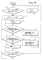
次に、パススイッチ13b2の動作モードについて説明する。パススイッチ13b2の動作モードは、図12のオペレーションBGの後に、テストアクセスの実施を示すテスト識別子をノード装置Bが試験対象回線で受信することにより、試験対象回線をTAP33b2へ接続し続ける固定モードへと変化する。図16は、パススイッチ13b2の制御処理の説明図である。別な実施の態様においては、下記のオペレーションDA~オペレーションDJの各オペレーションはステップであってもよい。
オペレーションDAにおいてスイッチ制御部63は、パススイッチ13b2を使用するテストアクセス回線の接続が行われたか否かを判定する。テストアクセス回線の接続が実行された場合(オペレーションDA:Y)、スイッチ制御部63は処理をオペレーションDCへ移行する。テストアクセス回線の接続が実行されていない場合(オペレーションDA:Y)、スイッチ制御部63は処理をオペレーションDBへ移行する。
オペレーションDBにおいてスイッチ制御部63は、パススイッチ13b2の状態が、テストアクセス用パススイッチとしてまだエントリしていない状態であると判定する。図17は、パススイッチ13b2の動作モードの状態遷移図である。図17において、状態120は、テストアクセス用パススイッチとしてまだエントリしていない状態を表す。図16を参照する。その後スイッチ制御部63は、処理をオペレーションDAへ戻す。
テストアクセス回線の接続が実行されると、スイッチ制御部63は、オペレーションDCにおいて、パススイッチ13b2の状態を、テストアクセス用パススイッチとしてエントリされテストアクセス実施を示す識別子の受信を待つモードへ移行する。この時点におけるパススイッチ13b2の状態を、図17において状態121より表す。
図16を参照する。オペレーションDDにおいてノード装置Bは、パススイッチ13b2へ入力される信号をE側及びW側の回線から受信する。オペレーションDEにおいてスイッチ制御部63は、E側の回線から受信したJ1バイトのみがテストアクセス実施を示す値「0x15」を有するか否かを判定する。E側の回線から受信したJ1バイトのみがテスト実施を示す値を有するとき(オペレーションDE:Y)、スイッチ制御部63は処理をオペレーションDFへ移行する。それ以外の場合(オペレーションDE:N)には、スイッチ制御部63は処理をオペレーションDGへ移行する。
オペレーションDFにおいてスイッチ制御部63は、パススイッチ13b2の動作モードを、E側からノード装置Bへ接続される回線をTAP33b2へ接続し続ける固定モードへ移行する。この時点におけるパススイッチ13b2の状態を、図17において状態122より表す。図16を参照する。その後スイッチ制御部63は、処理をオペレーションDJへ移行する。
オペレーションDGにおいてスイッチ制御部63は、W側の回線から受信したJ1バイトのみがテストアクセス実施を示す値「0x15」を有するか否かを判定する。W側の回線から受信したJ1バイトのみがテスト実施を示す値を有するとき(オペレーションDG:Y)、スイッチ制御部63は処理をオペレーションDHへ移行する。それ以外の場合(オペレーションDG:N)には、スイッチ制御部63は処理をオペレーションDIへ移行する。
オペレーションDHにおいてスイッチ制御部63は、パススイッチ13b2の動作モードを、W側からノード装置Bへ接続される回線をTAP33b2へ接続し続ける固定モードへ移行する。この時点におけるパススイッチ13b2の状態を、図17において状態122より表す。図16を参照する。その後スイッチ制御部63は、処理をオペレーションDJへ移行する。
オペレーションDIにおいてスイッチ制御部63は、パススイッチ13b2の動作モードを自動モードへ移行する。自動モードとは、E側及びW側から信号を入力する回線のうち、より回線品質がよい回線をパススイッチ13b2により自動的に選択するモードである。この時点におけるパススイッチ13b2の状態を、図17において状態121より表す。
図16を参照する。オペレーションDJにおいてスイッチ制御部63は、パススイッチ13b2を使用するテストアクセス回線の切断が行われたか否かを判定する。テストアクセス回線の切断が行われたとき(オペレーションDJ:Y)、スイッチ制御部63は、パススイッチ13b2の状態を、テストアクセス用パススイッチとしてまだエントリしていない状態へ移行し、処理をオペレーションDAへ戻す。この時点におけるパススイッチ13b2の状態を、図17において状態120より表す。図16を参照する。テストアクセス回線の切断が行われていないとき(オペレーションDJ:N)、スイッチ制御部63は、処理をオペレーションDDへ戻す。
図18は、上記の動作により遷移するパススイッチ13b2の動作モードの遷移条件を表すテーブルである。E側及びW側の両方の回線から、テストアクセスの実施を示すテスト識別子を受信したときは、パススイッチ13b2は自動モードで動作する。E側及びW側のどちらか一方の回線のみから、テストアクセスの実施を示すテスト識別子を受信したときは、パススイッチ13b2は、テストアクセスの実施を示すテスト識別子を受信した回線をTAP33b2へ接続し続ける固定モードで動作する。E側及びW側のどちらの回線からも、テストアクセスの実施を示すテスト識別子を受信しないときは、または上記以外の場合は、パススイッチ13b2は自動モードで動作する。
なお、本実施例においてテストアクセスの実施を示すテスト識別子を受信しない場合には、「テストアクセスの不実施」を表す識別子を受信する場合のほか、「テストアクセスの実施」及び「テストアクセスの不実施」のいずれも受信しない場合も含む。
テストアクセスの実施を示すテスト識別子は、テストアクセスを実施している間に継続して試験対象回線上で伝送されてもよい。または「テストアクセスの実施」を示すテスト識別子はテストアクセス開始時にのみ試験対象回線上で伝送され、「テストアクセスの不実施」を示すテスト識別子はテストアクセス終了時にのみ試験対象回線上で伝送されてもよい。
図19は、ノード装置Cにおけるテストアクセス回線の切断処理の説明図である。別な実施の態様においては、下記のオペレーションEA~オペレーションEEの各オペレーションはステップであってもよい。オペレーションEAにおいてコマンド処理部60は、制御端末16から送信されるテストアクセス回線切断コマンドを受信する。テストアクセス回線切断コマンドは、切断しようとするテストアクセス回線に使用されるTAPのTAP番号の指定を含む。
オペレーションEBにおいてコマンド処理部60は、指定されたTAP番号のTAPを用いたテストアクセスが、ノード装置Cで実施されているか否かを判定する。テストアクセスが実施されている場合(オペレーションEB:Y)、コマンド処理部60は処理をオペレーションECへ移行する。テストアクセスが実施されていない場合(オペレーションEB:N)、コマンド処理部60は処理を終了する。
オペレーションECにおいてコマンド処理部60は、試験対象回線を経由して送信する信号にテストアクセスの実施を示すテスト識別子を挿入することを停止するように、識別信号挿入部64に指示する。識別信号挿入部64は、コマンド処理部60からの指示に従って、テストアクセスの実施を示すテスト識別子の挿入を停止する。
オペレーションEDにおいてコマンド処理部60は、テストアクセス回線を切断するようにSTSSF制御部61に指示する。すなわちコマンド処理部60は、試験対象回線とTAP33cとを接続するクロスコネクト接続115を切断するように、STSSF制御部61に指示する。STSSF制御部61は、コマンド処理部60からの指示に従ってクロスコネクト接続115を切断する。
オペレーションEEにおいてコマンド処理部60は、試験対象回線と、ノード装置A側(W側)から信号を入力する運用回線とを接続するクロスコネクト接続110を再実施するように、STSSF制御部61に指示する。STSSF制御部61は、コマンド処理部60からの指示に従ってクロスコネクト接続110を再実施する。その後、コマンド処理部60は処理を終了する。
図20は、ノード装置CにおけるSTSSF23cの動作の説明図(その2)である。テストアクセス回線切断コマンドによって、試験対象回線と、ノード装置A側から信号を入力する運用回線とを接続するクロスコネクト接続110が再実施される。またテストアクセス回線切断コマンドによって、試験対象回線とTAP33cとを接続するクロスコネクト接続115が切断される。
図21は、ノード装置Bにおけるテストアクセス回線の切断処理の説明図である。別な実施の態様においては、下記のオペレーションFA~オペレーションFDの各オペレーションはステップであってもよい。
オペレーションFAにおいてコマンド処理部60は、制御端末16から送信されるテストアクセス回線切断コマンドを受信する。オペレーションFBにおいてコマンド処理部60は、指定されたTAP番号のTAPを用いたテストアクセスが、ノード装置Bで実施されているか否かを判定する。テストアクセスが実施されている場合(オペレーションFB:Y)、コマンド処理部60は処理をオペレーションFCへ移行する。テストアクセスが実施されていない場合(オペレーションFB:N)、コマンド処理部60は処理を終了する。
オペレーションFCにおいてコマンド処理部60は、テストアクセス回線を切断するようにSTSSF制御部61に指示する。すなわちコマンド処理部60は、テストアクセス用パススイッチ13b2と、試験対象回線及びこの回線と対をなしてUPSRによる多重化回線を形成する他方の回線と、を接続するクロスコネクト接続113及び114を切断するようにSTSSF制御部61に指示する。コマンド処理部60は、TAP33b2とテストアクセス用パススイッチ13b2とを接続するクロスコネクト接続を切断するようにSTSSF制御部61に指示する。STSSF制御部61は、コマンド処理部60からの指示に従ってこれらのクロスコネクト接続を切断する。
オペレーションFDにおいてコマンド処理部60は、運用回線で使用されるパススイッチ13b1と、試験対象回線及びこの回線と対をなしてUPSRによる多重化回線を形成する他方の回線とを接続するクロスコネクト接続102及び103を再実施するように、STSSF制御部61に指示する。コマンド処理部60は、運用回線用ポート33b1とパススイッチ13b1を接続するクロスコネクト接続を再実施するようにSTSSF制御部61に指示する。その後、コマンド処理部60は処理を終了する。
図22は、ノード装置BにおけるSTSSF23bの動作の説明図(その2)である。テストアクセス回線切断コマンドによって、運用回線用パススイッチ13b1に試験対象回線及びこれと対をなす回線とをそれぞれ接続するクロスコネクト接続102及び103が再実施される。またテストアクセス回線切断コマンドによって、試験対象回線及びこれと対をなす回線とテストアクセス用パススイッチ13b2とを接続するクロスコネクト接続113及び114が切断される。
テストアクセス回線切断コマンドによって、運用回線用パススイッチ13b1と運用回線用ポート33b1とを接続するクロスコネクト接続が再実施され、テストアクセス用パススイッチ13b2とTAP33b2とを接続するクロスコネクトが切断される。
図23は、TAP削除処理の説明図である。別な実施の態様においては、下記のオペレーションGA~オペレーションGCの各オペレーションはステップであってもよい。以下の説明ではノード装置CにおけるTAP削除処理の説明を行うが、ノード装置BにおけるTAP設削除処理も同様の処理である。
オペレーションGAにおいてコマンド処理部60は、制御端末16から送信されるTAP削除コマンドを受信する。TAP削除コマンドは、削除しようとするTAPを識別するために使用される「TAP番号」の指定を含む。
オペレーションGBにおいてコマンド処理部60は、TAP削除コマンドにより指定されたTAP番号のTAPについて記憶したエントリがあるか否かを判定する。エントリがある場合(オペレーションGB:Y)、コマンド処理部60は処理をオペレーションGCへ進める。エントリがない場合(オペレーションGB:N)、コマンド処理部60は処理を終了する。
オペレーションGCにおいてコマンド処理部60は、TAP削除コマンドにより指定されたTAP番号のエントリを、第1記憶部51から削除する。その後、コマンド処理部60は処理を終了する。
本実施例によれば、UPSR方式による多重化された伝送路を実現するネットワークにて回線試験を行う際に、多重化された回線のうち試験対象回線を特定し、試験対象回線をTAPへ接続するようにパススイッチを制御することができる。
また、本実施例によれば、回線試験を行う際に、PSW強制固定切替コマンドやPSW強制固定解除コマンドを与えることを試験実施者が意識する必要がなくなり、工数が低減される。
また、図5を参照して説明した実施例では、試験回線を伝送する信号のオーバヘッドへテスト識別子を含めた。これに代えて及び/又はこれに加えて、試験回線を伝送する信号のペイロードにテスト識別子を含めてもよい。このため、制御ユニット26に設けられた試験対象回線検出部65は、試験回線を伝送するフレームのペイロードに含まれたテスト識別子を検出するように構成されていてもよい。
ここに記載されている全ての例及び条件的な用語は、読者が、本発明と技術の進展のために発明者により与えられる概念とを理解する際の助けとなるように、教育的な目的を意図したものであり、具体的に記載されている上記の例及び条件、並びに本発明の優位性及び劣等性を示すことに関する本明細書における例の構成に限定されることなく解釈されるべきものである。本発明の実施例は詳細に説明されているが、本発明の精神及び範囲から外れることなく、様々な変更、置換及び修正をこれに加えることが可能であると解すべきである。
1 伝送装置
2 スイッチ
3、26 制御ユニット
4、62 試験対象判定部
5、63 スイッチ制御部
6、65 試験対象回線検出部
8、64 識別番号挿入部
10 リングネットワーク
20 ノード装置
13、13a、13b1、13b2 パススイッチ
2 スイッチ
3、26 制御ユニット
4、62 試験対象判定部
5、63 スイッチ制御部
6、65 試験対象回線検出部
8、64 識別番号挿入部
10 リングネットワーク
20 ノード装置
13、13a、13b1、13b2 パススイッチ
Claims (8)
- 1+1冗長構成を形成する2回線の間で使用回線を切り替えるスイッチを制御する制御ユニットであって、
前記2回線のどちらが回線試験の対象の回線であるかを判定する試験対象判定部と、
前記試験対象判定部により回線試験の対象と判定された回線を使用回線として選択するように、前記スイッチの選択状態を固定するスイッチ制御部と、
を備える制御ユニット。 - 前記試験対象判定部は、所定の識別信号が伝送される回線を回線試験の対象の回線として検出する試験対象回線検出部を備える請求項1に記載の制御ユニット。
- 回線試験の対象の回線上を伝送させる信号に前記所定の識別信号を挿入する識別信号挿入部をさらに備える請求項2に記載の制御ユニット。
- 前記所定の識別信号は、回線試験の対象の回線上を伝送する信号のオーバーヘッド部分に挿入される請求項2又は3に記載の制御ユニット。
- 前記所定の識別信号は、回線試験の対象の回線上を伝送する信号のペイロード部分に挿入される請求項2に記載の制御ユニット。
- 請求項1~5のいずれか一項に記載の制御ユニットと、
1+1冗長構成を形成する2回線の間で使用回線を切り替える前記スイッチと、を備え、
前記スイッチの選択状態が前記制御ユニットにより制御される伝送装置。 - 1+1冗長構成を形成する2回線の間で使用回線を切り替えるスイッチを制御するスイッチ制御方法であって、
前記2回線のどちらが回線試験の対象の回線であるかを判定し、
回線試験の対象と判定された前記回線を使用回線として選択するように、前記スイッチの選択状態を固定するスイッチ制御方法。 - 所定の識別信号が伝送される回線を回線試験の対象の回線として検出する請求項7に記載のスイッチ制御方法。
Priority Applications (1)
| Application Number | Priority Date | Filing Date | Title |
|---|---|---|---|
| PCT/JP2009/065441 WO2011027453A1 (ja) | 2009-09-03 | 2009-09-03 | 制御ユニット、伝送装置及びスイッチ制御方法 |
Applications Claiming Priority (1)
| Application Number | Priority Date | Filing Date | Title |
|---|---|---|---|
| PCT/JP2009/065441 WO2011027453A1 (ja) | 2009-09-03 | 2009-09-03 | 制御ユニット、伝送装置及びスイッチ制御方法 |
Publications (1)
| Publication Number | Publication Date |
|---|---|
| WO2011027453A1 true WO2011027453A1 (ja) | 2011-03-10 |
Family
ID=43649015
Family Applications (1)
| Application Number | Title | Priority Date | Filing Date |
|---|---|---|---|
| PCT/JP2009/065441 Ceased WO2011027453A1 (ja) | 2009-09-03 | 2009-09-03 | 制御ユニット、伝送装置及びスイッチ制御方法 |
Country Status (1)
| Country | Link |
|---|---|
| WO (1) | WO2011027453A1 (ja) |
Citations (2)
| Publication number | Priority date | Publication date | Assignee | Title |
|---|---|---|---|---|
| JPH0662008A (ja) * | 1992-05-29 | 1994-03-04 | Nec Corp | 遠隔試験方式 |
| JP2007243914A (ja) * | 2006-02-07 | 2007-09-20 | Nec Engineering Ltd | 回線試験機能を有する伝送装置 |
-
2009
- 2009-09-03 WO PCT/JP2009/065441 patent/WO2011027453A1/ja not_active Ceased
Patent Citations (2)
| Publication number | Priority date | Publication date | Assignee | Title |
|---|---|---|---|---|
| JPH0662008A (ja) * | 1992-05-29 | 1994-03-04 | Nec Corp | 遠隔試験方式 |
| JP2007243914A (ja) * | 2006-02-07 | 2007-09-20 | Nec Engineering Ltd | 回線試験機能を有する伝送装置 |
Similar Documents
| Publication | Publication Date | Title |
|---|---|---|
| EP0920153B1 (en) | Ring network for sharing protection resource by working communications paths | |
| US8090257B2 (en) | Optical communication system, optical communication apparatus, and method of monitoring fault alarm in path section detour | |
| JP4878479B2 (ja) | 光クロスコネクト装置 | |
| JPH0936824A (ja) | 光伝送システム及び伝送路切替制御方法 | |
| JPH11252016A (ja) | 光通信用ノード及びこれにより構成されるリング構成の波長分割多重光伝送装置 | |
| US8279762B2 (en) | Interface switching method and device | |
| JP2017005384A (ja) | 光ネットワークシステム、光伝送装置及び検出方法 | |
| JP5011257B2 (ja) | パストレース方法及びノード装置 | |
| CN115549775B (zh) | 光信号传输异常的处理方法、光传输设备及系统 | |
| JP2016086316A (ja) | 伝送装置および冗長提供方法 | |
| CN110113258B (zh) | 一种利用控制面链路自动保护数据面链路的方法和系统 | |
| JP2001186159A (ja) | リング伝送システム及びそのスケルチ方法 | |
| CN101589322A (zh) | 用于光网络的混合开关 | |
| JP2009246721A (ja) | マルチレイヤネットワークにおける、パス監視システム、パス管理装置、ノード装置、障害処理の抑止方法およびプログラム | |
| JP2001223728A (ja) | ネットワーク用伝送装置およびネットワーク伝送システム | |
| WO2011027453A1 (ja) | 制御ユニット、伝送装置及びスイッチ制御方法 | |
| WO2013061496A1 (ja) | 通信中継装置、稼働系切替方法及び通信中継制御基板 | |
| JP2007243508A (ja) | 光信号切替え装置および光信号切替え方法 | |
| JP6418958B2 (ja) | 子局装置、通信システム、及び故障特定方法 | |
| JP4869983B2 (ja) | 光伝送システムおよび光伝送装置 | |
| JP4485278B2 (ja) | 光伝送システム | |
| JP2016103689A (ja) | 光伝送システム、管理装置、光伝送ノード及び光伝送方法 | |
| JP3674541B2 (ja) | 光通信網における障害発生箇所の検出方法及び光通信システム | |
| CN209930282U (zh) | 一种利用控制面链路自动保护数据面链路的系统 | |
| JP5065832B2 (ja) | 光伝送システムおよびオペレーティング装置 |
Legal Events
| Date | Code | Title | Description |
|---|---|---|---|
| 121 | Ep: the epo has been informed by wipo that ep was designated in this application |
Ref document number: 09848984 Country of ref document: EP Kind code of ref document: A1 |
|
| NENP | Non-entry into the national phase |
Ref country code: DE |
|
| 122 | Ep: pct application non-entry in european phase |
Ref document number: 09848984 Country of ref document: EP Kind code of ref document: A1 |
|
| NENP | Non-entry into the national phase |
Ref country code: JP |