WO2011024463A1 - 液滴吐出装置およびその液滴吐出方法 - Google Patents
液滴吐出装置およびその液滴吐出方法 Download PDFInfo
- Publication number
- WO2011024463A1 WO2011024463A1 PCT/JP2010/005278 JP2010005278W WO2011024463A1 WO 2011024463 A1 WO2011024463 A1 WO 2011024463A1 JP 2010005278 W JP2010005278 W JP 2010005278W WO 2011024463 A1 WO2011024463 A1 WO 2011024463A1
- Authority
- WO
- WIPO (PCT)
- Prior art keywords
- holding table
- medium
- information
- holding
- droplet discharge
- Prior art date
- Legal status (The legal status is an assumption and is not a legal conclusion. Google has not performed a legal analysis and makes no representation as to the accuracy of the status listed.)
- Ceased
Links
Images





Classifications
-
- B—PERFORMING OPERATIONS; TRANSPORTING
- B41—PRINTING; LINING MACHINES; TYPEWRITERS; STAMPS
- B41J—TYPEWRITERS; SELECTIVE PRINTING MECHANISMS, i.e. MECHANISMS PRINTING OTHERWISE THAN FROM A FORME; CORRECTION OF TYPOGRAPHICAL ERRORS
- B41J3/00—Typewriters or selective printing or marking mechanisms characterised by the purpose for which they are constructed
- B41J3/407—Typewriters or selective printing or marking mechanisms characterised by the purpose for which they are constructed for marking on special material
- B41J3/4073—Printing on three-dimensional objects not being in sheet or web form, e.g. spherical or cubic objects
- B41J3/40731—Holders for objects, e. g. holders specially adapted to the shape of the object to be printed or adapted to hold several objects
-
- B—PERFORMING OPERATIONS; TRANSPORTING
- B05—SPRAYING OR ATOMISING IN GENERAL; APPLYING FLUENT MATERIALS TO SURFACES, IN GENERAL
- B05C—APPARATUS FOR APPLYING FLUENT MATERIALS TO SURFACES, IN GENERAL
- B05C13/00—Means for manipulating or holding work, e.g. for separate articles
-
- B—PERFORMING OPERATIONS; TRANSPORTING
- B05—SPRAYING OR ATOMISING IN GENERAL; APPLYING FLUENT MATERIALS TO SURFACES, IN GENERAL
- B05D—PROCESSES FOR APPLYING FLUENT MATERIALS TO SURFACES, IN GENERAL
- B05D1/00—Processes for applying liquids or other fluent materials
- B05D1/26—Processes for applying liquids or other fluent materials performed by applying the liquid or other fluent material from an outlet device in contact with, or almost in contact with, the surface
-
- B—PERFORMING OPERATIONS; TRANSPORTING
- B41—PRINTING; LINING MACHINES; TYPEWRITERS; STAMPS
- B41J—TYPEWRITERS; SELECTIVE PRINTING MECHANISMS, i.e. MECHANISMS PRINTING OTHERWISE THAN FROM A FORME; CORRECTION OF TYPOGRAPHICAL ERRORS
- B41J11/00—Devices or arrangements of selective printing mechanisms, e.g. ink-jet printers or thermal printers, for supporting or handling copy material in sheet or web form
- B41J11/008—Controlling printhead for accurately positioning print image on printing material, e.g. with the intention to control the width of margins
-
- B—PERFORMING OPERATIONS; TRANSPORTING
- B41—PRINTING; LINING MACHINES; TYPEWRITERS; STAMPS
- B41J—TYPEWRITERS; SELECTIVE PRINTING MECHANISMS, i.e. MECHANISMS PRINTING OTHERWISE THAN FROM A FORME; CORRECTION OF TYPOGRAPHICAL ERRORS
- B41J11/00—Devices or arrangements of selective printing mechanisms, e.g. ink-jet printers or thermal printers, for supporting or handling copy material in sheet or web form
- B41J11/0085—Using suction for maintaining printing material flat
-
- B—PERFORMING OPERATIONS; TRANSPORTING
- B41—PRINTING; LINING MACHINES; TYPEWRITERS; STAMPS
- B41J—TYPEWRITERS; SELECTIVE PRINTING MECHANISMS, i.e. MECHANISMS PRINTING OTHERWISE THAN FROM A FORME; CORRECTION OF TYPOGRAPHICAL ERRORS
- B41J11/00—Devices or arrangements of selective printing mechanisms, e.g. ink-jet printers or thermal printers, for supporting or handling copy material in sheet or web form
- B41J11/02—Platens
- B41J11/06—Flat page-size platens or smaller flat platens having a greater size than line-size platens
-
- B—PERFORMING OPERATIONS; TRANSPORTING
- B41—PRINTING; LINING MACHINES; TYPEWRITERS; STAMPS
- B41J—TYPEWRITERS; SELECTIVE PRINTING MECHANISMS, i.e. MECHANISMS PRINTING OTHERWISE THAN FROM A FORME; CORRECTION OF TYPOGRAPHICAL ERRORS
- B41J25/00—Actions or mechanisms not otherwise provided for
- B41J25/304—Bodily-movable mechanisms for print heads or carriages movable towards or from paper surface
- B41J25/308—Bodily-movable mechanisms for print heads or carriages movable towards or from paper surface with print gap adjustment mechanisms
-
- B—PERFORMING OPERATIONS; TRANSPORTING
- B41—PRINTING; LINING MACHINES; TYPEWRITERS; STAMPS
- B41J—TYPEWRITERS; SELECTIVE PRINTING MECHANISMS, i.e. MECHANISMS PRINTING OTHERWISE THAN FROM A FORME; CORRECTION OF TYPOGRAPHICAL ERRORS
- B41J29/00—Details of, or accessories for, typewriters or selective printing mechanisms not otherwise provided for
- B41J29/38—Drives, motors, controls or automatic cut-off devices for the entire printing mechanism
-
- B—PERFORMING OPERATIONS; TRANSPORTING
- B41—PRINTING; LINING MACHINES; TYPEWRITERS; STAMPS
- B41J—TYPEWRITERS; SELECTIVE PRINTING MECHANISMS, i.e. MECHANISMS PRINTING OTHERWISE THAN FROM A FORME; CORRECTION OF TYPOGRAPHICAL ERRORS
- B41J3/00—Typewriters or selective printing or marking mechanisms characterised by the purpose for which they are constructed
- B41J3/28—Typewriters or selective printing or marking mechanisms characterised by the purpose for which they are constructed for printing downwardly on flat surfaces, e.g. of books, drawings, boxes, envelopes, e.g. flat-bed ink-jet printers
-
- B—PERFORMING OPERATIONS; TRANSPORTING
- B41—PRINTING; LINING MACHINES; TYPEWRITERS; STAMPS
- B41J—TYPEWRITERS; SELECTIVE PRINTING MECHANISMS, i.e. MECHANISMS PRINTING OTHERWISE THAN FROM A FORME; CORRECTION OF TYPOGRAPHICAL ERRORS
- B41J3/00—Typewriters or selective printing or marking mechanisms characterised by the purpose for which they are constructed
- B41J3/407—Typewriters or selective printing or marking mechanisms characterised by the purpose for which they are constructed for marking on special material
- B41J3/4073—Printing on three-dimensional objects not being in sheet or web form, e.g. spherical or cubic objects
Definitions
- the present invention relates to a droplet discharge device that adheres to a medium by discharging droplets from droplet discharge means, and a droplet discharge method thereof.
- a device for manufacturing a color filter for a color liquid crystal panel or a printer head arranged so as to face the platen is moved left and right with respect to a medium supported by the platen.
- Ink jet printers (hereinafter referred to as printers) that eject ink and print on a medium are conventionally known.
- Patent Document 1 discloses a printer that performs printing on a medium placed on a platen by ejecting ink while moving a printer head along a guide rail.
- UV ink ultraviolet curable ink
- UV ink ultraviolet curable ink
- the operator needs to carefully place the jig in accordance with the reference position of the bed. For example, the jig is once placed on the bed, and the position of the jig is gradually shifted so as to coincide with the reference position, and finally coincide with the reference position. Therefore, extra work time is required for this placement work, and there is a problem that work efficiency is likely to be lowered.
- the placement work is performed manually by the operator, there is a problem that an attempt to improve the print quality by matching the reference position with higher accuracy leads to an increase in the work burden on the operator.
- printing is performed at a time while holding different media in different sizes and shapes on different jigs, there is also a problem that it is difficult to recognize the jig type and the position on the bed in correspondence. there were.
- the present invention has been made in view of such a problem, and improves the working efficiency and reduces the work burden on the operator, and the liquid drop ejecting apparatus capable of printing on various shapes of the medium, and the liquid drops thereof
- An object is to provide a discharge method.
- a droplet discharge device is a base member (for example, vacuum in the embodiment) that can support a holding table (for example, a jig in the embodiment) that holds the medium in a predetermined medium holding position.
- a table 13 droplet discharge means for discharging droplets (for example, the printer head 32 in the embodiment), and the medium held on the holding table in a state where the holding table is supported by the base member.
- a droplet discharge apparatus for example, a printer in the embodiment having a relative movement unit (for example, a left-right movement mechanism or a back-and-forth movement mechanism in the embodiment) that relatively moves the droplet discharge unit with respect to the medium.
- Holding table information for specifying the holding table (for example, barcodes 61, 61a, 352, 356, RFID tag, IC chip, magnetic field in the embodiment) Information that is stored or associated with the stripes and the heat-sensitive sheet), and holding position information acquisition means that acquires support position information related to the support position of the holding base in the base member (for example, the registration mark detection unit 34 in the embodiment, 134, bar code detectors 35 and 335, RFID reader, IC chip reader, magnetic head, CCD camera), information on the holding table specified by the holding table information acquired by the holding table information acquisition means, Based on the support position information acquired by the holding table information acquisition unit and information on a desired pattern, movement control of the droplet discharge unit by the relative movement unit and droplet discharge control from the droplet discharge unit are performed. In the desired pattern on the surface of the medium held at the predetermined medium holding position. Ejection control means for depositing the droplets (e.g., the controller 22 in the embodiment), characterized in that it comprises a.
- the droplet discharge device includes a base member capable of supporting a holding table for holding a medium at a predetermined medium holding position, droplet discharging means for discharging droplets, and the holding table supporting the base member.
- a liquid droplet ejection apparatus having relative movement means for moving the liquid droplet ejection means relative to the medium so as to face the medium held on the holding base in a state of being held
- Holding table information acquisition means for example, the embodiment
- holding table information acquisition means for example, information stored or linked to the barcode 61, 61a, 352, 356, RFID tag, IC chip, magnetic stripe, thermal sheet in the embodiment
- Bar code detectors 35, 335, RFID reader, IC chip reader, magnetic head, CCD camera and the holding table information acquisition means.
- the movement control of the droplet discharge unit by the relative movement unit and the discharge control of the droplet from the droplet discharge unit And a discharge control means for attaching droplets in the desired pattern to the surface of the medium held at the predetermined medium holding position.
- the droplet discharge device includes a base member capable of supporting a holding table for holding a medium at a predetermined medium holding position, droplet discharging means for discharging droplets, and the holding table supporting the base member.
- a liquid droplet ejection apparatus having relative movement means for moving the liquid droplet ejection means relative to the medium so as to face the medium held on the holding table in a state of being held
- Holding table information acquisition means for example, registration mark detectors 34 and 134 in the embodiment
- the movement control of the droplet discharge means by the relative movement means and the discharge control of the droplets from the droplet discharge means are performed, and the predetermined medium holding position is set.
- the base member is provided with positioning holding means (for example, a positioning member in the embodiment) for positioning and holding the holding table at a predetermined support position, and the holding table is positioned and held by the positioning holding means. It is preferable that the support position information is acquired based on the position of the holding table.
- positioning holding means for example, a positioning member in the embodiment
- a reference mark for example, the first registration mark 62a, the second registration mark 62b, the third registration mark 62c, and the fourth registration mark 64d in the embodiment
- the platform information acquisition means is configured to detect the reference mark and acquire the support position information.
- the holding table information includes at least one of information for specifying the type of the holding table, position information indicating a holding position of the medium on the holding table, medium arrangement information, quantity information, size information, and shape information. It is preferably included.
- the holding table has a hollow portion inside and is configured in a box shape, and the hollow portion is a suction unit (for example, capable of applying a negative pressure to the hollow portion)
- a suction hole that is connected to the supply / discharge blower 14) in the embodiment and communicates with the hollow portion is formed in a portion of the holding base that is out of the medium holding position, and the suction portion is provided with the hollow portion by the suction means. It is preferable to generate an air flow that flows toward
- the droplet discharge method includes a base member capable of supporting a holding table for holding a medium at a predetermined medium holding position, droplet discharging means for discharging a droplet, and the holding table supporting the base member.
- the droplet discharge method is performed using a droplet discharge device having a relative movement unit that moves the droplet discharge unit relative to the medium so as to face the medium held on the holding table.
- the holding table information for identifying the holding table is acquired, and the holding table information acquisition step for acquiring the support position information related to the support position of the holding table in the base member, and the holding table information acquisition step.
- the movement control of the droplet discharge means by the relative movement means and the discharge control of the droplets from the droplet discharge means are performed, and the desired surface is applied to the surface of the medium held at the predetermined medium holding position. And a discharge control step of attaching droplets in a pattern.
- the droplet discharge method includes a base member capable of supporting a holding table for holding a medium at a predetermined medium holding position, droplet discharging means for discharging a droplet, and the holding table supporting the base member.
- the droplet discharge method is performed using a droplet discharge device having a relative movement unit that moves the droplet discharge unit relative to the medium so as to face the medium held on the holding table.
- Holding table information acquisition step for acquiring holding table information for specifying the holding table, information on the holding table specified by the holding table information acquired by the holding table information acquisition step, and a desired pattern Based on the information regarding the movement of the droplet discharge means by the relative movement means and the discharge control of the droplets from the droplet discharge means, and held at the predetermined medium holding position. Characterized in that it comprises a discharge control step of depositing droplets at said desired pattern on the surface of the body.
- the droplet discharge method includes a base member capable of supporting a holding table for holding a medium at a predetermined medium holding position, droplet discharging means for discharging a droplet, and the holding table supporting the base member.
- the droplet discharge method is performed using a droplet discharge device having a relative movement unit that moves the droplet discharge unit relative to the medium so as to face the medium held on the holding table.
- the holding table information acquisition step for acquiring support position information related to the support position of the holding table in the base member, the support position information acquired by the holding table information acquisition step, and information on a desired pattern
- the surface of the medium held at the predetermined medium holding position by performing movement control of the droplet discharge means by the relative movement means and discharge control of the droplets from the droplet discharge means Characterized in that it comprises a discharge control step of depositing droplets at said desired pattern.
- the droplet discharge device includes holding table information acquisition means for acquiring holding table information and acquiring support position information of the holding table, and based on the information acquired by the holding table information acquisition means, The movement of the droplet discharge means and the discharge control of the droplets from the droplet discharge means are performed so that the droplets adhere to the surface of the medium in a desired pattern. Therefore, for example, image data can be generated based on holding table information including position information indicating a holding position, medium arrangement information, quantity information, size information, shape information, and the like, and support position information of the holding table. This enables printing on the medium held on the holding table. At this time, the working time can be shortened and the working efficiency can be improved as compared with the conventional case where the operator places the holding base so as to match the reference position of the base member.
- the droplet discharge apparatus includes holding table information acquisition means for acquiring holding table information, and based on the holding table information acquired by the holding table information acquisition means, movement control of the droplet discharge means and liquid It is configured to control the discharge of droplets from the droplet discharge means so that the droplets adhere to the surface of the medium in a desired pattern. Therefore, for example, by generating image data for printing based on the holding table information indicating what kind of medium is held on the holding table and how and in what arrangement, the medium held on the holding table Can be printed.
- the droplet discharge device includes holding table information acquisition means for acquiring support position information of the holding table, and movement of the droplet discharge means based on the support position information acquired by the holding table information acquisition means. It is configured so that droplets are attached in a desired pattern on the surface of the medium by performing control and droplet ejection control from the droplet ejection means. Therefore, it is possible to print on the medium held on the holding table by generating image data for printing based on the support position information on which position on the base member the holding table is placed. Become.
- the structure provided with the information reading means which reads the holding stand information provided in the holding stand is preferable. If comprised in this way, it will become possible to acquire correctly the holding stand information corresponding to a holding stand correctly.
- the base member is provided with positioning and holding means for positioning and holding the holding table at a predetermined support position.
- the position of the holding base in the base member is known in advance, it is easy to obtain the support position information.
- a reference mark for obtaining support position information is provided on the holding stand, and the support position information is obtained by detecting the reference mark.
- the image data is corrected based on the position of the reference mark, so that regardless of the position or the direction in which the holding table is placed with respect to the base member. Thus, it is possible to print on the medium held on the holding table.
- the holding table information includes at least one of information for specifying the type of holding table, position information indicating the holding position of the medium on the holding table, medium arrangement information, quantity information, size information, and shape information. It is preferable.
- the information for specifying the type of the holding table is included in the holding table information, for example, when performing printing by placing a plurality of types of holding tables on the base member simultaneously, the type of each holding table is accurately set. It becomes possible to grasp.
- the position information indicating the holding position of the medium is included in the holding table information, the position of the medium to be printed can be accurately detected.
- the holding table information includes medium arrangement information, image data for printing can be easily generated by arranging image data based on the arrangement information.
- the image data for printing can be easily generated by duplicating the image data based on the quantity information.
- the print target area can be accurately detected based on the size of the medium.
- the print target area (the shape of the print target area) can be accurately detected based on the shape of the medium.
- the suction means generate an air flow that flows toward the hollow portion in the suction hole.
- the mist droplets discharged from the droplet discharge means and floating in the vicinity of the holding table can be collected by being sucked into the hollow portion from the suction hole, so that the mist droplets are collected. It is possible to prevent adhesion to the medium or the droplet discharge means.
- the droplet discharge method includes a holding table information acquisition step of acquiring holding table information and acquiring support position information of the holding table, and a droplet based on the information acquired by the holding table information acquisition step.
- a droplet discharge method includes a holding table information acquisition step for acquiring holding table information, and movement control of the droplet discharge unit and the droplet discharge unit based on the information acquired by the holding table information acquisition step. And a discharge control step for controlling the discharge of the liquid droplets from the liquid droplets so that the droplets adhere to the surface of the medium in a desired pattern. Therefore, for example, by generating image data for printing based on the holding table information indicating what kind of medium is held on the holding table and how and in what arrangement, the medium held on the holding table Can be printed.
- the droplet discharge method includes a holding table information acquisition step for acquiring support position information of a holding table, and movement control of the droplet discharge means and liquid based on the information acquired by the holding table information acquisition step.
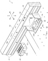
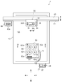
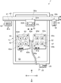
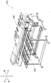
- FIG. 1 is a perspective view illustrating an appearance of a printer according to a first embodiment to which the present invention is applied. It is the perspective view which showed the guide rail vicinity of the said printer. It is a top view of the printer.
- FIG. 4 is a cross-sectional view showing a IV-IV portion in FIG. 3. It is the figure which showed the control system of the said printer. It is a flowchart when performing printing using the printer. It is a top view of the printer which concerns on Example 2 to which this invention is applied. It is a top view of the printer which concerns on Example 3 to which this invention is applied. It is a perspective view which shows a grid type printer. It is a top view of the printer which concerns on Example 4 to which this invention is applied.
- FIG. 1 is a perspective view of the printer 1
- FIG. 2 is a perspective view of a printing unit 30 to be described later
- FIG. 3 is a plan view of the printer 1
- FIG. 4 is a sectional view of a jig 50 to be described later
- FIG. 1 shows a control system diagram.
- the printer 1 mainly includes a support unit 2 provided at a lower portion and a printing unit 3 that can move back and forth above the support unit 2.
- the support unit 2 is mainly composed of a support leg 11, a table main body 12, a supply / discharge blower 14, and a control unit 20 that are horizontally supported by the support leg 11.
- a rectangular vacuum table 13 is provided at the center of the table body 12.
- a decompression chamber (not shown) is formed on the lower side (back side) of the vacuum table 13, and the surface of the vacuum table 13 and the decompression chamber communicate with each other by a plurality of supply / discharge holes 13a penetrating vertically. (See FIG. 2).
- the supply / discharge blower 14 is connected to a decompression chamber and an exhaust tube 71 described later, and is capable of sucking air and feeding air. By sucking air from the decompression chamber and sucking air from the supply / discharge hole 13a, the medium placed on the surface of the vacuum table 13 can be adsorbed to the vacuum table 13 and fixed.
- a control unit 20 is provided at the front end of the table body 12.
- the control unit 20 is mainly composed of an operation unit 21 including operation switches and display devices, and a built-in controller 22.
- the controller 22 is electrically connected to the operation unit 21 and receives an operation signal, and is electrically connected to each component described later, and outputs an operation signal to these components to perform operation control.
- the driving of a left-right moving mechanism, driving of a back-and-forth moving mechanism, driving of a supply / discharge blower 14, discharge of UV ink from a printer head 32 It is configured to control ultraviolet irradiation, ultraviolet irradiation from the right ultraviolet irradiation device 33R, and the like.
- the controller 22 receives a result of inspection light received by a registration mark detection unit 34 described later and information read by the barcode detection unit 35.
- the printing unit 3 includes a guide member 40 extending left and right above the table body 12, a maintenance device 42 built in the right end portion of the guide member 40, and a guide rail formed extending left and right on the front surface of the guide member 40.
- the printing unit 30 attached to 41 is mainly configured.
- FIG. 2 shows the printing unit 30 with the cover 39 removed.
- the printing unit 30 includes an integrated carriage 31, a printer head 32, a right ultraviolet irradiation device 33 ⁇ / b> R, a left ultraviolet irradiation device 33 ⁇ / b> L, a registration mark detection unit 34, and left and right of the printer head 32.
- the barcode detection unit 35 is mainly configured.
- the integrated carriage 31 is attached to the guide rail 41 so as to be movable to the left and right, and further includes a printer head 32, a right ultraviolet irradiation device 33R, a left ultraviolet irradiation device 33L, a registration mark detection unit 34, and a barcode detection unit 35. It is a mounting base.
- the printer head 32 is configured for each color, for example, magenta, yellow, cyan, and black, and a plurality of ejection nozzles (not shown) that eject UV ink downward are formed on the lower surface.
- Each of the right ultraviolet irradiation device 33R and the left ultraviolet irradiation device 33L has a built-in UV LED (not shown) capable of irradiating ultraviolet rays, and the ultraviolet rays from the UV LEDs are irradiated downward. Yes.
- the registration mark detection unit 34 includes a light emitting unit (not shown) and a light receiving unit (not shown) on its lower surface, and reflected light of inspection light emitted downward from the light emitting unit is received by the light receiving unit. It has a possible configuration.
- the inspection light intensity inspection light
- the portion where the first registration mark 62a to the fourth registration mark 62d are formed it is set so that the inspection light is not received (the inspection light with low intensity is received). Therefore, it is possible to detect whether or not the first registration mark 62a to the fourth registration mark 62d are positioned below the registration mark detection unit 34 based on the light reception result of the light receiving unit.
- the barcode detection unit 35 has a reading unit (not shown) formed on the lower surface thereof. By scanning above the barcode 61 described later, the reading unit reads the information of the barcode 61. Can be done.
- On the upper surface of the maintenance device 42 for example, four cap members 42a formed in the shape of the lower surface of the printer head 32 (surface on which the discharge nozzles are formed) are disposed. With this configuration, the print unit 30 is moved rightward so that the printer head 32 and the cap member 42a face each other in the vertical direction, and the cap member 42 is moved upward to cover the lower surface of the printer head 32, thereby The UV ink can be prevented from drying (thickening).
- the barcode 61 is read by the barcode detector 35 in the same manner as the registration mark detector 34, for example.
- the printing unit 30 is moved left and right along the guide rail 41 by a left and right moving mechanism (not shown). Further, the guide member 40 is slid back and forth by a front and rear movement mechanism (not shown) in a state where the printing unit 30 and the maintenance device 42 are mounted as described above. Note that various well-known techniques can be used as the left-right moving mechanism and the front-rear moving mechanism, and the description thereof is omitted in this specification.
- the medium when printing is performed on a flat medium, the medium may be placed directly on the vacuum table 13.
- the posture becomes unstable, so that it is difficult to ensure the positional accuracy with respect to the vacuum table 13. Therefore, by placing the jig 50 according to the present invention on the vacuum table 13 and placing the medium 8 on the jig 50, the jig can be held stably and the positional accuracy can be ensured.
- the configuration of the jig 50 will be described with reference to FIGS. 3 and 4.
- the jig 50 placed on the vacuum table 13 is fixed to the vacuum table 13 by the operation of the supply / discharge blower 14.
- the jig 50 is a box-shaped rectangular parallelepiped having a hollow portion 53 formed therein.
- the jig 50 for example, four accommodating recesses 55 capable of stably holding the medium 8 and a plurality of suction holes 52 communicating with the hollow portion 53 around the accommodating recess 55 are formed.
- An exhaust hole 54 communicating with the hollow portion 53 is formed in the left portion of the jig 50, and an exhaust tube 71 is connected to the exhaust hole 54.
- a filter 72 that allows air to pass and collects mist-like ink is disposed.
- a second reference mark as a reference mark that combines a cross shape and a circle so as to surround the receiving recess 55 and at a predetermined position relative to the receiving recess 55.
- a first registration mark 62a, a second registration mark 62b, a third registration mark 62c, and a fourth registration mark 62d are formed.
- a front end portion is formed with a barcode 61 as an identifier representing information on the jig 50.
- the bar code 61 includes, for example, the outer dimensions of the jig 50, the size and number of the receiving recesses 55, the number of registration marks (first registration mark 62a to fourth registration mark 62d), the positional relationship between registration marks, and the storage recess 55 with respect to the registration marks.
- a positional relationship, a registration mark corresponding to the origin among the plurality of registration marks (for example, the first registration mark 62a), a positional relationship of the registration marks corresponding to the origin with respect to the barcode 61, and the like are shown.
- the barcode 61 may be formed on the side surface of the jig 50, for example.
- the direction formed by the first registration mark 62a and the second registration mark 62b is the first axis, and the first registration mark 62a and the first registration mark 62a.
- step S101 shown in FIG. 6 the jig 50 is placed on the vacuum table 13 and fixed.
- the position of the medium 8 with respect to the vacuum table 13 can be accurately detected regardless of the mounting position and orientation of the jig 50 with respect to the vacuum table 13. Therefore, the operator can place the jig 50 on the vacuum table 13 without particularly considering the placement position and orientation.
- FIG. 3 illustrates the case where the jig 50 is placed on the rectangular vacuum table 13 so as to be parallel to the left and right front-rear direction, it is not always necessary to place the jig 50 in this manner.
- the medium 8 is accommodated in a state where the bottom surface is directed upward with respect to each accommodating recess 55.
- the jig 50 when placing the jig 50, it is preferable to place the jig 50 so as to be substantially parallel to the rectangular vacuum table 13 in the left-right front-rear direction.
- the movement of the printing unit 30 by the left and right movement mechanism and the movement of the guide member 40 by the front and rear movement mechanism are detected. It is possible to reduce the amount of time required for printing, and the work efficiency can be improved by shortening the time required for printing.
- step S102 an operation signal is output from the controller 22 to the left and right drive mechanism and the front and rear drive mechanism when the operator turns on a button (not shown) such as “position detection” of the operation unit 21, for example. .
- a button not shown
- the barcode detection unit 35 is scanned left and right and back and forth, and the barcode detection unit 35 is positioned above the barcode 61, information regarding the jig 50 represented in the barcode 61 is read, It is output to the controller 22.
- the bar code detector 35 may be positioned above the bar code 61 by manually operating the left / right drive mechanism and the front / rear drive mechanism.
- the vertical position of the printing unit 3 with respect to the support unit 2 is automatically adjusted according to the vertical height of the jig 50. preferable. If comprised in this way, it will become possible to print using the jig
- step S103 the controller 22 refers to the positional relationship of the first registration mark 62a (origin) with respect to the barcode 61 in the information input in step S102.
- an operation signal is output to the left / right drive mechanism and the front / rear drive mechanism so that the register mark detection unit 34 is positioned in the vicinity of the upper side of the first register mark 62a.
- the controller 22 After the position of the first registration mark 62a is detected, the controller 22 refers to the positional relationship of the second registration mark 62b with respect to the first registration mark 62a and positions the registration mark detection unit 34 in the vicinity above the second registration mark 62b. In this state, the position of the second registration mark 62b with respect to the vacuum table 13 is detected in the same manner as in the case of the first registration mark 62a. After detecting the position of the second registration mark 62b, the positions of the third registration mark 62c and the fourth registration mark 62d with respect to the vacuum table 13 are similarly detected.
- the controller 22 positions the first registration mark 62a to the fourth registration mark 62d with respect to the vacuum table 13 detected as described above, and the first registration mark 62a to the fourth registration mark 62d output from the barcode detection unit 35. Reference is made to the positional relationship of each housing recess 55. At this time, each position of the first registration mark 62a to the fourth registration mark 62d with respect to the vacuum table 13 detected in the above is made to correspond to each position of the first registration mark 62 output from the barcode detection unit 35, thereby obtaining a vacuum table. The position of each receiving recess 55 (medium 8) with respect to 13 can be calculated.
- the UV ink ejection control and the ultraviolet irradiation control are performed, so that the bottom surface of the medium 8 is controlled.
- the controller 22 recognizes whether the desired printing can be performed.
- the jig 50 is fixed in a slightly inclined state with respect to the vacuum table 13, the information displayed on the barcode 61 is read and the positions of the first registration mark 62a to the fourth registration mark 62d are read. By detecting this, the position of the medium 8 with respect to the vacuum table 13 can be detected with high accuracy. Therefore, the conventional alignment between the vacuum table 13 and the jig 50 is not required, the work burden on the operator can be reduced, and the work time can be shortened to improve the work efficiency.
- the controller 22 uses the position of each receiving recess 55 calculated as described above so that the printer head 32 faces the receiving recess 55 (the bottom surface of the medium 8).
- the printing unit 30 is moved in the left / right front / rear direction. Then, the control for moving the printing unit 30 left and right and back and forth, the control for discharging the UV ink from the printer head 32, and the control for irradiating ultraviolet rays from the right ultraviolet irradiation device 33R and the left ultraviolet irradiation device 33L are performed in combination. Thus, printing on the bottom surface of the medium 8 becomes possible.
- the ink droplet 32a having a relatively large diameter out of the UV ink ejected from the printer head 32 toward the medium 8 adheres to the medium 8 as shown in FIG. It is attached to the power position.
- the ink droplet 32 b having a relatively small diameter may become mist and cannot reach the medium 8 and may float between the printer head 32 and the medium 8.
- the floating ink droplets 32b adhere to, for example, the ejection nozzles of the printer head 32 and cause ejection failure, or adhere to a position different from the position where the medium 8 should be adhered, resulting in a decrease in print quality. May be invited.
- the distance between the printer head 32 and the medium 8 is set large, these problems tend to occur remarkably.
- the printer 1 is configured such that a plurality of suction holes 52 are formed in the upper portion of the jig 50 and the air in the hollow portion 53 is sucked by the supply / discharge blower 14. Yes.
- a negative pressure can be applied to the hollow portion 53 to generate an air flow toward the hollow portion 53 in the suction hole 52. Due to this air flow, the ink droplet 32 b floating between the printer head 32 and the medium 8 is sucked into the suction hole 52 and guided to the hollow portion 53 and is collected by the filter 72.
- the filter 72 As described above, by forcibly sucking the floating ink droplet 32b, it is possible to prevent the occurrence of ejection failure and the deterioration of print quality.
- the main effect achieved by the configuration of the first embodiment described above is the barcode formed on the jig 50 even when the jig 50 is placed at an arbitrary position on the vacuum table 13.
- the position of the medium 8 relative to the vacuum table 13 can be detected by reading the information 61 and detecting the first registration mark 62a to the fourth registration mark 62d. Therefore, by using the jig 50, for example, it is possible to print even on a solid medium 8 that is difficult to be placed directly on the vacuum table 13.
- the configuration of the printer 1 ′ according to the second embodiment to which the present invention is applied will be described with reference to FIG.
- the same members are denoted by the same reference numerals and description thereof will be omitted, and description will be made focusing on portions having different configurations.
- the printer 1 ′ has a working unit 30 a and a detection unit 30 b attached to a guide rail 41 formed on the front surface of the guide member 40, and is movable left and right.
- the work unit 30a is configured by mounting a printer head 32, a right ultraviolet ray irradiation device 33R, and a left ultraviolet ray irradiation device 33L on a work carriage 31a.
- the detection unit 30b is configured by mounting a registration mark detection unit 34 and a barcode detection unit 35 on a detection carriage 31b.
- FIG. 7 illustrates a case where the jig 50 and a jig 50a having a partially different configuration with respect to the jig 50 are placed on the vacuum table 13 and fixed.
- the jig 50a for example, four receiving recesses 57 are formed so that the bottom surface of the medium 9 having a truncated pyramid shape can be held upward.
- the barcode 61a shows, for example, the positional relationship of the storage recesses 57 with respect to the first registration mark 68a to the fourth registration mark 68d.
- the working unit 30a In the standby state before the start of printing, the working unit 30a is moved to the right and the lower surface of the printer head 32 is covered with the cap member.
- the detection unit 30 b On the other hand, the detection unit 30 b is moved to the left and is located at the left end of the guide rail 41.
- the detection unit 30b is scanned left and right and back and forth, and the information represented by the barcode 61 is read by the barcode detection unit 35.
- the registration mark detection unit 34 detects the positions of the first registration mark 62a to the fourth registration mark 62d, and when this detection is completed, the detection unit 30b is moved to the left and the left end of the guide rail 41 as in the standby state. It is supposed to be located in. Then, the controller 22 calculates the position of the medium 8 relative to the vacuum table 13 in the same manner as in the first embodiment, and prints on the bottom surface of the medium 8 using this calculation result.
- the information represented by the barcode 61a is read, the first registration mark 68a to the fourth registration mark 68d are detected, and the position of the medium 9 with respect to the vacuum table 13 is calculated in the same manner as described above. Are performed in order, and printing is performed on the bottom surface of the medium 9.
- the working unit 30a and the detecting unit 30b are configured separately.
- the detection unit 30b is positioned at the left end portion of the guide rail 41. Therefore, a mist-like ink droplet 32b adheres to the registration mark detection unit 34 and the barcode detection unit 35, and the light reception sensitivity of the inspection light in the registration mark detection unit 34 decreases, or the reading sensitivity in the barcode detection unit 35 decreases. It can be prevented from decreasing.
- the vacuum table 13 Even when a plurality of different types of jigs (for example, the jig 50 and the jig 50a) are placed on the vacuum table 13, the information of the jigs 50 and 50a is read from the barcodes 61 and 61a.
- the positions of the media 8 and 9 with respect to the vacuum table 13 can be accurately detected. Therefore, for example, it is possible to place four jigs of different types on the vacuum table 13 and perform printing simultaneously. Therefore, the trouble of placing the jig 50 on the vacuum table 13 and removing the jig 50 from the vacuum table 13 can be saved greatly, and the working time can be shortened and the working efficiency can be improved. Become.
- the case where the printing is performed on the bottom surface of the medium 9 after the printing on the bottom surface of the medium 8 is described as an example, but the bottom surface of the medium 8 and the bottom surface of the medium 9 are illustrated.
- the barcode 61 and the barcode 61a are continuously read, and the first registration mark 62a to the fourth registration mark 62d and the first registration mark 68a to the fourth registration mark 68d are continuously detected.
- the positions of the medium 8 and the medium 9 with respect to the vacuum table 13 are calculated, and printing is performed on the bottom surface of the medium 8 and the bottom surface of the medium 9 by using the calculation result.
- the configuration in the case where printing is performed on the bottom surface of the truncated cone-shaped medium 8 and the bottom surface of the quadrangular pyramid-shaped medium 9 is exemplified. It is possible to print on other media. For example, it is possible to print on a medium having various three-dimensional shapes by preparing a jig in which an accommodation recess that can hold the surface on which the printing is performed on the medium is directed upward.
- the configuration using the supply / discharge blower 14 is illustrated as a method of sucking and collecting the mist-like floating ink 32b in the jig, but is not limited to this configuration.
- a configuration in which an exhaust pump is built in the jig may be used. With this configuration, the exhaust tube 71 is not required, and the printer can be configured simply.
- the right ultraviolet irradiation device 33R and the left ultraviolet irradiation device 33L equipped with UVLEDs are illustrated as light sources for irradiating ultraviolet rays, but the light source is not limited to this UVLED.
- metal halide lamps that can irradiate ultraviolet rays, visible light LEDs, high-pressure mercury lamps, germicidal lamps, black lamps that can efficiently irradiate ultraviolet rays by eliminating visible light, and can irradiate ultraviolet rays in the wavelength range of about 280 to 315 nm
- a UV-B lamp a UV-C lamp capable of irradiating ultraviolet rays having a wavelength range of about 280 nm or less, and an electron beam irradiation apparatus may be used.
- a configuration in which physical property values (for example, strength, curing timing, etc.) of the UV ink to be used are linked to information described in the barcode is also possible.
- the jig 50 (50a) in which the four registration marks of the first registration mark 62a to the fourth registration mark 62d (first registration mark 68a to fourth registration mark 68d) are formed is illustrated.
- the present invention is not limited to this configuration. It suffices if the position of the register mark and the position of the housing recess are related to each other in the left-right front-rear direction plane. Therefore, it is sufficient that at least three register marks are formed on the jig 50 (50a) at different positions.
- first registration marks 62a to 62d first registration marks 68a to 68d
- first registration marks 68a to 68d the configuration in which four first registration marks 62a to 62d (first registration marks 68a to 68d) having a combination of a cross shape and a circular shape are formed.
- the registration mark detection unit 34 may detect the registration marks.
- the registration marks may be formed in an L shape, a circular shape, a triangular shape, or a combination thereof.
- the present invention has been described by exemplifying a configuration in which the present invention is applied to the printer 1 having a configuration in which the carriage is moved back and forth and left and right with respect to the vacuum table 13.
- the present invention is not limited to this configuration.
- the present invention can also be applied to a flat bed type printer that moves the vacuum table 13 back and forth and right and left with respect to a fixed carriage.
- the configuration in which the barcode detection unit 35 is mounted on the integrated carriage 31 (working carriage 31a) has been described as an example, but the present invention is not limited to this configuration.
- the operator may read the information by picking up the bar code detection unit 35 and holding it over the bar code 61 (bar code 61a).
- the configuration example in which various information related to the jig 50 (50a) is represented in the barcode 61 (one-dimensional code) has been described, but the configuration example is not limited thereto.
- a two-dimensional code having information in the horizontal direction and the vertical direction may be used.
- An RFID (Radio Frequency Identification) tag storing the above information is attached to the jig 50 (50a), information transmitted from the RFID tag is read by a reader (not shown), and the controller 22 receives the tag. It may be configured to output.
- a configuration in which a small semiconductor integrated circuit (IC chip) storing the above information is attached to the jig 50 (50a) is also possible.
- the configuration in which the information on the jig 50 (50a) is acquired by reading the information on the barcode 61 by the barcode detection unit 35 is illustrated, but the configuration is limited to this configuration.
- the information of the bar code 61 (for example, information on the jig 50 (50a), print image information, print position information, and the like represented by numbers and symbols) is displayed on the controller 22. It is configured to be automatically transmitted.
- the controller 22 creates print control information that defines the control content of each component based on the information from the barcode 61. By controlling each component according to this print control information, desired printing can be performed on the medium 8 (medium 9).
- the controller 22 is connected to a host computer (not shown) via an interface, and the detection result is transferred from the controller 22 to the host computer. The information may be generated and transferred to the controller 22 from the host computer. At this time, the controller 22 performs printing on the medium 8 by performing control based on the transferred information from the host computer.
- control information related to the UV ink ejection control and the ultraviolet irradiation control set in the controller 22 is, for example, only for the region surrounded by the first registration mark 62a to the fourth registration mark 62d. Alternatively, it may be the whole of the vacuum table 13 regardless of the size of the jig 50.
- the first register mark 62a to the fourth register mark 62d are detected and any one of them is set as the origin.
- a printer machine A configuration in which the position of the medium with respect to the vacuum table 13 is detected using the origin as the origin may be employed.
- control information related to UV ink ejection control and ultraviolet light irradiation control in the image of printing on the entire surface of the vacuum table 13 is generated in the host computer, and the printer 1 performs printing based on the mechanical origin.
- the tilt information of the jig 50 with respect to the vacuum table 13 obtained by detecting the first registration mark 62a to the fourth registration mark 62d is the rotation angle when correcting the image data of the medium and the medium Used for position grasp.
- the registration mark detection unit 34 and the barcode detection unit 35 are described as separate devices.
- the present invention is not limited to this.
- a configuration including a single detection unit may be used by using a barcode detection unit capable of detecting a registration mark or a registration mark detection unit capable of detecting a barcode.
- Example 2 it is set as the structure provided with the information (holding-base information in a claim) for specifying a jig
- the printer 100 does not include a barcode detection unit, and includes a registration mark detection unit 134 to form a printing unit 130. Further, the first register mark 62a to the fourth register mark 62d are formed on the jig 150, but the barcode for specifying the jig 150 is not formed. As shown in FIG. 8, when there is one type of jig (only the jig 150) placed on the vacuum table 13, it is not necessary to distinguish between the types of jigs. There is no need to form a code.
- an optical sensor that detects the positions of the first registration mark 62a to the fourth registration mark 62d based on a change in the received light intensity of the inspection light can be used.
- the vacuum table 13 is imaged from above, and the first registration mark 62a to the fourth registration mark 62d included in the image data obtained by the imaging are extracted, whereby the first in the vacuum table 13 is obtained. It is also possible to use a CCD camera that can detect the positions of the register marks 62a to 62d.
- the printer 100 configured in this way, for example, printing is performed according to the following printing procedure.
- the medium 8 is set on the jig 150, and the jig 150 is placed at an arbitrary position on the vacuum table 13.
- the center position of the first registration mark 62a to the fourth registration mark 62d is detected by the registration mark detection unit 134 while moving the printing unit 130 back and forth and right and left, and the detected first registration mark 62a to fourth registration mark 62d. Set one of the center positions to the origin.
- the skew (inclination) of the jig 150 with respect to the vacuum table 13 is detected, and the image data of the medium 8 is obtained according to the detected inclination.
- the image data correction may be performed by the controller 22 or by a host computer connected to the controller 22 via an interface.
- the printing unit 130 is once moved to the home position, the first registration mark 62a to the fourth registration mark 62d are detected again, and printing on the medium 8 is performed.
- a configuration in which a positioning member 161 for positioning 150 on the origin (machine origin) of the printer 100 and placing it on the vacuum table 13 may be provided in advance.
- the jig 150 is placed in alignment with the positioning member 161
- the range in which the first registration mark 62a to the fourth registration mark 62d can be detected is known in advance, so that the entire surface of the vacuum table 13 need not be scanned.
- the positioning member 161 is used, the inclination of the jig 150 obtained by detecting the first registration mark 62a to the fourth registration mark 62d is preferably used for correcting the inclination of the image data.
- a printing unit 220 on which a printer head (not shown) and a register mark detection unit (not shown) are mounted is attached to the guide rail 210 so as to be movable to the left and right. Further, a flat platen 230 is provided so as to be opposed to the printing unit 220 in the up and down direction.
- a clamp mechanism (not shown) for holding the medium, and conveyance for feeding the medium back and forth.
- a mechanism (not shown) and the like are provided.
- the jig 150 may not be placed on the platen 230.
- support bases 240 and 250 for holding the jig 150 substantially horizontally are arranged at the front and rear. Print. An example of the printing procedure in this case will be described. First, the medium 8 is set on the jig 150, and the jig 150 is placed on the platen 230. Next, the jig 150 is clamped using a clamp mechanism, and the jig 150 is set in a state where it can be fed back and forth with respect to the platen 230 by a transport mechanism.
- the printing unit 220 is moved left and right while feeding the jig 150 back and forth, and the center position of the first registration mark 62a to the fourth registration mark 62d is detected by the registration mark detection unit, and the detected first registration mark 62a is detected.
- the center position of any of the fourth registration marks 62d is set as the origin.
- the inclination of the jig 150 with respect to the front-rear direction is detected, and correction is performed to incline the image data according to the inclination.
- the correction for tilting the image data may be performed by the printer 200 or by a host computer connected to the printer 200 via an interface. Then, after the jig 150 is sent forward or backward to the origin position, the first registration mark 62a to the fourth registration mark 62d are detected again, and printing on the medium 8 is performed. After printing on the medium 8 is completed, the clamp by the clamp mechanism is released and the jig 150 is removed from the printer 200.
- the main effect achieved by the configuration of the third embodiment described above is that when the jig placed on the vacuum table 13 is known in advance (one kind of jig is used), the barcode Printing can be performed on a medium held by a jig while using a jig having a simple configuration that is not formed.
- Example 4 which is a configuration using a jig 351 in which a barcode 352 is formed but a registration mark is not formed will be described with reference to FIG.
- the same components as those in the first embodiment are denoted by the same reference numerals, and the description thereof will be omitted. The description will focus on configurations different from those in the first embodiment.
- the printer 300 includes a barcode detection unit 335 instead of the registration mark detection unit, and a printing unit 330 is configured.
- a bar code 352 on which information for specifying the jig 351 is described is formed on the jig 351, but a registration mark is not formed.
- a positioning member 361 for positioning and placing the jig 351 at the machine origin of the printer 300 is provided at the right front end of the vacuum table 13.
- the barcode detection unit 335 may be configured without being mounted on the integrated carriage 31.
- the barcode detection unit is separated from the integrated carriage 31 and in the vicinity of the predetermined position.
- a configuration in which 335 is fixed is also possible. In this case, in order to accurately read the information of the barcode 352, it is necessary to relatively move the barcode 352 and the barcode detection unit 335 by at least the length of the left and right of the barcode 352.
- the handy type barcode detection unit 335 may be connected to the controller 22 of the printer 300 through, for example, a USB connection, or connected to the host computer connected to the printer 300 through an interface through the USB connection. good.
- the host computer compares and refers to the jig identification information stored in the barcode 352 and the analysis table, so that the positional information of the media 353 and 354 held in the jig 351 (for example, the printing range) And the origin position).
- the origin when printing on the media 353 and 354, even when the machine origin of the printer 300 is used, the placement position of the jig 351 and the origin position set in the jig 351 are used in combination.
- the structure to do may be sufficient.
- a print pattern for coloring the background is possible.
- a solid print is applied to the entire print area of the medium 353, 354, and a character or a pattern is superimposed on the solid print portion. It is possible to print.
- the host computer by comparing and referring to the analysis table, the number of image data to be copied when generating image data with RIP (Raster Image Processor) is known in advance, so that the data processing burden is reduced.
- RIP Raster Image Processor
- the media 353 and 354 are set on the jig 351, and the jig 351 is positioned by the positioning member 361 and placed on the vacuum table 13.
- the barcode identification unit 335 identifies the jig related to the jig 351 stored in the barcode 352. Read information.
- the host computer that has received the jig identification information generates image data with reference to the analysis data associated with the jig identification information, and transmits the generated image data to the printer 300 (controller 22). After returning the printing unit 330 to the home position, the printer 300 performs printing on the media 353 and 354 in accordance with image data from the host computer.
- the printer 300 since the jig identification information stored in each barcode can be read using the barcode detection unit 335, a plurality of kinds of jigs 351 and 355 are provided as shown in FIG. It is placed on the vacuum table 13, and after reading the barcode 352 formed on the jig 351 and the barcode 356 formed on the jig 355, printing is performed collectively on the media 353, 354, 357. It can be carried out. Note that the jig 355 is positioned and placed at a predetermined position by the positioning member 362.
- the origin position is set in the same manner as when printing is performed on a general standard sheet.
- 10 illustrates the configuration in which the positioning member 361 is provided and the jig 351 is positioned and placed on the vacuum table 13, the configuration in which the jig 351 is positioned and placed on the vacuum table 13. Is not limited to this. That is, if the jig 351 can be positioned and placed on the vacuum table 13 by any method, it is not necessary to form a registration mark on the jig 351.
- the main effect achieved by the configuration of the fourth embodiment described above is that when a plurality of types of jigs holding media having different shapes are placed on the vacuum table 13 and printing is performed, registration marks are formed. It is possible to print on various shapes of media held by the jig while using the omitted simple jig.
- the jig identification information is formed on the jig in a format that can be detected by the registration mark detection unit (for example, a symbol format), and is linked to the jig identification information on the host computer. It is also possible to store an analysis table (medium arrangement, size, shape, etc. in the jig). In the case of this configuration, by reading the symbol formed on the jig with the registration mark detection unit, the arrangement, size, shape, etc. (hereinafter referred to as medium information) of the medium in the jig can be detected. Eliminating the need for information.
- medium information medium information
- an RFID tag can be used instead of the barcode.
- medium information stored so as to be rewritable using an RFID writer can be exchanged with the RFID reader via wireless communication.
- a passive type RFID tag for example, when a plurality of jigs are placed on the vacuum table 13, it communicates with the RFID tag attached to which jig. It becomes possible to grasp exactly.
- an IC chip in which medium information is stored so as to be rewritable can be used instead of the barcode.
- the interface that connects the IC chip reader that reads information stored in the IC chip may be either wired or wireless.
- a magnetic stripe in which medium information is stored so as to be rewritable can be used instead of the barcode.
- a magnetic head may be used as a reading device for reading information stored in the magnetic stripe.
- the above-described Examples 1, 2, and 4 it is also possible to use a heat-sensitive sheet on which medium information is printed so as to be rewritable instead of the barcode.
- the characters and symbols printed on the heat-sensitive sheet are imaged by, for example, a CCD camera and recognized, and the medium information can be grasped by comparing and referring to the recognized characters and symbols and the analysis table.
- tool is also possible, for example, it can engrave and form in a jig
- the storage means that can store rewritable medium information such as the above-mentioned RFID tag, IC chip, magnetic stripe, and thermal sheet is changed according to the medium (the shape, size, etc.) of the medium information. This is particularly effective when it is configured to rewrite items to be rewritten. In this configuration, the information to be rewritten does not depend on the type of jig.
- the case where the size of the printing area of the medium depends on the size of the recessed portion of the jig has been described.
- the shape of the jig and the printing of the medium are described.
- the relationship with the area is not limited to such a case. That is, there may be a configuration in which the shape and size of the printing area of the medium do not depend on the shape and size of the medium and the shape of the recessed portion of the jig.
- the configuration in which the medium is fitted and held in the concave portion of the jig has been described as an example.
- a convex portion is formed on the jig, and the convex portion A configuration in which the medium is held by fitting the medium may be used.
- a configuration may be adopted in which a fastener that can be engaged with the whole or a part of the medium is provided in the jig and the medium is held by the jig using the fastener.
- the medium 8 is firmly attached to the housing recess 55 using the negative pressure by the supply / discharge blower 14. You may comprise so that it may adsorb and fix.
- the configuration in which the jig 150 is positioned and placed on the right front end of the vacuum table 13 by providing the positioning member 161 on the vacuum table 13 has been described.
- a configuration may be adopted in which pins are arranged and fixed in a frame shape on the vacuum table 13, and a jig is positioned and placed so as to be fitted into a region surrounded by the pins.
- the right ultraviolet irradiation device 33R and the left ultraviolet irradiation device 33L that can irradiate ultraviolet rays are provided.
- the UV ink attached to the medium can be irradiated with ultraviolet rays by configuring as described above. It is possible to reliably cure by irradiating ultraviolet rays from the irradiation device. Therefore, it is possible to perform printing by attaching UV ink to a medium in which ink is difficult to penetrate.
- the printer head 32, the right ultraviolet irradiation device 33R, the left ultraviolet irradiation device 33L, the registration mark detection unit 34, and the barcode detection unit 35 are preferably mounted on the integrated carriage 31. If comprised in this way, compared with the case where said structural member is divided and mounted in two or more carriages, for example, while being able to reduce a number of parts, a control system can be comprised simply.
- the printer head 32, the right ultraviolet irradiation device 33R, and the left ultraviolet irradiation device 33L are mounted on the work carriage 31a, and the registration mark detection unit 34 and the barcode detection unit 35 are mounted on the detection carriage 31b.
- the configuration is also preferable. In such a configuration, for example, when the printer head 32, the right ultraviolet irradiation device 33R, and the left ultraviolet irradiation device 33L are operated and printing is performed on the medium, the detection carriage 31b is placed on the left and right ends of the guide rail. It becomes possible to evacuate.
- the present invention is limited to this configuration. It is not something.
- a barcode is formed on the jig as in the first to third embodiments, if the jig is placed straight back and forth with respect to the vacuum table 13, only one registration mark as the origin position is provided. The structure to form may be sufficient.
- the vacuum table 13 may be formed as a simple bone frame, and a jig for holding the medium in the bone frame may be supported in an exchangeable manner. Moreover, it may replace with the jig
- the jig when one type of jig is used and a positioning member is used (when the position of the medium in the jig is known in advance), for example, the jig is attached to the positioning member. It is preferable to provide a placement detection switch for detecting that the is set. Then, based on the detection signal from the placement detection switch, the position information can be acquired simply by reading the position of the medium in the jig, and there is no need to read the barcode formed on the jig.
- the position of the medium on the vacuum table can be determined by reading a barcode formed on each jig. It can be detected.
- the holding table information for specifying the type of jig is described as a character string, for example, at an easy-to-see position on each jig.
- a configuration in which the column is recognized and manually input to the printer may be used.
- the position of the registration mark is detected to detect the position of the jig on the vacuum table.
- the position can be detected.
- the position of the medium on the vacuum table can be detected by reading the barcode formed on each jig. Based on the detected position information, the medium position in the vacuum table can be detected.
- holding table information for specifying the type of jig is described as a character string in each jig, for example, and the operator recognizes the character string.
- a configuration in which manual input to the printer is possible is also possible.
- the position information necessary for printing on the medium by sucking and holding the jig holding the medium on the vacuum table 13 is large. There are two. That is, the position information of the jig in the vacuum table 13 (support position information in the claims) and the position information of the medium in the jig. When these two pieces of position information are detected, the position information of the medium in the vacuum table 13 can be detected based on these pieces of position information.
- USB for example, USB, RS-232C (Recommended standard-232c), wired and wireless LAN, infrared communication, Bluetooth (registered trademark), or the like is used as an interface for connecting the controller 22 and the host computer. It is possible. Similarly, the above-described interface can be used for the interface connecting the controller 22 (host computer) and each reader.
Landscapes
- Engineering & Computer Science (AREA)
- Manufacturing & Machinery (AREA)
- Ink Jet (AREA)
- Coating Apparatus (AREA)
Abstract
Description
8 媒体
13 バキュームテーブル(ベース部材)
14 給排ブロワー(吸引手段)
22 コントローラ(吐出制御手段)
32 プリンタヘッド(液滴吐出手段)
34 トンボ検出部(保持台情報取得手段)
35 バーコード検出部(保持台情報取得手段)
50 治具(保持台)
52 吸引孔
53 中空部
62a,62b,62c,62d 第1トンボ、第2トンボ、第3トンボ、第4トンボ(基準マーク)
161 位置決め部材(位置決め保持手段)
Claims (11)
- 媒体を所定の媒体保持位置に保持する保持台を支持可能なベース部材と、液滴を吐出する液滴吐出手段と、前記ベース部材に前記保持台が支持された状態で前記保持台に保持された媒体に対向させて前記液滴吐出手段を前記媒体に対して相対移動させる相対移動手段とを有する液滴吐出装置において、
前記保持台を特定するための保持台情報を取得するとともに、前記ベース部材における前記保持台の支持位置に関する支持位置情報を取得する保持台情報取得手段と、
前記保持台情報取得手段により取得された前記保持台情報により特定される前記保持台に関する情報、前記保持台情報取得手段により取得された前記支持位置情報および所望のパターンに関する情報に基づいて、前記相対移動手段による前記液滴吐出手段の移動制御および前記液滴吐出手段からの液滴の吐出制御を行って、前記所定の媒体保持位置に保持された媒体の表面に前記所望のパターンで液滴を付着させる吐出制御手段とを備えることを特徴とする液滴吐出装置。 - 媒体を所定の媒体保持位置に保持する保持台を支持可能なベース部材と、液滴を吐出する液滴吐出手段と、前記ベース部材に前記保持台が支持された状態で前記保持台に保持された媒体に対向させて前記液滴吐出手段を前記媒体に対して相対移動させる相対移動手段とを有する液滴吐出装置において、
前記保持台を特定するための保持台情報を取得する保持台情報取得手段と、
前記保持台情報取得手段により取得された前記保持台情報により特定される前記保持台に関する情報と所望のパターンに関する情報とに基づいて、前記相対移動手段による前記液滴吐出手段の移動制御および前記液滴吐出手段からの液滴の吐出制御を行って、前記所定の媒体保持位置に保持された媒体の表面に前記所望のパターンで液滴を付着させる吐出制御手段とを備えることを特徴とする液滴吐出装置。 - 媒体を所定の媒体保持位置に保持する保持台を支持可能なベース部材と、液滴を吐出する液滴吐出手段と、前記ベース部材に前記保持台が支持された状態で前記保持台に保持された媒体に対向させて前記液滴吐出手段を前記媒体に対して相対移動させる相対移動手段とを有する液滴吐出装置において、
前記ベース部材における前記保持台の支持位置に関する支持位置情報を取得する保持台情報取得手段と、
前記保持台情報取得手段により取得された前記支持位置情報と所望のパターンに関する情報とに基づいて、前記相対移動手段による前記液滴吐出手段の移動制御および前記液滴吐出手段からの液滴の吐出制御を行って、前記所定の媒体保持位置に保持された媒体の表面に前記所望のパターンで液滴を付着させる吐出制御手段とを備えることを特徴とする液滴吐出装置。 - さらに、前記保持台に設けられた前記保持台情報を読み取る情報読み取り手段を備えることを特徴とする請求項1または2に記載の液滴吐出装置。
- 前記ベース部材に前記保持台を所定支持位置に位置決め保持する位置決め保持手段が設けられており、
前記位置決め保持手段により前記保持台を位置決め保持した状態での前記保持台の位置に基づいて前記支持位置情報が取得されることを特徴とする請求項1または3に記載の液滴吐出装置。 - 前記保持台に、前記支持位置情報の取得のための基準マークが設けられており、
前記保持台情報取得手段が、前記基準マークを検出して前記支持位置情報を取得するように構成されていることを特徴とする請求項1または3に記載の液滴吐出装置。 - 前記保持台情報には、前記保持台の種類を特定するための情報、前記保持台における媒体の保持位置を示す位置情報、媒体の配置情報、数量情報、大きさ情報および形状情報の少なくとも1つが含まれていることを特徴とする請求項1、2および4のいずれかに記載の液滴吐出装置。
- 前記保持台は、内部に中空部を有して箱状に構成され、
前記中空部は、前記中空部に負圧を作用させることが可能な吸引手段と接続され、
前記保持台における前記媒体保持位置を外れた部分に、前記中空部と連通した吸引孔が形成され、
前記吸引手段により、前記吸引孔に前記中空部に向けて流れる空気流を発生させることを特徴とする請求項1~7のいずれかに記載の液滴吐出装置。 - 媒体を所定の媒体保持位置に保持する保持台を支持可能なベース部材と、液滴を吐出する液滴吐出手段と、前記ベース部材に前記保持台が支持された状態で前記保持台に保持された媒体に対向させて前記液滴吐出手段を前記媒体に対して相対移動させる相対移動手段とを有する液滴吐出装置を用いて行う液滴吐出方法であって、
前記保持台を特定するための保持台情報を取得するとともに、前記ベース部材における前記保持台の支持位置に関する支持位置情報を取得する保持台情報取得ステップと、
前記保持台情報取得ステップにより取得された前記保持台情報により特定される前記保持台に関する情報、前記保持台情報取得ステップにより取得された前記支持位置情報および所望のパターンに関する情報に基づいて、前記相対移動手段による前記液滴吐出手段の移動制御および前記液滴吐出手段からの液滴の吐出制御を行って、前記所定の媒体保持位置に保持された媒体の表面に前記所望のパターンで液滴を付着させる吐出制御ステップとを備えることを特徴とする液滴吐出方法。 - 媒体を所定の媒体保持位置に保持する保持台を支持可能なベース部材と、液滴を吐出する液滴吐出手段と、前記ベース部材に前記保持台が支持された状態で前記保持台に保持された媒体に対向させて前記液滴吐出手段を前記媒体に対して相対移動させる相対移動手段とを有する液滴吐出装置を用いて行う液滴吐出方法であって、
前記保持台を特定するための保持台情報を取得する保持台情報取得ステップと、
前記保持台情報取得ステップにより取得された前記保持台情報により特定される前記保持台に関する情報と所望のパターンに関する情報とに基づいて、前記相対移動手段による前記液滴吐出手段の移動制御および前記液滴吐出手段からの液滴の吐出制御を行って、前記所定の媒体保持位置に保持された媒体の表面に前記所望のパターンで液滴を付着させる吐出制御ステップとを備えることを特徴とする液滴吐出方法。 - 媒体を所定の媒体保持位置に保持する保持台を支持可能なベース部材と、液滴を吐出する液滴吐出手段と、前記ベース部材に前記保持台が支持された状態で前記保持台に保持された媒体に対向させて前記液滴吐出手段を前記媒体に対して相対移動させる相対移動手段とを有する液滴吐出装置を用いて行う液滴吐出方法であって、
前記ベース部材における前記保持台の支持位置に関する支持位置情報を取得する保持台情報取得ステップと、
前記保持台情報取得ステップにより取得された前記支持位置情報と所望のパターンに関する情報とに基づいて、前記相対移動手段による前記液滴吐出手段の移動制御および前記液滴吐出手段からの液滴の吐出制御を行って、前記所定の媒体保持位置に保持された媒体の表面に前記所望のパターンで液滴を付着させる吐出制御ステップとを備えることを特徴とする液滴吐出方法。
Priority Applications (5)
| Application Number | Priority Date | Filing Date | Title |
|---|---|---|---|
| KR1020127004365A KR101425467B1 (ko) | 2009-08-26 | 2010-08-26 | 액체방울 토출장치 및 그 액체방울 토출방법 |
| EP10811519.7A EP2471606B1 (en) | 2009-08-26 | 2010-08-26 | Droplet discharge device and droplet discharge method |
| CN201080037579.9A CN102481593B (zh) | 2009-08-26 | 2010-08-26 | 液滴喷出装置及其液滴喷出方法 |
| US13/391,821 US8702187B2 (en) | 2009-08-26 | 2010-08-26 | Droplet discharge device and droplet discharge method |
| JP2011528649A JP5480271B2 (ja) | 2009-08-26 | 2010-08-26 | 液滴吐出装置およびその液滴吐出方法 |
Applications Claiming Priority (2)
| Application Number | Priority Date | Filing Date | Title |
|---|---|---|---|
| PCT/JP2009/004122 WO2011024218A1 (ja) | 2009-08-26 | 2009-08-26 | プリンタ装置およびその印刷方法 |
| JPPCT/JP2009/004122 | 2009-08-26 |
Publications (1)
| Publication Number | Publication Date |
|---|---|
| WO2011024463A1 true WO2011024463A1 (ja) | 2011-03-03 |
Family
ID=43627349
Family Applications (2)
| Application Number | Title | Priority Date | Filing Date |
|---|---|---|---|
| PCT/JP2009/004122 Ceased WO2011024218A1 (ja) | 2009-08-26 | 2009-08-26 | プリンタ装置およびその印刷方法 |
| PCT/JP2010/005278 Ceased WO2011024463A1 (ja) | 2009-08-26 | 2010-08-26 | 液滴吐出装置およびその液滴吐出方法 |
Family Applications Before (1)
| Application Number | Title | Priority Date | Filing Date |
|---|---|---|---|
| PCT/JP2009/004122 Ceased WO2011024218A1 (ja) | 2009-08-26 | 2009-08-26 | プリンタ装置およびその印刷方法 |
Country Status (5)
| Country | Link |
|---|---|
| US (1) | US8702187B2 (ja) |
| EP (1) | EP2471606B1 (ja) |
| KR (1) | KR101425467B1 (ja) |
| CN (1) | CN102481593B (ja) |
| WO (2) | WO2011024218A1 (ja) |
Cited By (9)
| Publication number | Priority date | Publication date | Assignee | Title |
|---|---|---|---|---|
| JP2015058553A (ja) * | 2013-09-17 | 2015-03-30 | セーレン株式会社 | インクジェット記録装置 |
| JP2017177578A (ja) * | 2016-03-30 | 2017-10-05 | ローランドディー.ジー.株式会社 | プリンタおよび印刷用治具 |
| JP2018187873A (ja) * | 2017-05-10 | 2018-11-29 | セイコーエプソン株式会社 | 印刷装置、及び、制御方法 |
| JP2018197157A (ja) * | 2017-05-24 | 2018-12-13 | 理想科学工業株式会社 | 印刷装置 |
| JP2019010808A (ja) * | 2017-06-30 | 2019-01-24 | ローランドディー.ジー.株式会社 | 合成ファイル生成装置及びそれを備えた印刷システム、並びに合成ファイルを生成するためのコンピュータプログラム |
| JP2020006553A (ja) * | 2018-07-05 | 2020-01-16 | 株式会社ミマキエンジニアリング | 位置検出部の検出方法 |
| EP3711964A1 (en) * | 2019-03-19 | 2020-09-23 | Mimaki Engineering Co., Ltd. | Processing system |
| JP2021053998A (ja) * | 2019-09-30 | 2021-04-08 | セーレン株式会社 | インクジェット記録装置 |
| JP2021154283A (ja) * | 2017-08-22 | 2021-10-07 | 東芝テック株式会社 | 薬液滴下装置及び薬液吐出装置 |
Families Citing this family (17)
| Publication number | Priority date | Publication date | Assignee | Title |
|---|---|---|---|---|
| JP5626278B2 (ja) * | 2012-07-13 | 2014-11-19 | 株式会社村田製作所 | 基板へのインク塗布方法 |
| EP3129233B1 (en) * | 2014-04-11 | 2020-02-19 | OCE-Technologies B.V. | Flatbed printer assembly |
| EP3140019B1 (en) | 2014-05-09 | 2020-07-22 | Slab Dream Lab, Llc | Base plate for supporting interlocking building bricks |
| JP6354369B2 (ja) * | 2014-06-18 | 2018-07-11 | 富士ゼロックス株式会社 | 画像形成装置 |
| EP3159172B1 (en) * | 2015-10-23 | 2020-07-29 | Agfa Nv | Inkjet printing device with removable flat substrate support device |
| JP2017177424A (ja) * | 2016-03-29 | 2017-10-05 | セイコーエプソン株式会社 | 液滴吐出制御装置、液滴吐出制御方法および液滴吐出装置 |
| US10558192B2 (en) * | 2016-06-03 | 2020-02-11 | William Wilder | Movable gantry system configured to interface with jigs of different sizes |
| EP3272542B1 (en) * | 2016-07-19 | 2019-03-27 | OCE Holding B.V. | Method of printing on a three-dimensional object |
| US10328718B2 (en) * | 2017-04-03 | 2019-06-25 | Xerox Corporation | Printable merchandise holder for printing of contoured objects |
| US10308037B2 (en) | 2017-04-03 | 2019-06-04 | Xerox Corporation | Thermoformed customized object holder for direct to object printers |
| US10086625B1 (en) | 2017-04-03 | 2018-10-02 | Xerox Corporation | Integrated object packaging and holder for direct-to-object printer |
| JP6848663B2 (ja) | 2017-05-10 | 2021-03-24 | セイコーエプソン株式会社 | 印刷装置、及び、制御方法 |
| JP7019344B2 (ja) * | 2017-08-22 | 2022-02-15 | 東芝テック株式会社 | 薬液滴下装置及び薬液吐出装置 |
| JP7099233B2 (ja) * | 2018-09-28 | 2022-07-12 | ブラザー工業株式会社 | 接着装置 |
| US11135854B2 (en) * | 2018-12-06 | 2021-10-05 | Kateeva, Inc. | Ejection control using imager |
| JP6839227B2 (ja) | 2019-05-31 | 2021-03-03 | Dgshape株式会社 | 液滴付着装置 |
| JP7676891B2 (ja) * | 2021-04-05 | 2025-05-15 | セイコーエプソン株式会社 | 情報処理装置、情報処理方法、及び情報処理用プログラム |
Citations (6)
| Publication number | Priority date | Publication date | Assignee | Title |
|---|---|---|---|---|
| JPH0590799A (ja) * | 1991-09-30 | 1993-04-09 | Tdk Corp | プリント基板への接着剤付着方法及び装置 |
| JPH1027543A (ja) * | 1996-05-09 | 1998-01-27 | Fujitsu Ltd | プラズマディスプレイパネルの蛍光体層形成装置および形成方法 |
| JP2005045644A (ja) | 2003-07-24 | 2005-02-17 | Brother Ind Ltd | インクジェット記録装置 |
| JP2005283123A (ja) * | 2003-06-06 | 2005-10-13 | Shimadzu Corp | 液体分注装置 |
| JP2007203196A (ja) * | 2006-02-02 | 2007-08-16 | Musashi Eng Co Ltd | ワークを固定するパレットおよびそれを備える液体塗布装置 |
| JP2009179003A (ja) * | 2008-01-31 | 2009-08-13 | Mimaki Engineering Co Ltd | インクジェットプリンタ |
Family Cites Families (8)
| Publication number | Priority date | Publication date | Assignee | Title |
|---|---|---|---|---|
| CN1232839C (zh) * | 2001-09-28 | 2005-12-21 | 兄弟工业株式会社 | 液滴图案形成装置 |
| EP1548448A4 (en) * | 2002-09-27 | 2009-11-11 | Shimadzu Corp | FLUORITY SPORTS METHOD AND DEVICE |
| US7040748B2 (en) * | 2003-03-13 | 2006-05-09 | Brother Kogyo Kabushiki Kaisha | Inkjet printing apparatus |
| EP1972385B1 (en) * | 2005-12-28 | 2011-10-05 | Sharp Kabushiki Kaisha | Droplet applicator |
| JP4946194B2 (ja) * | 2006-06-16 | 2012-06-06 | ブラザー工業株式会社 | インクジェット記録装置 |
| DE102007036374A1 (de) * | 2007-07-31 | 2009-02-05 | Phoenix Contact Gmbh & Co. Kg | Markierobjekt und Markiervorrichtung |
| JP5181797B2 (ja) * | 2008-04-10 | 2013-04-10 | セイコーエプソン株式会社 | 画像形成装置 |
| JP4858567B2 (ja) * | 2009-03-31 | 2012-01-18 | ブラザー工業株式会社 | 液体吐出装置およびその制御方法 |
-
2009
- 2009-08-26 WO PCT/JP2009/004122 patent/WO2011024218A1/ja not_active Ceased
-
2010
- 2010-08-26 EP EP10811519.7A patent/EP2471606B1/en not_active Not-in-force
- 2010-08-26 CN CN201080037579.9A patent/CN102481593B/zh not_active Expired - Fee Related
- 2010-08-26 US US13/391,821 patent/US8702187B2/en active Active
- 2010-08-26 KR KR1020127004365A patent/KR101425467B1/ko not_active Expired - Fee Related
- 2010-08-26 WO PCT/JP2010/005278 patent/WO2011024463A1/ja not_active Ceased
Patent Citations (6)
| Publication number | Priority date | Publication date | Assignee | Title |
|---|---|---|---|---|
| JPH0590799A (ja) * | 1991-09-30 | 1993-04-09 | Tdk Corp | プリント基板への接着剤付着方法及び装置 |
| JPH1027543A (ja) * | 1996-05-09 | 1998-01-27 | Fujitsu Ltd | プラズマディスプレイパネルの蛍光体層形成装置および形成方法 |
| JP2005283123A (ja) * | 2003-06-06 | 2005-10-13 | Shimadzu Corp | 液体分注装置 |
| JP2005045644A (ja) | 2003-07-24 | 2005-02-17 | Brother Ind Ltd | インクジェット記録装置 |
| JP2007203196A (ja) * | 2006-02-02 | 2007-08-16 | Musashi Eng Co Ltd | ワークを固定するパレットおよびそれを備える液体塗布装置 |
| JP2009179003A (ja) * | 2008-01-31 | 2009-08-13 | Mimaki Engineering Co Ltd | インクジェットプリンタ |
Non-Patent Citations (1)
| Title |
|---|
| See also references of EP2471606A4 |
Cited By (15)
| Publication number | Priority date | Publication date | Assignee | Title |
|---|---|---|---|---|
| JP2015058553A (ja) * | 2013-09-17 | 2015-03-30 | セーレン株式会社 | インクジェット記録装置 |
| JP2017177578A (ja) * | 2016-03-30 | 2017-10-05 | ローランドディー.ジー.株式会社 | プリンタおよび印刷用治具 |
| JP2018187873A (ja) * | 2017-05-10 | 2018-11-29 | セイコーエプソン株式会社 | 印刷装置、及び、制御方法 |
| JP6999873B2 (ja) | 2017-05-10 | 2022-01-19 | セイコーエプソン株式会社 | 印刷装置、及び、制御方法 |
| JP2018197157A (ja) * | 2017-05-24 | 2018-12-13 | 理想科学工業株式会社 | 印刷装置 |
| JP2019010808A (ja) * | 2017-06-30 | 2019-01-24 | ローランドディー.ジー.株式会社 | 合成ファイル生成装置及びそれを備えた印刷システム、並びに合成ファイルを生成するためのコンピュータプログラム |
| US11511300B2 (en) | 2017-08-22 | 2022-11-29 | Toshiba Tec Kabushiki Kaisha | Chemical liquid dispensing apparatus and chemical liquid discharging device |
| JP2021154283A (ja) * | 2017-08-22 | 2021-10-07 | 東芝テック株式会社 | 薬液滴下装置及び薬液吐出装置 |
| JP7119176B2 (ja) | 2017-08-22 | 2022-08-16 | 東芝テック株式会社 | 薬液滴下装置及び薬液吐出装置 |
| JP7083283B2 (ja) | 2018-07-05 | 2022-06-10 | 株式会社ミマキエンジニアリング | 位置検出部の検出方法 |
| JP2020006553A (ja) * | 2018-07-05 | 2020-01-16 | 株式会社ミマキエンジニアリング | 位置検出部の検出方法 |
| EP3711964A1 (en) * | 2019-03-19 | 2020-09-23 | Mimaki Engineering Co., Ltd. | Processing system |
| US11214076B2 (en) | 2019-03-19 | 2022-01-04 | Mimaki Engineering Co., Ltd. | Processing system |
| JP2021053998A (ja) * | 2019-09-30 | 2021-04-08 | セーレン株式会社 | インクジェット記録装置 |
| JP7328860B2 (ja) | 2019-09-30 | 2023-08-17 | セーレン株式会社 | インクジェット記録装置 |
Also Published As
| Publication number | Publication date |
|---|---|
| KR101425467B1 (ko) | 2014-08-01 |
| US20120147074A1 (en) | 2012-06-14 |
| KR20120037494A (ko) | 2012-04-19 |
| US8702187B2 (en) | 2014-04-22 |
| EP2471606A4 (en) | 2013-08-07 |
| CN102481593A (zh) | 2012-05-30 |
| WO2011024218A1 (ja) | 2011-03-03 |
| CN102481593B (zh) | 2016-02-24 |
| EP2471606A1 (en) | 2012-07-04 |
| EP2471606B1 (en) | 2015-09-23 |
Similar Documents
| Publication | Publication Date | Title |
|---|---|---|
| KR101425467B1 (ko) | 액체방울 토출장치 및 그 액체방울 토출방법 | |
| US8083422B1 (en) | Handheld tattoo printer | |
| EP1503573B1 (en) | Calibration And Measurement Techniques For Printers | |
| ES2618301B1 (es) | Máquina y procedimiento de impresión digital sobre vidrio mono-pasada | |
| JP2009099939A (ja) | アライメントマーク形成装置 | |
| US8079765B1 (en) | Hand-propelled labeling printer | |
| CN115320270B (zh) | 一种玻璃激光自动打码方法 | |
| JP5516263B2 (ja) | 記録装置 | |
| KR101027568B1 (ko) | 얼라인먼트 마크 형성 장치 | |
| US9022519B2 (en) | Printing device | |
| US11225066B2 (en) | In-line detection and correction of underperforming light emitting diodes in a curing station of a three dimensional object printer | |
| JP5480271B2 (ja) | 液滴吐出装置およびその液滴吐出方法 | |
| CN114253086B (zh) | 描画系统 | |
| CN223520483U (zh) | 一种带车头视觉扫描的uv平板打印机 | |
| JP2023117848A (ja) | プリンタおよび画像の印刷方法 | |
| CN114074482A (zh) | 印刷装置、印刷控制方法以及记录介质 | |
| JP4697848B2 (ja) | インクジェットプリンタとそれを用いたプリント方法 | |
| JP2014060192A (ja) | パターン描画装置、パターン描画方法 | |
| JP2009179003A (ja) | インクジェットプリンタ | |
| JP2005138479A (ja) | インクジェットプリンタ | |
| JP5682400B2 (ja) | 印刷装置 | |
| JP5754181B2 (ja) | 印刷装置 | |
| JP6940332B2 (ja) | カッティング装置 | |
| US20250108462A1 (en) | Method for detecting a lens and/or nozzle on a focusing unit of a laser plotter for cutting, engraving, marking and/or labeling a workpiece, as well as a lens holder, a nozzle holder and a laser plotter for engraving, marking and/or labeling a workpiece therefor | |
| CN216635894U (zh) | 基于机器视觉定位的打印机 |
Legal Events
| Date | Code | Title | Description |
|---|---|---|---|
| WWE | Wipo information: entry into national phase |
Ref document number: 201080037579.9 Country of ref document: CN |
|
| 121 | Ep: the epo has been informed by wipo that ep was designated in this application |
Ref document number: 10811519 Country of ref document: EP Kind code of ref document: A1 |
|
| WWE | Wipo information: entry into national phase |
Ref document number: 2010811519 Country of ref document: EP |
|
| ENP | Entry into the national phase |
Ref document number: 20127004365 Country of ref document: KR Kind code of ref document: A |
|
| WWE | Wipo information: entry into national phase |
Ref document number: 13391821 Country of ref document: US |
|
| NENP | Non-entry into the national phase |
Ref country code: DE |
|
| WWE | Wipo information: entry into national phase |
Ref document number: 2011528649 Country of ref document: JP |