WO2011024409A1 - ドラム式洗濯機 - Google Patents
ドラム式洗濯機 Download PDFInfo
- Publication number
- WO2011024409A1 WO2011024409A1 PCT/JP2010/005097 JP2010005097W WO2011024409A1 WO 2011024409 A1 WO2011024409 A1 WO 2011024409A1 JP 2010005097 W JP2010005097 W JP 2010005097W WO 2011024409 A1 WO2011024409 A1 WO 2011024409A1
- Authority
- WO
- WIPO (PCT)
- Prior art keywords
- drum
- water
- washing machine
- type washing
- machine according
- Prior art date
Links
Images


Classifications
-
- D—TEXTILES; PAPER
- D06—TREATMENT OF TEXTILES OR THE LIKE; LAUNDERING; FLEXIBLE MATERIALS NOT OTHERWISE PROVIDED FOR
- D06F—LAUNDERING, DRYING, IRONING, PRESSING OR FOLDING TEXTILE ARTICLES
- D06F37/00—Details specific to washing machines covered by groups D06F21/00 - D06F25/00
- D06F37/02—Rotary receptacles, e.g. drums
- D06F37/04—Rotary receptacles, e.g. drums adapted for rotation or oscillation about a horizontal or inclined axis
-
- D—TEXTILES; PAPER
- D06—TREATMENT OF TEXTILES OR THE LIKE; LAUNDERING; FLEXIBLE MATERIALS NOT OTHERWISE PROVIDED FOR
- D06F—LAUNDERING, DRYING, IRONING, PRESSING OR FOLDING TEXTILE ARTICLES
- D06F39/00—Details of washing machines not specific to a single type of machines covered by groups D06F9/00 - D06F27/00
- D06F39/08—Liquid supply or discharge arrangements
- D06F39/083—Liquid discharge or recirculation arrangements
-
- D—TEXTILES; PAPER
- D06—TREATMENT OF TEXTILES OR THE LIKE; LAUNDERING; FLEXIBLE MATERIALS NOT OTHERWISE PROVIDED FOR
- D06F—LAUNDERING, DRYING, IRONING, PRESSING OR FOLDING TEXTILE ARTICLES
- D06F37/00—Details specific to washing machines covered by groups D06F21/00 - D06F25/00
- D06F37/26—Casings; Tubs
- D06F37/267—Tubs specially adapted for mounting thereto components or devices not provided for in preceding subgroups
Definitions
- the present invention relates to a drum-type washing machine having a rotating drum whose rotating shaft is inclined horizontally or downwardly toward the bottom.
- the drum-type washing machine circulates the washing water stored in the water tank using a circulation part equipped with a circulation pump.
- a circulation part equipped with a circulation pump.
- washing water is ejected from the nozzle of the circulation unit into the rotating drum.
- the nozzle is formed with a large number of jet outlets whose angles are gradually changed from the front surface of the rotating drum toward the center. That is, the washing water is ejected from a large number of ejection ports. Thereby, even when the amount of laundry such as clothes is large, cleaning is performed efficiently.
- the drum type washing machine described in Patent Document 2 includes a circulation pump having two pump discharge ports.
- the two pump discharge ports are switched according to the forward and reverse rotation directions of the circulating pump impeller.
- Circulation hoses are connected to the two pump discharge ports, respectively, and the ejection direction of the washing water into the rotating drum is switched. Thereby, the ejection direction of the washing water at the time of washing or rinsing can be changed according to the forward / reverse rotation of the rotating drum.
- washing water is ejected from a large number of ejection ports. For this reason, the usage-amount of washing water increases and it is difficult to perform water saving.
- washing water is applied to the laundry falling in the rotating drum, and the weight of the laundry into which the washing water has soaked increases.
- the laundry with increased weight falls off in the rotating drum. This improves the cleaning efficiency.
- This way of washing is called tapping.
- the drum-type washing machine described in Patent Document 2 when the amount of laundry is large, the weight of the laundry does not increase sufficiently, and the state of tapping is not achieved.
- the present invention efficiently supplies cleaning water to the laundry in the rotating drum when circulating the cleaning water in the aquarium.
- the present invention provides a drum type washing machine with high cleaning power.
- a drum-type washing machine is provided with a casing, a bottomed cylindrical water tank provided inside the casing and having a water tank opening, and a bottomed cylindrical water tank provided inside the water tank and having a drum opening.
- a rotating drum and a motor that is mounted on the outer bottom surface of the water tank and rotates the rotating drum with a rotating shaft inclined downward toward the horizontal or the bottom.
- the drum type washing machine according to the present invention is circulated by a circulation path that connects the bottom side of the water tank and the water tank opening side, and circulates wash water inside the water tank from the bottom side to the water tank opening side. And a plurality of jet outlets for jetting the wash water toward the inside of the rotating drum.
- the circulating cleaning water is ejected from the plurality of ejection ports into the rotary drum. Since the washing water is ejected from the plurality of outlets, the washing water is efficiently supplied to the laundry, and the washing power of the drum type washing machine is improved.
- FIG. 1 is a cross-sectional view of a drum-type washing machine according to Embodiment 1 of the present invention.
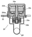
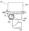
- FIG. 2A is a cross-sectional view of a circulation pump mounted on the drum type washing machine in the same embodiment.
- FIG. 2B is a side view of the circulation pump mounted on the drum type washing machine in the embodiment.
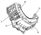
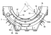
- FIG. 3A is a perspective view of a main part of a water tank of the drum type washing machine in the embodiment.
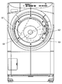
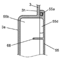
- FIG. 3B is a plan view of the front wall of the water tank of the drum type washing machine according to the embodiment as viewed from the inside.
- FIG. 4 is a cross-sectional view of the vicinity of the water conduit in the circulation path of the drum type washing machine in the same embodiment.
- FIG. 5A is a cross-sectional view of the vicinity of the discharge port of the circulation path of the drum type washing machine in the same embodiment.
- FIG. 5B is a cross-sectional view of the vicinity of another discharge port of the circulation path of the drum type washing machine in the embodiment.
- FIG. 6 is an explanatory view showing a state of ejection of the washing water of the drum type washing machine in the same embodiment.
- FIG. 7A is a cross-sectional view of the vicinity of the discharge port of the circulation path of the drum type washing machine according to Embodiment 2 of the present invention.
- FIG. 7B is a cross-sectional view of the vicinity of another discharge port of the circulation path of the drum type washing machine in the embodiment.
- FIG. 8 is a cross-sectional view of the discharge port of the circulation path of the drum type washing machine in the third embodiment of the present invention.
- FIG. 9 is a cross-sectional view of the outlet of the circulation path of the drum type washing machine in the fourth embodiment of the present invention.
- FIG. 10A is a cross-sectional view of the jet outlet of the circulation path of the drum type washing machine in the fifth embodiment of the present invention.
- FIG. 10B is a cross-sectional view of another outlet of the circulation path of the drum type washing machine in the embodiment.
- FIG. 11 is a cross-sectional view of the outlet of the circulation path of the drum type washing machine in the sixth embodiment of the present invention.
- FIG. 12 is a cross-sectional view of the vicinity of the discharge port of the circulation path of the drum type washing machine in the seventh embodiment of the present invention.
- FIG. 13 is the top view which looked at the front wall of the water tank of the drum type washing machine in Embodiment 8 of this invention from the inside.
- FIG. 14A is a cross-sectional view of the vicinity of the discharge port of the circulation path of the drum type washing machine in the same embodiment.
- FIG. 14B is a cross-sectional view of the vicinity of another discharge port of the circulation path of the drum type washing machine in the embodiment.
- FIG. 15A is a plan view of a front wall of another water tank of the drum type washing machine according to the embodiment as viewed from the inside.
- FIG. 15B is a plan view of a front wall of still another water tank of the drum type washing machine according to the embodiment as viewed from the inside.
- FIG. 16A is a cross-sectional view of the vicinity of still another discharge port of the circulation path of the drum type washing machine in the embodiment.
- 16B is a partial cross-sectional view taken along line 16B-16B in FIG. 16A.
- FIG. 1 is a cross-sectional view of a drum-type washing machine according to Embodiment 1 of the present invention.
- FIG. 2A is a cross-sectional view of a circulation pump mounted on the drum type washing machine in the same embodiment.
- FIG. 2B is a side view of the circulation pump mounted on the drum type washing machine in the embodiment.
- the drum type washing machine 1 of the present embodiment has a water tank 3, a water supply unit 7, a drainage unit 8, and a circulation path 16 in a housing 2.
- a rotating drum 4 is provided inside the water tank 3. Both the water tank 3 and the rotating drum 4 have a bottomed cylindrical shape.
- the rotating drum 4 is rotated by a motor 6 mounted on the outer bottom surface 30 of the water tank 3.
- the motor 6 rotates in both clockwise and counterclockwise directions. That is, the motor 6 can rotate forward and backward. With these configurations, a washing step, a rinsing step, and a dewatering step are performed.
- the drum type washing machine 1 includes a drying unit 9 as necessary to perform a drying step.
- the circulation path 16 is provided by communicating the bottom side of the water tank 3 and the water tank opening 13 side described later.
- the washing water stored in the water tank 3 is circulated from the bottom side of the water tank 3 to the water tank opening 13 side by the circulation path 16.
- the detergent dissolves quickly in the wash water, or the deviation of the detergent in the wash water is prevented.
- the water supply unit 7 is connected to the water supply, and supplies water to the water tank 3 by opening a water supply valve (not shown).
- a detergent container (not shown) is provided inside the water supply unit 7.
- the water supplied from the water supply enters the aquarium 3 as washing water while dissolving the detergent in the detergent container.
- the drainage unit 8 drains the wash water out of the housing 2 by opening the drain valve 19 at the end of the washing step or at the end of the rinsing step.
- the circulation path 16 repeatedly uses the circulation pump 20 to suck the wash water stored in the water tank 3 from the bottom side of the water tank 3, send it to the water tank opening 13 side, and return it to the water tank 3 again.
- the drum-type washing machine 1 has an operation panel 21 at the upper front of the housing 2.
- the operation start instruction reaches the control unit 22.
- the control unit 22 displays that the operation has been started on a display unit (not shown) of the operation panel 21, closes the drain valve 19, opens the water supply valve, and starts water supply. Thereafter, the control unit 22 performs various operations such as washing, rinsing, dehydration, and drying.
- a main body opening 2 b is formed in the front surface of the housing 2 and is opened and closed by the door 5.
- a drum opening 54 is formed on the front surface of the rotating drum 4.
- a water tank opening 13 is formed in front of the water tank 3.
- the front of the rotating drum 4 and the water tank 3 refers to the surface facing each bottom.
- the laundry is put in and out of the rotary drum 4 through the main body opening 2b, the water tank opening 13 and the drum opening 54.
- An annular sealing material 14 is attached between the main body opening 2 b and the water tank opening 13 of the water tank 3. This prevents the washing water from jumping out of the water tank 3 when the door 5 is closed.
- the motor 6 has a forward / reverse partial rotation drive mode and a forward / reverse continuous rotation drive mode, and drives the rotary drum 4.
- the forward / reverse partial rotation drive mode is a drive mode in which the rotating drum 4 repeats a rapid partial rotation exceeding 90 degrees and less than 180 degrees in the forward direction and the reverse direction.
- the forward / reverse continuous rotation drive mode is a drive mode in which the rotary drum 4 continuously rotates and repeats forward rotation and reverse rotation alternately.
- the forward / reverse continuous rotation drive mode the laundry lifted by the rotation of the rotating drum 4 falls by its own weight and repeats the behavior of being lifted by the rotation of the rotating drum 4 again.
- the forward / reverse partial rotation drive mode and the forward / reverse continuous rotation drive mode are executed alternately.
- the laundry In the forward / reverse partial rotation drive mode, the laundry is lifted to more than 90 degrees and less than 180 degrees, and then peeled off from the inner surface of the rotating drum 4 due to inertial force or its own weight. Laundry is swollen and loosened by including washing water, and is easy to slip, so that it is loosened when dropped. Moreover, the washing
- the forward / reverse partial rotation drive mode in the forward / reverse partial rotation drive mode, the upper and lower positions of a plurality of laundry are hardly changed. Further, since the laundry at the bottom of the rotating drum 4 is difficult to move, uneven washing is likely to occur. Therefore, by using the forward / reverse continuous rotation drive mode, the vertical position of the laundry including the laundry at the bottom of the rotating drum 4 is switched. As described above, the forward / reverse partial rotation drive mode prevents the laundry from being entangled, twisted, and wrinkled, and the forward / reverse continuous rotation drive mode greatly changes the vertical position of the laundry to perform uniform washing.
- the circulation pump 20 is provided in the middle of the circulation path 16.
- the circulation pump 20 is fixed to the base plate 2 a of the housing 2.
- a discharge side path 16 b of the circulation path 16 is connected to the downstream side of the circulation pump 20.
- the circulation pump 20 has a resin-made pump casing 20b that houses the impeller 20a, and a motor casing 20d that houses the circulation motor 20c.
- the impeller 20a and the circulation motor 20c are connected by a motor shaft 20e.
- the pump casing 20b and the motor casing 20d are positioned and integrated by the bearing partition 20da on the opening side of the pump casing 20b.
- the circulation pump 20 is fixed to the base plate 2a by a resin mounting seat 35. As the circulation motor 20c rotates, the impeller 20a rotates through the motor shaft 20e. Washing water is sent from the circulation pump suction port 20f to the circulation pump discharge port 20g by the rotation of the impeller 20a.
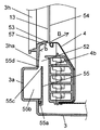
- FIG. 3A is a perspective view of a main part of a water tank of the drum type washing machine in the same embodiment.
- FIG. 3B is a plan view of the front wall of the water tank of the drum type washing machine according to the embodiment as viewed from the inside.
- FIG. 4 is a cross-sectional view of the vicinity of the water conduit in the circulation path of the drum type washing machine in the same embodiment.
- a substantially Y-shaped bulging portion 3 a bulging forward (upper right direction in FIG. 3A) is formed in the lower half of the front wall 3 h of the water tank 3.
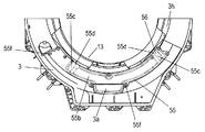
- a cover 55 whose outer shape is substantially the same as that of the bulging portion 3a is attached to the bulging portion 3a from the inside of the water tank 3 using screws 55f. Moreover, as shown in FIG. 4, the cover 55 is attached by the bulging part 3a via the packing 55a, and forms the water conduit 55b.
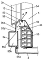
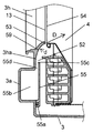
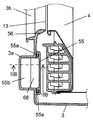
- FIG. 5A is a cross-sectional view of the vicinity of the discharge port of the circulation path of the drum-type washing machine in the same embodiment.
- FIG. 5B is a cross-sectional view of the vicinity of another discharge port of the circulation path of the drum type washing machine in the embodiment.
- One end of a connecting portion 51 extending in the lateral direction is connected to the lower end of the bulging portion 3a.
- the other end of the connecting portion 51 is connected to the discharge side path 16 b of the circulation path 16.
- notches 55 c are formed at the upper left and right ends of the cover 55.
- the cutout portion 55c is cut out of the cover 55 and the sealing structure of the packing 55a.
- a discharge port 55d having an opening is formed.
- the back surface of the front wall 3h of the water tank 3 is a surface that can be seen when the water tank 3 is viewed from the inside, that is, a surface facing the inside of the water tank 3.
- the washing water sent by the circulation pump 20 flows into the water conduit 55b from the connecting portion 51 through the discharge side passage 16b of the circulation passage 16.
- the washing water that has flowed into the water conduit 55b is discharged from the back surface of the front wall 3h of the water tank 3 and the surface of the front wall 4b of the rotary drum 4 that is the surface facing the back surface of the front wall 3h. It is discharged from 55d.
- the wash water discharged from the water conduit 55b through the discharge port 55d is jetted from the annular jet port 53 to the inside of the rotary drum 4 through the flow channel 52.
- a plurality of discharge ports 55d are provided in the rotational direction of the rotary drum 4 so as to face the annular ejection port 53.
- the front wall 3h of the water tank 3 has an inclined surface 3ha and a guide surface 56 following the inclined surface 3ha from a position corresponding to the discharge port 55d.
- the washing water discharged from the discharge port 55d to the flow path 52 flows along the guide surface 56 from the inclined surface 3ha. Accordingly, the wash water is ejected from the ejection port 53 through the drum opening 54 toward the back of the rotating drum 4 as indicated by an arrow A in FIG. 5A. Since the washing water reaches the back of the rotating drum 4, the washing water is supplied to the laundry more efficiently.
- the cleaning water can be ejected at a different angle.
- the inclination angle of the guide surface 56 corresponding to the discharge port 55d on the left side (right side in FIG. 3B) when viewed from the front of the branched water conduit 55b is a (see FIG. 5A), and is also viewed from the front of the water conduit 55b.
- the inclination angle of the guide surface 57 corresponding to the right discharge port 55d (left side in FIG. 3B) is b (see FIG. 5B).
- the guide surface 56 and the guide surface 57 are formed so that the inclination angle is a> b.
- FIG. 6 is an explanatory view showing a state of the washing water jet of the drum type washing machine in the same embodiment.
- the washing water ejected from the left outlet 53 as viewed from the front of the drum type washing machine 1 (that is, the washing water ejected in the direction indicated by the arrow A in FIG. 5A) is upward as shown in the shower shape S1 in FIG. To erupt.
- the shower shape S2 of FIG. 6 the washing water from the right outlet 53 when viewed from the front of the drum-type washing machine 1 (that is, the washing water ejected in the direction indicated by the arrow B in FIG. 5B), It ejects downward from the shower shape S1.
- the cleaning water discharged from each discharge port 55d flows along the guide surface 56 or the guide surface 57 having different inclination angles. Thereafter, since the washing water is ejected from the ejection port 53 through the drum opening 54 into the rotary drum 4, the washing water is ejected as washing water having different ejection angles.
- the inclination angle of the guide surface 56 or the guide surface 57 affects the spreading state of the washing water after the ejection.
- the inclination angle is small (that is, in the case of the guide surface 57 having the inclination angle b in the present embodiment)
- the angle of the cleaning water flowing along the inclined surface 3ha is rapidly changed by the guide surface 57.
- the cleaning water collides with the guide surface 57.
- the washing water extends along the guide surface 57 and by collision.
- the tilt angle is large (that is, in the case of the guide surface 56 with the tilt angle a in the present embodiment)
- the wash water flowing along the tilted surface 3ha flows along the guide surface 56 as it is, It erupts without spreading much.
- the shower shape S2 of the wash water ejected from the right jet port 53 with a small tilt angle is compared to the shower shape S1 of the wash water jetted from the left jet port 53 with a large tilt angle.
- the laundry does not contain washing water and becomes bulky with a large volume.
- the washing water is jetted from the right jet port 53 to the rotary drum 4. Since the washing water is greatly expanded and ejected from the right jet 53, the laundry near the left jet 53 can be wetted quickly.
- the laundry containing the washing water has a reduced volume, and thus the blockage of the left jet port 53 is eliminated.
- the washing water ejected from the right ejection port 53 has a large spread, and thus it is difficult to reach the back of the rotating drum 4.
- the washing water ejected from the left ejection port 53 has a small spread and reaches the back toward the center of the rotating drum 4.
- the laundry in the back of the rotating drum 4 can be wetted quickly.
- the laundry in the rotating drum 4 is easily moved at an early stage, and the effect of tapping is improved. Further, the laundry gets wet quickly, so that the volume of the laundry is quickly reduced. Thereby, since a gap is generated between the laundry and the laundry, the washing water is efficiently ejected to the laundry. That is, the cleaning water is efficiently supplied to the laundry.
- the ejection direction of the ejection port 53 that is, the ejection direction of the washing water with respect to the perpendicular passing through the center of the drum opening 54 can be varied depending on the shape of the ejection port 53. For example, by setting the angle formed between the ejection direction of the right and left ejection ports 53 and the perpendicular passing through the center of the drum opening 54 to be 0 degrees, that is, parallel to the ejection direction and the perpendicular, the washing water is washed between the laundry and the laundry. And easily reach the back of the rotating drum 4.
- the angle formed between the perpendicular direction of the jet direction of the right jet port 53, that is, the jet port 53 on the side where the washing water spreads large, and the perpendicular is 35 to 45 degrees
- the left jet port 53 that is, the washing water spreads.
- the discharge port 55d is provided at a position where it does not come into contact with the laundry in the rotary drum 4. For this reason, the laundry is not caught by the discharge port 55d, and no trouble occurs when washing, rinsing, and drying. Also, the laundry is not damaged or torn. Moreover, the effect of the ejection of washing water is increased by changing the upper and lower sides of the laundry in the forward / reverse continuous rotation drive mode and by changing the left and right sides of the laundry in the forward / reverse partial rotation drive mode. In the present embodiment, the description has been given of the case where the discharge port 55d has two left and right positions. However, the discharge port 55d can be similarly implemented even when there are three or more discharge ports 55d.
- FIG. 7A is a cross-sectional view of the vicinity of the discharge port of the circulation path of the drum type washing machine according to Embodiment 2 of the present invention.
- FIG. 7B is a cross-sectional view of the vicinity of another discharge port of the circulation path of the drum type washing machine in the embodiment.
- the same configurations as those in Embodiment 1 will be described using the same reference numerals.
- the drum-type washing machine 1 of the present embodiment is different from the first embodiment in that the guide surface 58 and the guide surface 59 are smoothly curved and connected to the inclined surface 3ha. .
- the guide surfaces 58 and 59 have different curvature radii.
- the curvature radius c of the guide surface 58 shown in FIG. 7A is larger than the curvature radius d of the guide surface 59 shown in FIG. 7B. That is, the curvature radius is c> d.
- the cleaning water flows along the guide surface 59 from the inclined surface 3ha, the cleaning water is ejected in the direction indicated by the arrow D in FIG. 7B.
- the guide surface 58 is used for the left jet port 53 and the guide surface 59 is used for the right jet port 53 when viewed from the front of the drum type washing machine 1, the shower shape S1 and the shower shape shown in FIG. Wash water is ejected as in S2. That is, the washing water that flows along the guide surface 58 is ejected upward like the shower shape S1.
- the wash water flowing along the guide surface 59 is ejected downward like the shower shape S2. In this way, the shape of the washing water jet can be changed by changing the curvature radius of the guide surface.
- the curvature radius of the guide surface 58 or the guide surface 59 affects the spreading state of the washing water after the ejection.
- the radius of curvature is small (that is, in the case of the guide surface 59 having a radius of curvature d in the present embodiment)
- the angle of the cleaning water flowing along the inclined surface 3ha is suddenly changed by the guide surface 59.
- the cleaning water collides with the guide surface 59.
- the cleaning water extends along the guide surface 59 and spreads by collision.
- the washing water that has flowed along the inclined surface 3ha flows along the guide surface 58 as it is, It erupts without spreading much. That is, as shown in FIG. 6, the shower shape S2 of the wash water ejected from the right jet port 53 having a small curvature radius is compared to the shower shape S1 of the wash water jetted from the left jet port 53 having a large curvature radius. Has an expanded shape.
- FIG. 8 is a cross-sectional view of the discharge port of the circulation path of the drum type washing machine in the third embodiment of the present invention.
- the same configurations as those in Embodiment 1 will be described using the same reference numerals.
- the guide surface 61 has an inclination angle different from the inclined surface 3ha.
- the guide surface 61 and the inclined surface 3 ha are connected via the curved surface 60.
- the cleaning water discharged from the discharge port 55d flows through the curved surface 60, thereby flowing more smoothly than in the first embodiment. For this reason, the ejection of the washing water from the ejection port 53 becomes more stable.
- the degree of collision of the cleaning water guide surface 61 is determined by the radius of curvature of the curved surface 60. That is, by adjusting the radius of curvature of the curved surface 60, the degree of spreading of the cleaning water can be adjusted. Therefore, the washing water ejection form can be set by adjusting the washing water ejection angle depending on the inclination angle of the guide surface 61 and the extent of the washing water spreading due to the curvature radius of the curved surface 60.
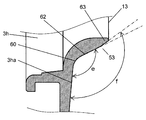
- FIG. 9 is a cross-sectional view of the outlet of the circulation path of the drum type washing machine in the fourth embodiment of the present invention.
- the same components as in the first to third embodiments will be described using the same reference numerals.
- the drum type washing machine 1 of the present embodiment is different from the third embodiment in that the guide surface 62 has a plurality of inclination angles.
- the guide surface 62 has an inclination angle e near the inclined surface 3ha connected via the curved surface 60.
- the guide surface 62 has an inclination angle f in the vicinity of the guide surface tip portion 63 that is the tip portion.
- the inclination angle is f> e.
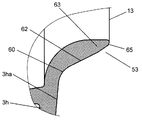
- FIG. 10A is a cross-sectional view of the jet outlet of the circulation path of the drum type washing machine in the fifth embodiment of the present invention.
- FIG. 10B is a cross-sectional view of another outlet of the circulation path of the drum type washing machine in the embodiment.
- the same components as in the first to fourth embodiments will be described using the same reference numerals.
- the drum-type washing machine 1 of the present embodiment is different from the fourth embodiment in the shape of the most distal portion of the guide surface 62.
- the most distal end of the guide surface 62 is the end of the back surface of the front wall 3h.
- the ejection angle of the washing water is affected by the tangential direction of the leading end portion of the guide surface 62. Therefore, the ejection angle of the washing water can be set according to the shape of the most distal portion of the guide surface 62.
- the most distal portion 65 of the guide surface 62 has a chamfered shape.
- the most distal portion 66 of the guide surface 62 has a rounded shape with a substantially arc-shaped cross section. With this shape, the catch of the laundry is further suppressed, and the damage to the laundry is further suppressed.
- FIG. 11 is a cross-sectional view of the outlet of the circulation path of the drum type washing machine in the sixth embodiment of the present invention.
- the same components as in the first to fourth embodiments will be described using the same reference numerals.
- the drum type washing machine 1 according to the present embodiment takes into account the expansion of the spray of washing water, the angle of ejection, the stability of the ejection, the damage of the laundry, and the uneven thickness of the resin forming the guide surface 64. 11 has an outlet 53 as shown in FIG.
- the ejection port 53 is formed by a guide surface 64 and a guide surface 64a having a plurality of inclination angles, and a curved surface 60, a curved surface 60a, a curved surface 60b, and a curved surface 60c having a plurality of curved radii.
- these surfaces are configured to be smoothly connected by gradually changing each of the surfaces. With this configuration, it is possible to set the expansion of the spray and the spray angle while considering the stability of the spray of washing water, the damage of the laundry, and the uneven thickness of the resin forming the guide surface 64.
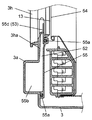
- FIG. 12 is a cross-sectional view of the vicinity of the discharge port of the circulation path of the drum type washing machine in the seventh embodiment of the present invention.
- the same configurations as those in Embodiment 1 will be described using the same reference numerals.
- the drum type washing machine 1 has a configuration in which washing water is ejected directly from the discharge port 55d toward the rotating drum 4.
- the discharge port 55 d is provided in the water tank 3 at a position facing the drum opening 54.
- the discharge port 55d and the jet port 53 are shared.
- This configuration eliminates the need for the guide surface 56 and the like that form the ejection port 53. That is, it is possible to eliminate the guide surface 56 and the like that may cause the laundry to be caught. Therefore, no trouble occurs when washing, rinsing or drying. Also, the laundry is not damaged or torn.
- the discharge port 55d can also be provided in a member constituting a seal such as the cover 55.
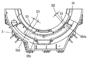
- FIG. 13 is the top view which looked at the front wall of the water tank of the drum type washing machine in Embodiment 8 of this invention from the inside.
- FIG. 14A is a cross-sectional view of the vicinity of the discharge port of the circulation path of the drum type washing machine in the same embodiment.
- FIG. 14B is a cross-sectional view of the vicinity of another discharge port of the circulation path of the drum type washing machine in the embodiment.
- FIG. 15A is a plan view of a front wall of another water tank of the drum type washing machine according to the embodiment as viewed from the inside.
- FIG. 15B is a plan view of a front wall of still another water tank of the drum type washing machine according to the embodiment as viewed from the inside.
- 16A is a cross-sectional view of the vicinity of still another discharge port of the circulation path of the drum type washing machine in the embodiment.
- 16B is a partial cross-sectional view taken along line 16B-16B in FIG. 16A.
- the same configurations as those in Embodiment 1 will be described using the same reference numerals.
- the opening width D1 that is the size in the circumferential direction of the opening of one discharge port 55d is the opening width D2 that is the size in the circumferential direction of the opening of the other discharge port 55da.
- Different. By varying the opening width, it is possible to vary the width and flow rate of the wash water jetted from the respective discharge ports 55d and 55da. Thereby, the ejection form of washing water can be set appropriately, and washing water can be appropriately supplied to the laundry even when the amount of laundry is large or small. Further, the cleaning effect is improved by appropriately supplying the cleaning water.
- the opening distance D3 which is the size in the direction perpendicular to the circumferential direction of the opening of one discharge port 55d, and the circumferential direction of the opening of the other discharge port 55da
- the opening distance D4 which is the size in the direction perpendicular to the vertical direction
- the washing water ejection form can be set appropriately, and the washing water can be appropriately supplied to the laundry even when the amount of laundry is large or small. Further, the cleaning effect is improved by appropriately supplying the cleaning water.
- the direction of the washing water ejected from the left and right ejection ports 53 can be varied by varying the opening angles of the left and right ejection ports with respect to the rotation center Q of the rotating drum 4. Can do.
- the opening angle will be described using the case of the discharge port 55da in FIG. 15A.
- the wash water ejected from the ejection port 53 through the ejection port 55da is ejected in the direction of arrow E.
- the direction of this arrow E is the opening direction E.
- An angle j formed by a line segment Qd connecting the opening of the discharge port 55da and the rotation center Q of the rotary drum 4 and the opening direction E is defined as an opening angle.
- the opening angle of the discharge port 55d in FIG. 15A is 0, and the opening angle of the discharge port 55db in FIG. 15B is k.
- the washing water ejected from the ejection port 53 through the ejection port 55d is ejected in the direction of the arrow F. That is, the opening direction is F. Since the opening direction F coincides with the direction of the rotation center Q of the rotary drum 4, the opening angle is zero. Further, the washing water ejected from the ejection port 53 through the ejection port 55db is ejected in the direction of the arrow G. That is, the opening direction is G. Since the opening direction G forms an angle k with the direction of the rotation center Q of the rotary drum 4, the opening angle is k.
- the cleaning water is ejected in the direction of arrow G by providing the guide portion 67 at the tip of the discharge port 55db. That is, the opening direction and the opening angle can be set by changing the shape of the tip of the discharge port.
- the guide surface 57 corresponding to the discharge port 55d, the guide surface 56 corresponding to the discharge port 55da, and the guide surface 57 corresponding to the discharge port 55db are each formed in an annular shape around the rotation center Q of the rotary drum 4.
- the cross-sectional shapes of the guide surface 56 and the guide surface 57 have the same shape with respect to the rotation center Q.
- the cleaning water flowing along the guide surface 56 and the guide surface 57 is bent suddenly in the direction toward the rotation center Q of the rotary drum 4 and gradually bent away from the direction toward the rotation center Q of the rotary drum 4. It is done.
- the wash water that has flowed toward the rotation center Q of the rotary drum 4 and passed through the discharge port 55d has a substantially symmetric shape and spreads relatively narrowly.
- the wash water that has passed through the discharge port 55db is greatly expanded and ejected.
- a rib 68 is provided inside the water conduit 55b and in the vicinity of the discharge port 55d in a direction that obstructs the flow of cleaning water.
- the rib 68 is formed by projecting a part of the cover 55.
- the rib 68 has a size that covers, for example, about 50% of the cross-sectional area of the water conduit 55b.
- the wash water that has flowed into the water conduit 55b through the circulation passage 16 has a velocity component in the same direction as the longitudinal direction of the water conduit 55b when discharged from the discharge port 55d. Due to the influence of the velocity component, the cleaning water is ejected while being inclined in the longitudinal direction of the water conduit 55b with respect to the direction from the discharge port 55d or the guide surface 56 toward the rotary drum 4.
- the rib 68 by providing the rib 68, the cleaning water that has flowed through the water conduit 55 b collides with the rib 68. Thereby, the speed component in the longitudinal direction of the cleaning water is reduced, and the cleaning water is ejected from the discharge port 55d and the guide surface 56 along the direction toward the rotary drum 4.
- the washing water is ejected in a direction corresponding to the direction of the discharge port 55d and the guide surface 56.
- the rib 68 can also be provided inside the water conduit 55b in the vicinity of the discharge port 55da or the discharge port 55db.
- the drum type washing machine according to the present invention can supply washing water having an optimal ejection angle and spread, regardless of whether the amount of laundry is large or small. For this reason, it can utilize for the washing machine which has a rotating drum.
Abstract
Description
図1は、本発明の実施の形態1におけるドラム式洗濯機の断面図である。図2Aは、同実施の形態におけるドラム式洗濯機に搭載される循環ポンプの断面図である。図2Bは、同実施の形態におけるドラム式洗濯機に搭載される循環ポンプの側面図である。
図7Aは、本発明の実施の形態2におけるドラム式洗濯機の循環経路の吐出口近傍の断面図である。図7Bは、同実施の形態におけるドラム式洗濯機の循環経路の他の吐出口近傍の断面図である。実施の形態1と同じ構成については、同じ符号を用いて説明する。
図8は、本発明の実施の形態3におけるドラム式洗濯機の循環経路の吐出口の断面図である。実施の形態1と同じ構成については、同じ符号を用いて説明する。
図9は、本発明の実施の形態4におけるドラム式洗濯機の循環経路の噴出口の断面図である。実施の形態1~3と同じ構成については、同じ符号を用いて説明する。
図10Aは、本発明の実施の形態5におけるドラム式洗濯機の循環経路の噴出口の断面図である。図10Bは、同実施の形態におけるドラム式洗濯機の循環経路の他の噴出口の断面図である。実施の形態1~4と同じ構成については、同じ符号を用いて説明する。
図11は、本発明の実施の形態6におけるドラム式洗濯機の循環経路の噴出口の断面図である。実施の形態1~4と同じ構成については、同じ符号を用いて説明する。本実施の形態のドラム式洗濯機1は、洗浄水の噴出の拡がりや噴出角度、噴出の安定性、また、洗濯物の傷みや、案内面64を形成する樹脂の偏肉を考慮し、図11に示すような噴出口53を有する。具体的には、噴出口53は、複数の傾斜角度を有する案内面64や案内面64a、また、複数の湾曲半径を有する湾曲面60、湾曲面60a、湾曲面60b、湾曲面60cにより形成される。さらに、これらの面は、各々を徐変することにより、滑らかに繋いで構成される。この構成により、洗浄水の噴出の安定性、また、洗濯物の傷みや、案内面64を形成する樹脂の偏肉を考慮しつつ、噴出の拡がりや噴出角度を設定することができる。
図12は、本発明の実施の形態7におけるドラム式洗濯機の循環経路の吐出口近傍の断面図である。実施の形態1と同じ構成については、同じ符号を用いて説明する。
図13は、本発明の実施の形態8におけるドラム式洗濯機の水槽の前面壁を内方から見た平面図である。図14Aは、同実施の形態におけるドラム式洗濯機の循環経路の吐出口近傍の断面図である。図14Bは、同実施の形態におけるドラム式洗濯機の循環経路の他の吐出口近傍の断面図である。図15Aは、同実施の形態におけるドラム式洗濯機の他の水槽の前面壁を内方から見た平面図である。図15Bは、同実施の形態におけるドラム式洗濯機のさらに他の水槽の前面壁を内方から見た平面図である。図16Aは、同実施の形態におけるドラム式洗濯機の循環経路のさらに他の吐出口近傍の断面図である。図16Bは、図16Aにおける16B-16B線における部分断面図である。実施の形態1と同じ構成については、同じ符号を用いて説明する。
2 筐体
2a ベースプレート
2b 本体開口
3 水槽
3a 膨出部
3h 前面壁
3ha 傾斜面
4 回転ドラム
4b 前面壁
5 扉
6 モータ
7 給水ユニット
8 排水ユニット
9 乾燥ユニット
13 水槽開口
14 シール材
16 循環経路
16b 吐出側経路
19 排水弁
20 循環ポンプ
20a インペラ
20b ポンプケーシング
20c 循環モータ
20d モータケーシング
20da 軸受隔壁
20e モータ軸
20f 循環ポンプ吸入口
20g 循環ポンプ吐出口
21 操作パネル
22 制御ユニット
30 外底面
35 取り付け座
51 連結部
52 流路
53 噴出口
54 ドラム開口
55 カバー
55a パッキン
55b 導水路
55c 切欠き部
55d 吐出口
55da 吐出口
55db 吐出口
55f ネジ
56 案内面
57 案内面
58 案内面
59 案内面
60 湾曲面
60a 湾曲面
60b 湾曲面
60c 湾曲面
61 案内面
62 案内面
63 案内面先端部
64 案内面
64a 案内面
65 最先端部
66 最先端部
67 案内部
68 リブ
Claims (19)
- 筐体と、
前記筐体の内部に設けられ、水槽開口を有する有底円筒形の水槽と、
前記水槽の内部に設けられ、ドラム開口を有する有底円筒形の回転ドラムと、
前記水槽の外底面に装着され、前記回転ドラムを、水平または底に向かって下向きに傾斜した回転軸で回転させるモータと、
前記水槽の底側と前記水槽開口側とを連通し、前記水槽の内部の洗浄水を前記底側から前記水槽開口側へと循環させる循環経路と、
前記循環経路によって循環される洗浄水を、前記回転ドラムの内部に向かって噴出させる複数の噴出口とを備えるドラム式洗濯機。 - 前記複数の噴出口から噴出する洗浄水は、それぞれ噴出方向が異なる請求項1に記載のドラム式洗濯機。
- 前記複数の噴出口は、前記ドラム開口の中心を通る垂線に対して、左右に配設された請求項2に記載のドラム式洗濯機。
- 前記複数の噴出口から噴出する洗浄水は、それぞれ拡がり角度が異なる請求項2に記載のドラム式洗濯機。
- 前記複数の噴出口から、洗浄水が同時に噴出する請求項2に記載のドラム式洗濯機。
- 前記水槽の前面壁の裏面と前記回転ドラムの前面壁の表面との間を通って、前記噴出口から前記回転ドラムの内部に、洗浄水が噴出する請求項2に記載のドラム式洗濯機。
- 前記水槽の前面壁に設けられ、前記循環経路に接続される導水路と、
前記導水路に設けられ、前記水槽の前面壁の裏面と前記回転ドラムの前面壁の表面との間に洗浄水を吐出させる複数の吐出口と、
前記水槽の前面壁の裏面に形成され、前記吐出口から吐出した洗浄水を、前記噴出口へ案内する複数の案内面とをさらに備え、
前記複数の案内面の形状は、2種類以上からなる請求項1に記載のドラム式洗濯機。 - 前記複数の案内面は傾斜面で構成され、前記傾斜面の傾斜角度は2種類以上からなる請求項7に記載のドラム式洗濯機。
- 前記複数の案内面は湾曲面で構成され、前記湾曲面の湾曲半径は2種類以上からなる請求項7に記載のドラム式洗濯機。
- 前記複数の案内面の少なくとも1つは、湾曲面と傾斜面とから構成される請求項7に記載のドラム式洗濯機。
- 前記複数の案内面の少なくとも1つは、複数の傾斜角度を有する請求項7に記載のドラム式洗濯機。
- 前記複数の案内面の最先端部は、面取り形状を有する請求項7に記載のドラム式洗濯機。
- 前記案内面の最先端部は、断面が円弧の丸みを帯びた形状を有する請求項7に記載のドラム式洗濯機。
- 前記導水路の内部であって、前記複数の吐出口の少なくとも1つの近傍に、洗浄水の流れを妨げるリブを設けた請求項7に記載のドラム式洗濯機。
- 前記水槽の前面壁に設けられ、前記循環経路に接続される導水路と、
前記導水路に設けられ、前記水槽の前面壁の裏面と前記回転ドラムの前面壁の表面との間に洗浄水を吐出させる複数の吐出口と、
前記水槽の前面壁の裏面に形成され、前記吐出口から吐出した洗浄水を、前記噴出口へ案内する複数の案内面とをさらに備え、
前記複数の吐出口の形状は、2種類以上からなる請求項1に記載のドラム式洗濯機。 - 前記複数の吐出口は前記回転ドラムの回転中心に向く開口を有し、前記複数の吐出口の前記開口の円周方向の大きさである開口幅は、それぞれ異なる請求項15に記載のドラム式洗濯機。
- 前記複数の吐出口は前記回転ドラムの回転中心に向く開口を有し、前記複数の吐出口の前記開口の円周方向に対して垂直な方向の大きさである開口距離は、それぞれ異なる請求項15に記載のドラム式洗濯機。
- 前記複数の吐出口の少なくとも1つは、前記回転ドラムの回転中心からずれた方向に向く開口を有する請求項15に記載のドラム式洗濯機。
- 前記導水路の内部であって、前記吐出口の少なくとも1つの近傍に、洗浄水の流れを妨げるリブを設けた請求項15に記載のドラム式洗濯機。
Priority Applications (3)
| Application Number | Priority Date | Filing Date | Title |
|---|---|---|---|
| CN201080038123.4A CN102482834B (zh) | 2009-08-27 | 2010-08-18 | 滚筒式洗衣机 |
| EP10811468.7A EP2471992B1 (en) | 2009-08-27 | 2010-08-18 | Drum type washing machine |
| US13/390,666 US20120137740A1 (en) | 2009-08-27 | 2010-08-18 | Drum type washing machine |
Applications Claiming Priority (6)
| Application Number | Priority Date | Filing Date | Title |
|---|---|---|---|
| JP2009-196248 | 2009-08-27 | ||
| JP2009196249A JP5397093B2 (ja) | 2009-08-27 | 2009-08-27 | ドラム式洗濯機 |
| JP2009-196250 | 2009-08-27 | ||
| JP2009196248A JP5397092B2 (ja) | 2009-08-27 | 2009-08-27 | ドラム式洗濯機 |
| JP2009-196249 | 2009-08-27 | ||
| JP2009196250A JP5299174B2 (ja) | 2009-08-27 | 2009-08-27 | ドラム式洗濯機 |
Publications (1)
| Publication Number | Publication Date |
|---|---|
| WO2011024409A1 true WO2011024409A1 (ja) | 2011-03-03 |
Family
ID=43627531
Family Applications (1)
| Application Number | Title | Priority Date | Filing Date |
|---|---|---|---|
| PCT/JP2010/005097 WO2011024409A1 (ja) | 2009-08-27 | 2010-08-18 | ドラム式洗濯機 |
Country Status (5)
| Country | Link |
|---|---|
| US (1) | US20120137740A1 (ja) |
| EP (1) | EP2471992B1 (ja) |
| CN (2) | CN102482834B (ja) |
| TW (1) | TW201111578A (ja) |
| WO (1) | WO2011024409A1 (ja) |
Cited By (9)
| Publication number | Priority date | Publication date | Assignee | Title |
|---|---|---|---|---|
| EP2845941A1 (en) * | 2011-04-14 | 2015-03-11 | LG Electronics, Inc. | Washing machine with supply nozzles |
| WO2016027404A1 (ja) * | 2014-08-18 | 2016-02-25 | パナソニックIpマネジメント株式会社 | 洗濯機 |
| JP2016041152A (ja) * | 2014-08-18 | 2016-03-31 | パナソニックIpマネジメント株式会社 | 洗濯機 |
| JP2016043182A (ja) * | 2014-08-26 | 2016-04-04 | パナソニックIpマネジメント株式会社 | 洗濯機 |
| JP2016043184A (ja) * | 2014-08-26 | 2016-04-04 | パナソニックIpマネジメント株式会社 | 洗濯機 |
| JP2016043183A (ja) * | 2014-08-26 | 2016-04-04 | パナソニックIpマネジメント株式会社 | 洗濯機 |
| JP2016043181A (ja) * | 2014-08-26 | 2016-04-04 | パナソニックIpマネジメント株式会社 | 洗濯機 |
| JP2016043180A (ja) * | 2014-08-26 | 2016-04-04 | パナソニックIpマネジメント株式会社 | 洗濯機 |
| CN109939821A (zh) * | 2019-04-09 | 2019-06-28 | 林阳辉 | 一种新型高效尾矿磁选回收设备 |
Families Citing this family (8)
| Publication number | Priority date | Publication date | Assignee | Title |
|---|---|---|---|---|
| EP2703547A1 (en) | 2012-08-29 | 2014-03-05 | Electrolux Home Products Corporation N.V. | Laundry washing machine |
| EP2703546A1 (en) | 2012-08-29 | 2014-03-05 | Electrolux Home Products Corporation N.V. | Laundry washing machine |
| ES2446115B1 (es) * | 2012-09-06 | 2015-03-06 | Bsh Electrodomesticos Espana | Junta anular de embocadura para una máquina lavadora de carga frontal con sistema de remojado de colada y máquina lavadora de carga frontal que comprende la junta |
| DE102014220020A1 (de) * | 2014-10-02 | 2016-04-07 | BSH Hausgeräte GmbH | Wäschepflegegerät mit einem Umlenkelement |
| JP6990824B2 (ja) * | 2017-02-14 | 2022-01-12 | パナソニックIpマネジメント株式会社 | 洗濯機 |
| CN110387708A (zh) * | 2018-04-16 | 2019-10-29 | 青岛海尔滚筒洗衣机有限公司 | 滚筒洗衣机及其喷淋系统 |
| CN110468551B (zh) * | 2018-05-10 | 2021-11-05 | 青岛海尔洗涤电器有限公司 | 滚筒洗衣机及其喷淋控制方法 |
| CN117888337A (zh) | 2019-05-23 | 2024-04-16 | 惠而浦公司 | 洗衣设备 |
Citations (6)
| Publication number | Priority date | Publication date | Assignee | Title |
|---|---|---|---|---|
| JPH07231994A (ja) * | 1994-02-24 | 1995-09-05 | Sharp Corp | ドラム式洗濯機 |
| JPH09299684A (ja) * | 1996-05-16 | 1997-11-25 | Matsushita Electric Ind Co Ltd | 洗濯機 |
| JPH10127978A (ja) | 1996-10-30 | 1998-05-19 | Sharp Corp | ドラム式洗濯機 |
| JP2002282587A (ja) | 2001-03-23 | 2002-10-02 | Mitsubishi Electric Corp | 洗濯機 |
| JP2006192249A (ja) * | 2005-01-10 | 2006-07-27 | Lg Electronics Inc | ドラム洗濯機 |
| JP2008073128A (ja) | 2006-09-20 | 2008-04-03 | Hitachi Appliances Inc | ドラム式洗濯機 |
Family Cites Families (10)
| Publication number | Priority date | Publication date | Assignee | Title |
|---|---|---|---|---|
| US2322559A (en) * | 1940-01-24 | 1943-06-22 | Westinghouse Electric & Mfg Co | Laundry apparatus |
| DE3811583A1 (de) * | 1988-04-07 | 1989-10-19 | Licentia Gmbh | Stirnseitig beschickbare trommelwaschmaschine |
| DE4330079C2 (de) * | 1993-09-06 | 2000-05-11 | Bsh Bosch Siemens Hausgeraete | Frontseitig beschickbare Trommelwaschmaschine |
| JP3915307B2 (ja) * | 1999-03-30 | 2007-05-16 | 松下電器産業株式会社 | 洗濯機 |
| DE10227958A1 (de) * | 2002-06-22 | 2004-01-08 | Electrolux Home Products Corporation N.V. | Waschmaschine |
| KR100688160B1 (ko) * | 2003-08-07 | 2007-03-02 | 엘지전자 주식회사 | 프론트 로딩 타입 드럼 세탁기 |
| US7424810B2 (en) * | 2004-06-15 | 2008-09-16 | General Electric Company | Washing machine with water direction device |
| KR20050121052A (ko) * | 2004-06-21 | 2005-12-26 | 삼성전자주식회사 | 세탁기 |
| JP5053723B2 (ja) * | 2007-06-15 | 2012-10-17 | 株式会社東芝 | ドラム式洗濯機及び洗濯方法 |
| KR20090107164A (ko) * | 2008-04-08 | 2009-10-13 | 엘지전자 주식회사 | 세탁기 |
-
2010
- 2010-08-18 CN CN201080038123.4A patent/CN102482834B/zh active Active
- 2010-08-18 CN CN201410653272.1A patent/CN104313835B/zh active Active
- 2010-08-18 EP EP10811468.7A patent/EP2471992B1/en not_active Not-in-force
- 2010-08-18 US US13/390,666 patent/US20120137740A1/en not_active Abandoned
- 2010-08-18 WO PCT/JP2010/005097 patent/WO2011024409A1/ja active Application Filing
- 2010-08-24 TW TW099128250A patent/TW201111578A/zh unknown
Patent Citations (6)
| Publication number | Priority date | Publication date | Assignee | Title |
|---|---|---|---|---|
| JPH07231994A (ja) * | 1994-02-24 | 1995-09-05 | Sharp Corp | ドラム式洗濯機 |
| JPH09299684A (ja) * | 1996-05-16 | 1997-11-25 | Matsushita Electric Ind Co Ltd | 洗濯機 |
| JPH10127978A (ja) | 1996-10-30 | 1998-05-19 | Sharp Corp | ドラム式洗濯機 |
| JP2002282587A (ja) | 2001-03-23 | 2002-10-02 | Mitsubishi Electric Corp | 洗濯機 |
| JP2006192249A (ja) * | 2005-01-10 | 2006-07-27 | Lg Electronics Inc | ドラム洗濯機 |
| JP2008073128A (ja) | 2006-09-20 | 2008-04-03 | Hitachi Appliances Inc | ドラム式洗濯機 |
Non-Patent Citations (1)
| Title |
|---|
| See also references of EP2471992A4 * |
Cited By (12)
| Publication number | Priority date | Publication date | Assignee | Title |
|---|---|---|---|---|
| EP2845941A1 (en) * | 2011-04-14 | 2015-03-11 | LG Electronics, Inc. | Washing machine with supply nozzles |
| US9394644B2 (en) | 2011-04-14 | 2016-07-19 | Lg Electronics Inc. | Washer |
| US9765465B2 (en) | 2011-04-14 | 2017-09-19 | Lg Electronics Inc. | Washer |
| WO2016027404A1 (ja) * | 2014-08-18 | 2016-02-25 | パナソニックIpマネジメント株式会社 | 洗濯機 |
| JP2016041152A (ja) * | 2014-08-18 | 2016-03-31 | パナソニックIpマネジメント株式会社 | 洗濯機 |
| JP2016043182A (ja) * | 2014-08-26 | 2016-04-04 | パナソニックIpマネジメント株式会社 | 洗濯機 |
| JP2016043184A (ja) * | 2014-08-26 | 2016-04-04 | パナソニックIpマネジメント株式会社 | 洗濯機 |
| JP2016043183A (ja) * | 2014-08-26 | 2016-04-04 | パナソニックIpマネジメント株式会社 | 洗濯機 |
| JP2016043181A (ja) * | 2014-08-26 | 2016-04-04 | パナソニックIpマネジメント株式会社 | 洗濯機 |
| JP2016043180A (ja) * | 2014-08-26 | 2016-04-04 | パナソニックIpマネジメント株式会社 | 洗濯機 |
| CN109939821A (zh) * | 2019-04-09 | 2019-06-28 | 林阳辉 | 一种新型高效尾矿磁选回收设备 |
| CN109939821B (zh) * | 2019-04-09 | 2021-02-05 | 林阳辉 | 一种新型高效尾矿磁选回收设备 |
Also Published As
| Publication number | Publication date |
|---|---|
| CN102482834B (zh) | 2014-12-17 |
| US20120137740A1 (en) | 2012-06-07 |
| CN104313835B (zh) | 2017-04-05 |
| CN102482834A (zh) | 2012-05-30 |
| EP2471992A4 (en) | 2013-07-31 |
| EP2471992B1 (en) | 2016-10-12 |
| CN104313835A (zh) | 2015-01-28 |
| TW201111578A (en) | 2011-04-01 |
| EP2471992A1 (en) | 2012-07-04 |
Similar Documents
| Publication | Publication Date | Title |
|---|---|---|
| WO2011024409A1 (ja) | ドラム式洗濯機 | |
| JP5406212B2 (ja) | 洗濯装置 | |
| JP4741041B2 (ja) | 透過方式洗濯機、その制御方法及び透過方式洗濯機用タブカバー | |
| JP3124903B2 (ja) | 洗濯機の水流生起装置 | |
| WO2013035278A1 (ja) | ドラム式洗濯機 | |
| CN102482835B (zh) | 滚筒式洗衣机 | |
| WO2013035277A1 (ja) | ドラム式洗濯機 | |
| WO2017064830A1 (ja) | 洗濯機 | |
| JP5299174B2 (ja) | ドラム式洗濯機 | |
| JP3046016B2 (ja) | 洗濯機 | |
| JP4973707B2 (ja) | ドラム式洗濯機 | |
| JPH1119376A (ja) | 洗濯機 | |
| JP5397093B2 (ja) | ドラム式洗濯機 | |
| WO2019150837A1 (ja) | 洗濯機 | |
| KR102488736B1 (ko) | 세제공급장치를 갖는 세탁기 | |
| KR20110098485A (ko) | 액체 분사 장치를 갖는 세탁기 | |
| JP2011055977A (ja) | ドラム式洗濯機 | |
| JP6260008B2 (ja) | ドラム式洗濯機 | |
| WO2023032588A1 (ja) | 洗濯機 | |
| JP5891407B2 (ja) | ドラム式洗濯機 | |
| KR100218969B1 (ko) | 세탁기 | |
| JP5397092B2 (ja) | ドラム式洗濯機 | |
| KR100292267B1 (ko) | 세탁기의펄세이터 | |
| JP2023033701A (ja) | 洗濯機 | |
| JP6260009B2 (ja) | ドラム式洗濯機 |
Legal Events
| Date | Code | Title | Description |
|---|---|---|---|
| WWE | Wipo information: entry into national phase |
Ref document number: 201080038123.4 Country of ref document: CN |
|
| 121 | Ep: the epo has been informed by wipo that ep was designated in this application |
Ref document number: 10811468 Country of ref document: EP Kind code of ref document: A1 |
|
| REEP | Request for entry into the european phase |
Ref document number: 2010811468 Country of ref document: EP |
|
| WWE | Wipo information: entry into national phase |
Ref document number: 2010811468 Country of ref document: EP |
|
| WWE | Wipo information: entry into national phase |
Ref document number: 13390666 Country of ref document: US |
|
| NENP | Non-entry into the national phase |
Ref country code: DE |