WO2011007728A1 - 透明フィルムおよびその利用 - Google Patents
透明フィルムおよびその利用 Download PDFInfo
- Publication number
- WO2011007728A1 WO2011007728A1 PCT/JP2010/061694 JP2010061694W WO2011007728A1 WO 2011007728 A1 WO2011007728 A1 WO 2011007728A1 JP 2010061694 W JP2010061694 W JP 2010061694W WO 2011007728 A1 WO2011007728 A1 WO 2011007728A1
- Authority
- WO
- WIPO (PCT)
- Prior art keywords
- layer
- transparent film
- back layer
- resin
- base material
- Prior art date
- Legal status (The legal status is an assumption and is not a legal conclusion. Google has not performed a legal analysis and makes no representation as to the accuracy of the status listed.)
- Ceased
Links
Images

Classifications
-
- B—PERFORMING OPERATIONS; TRANSPORTING
- B32—LAYERED PRODUCTS
- B32B—LAYERED PRODUCTS, i.e. PRODUCTS BUILT-UP OF STRATA OF FLAT OR NON-FLAT, e.g. CELLULAR OR HONEYCOMB, FORM
- B32B27/00—Layered products comprising a layer of synthetic resin
- B32B27/06—Layered products comprising a layer of synthetic resin as the main or only constituent of a layer, which is next to another layer of the same or of a different material
- B32B27/08—Layered products comprising a layer of synthetic resin as the main or only constituent of a layer, which is next to another layer of the same or of a different material of synthetic resin
-
- C—CHEMISTRY; METALLURGY
- C08—ORGANIC MACROMOLECULAR COMPOUNDS; THEIR PREPARATION OR CHEMICAL WORKING-UP; COMPOSITIONS BASED THEREON
- C08J—WORKING-UP; GENERAL PROCESSES OF COMPOUNDING; AFTER-TREATMENT NOT COVERED BY SUBCLASSES C08B, C08C, C08F, C08G or C08H
- C08J5/00—Manufacture of articles or shaped materials containing macromolecular substances
- C08J5/18—Manufacture of films or sheets
-
- C—CHEMISTRY; METALLURGY
- C09—DYES; PAINTS; POLISHES; NATURAL RESINS; ADHESIVES; COMPOSITIONS NOT OTHERWISE PROVIDED FOR; APPLICATIONS OF MATERIALS NOT OTHERWISE PROVIDED FOR
- C09J—ADHESIVES; NON-MECHANICAL ASPECTS OF ADHESIVE PROCESSES IN GENERAL; ADHESIVE PROCESSES NOT PROVIDED FOR ELSEWHERE; USE OF MATERIALS AS ADHESIVES
- C09J7/00—Adhesives in the form of films or foils
- C09J7/20—Adhesives in the form of films or foils characterised by their carriers
- C09J7/29—Laminated material
-
- G—PHYSICS
- G02—OPTICS
- G02B—OPTICAL ELEMENTS, SYSTEMS OR APPARATUS
- G02B1/00—Optical elements characterised by the material of which they are made; Optical coatings for optical elements
- G02B1/10—Optical coatings produced by application to, or surface treatment of, optical elements
-
- G—PHYSICS
- G02—OPTICS
- G02B—OPTICAL ELEMENTS, SYSTEMS OR APPARATUS
- G02B1/00—Optical elements characterised by the material of which they are made; Optical coatings for optical elements
- G02B1/10—Optical coatings produced by application to, or surface treatment of, optical elements
- G02B1/14—Protective coatings, e.g. hard coatings
-
- G—PHYSICS
- G02—OPTICS
- G02B—OPTICAL ELEMENTS, SYSTEMS OR APPARATUS
- G02B1/00—Optical elements characterised by the material of which they are made; Optical coatings for optical elements
- G02B1/10—Optical coatings produced by application to, or surface treatment of, optical elements
- G02B1/16—Optical coatings produced by application to, or surface treatment of, optical elements having an anti-static effect, e.g. electrically conducting coatings
-
- B—PERFORMING OPERATIONS; TRANSPORTING
- B32—LAYERED PRODUCTS
- B32B—LAYERED PRODUCTS, i.e. PRODUCTS BUILT-UP OF STRATA OF FLAT OR NON-FLAT, e.g. CELLULAR OR HONEYCOMB, FORM
- B32B2307/00—Properties of the layers or laminate
- B32B2307/20—Properties of the layers or laminate having particular electrical or magnetic properties, e.g. piezoelectric
- B32B2307/21—Anti-static
-
- C—CHEMISTRY; METALLURGY
- C09—DYES; PAINTS; POLISHES; NATURAL RESINS; ADHESIVES; COMPOSITIONS NOT OTHERWISE PROVIDED FOR; APPLICATIONS OF MATERIALS NOT OTHERWISE PROVIDED FOR
- C09J—ADHESIVES; NON-MECHANICAL ASPECTS OF ADHESIVE PROCESSES IN GENERAL; ADHESIVE PROCESSES NOT PROVIDED FOR ELSEWHERE; USE OF MATERIALS AS ADHESIVES
- C09J2301/00—Additional features of adhesives in the form of films or foils
- C09J2301/30—Additional features of adhesives in the form of films or foils characterized by the chemical, physicochemical or physical properties of the adhesive or the carrier
- C09J2301/302—Additional features of adhesives in the form of films or foils characterized by the chemical, physicochemical or physical properties of the adhesive or the carrier the adhesive being pressure-sensitive, i.e. tacky at temperatures inferior to 30°C
-
- Y—GENERAL TAGGING OF NEW TECHNOLOGICAL DEVELOPMENTS; GENERAL TAGGING OF CROSS-SECTIONAL TECHNOLOGIES SPANNING OVER SEVERAL SECTIONS OF THE IPC; TECHNICAL SUBJECTS COVERED BY FORMER USPC CROSS-REFERENCE ART COLLECTIONS [XRACs] AND DIGESTS
- Y10—TECHNICAL SUBJECTS COVERED BY FORMER USPC
- Y10T—TECHNICAL SUBJECTS COVERED BY FORMER US CLASSIFICATION
- Y10T428/00—Stock material or miscellaneous articles
- Y10T428/26—Web or sheet containing structurally defined element or component, the element or component having a specified physical dimension
Definitions
- the present invention relates to a transparent film that is less likely to be scratched on the back surface and excellent in printability, and a surface protective film including the film.
- the surface protective film (also referred to as a surface protective sheet) generally has a configuration in which an adhesive is provided on a film-like support. Such a protective film is attached to an adherend via the pressure-sensitive adhesive, and is used for the purpose of protecting the adherend from scratches and dirt during processing and transportation.
- a polarizing plate to be bonded to a liquid crystal cell in the production of a liquid crystal display panel is once manufactured in a roll form, and then unwound from the roll and cut into a desired size according to the shape of the liquid crystal cell.
- a film having transparency can be preferably used since an appearance inspection of an adherend (for example, a polarizing plate) can be performed with the film attached.
- an appearance inspection of an adherend for example, a polarizing plate
- the required level for the appearance quality of the surface protection film has been increased from the viewpoint of the ease of appearance inspection.
- the property that the back surface of the surface protective film (the surface opposite to the surface attached to the adherend) is not easily scratched. This is because if the surface protective film has scratches, it cannot be determined whether the surface protective film is attached to the adherend or the surface protective film.
- an object of the present invention is to provide a transparent film that is hardly scratched on the back surface (that is, excellent in scratch resistance) and excellent in printability, and is therefore suitable for use as a support for a surface protective film.
- Another object of the present invention is to provide a surface protective film having a structure having an adhesive layer on one side of the transparent film.
- the inventor paid attention to the fact that the friction coefficient of the back layer in the surface protective film is likely to change with time, and examined in detail the relationship between the stability of the friction coefficient with time and the scratch resistance and other characteristics. As a result, the inventors have found that the scratch resistance and printability can be stably achieved at a high level by suppressing the change with time of the friction coefficient to a predetermined level or less, and the present invention has been completed.
- the transparent film provided by the present invention has a base material layer made of a transparent resin material and a back surface layer provided on the first surface of the base material layer.
- the back layer has a thickness of 1 ⁇ m or less.
- the transparent film has a friction coefficient ⁇ 50 of the back layer after storage for 3 days at a temperature of 50 ° C. and a relative humidity of 15%, and a friction of the back layer after storage for 3 days at a temperature of 80 ° C. and a relative humidity of 80%.
- both the friction coefficient mu 50 the absolute value of the difference ⁇ 80
- both friction coefficient mu 50 the smaller the value of mu 80 (hereinafter, this "min (mu 50 , ⁇ 80 ) ”)), and the coefficient of friction variation ⁇ obtained by dividing by 50 ) is less than 10% (typically 0 or more and less than 10%).
- ⁇
- ⁇
- ⁇
- a transparent film that satisfies ⁇ ⁇ 10% (typically 0 ⁇ ⁇ ⁇ 10%) has little change over time in the surface condition of the back layer, so it exhibits stable scratch resistance and printability at a high level. Can be.
- the transparent film which shows high scratch resistance and printability stably is suitable as a support body of a surface protection film.
- the said back layer is small in thickness, it has little influence on the characteristics (optical characteristics, dimensional stability, etc.) of a base material layer, and is preferable.
- the thickness of the back layer is more than 1 ⁇ m, when the back layer contains components that are easily colored, the coloring of the entire transparent film becomes conspicuous, or curing shrinkage occurs with the formation of the back layer Since the transparent film may easily curl due to the shrinkage, reducing the thickness of the back layer within a range where desired performance (for example, scratch resistance) is realized prevents the above-mentioned coloring and curling. Or it is preferable also from the point that it can reduce.
- the resin material constituting the base material layer a material using a polyester resin such as polyethylene terephthalate resin or polyethylene naphthalate resin as a base resin can be preferably used.
- the friction coefficients ⁇ 50 and ⁇ 80 are both 0.4 or less (for example, 0.2 or more and 0.4 or less).
- a transparent film satisfying the friction coefficient fluctuation rate ⁇ and the friction coefficients ⁇ 50 and ⁇ 80 can exhibit higher scratch resistance in addition to good printability.
- the transparent film disclosed herein has a peeling force measured by applying an adhesive tape to the back layer, and peeling the adhesive tape from the back layer at a peeling speed of 0.3 m / min and a peeling angle of 180 degrees. It is preferable that (back surface peeling force) is 2 N / 19 mm or more.
- a transparent film exhibiting such peeling force is suitable as a support for the surface protective film. That is, the surface protective film that has finished its protective function is removed by peeling off from the adherend (for example, an optical member such as a polarizing plate). At this time, the surface protective film is removed by separating the end of the surface protective film from the adherend by applying the adhesive tape to the back surface (surface of the back layer) of the surface protective film and pulling the adhesive tape. The workability at the time can be improved and the burden on the adherend can be reduced.
- the surface protective film using the transparent film as a support is suitable for a peeling operation using the pressure-sensitive adhesive tape because the back layer has an appropriate peeling force.
- the structure of the back layer is preferably a single layer structure from the viewpoint of strength and productivity. Moreover, it is preferable that the said back surface layer is provided directly on the 1st surface of the said base material layer. In the configuration in which one or more intermediate layers are interposed between the back layer and the base material layer, the adhesion between the intermediate layer, the base material layer, and the back surface layer is insufficient, and the scratch resistance of the back layer is reduced. May decrease. Therefore, it is advantageous to employ a configuration in which the back layer is directly provided on the base material layer.
- the back layer is made of a resin material containing a lubricant.
- lubricant refers to a component having an action of reducing the coefficient of friction when blended with a resin material.
- a back layer made of a resin material containing a lubricant is preferable because a transparent film excellent in scratch resistance is easily realized.
- the use of the above-mentioned lubricant is also advantageous for realizing a transparent film satisfying the preferred coefficient of friction disclosed herein (particularly ⁇ 50 ).
- a reactive lubricant having a functional group capable of binding to the resin component of the back layer can be preferably used. Since such a reactive lubricant can be restrained from moving by combining with the resin component of the back layer, the amount of bleed on the back layer surface increases over time, or conversely, the abundance in the back layer increases over time. It is hard to happen that it becomes too small. Therefore, according to such a reactive lubricant, it is easy to obtain a transparent film satisfying the preferable coefficient of friction variation ⁇ disclosed herein.
- the back layer is made of a resin material containing an antistatic component.
- scratch resistance and antistatic properties can be imparted using the back layer. Therefore, the productivity of the transparent film is better than the configuration in which the antistatic layer is provided separately from the back layer.
- adhesion between the back surface layer and the base material layer can be improved as compared with the configuration in which the antistatic layer is interposed between the back surface layer and the base material layer, a transparent film having excellent scratch resistance is realized.
- the antistatic component a conductive polymer can be preferably employed because it is easy to achieve both good antistatic properties and high scratch resistance.
- a surface protective film provided with any transparent film disclosed herein as a support.
- the surface protective film typically includes the transparent film and an adhesive layer provided on the surface of the transparent film opposite to the back layer.
- Such a surface protective film is particularly suitable as a surface protective film for optical parts.
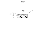
- FIG. 1 is a schematic cross-sectional view showing one structural example of the surface protective film according to the present invention.
- FIG. 2 is a schematic cross-sectional view showing another configuration example of the surface protective film according to the present invention.
- the transparent film disclosed herein is excellent in scratch resistance and exhibits good printability, so that it can be preferably used for a support of an adhesive sheet and other uses.
- a pressure-sensitive adhesive sheet may generally have a form called a pressure-sensitive adhesive tape, a pressure-sensitive adhesive label, a pressure-sensitive adhesive film, or the like.
- it is suitable as a support for a surface protective film, and since it can accurately inspect the appearance of products through the film, it is particularly used as an optical component (for example, a liquid crystal display panel component such as a polarizing plate or a wave plate).
- an optical component for example, a liquid crystal display panel component such as a polarizing plate or a wave plate.
- the surface protective film disclosed herein is characterized by having an adhesive layer on one side of the transparent film.
- the pressure-sensitive adhesive layer is typically formed continuously, but is not limited to such a form.
- the pressure-sensitive adhesive layer is a pressure-sensitive adhesive layer formed in a regular or random pattern such as a spot or stripe. There may be.
- the surface protective film disclosed herein may be in the form of a roll or a single sheet.
- FIG. 1 schematically shows a typical configuration example of a surface protective film having a transparent film disclosed herein as a support.
- the surface protective film 1 includes a transparent film (support) 10 and an adhesive layer 20.
- the transparent film 10 includes a base material layer 12 made of a transparent resin film and a back layer 14 having a thickness of 1 ⁇ m or less provided directly on the first surface 12A.
- the pressure-sensitive adhesive layer 20 is provided on the surface of the transparent film 10 opposite to the back layer 14.
- the surface protective film 1 is used by sticking the pressure-sensitive adhesive layer 20 to an adherend (a surface to be protected, for example, the surface of an optical component such as a polarizing plate). As shown in FIG.
- the protective film 1 before use typically has at least the pressure-sensitive adhesive on the surface of the pressure-sensitive adhesive layer 20 (sticking surface to the adherend). It may be in a form protected by a release liner 30 having a release surface on the layer 20 side. Or the form by which the adhesive layer 20 contact
- the base layer of the transparent film disclosed herein can be a resin film (base film) formed by molding various resin materials into a transparent film.
- resin material those capable of constituting a base film excellent in one or more properties among transparency, mechanical strength, thermal stability, moisture shielding property, isotropy, and the like are preferable.
- polyester polymers such as polyethylene terephthalate (PET), polyethylene naphthalate, polybutylene terephthalate; cellulose polymers such as diacetyl cellulose and triacetyl cellulose; polycarbonate polymers; acrylic polymers such as polymethyl methacrylate; etc.
- a resin film composed of a resin material having a base resin can be preferably used as the base material layer.
- the resin material include styrene polymers such as polystyrene and acrylonitrile-styrene copolymers; olefin polymers such as polyethylene, polypropylene, polyolefins having a cyclic or norbornene structure, and ethylene-propylene copolymers; Examples thereof include vinyl chloride polymers; amide polymers such as nylon 6, nylon 6, 6, and aromatic polyamide;
- base resins include imide polymers, sulfone polymers, polyether sulfone polymers, polyether ether ketone polymers, polyphenylene sulfide polymers, vinyl alcohol polymers, vinylidene chloride polymers, vinyl butyral polymers, arylates.
- the base material layer may be composed of a blend of two or more of the above-described polymers.
- the said base material layer is so preferable that there is little anisotropy of optical characteristics (phase difference etc.).
- the base material layer may have a single layer structure or a structure in which a plurality of layers having different compositions are laminated. Typically a single layer structure.
- the thickness of the base material layer can be appropriately selected according to the purpose, but it is usually appropriate to be about 10 ⁇ m to 200 ⁇ m from the viewpoint of workability such as strength and handleability and cost and appearance inspection.
- the thickness is preferably about 15 ⁇ m to 100 ⁇ m, more preferably 20 ⁇ m to 70 ⁇ m.
- the refractive index of the base material layer is usually suitably about 1.43 to 1.6, and preferably about 1.45 to 1.5.
- the substrate layer preferably has a light transmittance of 70% to 99%, and the transmittance is 80% to 97% (for example, 85% to 95%). Is more preferable.
- additives such as antioxidants, ultraviolet absorbers, antistatic components, plasticizers, colorants (pigments, dyes, etc.) are blended in the resin material constituting the base material layer as necessary. Also good.
- corona discharge treatment, plasma treatment, ultraviolet irradiation treatment, acid treatment, alkali treatment, and application of a primer are applied to the first surface of the base material layer (the surface on the side where the back layer is provided).
- Surface treatment may be performed.
- Such a surface treatment can be, for example, a treatment for improving the adhesion between the base material layer and the back surface layer.
- a surface treatment in which a polar group such as a hydroxyl group (—OH group) is introduced on the surface of the substrate layer can be preferably employed.
- the transparent film constituting the surface protective film is the same surface treatment as described above on the second surface of the base material layer (the surface on the side where the pressure-sensitive adhesive layer is formed). May be given.
- a surface treatment may be a treatment for improving the adhesion between the transparent film (support) and the pressure-sensitive adhesive layer (the anchoring property of the pressure-sensitive adhesive layer).
- the transparent film disclosed herein has a back layer having a thickness of 1 ⁇ m or less (typically 0.02 ⁇ m to 1 ⁇ m) on one surface (first surface) of the base material layer.
- the friction coefficient of the back layer is preferably 0.4 or less (for example, 0.3 or less).
- the lower limit of the friction coefficient is not particularly limited, but the friction coefficient is usually 0.1 or more (typical) in consideration of balance with other characteristics (printability, back surface peeling force, light transmittance, etc., particularly printability). Is suitably 0.1 or more and 0.4 or less, and preferably 0.2 or more (typically 0.2 or more and 0.3 or less).
- the friction coefficient for example, a value obtained by rubbing the back surface of the transparent film (that is, the surface of the back layer) with a vertical load of 40 mN in a measurement environment of 23 ° C. and 50% RH can be adopted (more For specific measurement methods, see the experimental examples described later).
- a method of reducing (adjusting) the friction coefficient so that the above friction coefficient is realized a method of including various lubricants (leveling agents, etc.) in the back layer, addition of a cross-linking agent and adjustment of film forming conditions can be used. A method of increasing the cross-linking density can be appropriately employed.
- the transparent film disclosed herein is characterized by a coefficient of friction variation ⁇ of less than 10%.
- This coefficient of friction variation ⁇ is the friction coefficient ⁇ 50 of the back layer after storing the transparent film at 50 ° C. and 15% RH for 3 days, and after the transparent film is stored at 80 ° C. and 80% RH for 3 days.
- a transparent film that satisfies ⁇ ⁇ 10% (typically 0 ⁇ ⁇ ⁇ 10%) has little change over time in the surface condition of the back layer, so it exhibits stable scratch resistance and printability at a high level.
- ⁇ is more preferably 6% or less (typically 0 ⁇ ⁇ ⁇ 6%), and ⁇ is further preferably 5% or less (typically 0 ⁇ ⁇ ⁇ 5%).
- At least one of ⁇ 50 and ⁇ 80 is 0.4 or less (typically 0.1 or more and 0.4 or less, for example, 0.2 or more and 0.3 or less). It is more preferable that at least ⁇ 80 is 0.4 or less, and it is more preferable that both ⁇ 50 and ⁇ 80 are 0.4 or less. According to the transparent film in which ⁇ is in the above range and satisfies the friction coefficient, higher scratch resistance can be stably realized with good printability.
- a transparent film having a back layer having scratch resistance of ⁇ level or more (more preferably ⁇ level) in scratch resistance evaluation described later, and an adhesive layer on the transparent film are provided.
- An adhesive sheet typically a surface protective film
- a transparent film and pressure-sensitive adhesive sheet exhibiting the above-mentioned level of scratch resistance (scratch resistance after storage at 50 ° C.) even after storage at 50 ° C. and 15% RH for 3 days are preferable, and after storage at 80 ° C. and 80% RH for 3 days It is more preferable to exhibit the above-mentioned scratch resistance (scratch resistance after storage at 80 ° C.).
- the printability in the technology disclosed herein refers to a property that can be printed easily and appropriately (for example, with good print adhesion) using oil-based ink (for example, using an oil-based marking pen).
- oil-based ink for example, using an oil-based marking pen.
- a transparent film excellent in printability in addition to scratch resistance and a surface protective film provided with the transparent film are preferable.
- the solvent is alcohol-based and has high printability for oil-based inks containing pigments.
- the printed ink is difficult to be removed by rubbing or transfer (that is, excellent in print adhesion).
- the degree of printability can be grasped by, for example, printability evaluation described later.
- printability evaluation When the printability evaluation is performed on the back layer of the transparent film after being stored at 50 ° C. and 15% RH for 3 days, at least 50% or more (more preferably 75% or more) of the printed area remains without being peeled. It is preferable to have a degree of print adhesion (print adhesion after storage at 50 ° C.). Even when the printability evaluation is performed on the back layer of the transparent film after storage at 80 ° C. and 80% RH for 3 days, 50% or more (more preferably 75% or more) of the printed area is not peeled off.
- a printing adhesiveness printing adhesiveness after storage at 80 ° C.
- the adhesiveness is such that 75% or more of the printed area remains without being peeled after storage at 50 ° C. and after storage at 80 ° C.
- the back layer has a peel force (back peel force) of 2 N / 19 mm or more measured by peeling off under the conditions of a peel speed of 0.3 m / min and a peel angle of 180 degrees by sticking an adhesive tape to the back layer. It is preferably 3N / 19 mm or more.
- peeling force is particularly meaningful to have the above-described peeling force. If the peeling force is too low, the workability at the time of removing the surface protective film from the adherend by attaching an adhesive tape to the release layer may tend to be reduced.
- the upper limit of the peeling force is not particularly limited, but in consideration of the balance with other characteristics (coefficient of friction, etc.), and when the roll is rewound after being rolled up, the adhesive adheres to the back surface (glue residue) In order to prevent this, it is usually preferably 10 N / 19 mm or less, for example, 7 N / 19 mm or less. In a preferred aspect of the technology disclosed herein, the back surface peeling force is 2 to 10 N / 19 mm (more preferably 3 to 7 N / 19 mm).
- the peeling force is, for example, using a single-sided adhesive tape manufactured by Nitto Denko Corporation, trade name “No. 31B”, in an environment of 23 ° C. and 50% RH, with a peeling speed of 0.3 m / min and a peeling angle of 180 degrees. (For more specific measurement methods, see the experimental examples described later).
- the peel strength was 2 to 10 N / 19 mm (more preferably It is preferably in the range of 3 to 7 N / 19 mm, for example 3 to 5 N / 19 mm.
- the peel strength (peel strength after storage at 80 ° C.) was 2 to 10 N / 19 mm (more It is preferably in the range of 3 to 7 N / 19 mm, for example 3 to 5 N / 19 mm.
- the resin constituting the back layer it is preferable to select a resin that is excellent in scratch resistance, can form a layer having sufficient strength, and is excellent in light transmittance.
- Such resin may be various types of resins such as thermosetting resin, ultraviolet curable resin, electron beam curable resin, and two-component mixed resin.
- thermosetting resins include polysiloxanes, polysilazanes, polyurethanes, acrylic-urethanes, acrylic-styrenes, fluororesins, acrylic silicones, acrylics, polyesters, polyolefins, etc. are listed. Of these, thermosetting resins such as polyurethane, acryl-urethane, and acryl-styrene are preferable because they have high elasticity and can easily form a layer having excellent scratch resistance. In addition, a thermosetting resin such as polysiloxane or polysilazane is preferable in that a high-hardness layer can be easily formed. Further, the fluororesin-based thermosetting resin is preferable in that it contains a slip component in the molecular structure and can easily form a layer having a preferable coefficient of friction disclosed herein.
- thermosetting resin a resin having a soft segment and a hard segment is preferable.
- the soft segment refers to a resin component having a flexible main chain structure or characteristics
- the hard segment refers to a resin component having a rigid main chain structure or characteristics (at least stiffer than the soft segment).
- the thermosetting resin used for forming the back layer in samples A-1 to A-7 to be described later corresponds to a resin having a soft segment and a hard segment.
- an emulsion-form resin in which a resin component is dispersed in an aqueous solvent can be preferably used.
- emulsion form even if it is a resin component having a large molecular weight and a long main chain, the viscosity and concentration can be easily adjusted by dispersing it in an aqueous medium as emulsion particles.
- a resin component is suitable for forming a coating film having excellent scratch resistance. Therefore, a transparent film excellent in scratch resistance and printability can be suitably realized by employing a resin in the form of an emulsion (for example, a thermosetting resin) as the back layer forming material in the technology disclosed herein.
- the ultraviolet curable resin include monomers, oligomers, polymers, and mixtures of various resins such as polyester, acrylic, urethane, amide, silicone, and epoxy.
- An ultraviolet curable resin containing / or an oligomer thereof can be preferably used.
- acrylic monomers such as polyfunctional acrylates and polyfunctional methacrylates can be preferably used. From the viewpoint of adhesion to the base material layer, it is advantageous to use a thermosetting resin rather than an ultraviolet curable resin.
- the thickness of the back layer can be, for example, about 0.02 ⁇ m to 1 ⁇ m, and preferably about 0.05 ⁇ m to 0.5 ⁇ m (for example, 0.05 ⁇ m to 0.2 ⁇ m).
- the thickness of the layer constituting the transparent film or the surface film (for example, the back layer) disclosed herein is determined by subjecting the back layer to heavy metal dyeing in advance and then cutting the transparent film in the cross-sectional direction. The obtained sample can be grasped by a high-resolution observation technique using a transmission electron microscope (TEM) or the like.
- TEM transmission electron microscope
- This technique can be preferably applied to a layer having a thickness of about 0.01 ⁇ m or more.
- various thickness detectors for example, surface roughness meters, interference thickness meters, infrared spectrometers, various X-ray diffractometers, etc.
- thicknesses obtained by electron microscope observation
- the approximate thickness can be calculated.
- the layer configuration in the cross-sectional direction (the number of layers and the thickness of each layer in the stacked structure) may be observed. Further, when each layer has a thickness of about 0.1 ⁇ m or more, the layer configuration can be examined by an interference thickness meter.
- the back layer in the technology disclosed herein includes, if necessary, a lubricant (leveling agent, etc.), an antistatic component, a crosslinking agent, an antioxidant, a colorant (pigment, dye, etc.), a fluidity modifier (thixotropy). Agents, thickeners, etc.), film-forming aids, catalysts (for example, an ultraviolet polymerization initiator in a composition containing an ultraviolet curable resin), and the like can be added.
- a lubricant leveling agent, etc.
- an isocyanate-based cross-linking agent can be preferably employed because it can be bonded to a hydroxyl group that may be present on the surface of the base material layer to improve adhesion.
- a back surface layer is formed on a base material layer that has been subjected to a surface treatment (for example, corona treatment) in which a hydroxyl group is introduced, the use of an isocyanate-based crosslinking agent is effective.
- the back layer can be suitably formed by a technique including applying to the base layer a liquid composition in which the resin component and additives used as necessary are dispersed or dissolved in a suitable solvent.
- a method of applying the liquid composition (the composition for forming the back layer) to the base material layer and drying it, and performing a curing treatment (heat treatment, ultraviolet treatment, etc.) as necessary can be preferably employed.
- the solid content of the composition can be, for example, about 0.1 to 10% by mass, and is usually about 0.5 to 5%. If the solid content is too high, it may be difficult to form a thin and uniform back layer.
- the solvent constituting the back layer forming composition may be an organic solvent, water, or a mixed solvent thereof.
- the organic solvent include one or two selected from methyl ethyl ketone, acetone, ethyl acetate, tetrahydrofuran (THF), dioxane, cyclohexanone, n-hexane, toluene, xylene, methanol, ethanol, n-propanol, isopropanol, and the like.
- THF tetrahydrofuran
- dioxane dioxane
- cyclohexanone cyclohexanone
- n-hexane toluene
- xylene methanol
- ethanol ethanol
- n-propanol isopropanol
- the solvent constituting the back layer forming composition is preferably an aqueous solvent from the viewpoint of reducing environmental burden.
- aqueous solvent refers to water or a mixed solvent containing water as a main component (a component occupying 50% by volume or more).
- a hydrophilic solvent is preferably used as components other than water constituting such an aqueous mixed solvent.
- alcohols such as propanol, 2-methyl 1-butanol, n-hexanol, and cyclohexanol can be preferably used.
- a lubricant suitable for realizing the preferable coefficient of friction coefficient variation ⁇ disclosed herein can be appropriately selected and used as the lubricant.
- lubricants that can be preferably employed include reactive lubricants, block or graft copolymer lubricants, and modified silicone lubricants.
- the reactive lubricant examples include reactive functional groups such as amino groups, hydroxyl groups (meaning including phenolic hydroxyl groups), epoxy groups (for example, glycidyl groups), alkoxy groups, acryloyl groups, silanol groups, and carboxyl groups. Those having a group can be used. Silicone polymers, fluorine-containing polymers and the like modified with one or more of these reactive functional groups (in other words, the reactive groups introduced) are preferred as reactive lubricants in the technology disclosed herein. Can be adopted. In addition to the reactive functional group, it may be a silicone polymer modified with another functional group (for example, polyether modified), a fluorine-containing polymer, or the like.
- reactive functional groups such as amino groups, hydroxyl groups (meaning including phenolic hydroxyl groups), epoxy groups (for example, glycidyl groups), alkoxy groups, acryloyl groups, silanol groups, and carboxyl groups. Those having a group can be used. Silicone polymers,
- a typical example of the silicone polymer is polydimethylsiloxane.
- a reactive lubricant having a reactive functional group capable of forming a crosslinked structure with the base resin constituting the back layer can be preferably selected.
- surface treatment corona treatment etc.
- transduces a polar group for example, hydroxyl group
- a reactive lubricant having a functional functional group can be preferably selected. According to such a reactive lubricant, the reactive functional group is bonded to the base resin in the back layer or the polar group on the surface of the base material layer to suppress the movement of the lubricant over time.
- the variation rate ⁇ can be suitably realized.
- Commercially available products include epoxy-modified silicone oils manufactured by Toray Dow Corning, trade names “SF8421” and “SF8413”, amino group-modified silicone oils manufactured by the same company, trade names “BY16-872”, manufactured by BYK Chemie.
- the trade name “US-270” can be preferably used.
- a low polarity segment such as a silicone segment or a fluorine-containing segment and a higher affinity for the base resin constituting the back layer or the resin material constituting the base layer
- a block copolymer, a graft copolymer or the like having a segment exhibiting compatibility (hereinafter also referred to as “compatible segment”) can be used.
- the type of the compatible segment can be appropriately selected according to the material of the back layer or the base material layer.
- the compatible segment having a reactive crosslinking group such as a hydroxyl group can be preferably used.
- the low-polarity segment bleeds (is unevenly distributed) on the surface of the back surface layer and exhibits the effect of improving the slipperiness, while the compatible segment having high affinity with the back surface layer or the surface of the base material layer is formed. Since the movement of the lubricant with time can be suppressed by showing the anchor effect, the preferable friction coefficient variation rate ⁇ disclosed herein can be suitably realized.
- a block copolymer manufactured by NOF Corporation trade names “Modiper FS710”, “F200”, “FS720”, “F3035” and the like can be preferably used.
- the modified silicone-based lubricant typically non-reactive lubricant
- at least a part of the repeating unit (—Si (CH 3 ) 2 —O—) of polydimethylsiloxane is contained in the repeating unit.
- the functional group replacing the methyl group is (a).
- An alkyl group having 2 or more carbon atoms for example, a long-chain alkyl group) (polymethylalkylsiloxane), (b) an aryl group or an aralkyl group, etc. (C).
- Polyester chain (polyester-modified polydimethylsiloxane), (d) Higher fatty acid, (e) Polyether chain (e) Polyether-modified polydimethylsiloxane), etc.
- Modified silicone lubricants that can be preferably used include modified silicone lubricants that fall under any of the above (a) to (c) (more preferably (b) or (c) above).
- the product names “XF42-A3161”, “XF42-334”, “XF42-B3629”, “TSF4421”, “TSF4420”, etc. manufactured by Momentive Performance Materials are preferably used. Can do. It is preferable to use a silicone-based lubricant that is not polyether-modified and has good heat resistance.
- the lubricant contained in the back layer is not limited to those described above, and various lubricants can be used as long as the preferable coefficient of friction variation ⁇ disclosed herein can be realized. Such lubricants may be used alone or in combination of two or more.
- the amount of the lubricant added can be about 10 parts by mass or less (typically 0.01 to 10 parts by mass) per 100 parts by mass of the resin component constituting the back layer, and usually about 7 parts by mass or less (typically Specifically, it is preferably 0.02 to 7 parts by mass). If the amount of the lubricant added is too large, the coefficient of friction variation ⁇ may become too large, the printability tends to be insufficient, or the light transmittance of the back layer tends to decrease.
- a lubricant bleeds on the surface of the back layer and imparts slipperiness to the surface, thereby reducing the coefficient of friction. Therefore, by appropriate use of lubricants (especially, selection of the type satisfying the coefficient of friction variation ⁇ ⁇ 10% and setting of the blending amount), the scratch resistance is improved and the printability is ensured through the reduction of the coefficient of friction. can do.
- the lubricant can make the surface tension of the back layer uniform and contribute to the reduction of thickness unevenness and interference fringes. This is particularly significant in the surface protective film for optical members.
- the resin component constituting the back layer is an ultraviolet curable resin
- a fluorine-based or silicone-based lubricant when added thereto, the lubricant is applied when the back layer forming composition is applied to a substrate and dried. Bleeds to the surface of the coating film (interface with the air), whereby the inhibition of curing by oxygen during ultraviolet irradiation is suppressed, and the ultraviolet curable resin can be sufficiently cured even on the outermost surface of the back layer.
- the above-mentioned antistatic component is a component having an action of preventing charging of a transparent film or a surface protective film using the film.
- an antistatic component for example, an organic or inorganic conductive substance, various antistatic agents, and the like can be used. Of these, the use of an organic conductive material is preferable.
- a transparent film having a back layer provided with an antistatic property by containing such an antistatic component is a surface protective film used in the processing or transporting process of articles that dislike static electricity such as liquid crystal cells and semiconductor devices. It is suitable as.
- organic conductive substance various conductive polymers can be preferably used.
- conductive polymers include polyaniline, polypyrrole, polythiophene, polyethyleneimine, and allylamine polymers.
- Such a conductive polymer may be used individually by 1 type, and may be used in combination of 2 or more type.
- you may use in combination with another antistatic component an inorganic electroconductive substance, an antistatic agent, etc.
- the amount of the organic conductive substance (typically conductive polymer) used can be, for example, about 0.2 to 20 parts by mass with respect to 100 parts by mass of the resin component constituting the back layer. It is appropriate that the amount is about 10 parts by mass.
- a conductive polymer those in the form of an aqueous solution or an aqueous dispersion can be preferably used.
- a conductive polymer having a hydrophilic functional group which can be synthesized by a technique such as copolymerizing a monomer having a hydrophilic functional group in the molecule
- Aqueous solutions or dispersions can be prepared.
- hydrophilic functional group examples include a sulfo group, amino group, amide group, imino group, hydroxyl group, mercapto group, hydrazino group, carboxyl group, quaternary ammonium group, sulfate group (—O—SO 3 H), phosphorus An acid ester group (for example, —O—PO (OH) 2 ) and the like are exemplified.
- Such hydrophilic functional groups may form a salt.
- aqua-PASS manufactured by Mitsubishi Rayon Co., Ltd.
- examples of commercially available products of polythiophene in the form of an aqueous solution or an aqueous dispersion include “Denatron” series manufactured by Nagase Chemtech.
- Examples of the conductive polymer that can be preferably used in the technology disclosed herein include polyaniline and polythiophene.
- the polyaniline preferably has a polystyrene-equivalent weight average molecular weight (hereinafter referred to as “Mw”) of 50 ⁇ 10 4 or less, more preferably 30 ⁇ 10 4 or less.
- Mw polystyrene-equivalent weight average molecular weight
- the Mw of these conductive polymers is usually preferably 0.1 ⁇ 10 4 or more, more preferably 0.5 ⁇ 10 4 or more.
- Such a conductive polymer having Mw is also preferable because it can be easily prepared in the form of an aqueous solution or an aqueous dispersion.
- the inorganic conductive material examples include tin oxide, antimony oxide, indium oxide, cadmium oxide, titanium oxide, zinc oxide, indium, tin, antimony, gold, silver, copper, aluminum, nickel, chromium, titanium, iron, Fine particles composed of cobalt, copper iodide, and alloys or mixtures thereof can be used. Fine particles such as ITO (indium oxide / tin oxide) and ATO (antimony oxide / tin oxide) may be used. The average particle diameter of the fine particles is usually preferably about 0.1 ⁇ m or less (typically 0.01 ⁇ m to 0.1 ⁇ m). Such inorganic conductive materials (inorganic conductive materials) may be used alone or in combination of two or more.
- the amount of the inorganic conductive material used can be, for example, about 5 to 500 parts by mass with respect to 100 parts by mass of the resin component constituting the back layer, and usually 10 to 500 parts by mass (for example, 100 to 500 parts by mass). It is appropriate to set the degree.
- the antistatic agent examples include a cationic antistatic agent, an anionic antistatic agent, an amphoteric ion antistatic agent, a nonionic antistatic agent, and the above cationic, anionic and zwitterionic ion conductive groups.
- examples thereof include an ion conductive polymer obtained by polymerizing or copolymerizing a monomer having the same.
- Such an antistatic agent may be used individually by 1 type, and may be used in combination of 2 or more type. Moreover, you may use in combination with another antistatic component.
- the amount of the antistatic agent used can be, for example, about 0.5 to 50 parts by mass, and usually 1 to 30 parts by mass with respect to 100 parts by mass of the resin component constituting the back layer. .
- the cationic antistatic agent examples include those having a cationic functional group such as a quaternary ammonium salt, a pyridinium salt, a primary, secondary, or tertiary amino group. More specifically: an acrylic copolymer having a quaternary ammonium group such as alkyltrimethylammonium salt, acyloylamidopropyltrimethylammonium methosulfate, alkylbenzylmethylammonium salt, acylcholine chloride, polydimethylaminoethyl methacrylate; polyvinyl Examples thereof include styrene copolymers having a quaternary ammonium group such as benzyltrimethylammonium chloride; diallylamine copolymers having a quaternary ammonium group such as polydiallyldimethylammonium chloride;
- anionic antistatic agent examples include those having an anionic functional group such as sulfonate, sulfate ester salt, phosphonate salt, and phosphate ester salt. More specifically, alkyl sulfonate, alkyl benzene sulfonate, alkyl sulfate ester salt, alkyl ethoxy sulfate ester salt, alkyl phosphate ester salt, sulfonic acid group-containing styrene copolymer and the like are exemplified.
- zwitterionic antistatic agents examples include alkylbetaines and their derivatives, imidazolines and their derivatives, alanine and their derivatives. More specifically, alkyl betaines, alkyl imidazolium betaines, carbobetaine graft copolymers, and the like are exemplified.
- nonionic antistatic agents include amino alcohol and derivatives thereof, glycerin and derivatives thereof, polyethylene glycol and derivatives thereof. More specifically, fatty acid alkylolamide, di (2-hydroxyethyl) alkylamine, polyoxyethylene alkylamine, fatty acid glycerin ester, polyoxyethylene glycol fatty acid ester, sorbitan fatty acid ester, polyoxysorbitan fatty acid ester, polyoxy Examples thereof include ethylene alkyl phenyl ether, polyoxyethylene alkyl ether, polyethylene glycol, polyoxyethylene diamine, a copolymer comprising polyether, polyester and polyamide, and methoxy polyethylene glycol (meth) acrylate.
- the base layer contains an antistatic component.
- a method, a method of providing an antistatic layer on the first surface and / or the second surface of the base material layer, and the like can be employed.
- the method of incorporating an antistatic component into the base material layer can be preferably performed by, for example, forming a base material layer by molding a resin material containing an antistatic component (kneaded) into a film shape.
- the antistatic component used in such a method the same materials as those exemplified above as the antistatic component contained in the back layer can be employed.
- the blending amount of the antistatic component can be, for example, about 20% by mass or less (typically 0.05 to 20% by mass) with respect to the total mass of the base material layer. It is suitable to be in the range of ⁇ 10% by mass.
- the method for kneading the antistatic component is not particularly limited as long as the antistatic agent can be uniformly mixed with the resin material for forming the base layer. For example, a heating roll, a Banbury mixer, a pressure kneader, two A method of kneading using a shaft kneader or the like can be mentioned.
- the method of providing an antistatic layer on the first side (back side, that is, between the base layer and the back layer) and / or the second side (adhesive layer side) of the base layer is the antistatic component and, if necessary, It can be preferably carried out by applying an antistatic coating agent containing a resin component used in the step to a base material layer (preferably a pre-formed resin film).
- a base material layer preferably a pre-formed resin film.
- the antistatic component the same materials as those exemplified above as the antistatic component contained in the back layer can be employed.
- the use of conductive polymers or antistatic agents is preferred.
- the resin component used for the antistatic coating agent for example, a general-purpose resin such as a polyester resin, an acrylic resin, a polyvinyl resin, a urethane resin, a melamine resin, and an epoxy resin can be used.
- the antistatic coating agent contains a methylol- or alkylol-containing melamine-based, urea-based, glyoxal-based, acrylamide-based compound, epoxy compound, isocyanate-based compound, etc. as a crosslinking agent for the resin component. May be.
- a polymer type antistatic component typically a conductive polymer
- the use of a resin component may be omitted.
- a known coating method can be appropriately used. Specific examples include a roll coating method, a gravure coating method, a reverse coating method, a roll brush method, a spray coating method, an air knife coating method, an impregnation method, and a curtain coating method.
- the thickness of the antistatic layer is usually suitably about 0.01 ⁇ m to 1 ⁇ m, and preferably about 0.015 ⁇ m to 0.1 ⁇ m.
- the back layer is provided directly on the first surface of the base material layer.
- a transparent film having such a configuration is preferable because it is excellent in adhesion between the base material layer and the back surface layer, and is easily excellent in scratch resistance. Therefore, when the antistatic layer is provided on the surface of the base material layer, the antistatic layer is preferably provided only on the second surface of the base material layer.
- a pressure-sensitive adhesive composition capable of forming a pressure-sensitive adhesive layer having properties suitable for the surface protective film (peeling power to the adherend surface, non-contamination, etc.) It can form suitably using a thing.
- a method of forming the pressure-sensitive adhesive layer by directly applying the pressure-sensitive adhesive composition to the base material layer and drying or curing (direct method); and applying the pressure-sensitive adhesive composition to the surface (release surface) of the release liner Adhesive layer is formed on the surface by drying and curing, and this adhesive layer is bonded to the base material layer and transferred to the base material layer (transfer method); etc. can do.
- the above direct method can be preferably employed.
- a pressure-sensitive adhesive such as a roll coating method, a gravure coating method, a reverse coating method, a roll brush method, a spray coating method, an air knife coating method, a coating method using a die coater, etc.
- the thickness of the pressure-sensitive adhesive layer can be, for example, about 3 ⁇ m to 100 ⁇ m, and usually about 5 ⁇ m to 50 ⁇ m is preferable.
- a method of forming the pressure-sensitive adhesive layer on a base material layer that is, a transparent film
- a pressure-sensitive adhesive layer on the base material layer Any of the methods of forming the back layer after providing the film can be employed.
- a method of providing an adhesive layer on a transparent film is preferred.
- the surface protective film disclosed herein has a release liner bonded to the pressure-sensitive adhesive surface for the purpose of protecting the pressure-sensitive adhesive surface (the surface of the pressure-sensitive adhesive layer that is attached to the adherend), if necessary. It can be provided in the form (in the form of a surface protective film with a release liner).
- a base material constituting the release liner paper, a synthetic resin film or the like can be used, and a synthetic resin film is suitably used from the viewpoint of excellent surface smoothness.
- a resin film made of the same resin material as the base material layer can be preferably used as the base material of the release liner.
- the thickness of the release liner can be, for example, about 5 ⁇ m to 200 ⁇ m, and usually about 10 ⁇ m to 100 ⁇ m is preferable.
- the surface of the release liner to be bonded to the pressure-sensitive adhesive layer is released using a conventionally known release agent (eg, silicone, fluorine, long chain alkyl, fatty acid amide, etc.) or silica powder. Or antifouling processing may be given.
- Coefficient of friction As a coefficient of friction measurement device, a nano scratch tester manufactured by CSM Instruments SA was used. The adhesive surface of each surface protective film sample was affixed to a slide glass, and the back layer was faced up and fixed to the stage of the measuring apparatus. Then, using a cantilever ST-150 equipped with a conical diamond indenter (tip radius of curvature 10 ⁇ m) in a measurement environment of 23 ° C. and 50% RH, a constant load mode (vertical load 40 mN ⁇ 3 mN) of the above apparatus was used. The surface (back layer side) of each sample was rubbed with a length of 5 mm, and the average value of the friction coefficient at this time was defined as the friction coefficient of the back layer.
- friction coefficient friction force / load.
- For each surface protection film sample one sample is cut in half from the center, one of which is 50 ° C and 15% RH constant temperature and humidity dryer, the other is 80 ° C and 80% RH constant temperature and humidity drying Each was stored for 3 days. The coefficient of friction of the sample after storage under these two conditions was measured by the above method. The results are shown in Table 1, where the coefficient of friction of the sample stored at 50 ° C. is “ ⁇ 50 ” and the coefficient of friction of the sample stored at 80 ° C. is “ ⁇ 80 ”.
- Example A-1 Urethane acrylate-based thermosetting resin (trade name “ACRYDIC A-814” manufactured by DIC; sometimes referred to as “resin R1”) and alkyl-modified polydimethylsiloxane (hereinafter referred to as “resin R1”).
- lubricant L1 Modified silicone oil manufactured by Momentive Performance Materials Co., Ltd., trade name “XF42-A3161”; hereinafter referred to as “lubricant L1”
- a transparent polyethylene terephthalate (PET) film (hereinafter, also referred to as “base material F1”) having a thickness of 38 ⁇ m and subjected to corona treatment on one side was used.
- a curing agent a polyisocyanate compound manufactured by DIC, trade name “DN-980”
- DN-980 a polyisocyanate compound manufactured by DIC, trade name “DN-980”
- a release sheet having a release treatment with a silicone release treatment agent is prepared on one side of a PET film, and an acrylic pressure-sensitive adhesive having a thickness of 25 ⁇ m is provided on the release surface (the release treatment surface) of the release sheet. A layer was formed. The pressure-sensitive adhesive layer was transferred to the other surface of the transparent film C-1 (the surface on which the back layer was not provided) to prepare a surface protective film sample A-1.
- the PET film used here had a refractive index of 1.63 and a light transmittance of 89%.
- Example A-2 The coating liquid B- having a solid content concentration of 0.8% was prepared in the same manner as the coating liquid B-1, except that the amount of the lubricant L1 used was 5 parts per 100 parts of the solid content of the resin R1 (in terms of solid content). 2 was prepared.
- a transparent film C-2 was obtained in the same manner as in the preparation of Sample A-1, except that this coating liquid B-2 was used, and the pressure-sensitive adhesive layer was transferred in the same manner to prepare a surface protective film sample A-2.
- Example A-3 In this example, instead of the lubricant L1 in the sample A-1, a block copolymer having a silicone segment (a silicone-based block copolymer manufactured by NOF Corporation, trade name “Modiper FS710”; hereinafter referred to as “lubricant L2”) Yes.) Resin R1 and lubricant L2 are mixed so that the mass ratio of the solid content is 100: 3, and diluted with a solvent containing toluene as a main component to prepare a coating liquid B-3 having a solid content concentration of 0.4%. did. A transparent film C-3 was obtained in the same manner as in the preparation of Sample A-1 except that this coating liquid B-3 was used, and the pressure-sensitive adhesive layer was transferred in the same manner to prepare a surface protective film sample A-3.
- lubricant L2 a block copolymer having a silicone segment
- Example A-4 In this example, instead of the lubricant L1 in the sample A-1, a reactive silicone having a structure in which a glycidyl type epoxy group and a polyether chain are introduced into polydimethylsiloxane (epoxy-modified silicone oil manufactured by Toray Dow Corning Co., Ltd.) The name “SF8421”; hereinafter referred to as “lubricant L3”) was used. Resin R1 and lubricant L3 are mixed so that the mass ratio of the solid content is 100: 3, and diluted with a solvent containing toluene as a main component to prepare a coating liquid B-4 having a solid content concentration of 0.8%. did. A transparent film C-4 was obtained in the same manner as in the preparation of Sample A-1, except that this coating liquid B-4 was used, and the pressure-sensitive adhesive layer was similarly transferred to prepare a surface protective film sample A-4.
- Example A-5 In this example, instead of the lubricant L1 in the sample A-1, a block copolymer having a fluorine-containing segment (a fluorine-based block copolymer manufactured by NOF Corporation, trade name “Modiper F200”; hereinafter referred to as “lubricant L4”) There is also.). Resin R1 and lubricant L4 are mixed so that the mass ratio of the solid content is 100: 3, and diluted with a solvent containing toluene as a main component to prepare a coating liquid B-5 having a solid content concentration of 0.4%. did. Except for using this coating liquid B-5, a transparent film C-5 was obtained in the same manner as in the preparation of Sample A-1, and the pressure-sensitive adhesive layer was transferred in the same manner to prepare a surface protective film sample A-5.
- lubricant L4 a block copolymer having a fluorine-containing segment manufactured by NOF Corporation, trade name “Modiper F200”; hereinafter referred to as “lubric
- Example A-6 In this example, instead of the lubricant L1 in the sample A-1, a polyether-modified polydimethylsiloxane (a polyether-modified polydimethylsiloxane leveling agent manufactured by BYK Chemie, trade name “BYK-333”); Was sometimes used.) Was used. Resin R1 and lubricant L5 are mixed so that the mass ratio of the solid content is 100: 3, and diluted with a solvent containing toluene as a main component to prepare a coating liquid B-6 having a solid content concentration of 0.8%. did. Except for using this coating liquid B-6, a transparent film C-6 was obtained in the same manner as in the preparation of Sample A-1, and the pressure-sensitive adhesive layer was transferred in the same manner to prepare a surface protective film sample A-6.
- a polyether-modified polydimethylsiloxane a polyether-modified polydimethylsiloxane leveling agent manufactured by BYK Chemie, trade name “BYK-
- Example A-7 The coating liquid B- having a solid content concentration of 0.4% was prepared in the same manner as the coating liquid B-6 except that the amount of the lubricant L5 used was 5 parts (solid content conversion) per 100 parts of the solid content of the resin R1. 7 was prepared. A transparent film C-7 was obtained in the same manner as in the preparation of Sample A-1 except that this coating liquid B-7 was used, and the pressure-sensitive adhesive layer was similarly transferred to prepare a surface protective film sample A-7.
- Tables 1 and 2 show the schematic configuration of the back layer and the results of various measurements and evaluations described above for the above samples.
- the transparent film similarly produced with the back surface layer composition which does not contain a lubricant had a coefficient of friction of the back surface layer of 0.42 after being stored at 50 ° C. and 15% RH for 3 days.
- sample A-7 in which the amount of lubricant L5 added was increased in order to keep the friction coefficient ⁇ 80 below 0.4, the coefficient of friction variation ⁇ was further increased, and although the scratch resistance was improved, the print adhesion was insufficient. did. In addition, the peel strength after storage was remarkably reduced, and it was not suitable for a peeling operation using an adhesive tape.
- the transparent film disclosed herein can be preferably used for applications such as a support for various surface protective films.
- the surface protective film disclosed herein is an optical member used in the production or transportation of an optical member used as a component of a liquid crystal display panel, a plasma display panel (PDP), an organic electroluminescence (EL) display, or the like. It is suitable for the use which protects.
- it is useful as a surface protective film applied to optical members such as polarizing plates (polarizing films) for liquid crystal display panels, wave plates, retardation plates, optical compensation films, brightness enhancement films, light diffusion sheets, and reflective sheets. .
Landscapes
- Physics & Mathematics (AREA)
- General Physics & Mathematics (AREA)
- Optics & Photonics (AREA)
- Chemical & Material Sciences (AREA)
- Organic Chemistry (AREA)
- Manufacturing & Machinery (AREA)
- Engineering & Computer Science (AREA)
- Materials Engineering (AREA)
- Health & Medical Sciences (AREA)
- Chemical Kinetics & Catalysis (AREA)
- Medicinal Chemistry (AREA)
- Polymers & Plastics (AREA)
- Laminated Bodies (AREA)
- Polarising Elements (AREA)
- Adhesive Tapes (AREA)
Abstract
Description
また、図面に記載の実施形態は、本発明を明瞭に説明するために模式化されており、製品として実際に提供される本発明の透明フィルムまたは表面保護フィルムのサイズや縮尺を正確に表したものではない。
基材層の屈折率は、通常は1.43~1.6程度とすることが適当であり、1.45~1.5程度とすることが好ましい。また、基材の透明性の観点から、基材層は70%~99%の光線透過率を有することが好ましく、該透過率が80%~97%(例えば85%~95%)であることがより好ましい。
上記摩擦係数としては、例えば、23℃、50%RHの測定環境下において、透明フィルムの背面(すなわち背面層の表面)を垂直荷重40mNで擦過して求められる値を採用することができる(より具体的な測定方法については、後述する実験例参照)。上記摩擦係数が実現されるように摩擦係数を低下させる(調整する)手法としては、背面層に各種滑剤(レベリング剤等)を含有させる方法、架橋剤の添加や成膜条件の調整により背面層の架橋密度を高める方法、等を適宜採用することができる。
また、上記熱硬化型樹脂としては、樹脂成分が水系溶媒に分散したエマルション形態の樹脂を好ましく使用し得る。上記エマルション形態によれば、分子量が大きく主鎖が長い樹脂成分であっても、エマルション粒子として水系媒体に分散させることにより、容易に粘度や濃度を調節することができる。かかる樹脂成分は、耐スクラッチ性に優れた塗膜を形成するのに適している。したがって、ここに開示される技術における背面層の形成材料としてエマルション形態の樹脂(例えば熱硬化型樹脂)を採用することにより、耐スクラッチ性および印字性に優れた透明フィルムが好適に実現され得る。
上記背面層は、上記樹脂成分および必要に応じて使用される添加剤が適当な溶媒に分散または溶解した液状組成物を上記基材層に付与することを含む手法によって好適に形成され得る。例えば、上記液状組成物(背面層形成用組成物)を基材層に塗布して乾燥させ、必要に応じて硬化処理(熱処理、紫外線処理など)を行う手法を好ましく採用し得る。上記組成物の固形分は、例えば0.1~10質量%程度とすることができ、通常は0.5~5%程度とすることが適当である。固形分が高すぎると、薄く均一な背面層を形成し難くなる場合がある。
摩擦係数測定装置としては、CSM InstrumentsSA社製のナノスクラッチテスターを使用した。各表面保護フィルムサンプルの粘着面をスライドガラスに貼り付け、背面層を上向きにして、上記測定装置のステージに固定した。そして、23℃、50%RHの測定環境下、円錐型のダイヤモンド製圧子(先端の曲率半径 10μm)を備えたカンチレバーST-150を用いて、上記装置の定荷重モード(垂直荷重40mN±3mN)にて各サンプルの表面(背面層側)を5mmの長さで擦過し、このときの摩擦係数の平均値を背面層の摩擦係数とした。なお、摩擦係数は、摩擦力と、サンプル表面に垂直な方向への荷重の比として算出される(すなわち、摩擦係数=摩擦力/荷重)。
各表面保護フィルムサンプルにつき、一枚のサンプルをほぼ中央から半分に裁断し、そのうち一方を50℃、15%RHの恒温恒湿乾燥機に、他方を80℃、80%RHの恒温恒湿乾燥機に入れて、それぞれ3日間保存した。これら2条件で保存した後のサンプルにつき、上記方法にて摩擦係数を測定した。それらの結果を、50℃で保存したサンプルの摩擦係数を「μ50」、80℃で保存したサンプルの摩擦係数を「μ80」として表1に示した。
上記1.で得られた摩擦係数μ50,μ80を、次式:Δμ=|μ80-μ50|/min(μ50,μ80);に代入して、各表面保護フィルムサンプルの摩擦係数変動率Δμを算出した。
各表面保護フィルムサンプルを50℃、15%RHで3日間保存した後、幅70mm、長さ100mmのサイズにカットしたものを被着体とした。片面粘着テープ(日東電工社製No.31B)を幅19mm、長さ100mmのサイズにカットし、該粘着テープの粘着面を上記被着体の背面層上に、0.25MPaの圧力、0.3m/分の速度で圧着した。これを23℃、50%RHの環境下に30分間放置した後、同環境下で万能引張試験機を用いて上記被着体から上記粘着テープを剥離速度0.3m/分、剥離角度180度の条件で剥離し、このときの剥離力を測定した。また、各表面保護フィルムサンプルを80℃、80%RHで3日間保存した後、同様に剥離力を測定した。得られた測定値を表2に示した。
各表面保護フィルムサンプルを50℃、15%RHで3日間保存した後、上記と同様にしてスライドガラスに貼り付け、23℃、50%RHの測定環境下において、コイン(新品の10円玉を使用した。)の縁を用いて精密天秤上で各サンプルを荷重300gで擦過した。そのスクラッチ痕を光学顕微鏡にて観察し、背面層の脱落屑の存在が確認された(耐スクラッチ性が実用化可能レベルに達しない)場合を×、若干の擦過傷が確認されるが脱落屑の存在は確認されない(実用化可能なレベルの耐スクラッチ性を有する)場合を△、脱落屑も擦過傷も確認されなかった(高い耐スクラッチ性を有する)場合を○評価とした。また、各表面保護フィルムサンプルを80℃、80%RHで3日間保存した後、同様に耐スクラッチ性を評価した。得られた結果を表2に示した。
各表面保護フィルムサンプルを50℃、15%RHで3日間保存した後、23℃、50%RHの環境下でシャチハタ社製Xスタンパーを用いて背面層上に印字を施した。次いで、その印字の上からニチバン社製のセロハン粘着テープ(品番No.405、幅19mm)を貼り付け、次いで剥離速度30m/分、剥離角度180度の条件で剥離した。目視評価により、印字面積の50%以上が剥離された場合を×、印字面積の25%を超えて50%未満が剥離された場合を△、印字面積の75%以上が剥離されずに残った場合を○評価とした。また、各表面保護フィルムサンプルを80℃、80%RHで3日間保存した後、同様に印字密着性を評価した。得られた結果を表2に示した。
(サンプルA-1)
ウレタンアクリレート系熱硬化型樹脂(DIC社製、商品名「アクリディック(ACRYDIC)A-814」;以下、「樹脂R1」と表記することもある。)と、滑剤としてのアルキル変性ポリジメチルシロキサン(モメンティブ・パフォーマンス・マテリアルズ社製の変性シリコーンオイル、商品名「XF42-A3161」;以下、「滑剤L1」と表記することもある。)とを、固形分の質量比が100:3となるように混合し、トルエンを主成分とする溶媒で希釈して、固形分濃度0.8%のコート液(背面層形成用組成物)B-1を調製した。
滑剤L1の使用量を樹脂R1の固形分100部当たり5部(固形分換算)とした点以外はコート液B-1の調製と同様にして、固形分濃度0.8%のコート液B-2を調製した。このコート液B-2を用いた点以外はサンプルA-1の作製と同様にして透明フィルムC-2を得、同様に粘着剤層を転写して表面保護フィルムサンプルA-2を作製した。
本例では、サンプルA-1における滑剤L1に代えて、シリコーンセグメントを有するブロックコポリマー(日油社製のシリコン系ブロックコポリマー、商品名「モディパーFS710」;以下、「滑剤L2」と表記することもある。)を使用した。樹脂R1と滑剤L2とを固形分の質量比が100:3となるように混合し、トルエンを主成分とする溶媒で希釈して、固形分濃度0.4%のコート液B-3を調製した。このコート液B-3を用いた点以外はサンプルA-1の作製と同様にして透明フィルムC-3を得、同様に粘着剤層を転写して表面保護フィルムサンプルA-3を作製した。
本例では、サンプルA-1における滑剤L1に代えて、ポリジメチルシロキサンにグリシジル型エポキシ基およびポリエーテル鎖が導入された構造の反応性シリコーン(東レ・ダウコーニング社製のエポキシ変性シリコーンオイル、商品名「SF8421」;以下、「滑剤L3」と表記することもある。)を使用した。樹脂R1と滑剤L3とを固形分の質量比が100:3となるように混合し、トルエンを主成分とする溶媒で希釈して、固形分濃度0.8%のコート液B-4を調製した。このコート液B-4を用いた点以外はサンプルA-1の作製と同様にして透明フィルムC-4を得、同様に粘着剤層を転写して表面保護フィルムサンプルA-4を作製した。
本例では、サンプルA-1における滑剤L1に代えて、フッ素含有セグメントを有するブロックコポリマー(日油社製のフッ素系ブロックコポリマー、商品名「モディパーF200」;以下、「滑剤L4」と表記することもある。)を使用した。樹脂R1と滑剤L4とを固形分の質量比が100:3となるように混合し、トルエンを主成分とする溶媒で希釈して、固形分濃度0.4%のコート液B-5を調製した。このコート液B-5を用いた点以外はサンプルA-1の作製と同様にして透明フィルムC-5を得、同様に粘着剤層を転写して表面保護フィルムサンプルA-5を作製した。
本例では、サンプルA-1における滑剤L1に代えて、ポリエーテル変性ポリジメチルシロキサン(BYK Chemie社製のポリエーテル変性ポリジメチルシロキサン系レベリング剤、商品名「BYK-333」;以下、「滑剤L5」と標記することもある。)を使用した。樹脂R1と滑剤L5とを固形分の質量比が100:3となるように混合し、トルエンを主成分とする溶媒で希釈して、固形分濃度0.8%のコート液B-6を調製した。このコート液B-6を用いた点以外はサンプルA-1の作製と同様にして透明フィルムC-6を得、同様に粘着剤層を転写して表面保護フィルムサンプルA-6を作製した。
滑剤L5の使用量を樹脂R1の固形分100部当たり5部(固形分換算)とした点以外はコート液B-6の調製と同様にして、固形分濃度0.4%のコート液B-7を調製した。このコート液B-7を用いた点以外はサンプルA-1の作製と同様にして透明フィルムC-7を得、同様に粘着剤層を転写して表面保護フィルムサンプルA-7を作製した。

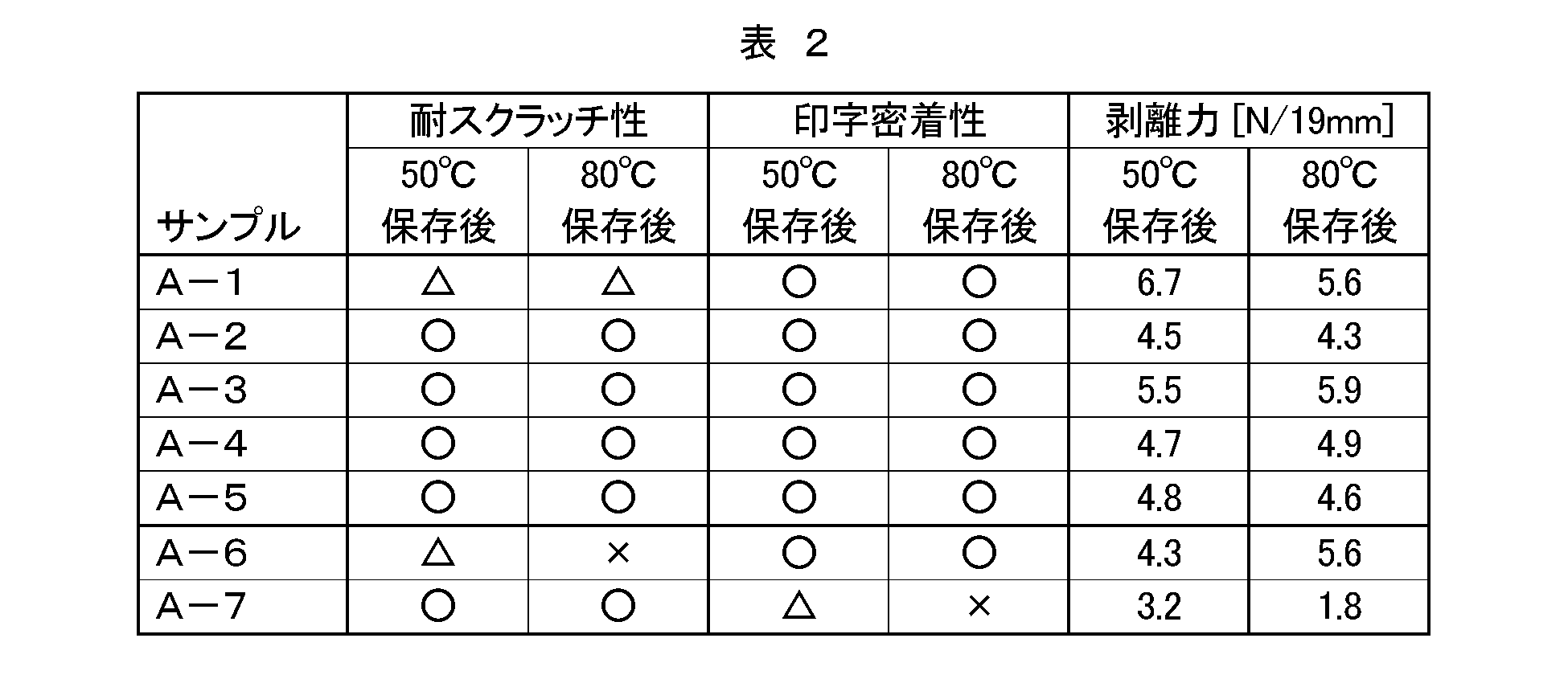
一方、摩擦係数変動率Δμが10%以上であるサンプルA-6では、50℃保存後の耐スクラッチ性は実用可能レベルであったが、80℃保存後の耐スクラッチ性に欠けるものであった。また、80℃保存後の摩擦係数μ80が0.4を超えて上昇した。摩擦係数μ80を0.4以下に抑えようとして滑剤L5の添加量を増したサンプルA-7では、摩擦係数変動率Δμがさらに大きくなり、耐スクラッチ性は向上したものの、印字密着性が不足した。また、保存後の剥離力が著しく低下し、粘着テープを用いた剥離作業に適さないものであった。
10:透明フィルム
12:基材層
14:背面層
20:粘着剤層
30:剥離ライナー
Claims (7)
- 透明な樹脂材料からなる基材層と、該基材層の第一面上に設けられた背面層と、を有する透明フィルムであって、
前記背面層の厚みが1μm以下であり、
温度50℃、相対湿度15%で3日間保存した後における前記背面層の摩擦係数μ50と、温度80℃、相対湿度80%で3日間保存した後における前記背面層の摩擦係数μ80とから、両摩擦係数の差の絶対値|μ80-μ50|を両摩擦係数のうち小さいほうの値で除して求められる摩擦係数変動率Δμが10%未満である、透明フィルム。 - 前記摩擦係数μ50およびμ80がいずれも0.4以下である、請求項1に記載の透明フィルム。
- 前記背面層は単層構造であって前記基材層上に直接設けられている、請求項1または2に記載の透明フィルム。
- 前記背面層は、滑剤を含む樹脂材料からなる、請求項1から3のいずれか一項に記載の透明フィルム。
- 前記滑剤は、前記背面層の樹脂成分と結合可能な官能基を有する反応性滑剤である、請求項4に記載の透明フィルム。
- 前記背面層は、帯電防止成分を含む樹脂材料からなる、請求項1から5のいずれか一項に記載の透明フィルム。
- 請求項1から6のいずれか一項に記載の透明フィルムと、
該透明フィルムの、前記背面層とは反対側の表面に設けられた粘着剤層と、
を備える、表面保護フィルム。
Priority Applications (3)
| Application Number | Priority Date | Filing Date | Title |
|---|---|---|---|
| US13/383,656 US9321247B2 (en) | 2009-07-15 | 2010-07-09 | Transparent film and use thereof |
| KR1020177006642A KR101741975B1 (ko) | 2009-07-15 | 2010-07-09 | 표면 보호 필름 |
| CN201080029912.1A CN102470644B (zh) | 2009-07-15 | 2010-07-09 | 透明膜及其利用 |
Applications Claiming Priority (2)
| Application Number | Priority Date | Filing Date | Title |
|---|---|---|---|
| JP2009167207A JP5534728B2 (ja) | 2009-07-15 | 2009-07-15 | 透明フィルムおよびその利用 |
| JP2009-167207 | 2009-07-15 |
Publications (1)
| Publication Number | Publication Date |
|---|---|
| WO2011007728A1 true WO2011007728A1 (ja) | 2011-01-20 |
Family
ID=43449336
Family Applications (1)
| Application Number | Title | Priority Date | Filing Date |
|---|---|---|---|
| PCT/JP2010/061694 Ceased WO2011007728A1 (ja) | 2009-07-15 | 2010-07-09 | 透明フィルムおよびその利用 |
Country Status (6)
| Country | Link |
|---|---|
| US (1) | US9321247B2 (ja) |
| JP (1) | JP5534728B2 (ja) |
| KR (2) | KR20120039713A (ja) |
| CN (1) | CN102470644B (ja) |
| TW (1) | TWI508857B (ja) |
| WO (1) | WO2011007728A1 (ja) |
Cited By (1)
| Publication number | Priority date | Publication date | Assignee | Title |
|---|---|---|---|---|
| CN104220516A (zh) * | 2012-04-13 | 2014-12-17 | Umgabs株式会社 | 润滑性热塑性树脂组合物及其成型品 |
Families Citing this family (16)
| Publication number | Priority date | Publication date | Assignee | Title |
|---|---|---|---|---|
| JP6230233B2 (ja) | 2012-04-23 | 2017-11-15 | 日東電工株式会社 | 表面保護フィルム |
| JP2014036011A (ja) * | 2012-08-10 | 2014-02-24 | Sumitomo Chemical Co Ltd | マスキングフィルム付き導光板原板 |
| JP6092035B2 (ja) | 2013-07-30 | 2017-03-08 | 日東電工株式会社 | 表面保護フィルムおよび光学部材 |
| JP6092034B2 (ja) | 2013-07-30 | 2017-03-08 | 日東電工株式会社 | 表面保護フィルムおよび光学部材 |
| JP6092033B2 (ja) | 2013-07-30 | 2017-03-08 | 日東電工株式会社 | 表面保護フィルムおよび光学部材 |
| JP6203563B2 (ja) * | 2013-07-31 | 2017-09-27 | 日東電工株式会社 | 粘着シート、及び、光学部材 |
| JP5950467B2 (ja) * | 2013-09-24 | 2016-07-13 | 信越化学工業株式会社 | ペリクル |
| JP6349126B2 (ja) * | 2014-03-31 | 2018-06-27 | 株式会社ダイセル | ペン入力デバイス用透明積層フィルム及びその製造方法 |
| CN113524702B (zh) * | 2016-02-08 | 2023-06-20 | 住友化学株式会社 | 层叠光学膜的制造方法 |
| WO2018199619A1 (ko) * | 2017-04-25 | 2018-11-01 | 주식회사 엘지화학 | 광학 디바이스 |
| JP2019020718A (ja) * | 2017-07-20 | 2019-02-07 | 住友化学株式会社 | 光学シート |
| JP2019069541A (ja) | 2017-10-06 | 2019-05-09 | 日東電工株式会社 | トップコート層付きフィルム、表面保護フィルムおよび光学部品 |
| JP7066869B2 (ja) * | 2018-09-28 | 2022-05-13 | 株式会社ユポ・コーポレーション | インモールドラベル及びインモールドラベル付き容器 |
| JP7406686B2 (ja) * | 2018-11-02 | 2023-12-28 | 日本ゼオン株式会社 | 容器 |
| CN111019553B (zh) * | 2019-12-30 | 2022-01-28 | 苏州赛伍应用技术股份有限公司 | 一种用于x射线医疗设备的反射膜及其制备方法和应用 |
| JP7822728B2 (ja) * | 2021-09-10 | 2026-03-03 | 日東電工株式会社 | 積層体、積層体付光学部材および画像表示装置 |
Citations (5)
| Publication number | Priority date | Publication date | Assignee | Title |
|---|---|---|---|---|
| JPH0726223A (ja) * | 1993-07-08 | 1995-01-27 | Dainippon Printing Co Ltd | 帯電防止性を有する微粘着高透明保護フィルム |
| JP2003080639A (ja) * | 2001-09-11 | 2003-03-19 | Mitsubishi Polyester Film Copp | フィルム |
| JP2003121606A (ja) * | 2001-08-07 | 2003-04-23 | Fuji Photo Film Co Ltd | 反射防止フィルム、偏光板、および画像表示装置 |
| JP2003320631A (ja) * | 2002-05-08 | 2003-11-11 | Fujimori Kogyo Co Ltd | 表面保護フィルムおよびそれを用いた積層体 |
| JP2007283665A (ja) * | 2006-04-18 | 2007-11-01 | Mitsubishi Rayon Co Ltd | 熱成形用艶消しアクリル樹脂フィルム状物、熱成形用艶消しアクリル樹脂フィルム状物の製造方法、および、この熱成形用艶消しアクリル樹脂フィルム状物を含む積層体 |
Family Cites Families (14)
| Publication number | Priority date | Publication date | Assignee | Title |
|---|---|---|---|---|
| ID23862A (id) | 1998-02-20 | 2000-05-25 | Scil Diagnotics Gmbh | Sistem analisis |
| US6950236B2 (en) | 2001-04-10 | 2005-09-27 | Fuji Photo Film Co., Ltd. | Antireflection film, polarizing plate, and apparatus for displaying an image |
| WO2003011958A1 (en) * | 2001-08-02 | 2003-02-13 | 3M Innovative Properties Company | Optically clear and antistatic pressure sensitive adhesives |
| JP2004223714A (ja) * | 2001-11-27 | 2004-08-12 | Toyobo Co Ltd | 白色積層ポリエステルフィルム |
| JP2003334911A (ja) | 2002-05-21 | 2003-11-25 | Mitsubishi Polyester Film Copp | ディスプレイ表面保護フィルム |
| KR101202085B1 (ko) | 2003-12-12 | 2012-11-15 | 도요보 가부시키가이샤 | 열 수축성 필름 |
| JP4390046B2 (ja) | 2003-12-12 | 2009-12-24 | 東洋紡績株式会社 | ポリエステル系熱収縮性フィルム |
| JP2005314563A (ja) | 2004-04-28 | 2005-11-10 | Jsr Corp | 帯電防止フィルム |
| JP2011148943A (ja) | 2010-01-25 | 2011-08-04 | Nitto Denko Corp | 保護シートおよびその利用 |
| JP2011168751A (ja) | 2010-02-22 | 2011-09-01 | Nitto Denko Corp | 表面保護フィルム |
| JP2011178879A (ja) | 2010-03-01 | 2011-09-15 | Nitto Denko Corp | 保護シートおよびその利用 |
| TW201134911A (en) | 2010-03-03 | 2011-10-16 | Nitto Denko Corp | Protective sheet and use thereof |
| JP5483713B2 (ja) | 2010-05-12 | 2014-05-07 | 日東電工株式会社 | 表面保護フィルム |
| JP2012072206A (ja) | 2010-09-27 | 2012-04-12 | Nitto Denko Corp | 表面保護シート |
-
2009
- 2009-07-15 JP JP2009167207A patent/JP5534728B2/ja not_active Expired - Fee Related
-
2010
- 2010-07-09 US US13/383,656 patent/US9321247B2/en not_active Expired - Fee Related
- 2010-07-09 KR KR1020127003830A patent/KR20120039713A/ko not_active Ceased
- 2010-07-09 KR KR1020177006642A patent/KR101741975B1/ko not_active Expired - Fee Related
- 2010-07-09 CN CN201080029912.1A patent/CN102470644B/zh active Active
- 2010-07-09 WO PCT/JP2010/061694 patent/WO2011007728A1/ja not_active Ceased
- 2010-07-14 TW TW099123173A patent/TWI508857B/zh not_active IP Right Cessation
Patent Citations (5)
| Publication number | Priority date | Publication date | Assignee | Title |
|---|---|---|---|---|
| JPH0726223A (ja) * | 1993-07-08 | 1995-01-27 | Dainippon Printing Co Ltd | 帯電防止性を有する微粘着高透明保護フィルム |
| JP2003121606A (ja) * | 2001-08-07 | 2003-04-23 | Fuji Photo Film Co Ltd | 反射防止フィルム、偏光板、および画像表示装置 |
| JP2003080639A (ja) * | 2001-09-11 | 2003-03-19 | Mitsubishi Polyester Film Copp | フィルム |
| JP2003320631A (ja) * | 2002-05-08 | 2003-11-11 | Fujimori Kogyo Co Ltd | 表面保護フィルムおよびそれを用いた積層体 |
| JP2007283665A (ja) * | 2006-04-18 | 2007-11-01 | Mitsubishi Rayon Co Ltd | 熱成形用艶消しアクリル樹脂フィルム状物、熱成形用艶消しアクリル樹脂フィルム状物の製造方法、および、この熱成形用艶消しアクリル樹脂フィルム状物を含む積層体 |
Cited By (2)
| Publication number | Priority date | Publication date | Assignee | Title |
|---|---|---|---|---|
| CN104220516A (zh) * | 2012-04-13 | 2014-12-17 | Umgabs株式会社 | 润滑性热塑性树脂组合物及其成型品 |
| CN104220516B (zh) * | 2012-04-13 | 2016-08-31 | Umgabs株式会社 | 润滑性热塑性树脂组合物及其成型品 |
Also Published As
| Publication number | Publication date |
|---|---|
| US9321247B2 (en) | 2016-04-26 |
| KR20170031261A (ko) | 2017-03-20 |
| KR20120039713A (ko) | 2012-04-25 |
| JP5534728B2 (ja) | 2014-07-02 |
| US20120231265A1 (en) | 2012-09-13 |
| CN102470644B (zh) | 2015-07-29 |
| TW201116407A (en) | 2011-05-16 |
| JP2011020348A (ja) | 2011-02-03 |
| CN102470644A (zh) | 2012-05-23 |
| TWI508857B (zh) | 2015-11-21 |
| KR101741975B1 (ko) | 2017-05-30 |
Similar Documents
| Publication | Publication Date | Title |
|---|---|---|
| JP5534728B2 (ja) | 透明フィルムおよびその利用 | |
| JP5406615B2 (ja) | 透明フィルムおよび該フィルムを用いた表面保護フィルム | |
| JP5721448B2 (ja) | 透明フィルムおよびその利用 | |
| JP2015044970A (ja) | 表面保護フィルム及び光学部材 | |
| JP2015027764A (ja) | 表面保護フィルムおよび光学部材 | |
| CN113784850A (zh) | 转印片及其制造方法、使用了该转印片的成型体的制造方法及成型体、使用了该成型体的前面板以及图像显示装置 | |
| JP5721805B2 (ja) | 透明フィルムおよび該フィルムを用いた表面保護フィルム | |
| KR20240011799A (ko) | 하드 코트 필름, 광학 부재, 및 화상 표시 장치 | |
| JP7166056B2 (ja) | ハードコートフィルムの製造方法 | |
| WO2019146622A1 (ja) | ハードコートフィルム及びその製造方法 | |
| JP7166057B2 (ja) | ハードコートフィルムの製造方法 | |
| JP7154680B2 (ja) | ハードコートフィルムの製造方法 | |
| JP7154681B2 (ja) | ハードコートフィルムの製造方法 | |
| TW202606883A (zh) | 表面保護膜、光學部件及電子裝置 | |
| JP2025151076A (ja) | 表面保護フィルム、光学部品および電子装置 |
Legal Events
| Date | Code | Title | Description |
|---|---|---|---|
| WWE | Wipo information: entry into national phase |
Ref document number: 201080029912.1 Country of ref document: CN |
|
| 121 | Ep: the epo has been informed by wipo that ep was designated in this application |
Ref document number: 10799786 Country of ref document: EP Kind code of ref document: A1 |
|
| NENP | Non-entry into the national phase |
Ref country code: DE |
|
| ENP | Entry into the national phase |
Ref document number: 20127003830 Country of ref document: KR Kind code of ref document: A |
|
| WWE | Wipo information: entry into national phase |
Ref document number: 13383656 Country of ref document: US |
|
| 122 | Ep: pct application non-entry in european phase |
Ref document number: 10799786 Country of ref document: EP Kind code of ref document: A1 |