WO2011007476A1 - 基板の加工装置および基板の加工方法、並びに加工基板の製造方法 - Google Patents
基板の加工装置および基板の加工方法、並びに加工基板の製造方法 Download PDFInfo
- Publication number
- WO2011007476A1 WO2011007476A1 PCT/JP2010/002197 JP2010002197W WO2011007476A1 WO 2011007476 A1 WO2011007476 A1 WO 2011007476A1 JP 2010002197 W JP2010002197 W JP 2010002197W WO 2011007476 A1 WO2011007476 A1 WO 2011007476A1
- Authority
- WO
- WIPO (PCT)
- Prior art keywords
- substrate
- processing
- abrasive grains
- glass substrate
- angle
- Prior art date
- Legal status (The legal status is an assumption and is not a legal conclusion. Google has not performed a legal analysis and makes no representation as to the accuracy of the status listed.)
- Ceased
Links
Images






Classifications
-
- B—PERFORMING OPERATIONS; TRANSPORTING
- B24—GRINDING; POLISHING
- B24C—ABRASIVE OR RELATED BLASTING WITH PARTICULATE MATERIAL
- B24C1/00—Methods for use of abrasive blasting for producing particular effects; Use of auxiliary equipment in connection with such methods
- B24C1/04—Methods for use of abrasive blasting for producing particular effects; Use of auxiliary equipment in connection with such methods for treating only selected parts of a surface, e.g. for carving stone or glass
-
- B—PERFORMING OPERATIONS; TRANSPORTING
- B24—GRINDING; POLISHING
- B24C—ABRASIVE OR RELATED BLASTING WITH PARTICULATE MATERIAL
- B24C3/00—Abrasive blasting machines or devices; Plants
- B24C3/02—Abrasive blasting machines or devices; Plants characterised by the arrangement of the component assemblies with respect to each other
-
- B—PERFORMING OPERATIONS; TRANSPORTING
- B24—GRINDING; POLISHING
- B24C—ABRASIVE OR RELATED BLASTING WITH PARTICULATE MATERIAL
- B24C3/00—Abrasive blasting machines or devices; Plants
- B24C3/02—Abrasive blasting machines or devices; Plants characterised by the arrangement of the component assemblies with respect to each other
- B24C3/04—Abrasive blasting machines or devices; Plants characterised by the arrangement of the component assemblies with respect to each other stationary
Definitions
- the present invention relates to a substrate processing apparatus, a substrate processing method, and a processed substrate manufacturing method. More specifically, the substrate surface after processing can be made smooth (mirror surface) and is simple, a substrate processing device, a substrate processing method using the processing device, and a processed substrate using the processing method It is related with the manufacturing method.
- the defect of a glass substrate means internal defects, such as an internal bubble and an internal foreign material, and surface defects, such as a permite
- display defects such as bright spots and black spots occur in the vicinity of the defects.
- an internal bubble having a certain size for example, a diameter of 100 ⁇ m or more
- the vicinity thereof is observed as a bright spot.
- the mechanism by which the bright bubbles are generated by the internal bubbles is not necessarily clear, but the presence of the internal bubbles may cause the lens effect due to the glass around the internal bubbles and the disorder of the polarization state due to the stress remaining on the glass around the internal bubbles. It is thought to be the cause.
- black spots may be generated when the internal foreign matter is made of a light-shielding material.
- the glass substrate has as few defects as possible.
- Internal bubbles are generated when bubbles are formed in the melted glass raw material due to entrainment of air, release of gas from the refractory material, or the like in the process of melting the glass raw material when manufacturing the glass substrate. Furthermore, depending on the glass raw material used, there is a glass raw material itself that generates gas. Such internal bubbles exist with a certain probability depending on the volume, and it is not easy to reduce the probability. In addition, when the position of the bubble which exists in a glass substrate is near the surface, a permite
- the protrusion formed on the surface of the glass substrate is a surface defect caused by internal bubbles or internal foreign matter as described above.
- scratches formed on the surface of the glass substrate are caused by the glass substrates coming into contact with each other in a step of cutting out the glass substrate from a large glass plate called an original plate and performing peripheral processing.
- the conventional substrate processing method has a problem that it is difficult to correct a defect of the substrate.
- Such a requirement is common to general substrates such as glass substrates constituting flat display panels such as liquid crystal display panels and plasma display panels.
- glass for liquid crystal display panels is particularly used for the following reasons. This is noticeable in the substrate.
- the semiconductor element is easily affected by alkali metals. Therefore, it is common to use an alkali-free glass that does not contain an alkali metal as an additive component (the alkali metal as an impurity is 1% or less) as a glass substrate for a liquid crystal display panel.
- the alkali-free glass has a high melting point, the alkali-free glass is difficult to remove bubbles when the glass raw material is melted, and internal bubbles are likely to remain. Therefore, since the glass substrate for liquid crystal display panels tends to include defects as internal bubbles, there is a particularly high demand for a technique for improving the quality of the substrate by correcting the defects.
- At least one of powder or fluid is sprayed onto a portion where the defect to be corrected formed on the substrate is located, and an area including at least the defect to be corrected from the substrate.
- the technique for performing the brittle processing has a problem that the processed substrate surface cannot be smoothed.
- the present invention has been made in view of the above problems, and an object of the present invention is to use a substrate processing apparatus that can smooth a substrate surface after processing and is simple, and the processing apparatus.
- An object of the present invention is to provide a method for processing a substrate and a method for manufacturing a processed substrate using the processing method.
- the substrate processing apparatus of the present invention is provided on the substrate on which the abrasive grain injection member is arranged so that the abrasive injection angle with respect to the processed surface of the substrate becomes an angle in brittle processing.
- the angle of entry of the abrasive grains into the processing surface of the substrate is changed from the angle in the brittle processing to the ductile processing between the spray member and the processing surface of the substrate in the spray direction of the abrasive grains.
- An injection direction changing member for changing to an angle is arranged, and the injection direction changing member is movable.
- the said injection direction change member is arrange
- the approach angle can be changed from an angle in brittle processing to an angle in ductile processing.
- the processed substrate surface can be smoothed.
- the injection direction changing member is movable, the angle of entry of the abrasive grains into the processing surface of the substrate is changed again from the angle in ductile processing to the angle in brittle processing. Can do.
- the injection direction changing member moves to a position where it does not come into contact with the abrasive grains, so that the angle of entry of the abrasive grains into the processing surface of the substrate is changed again from the angle in ductile processing to the angle in brittle processing. be able to.
- substrate can be changed from the angle in a brittle process to the angle in a ductile process using only one injection member, and also ductility. Since the angle in processing can be changed to the angle in brittle processing, the substrate processing apparatus can be simplified.
- the substrate processing apparatus of the present invention is a substrate processing apparatus in which the abrasive grain spraying member is disposed so that the abrasive grain spraying angle with respect to the substrate processing surface is an angle in brittle processing. Then, the angle of entry of the abrasive grains into the processed surface of the substrate is changed from the angle in the brittle processing to the angle in ductile processing between the spray member in the spray direction of the abrasive grains and the processed surface of the substrate.
- the injection direction change member for this is arrange
- the substrate processing apparatus of the present invention has an effect that the processed substrate surface can be smoothed and has a simple structure.
- Embodiment 1 The first embodiment of the present invention will be described as follows. Note that the present invention is not limited to this, and the dimensions, materials, shapes, relative arrangements, and the like of the component parts described in this embodiment are not particularly limited unless otherwise specified. It is not intended to limit the scope to that, but merely an illustrative example. In this specification and the like, “A to B” indicating a range indicates “A or more and B or less”.
- a glass substrate defect correcting device and a defect correcting method will be described as examples in the substrate processing apparatus and processing method.
- the present invention is not limited to these, and can also be applied to a general substrate (material) processing apparatus and processing method.
- the substrate (material) that is the object to be processed is not particularly limited as long as it is a brittle material, and examples thereof include glass and ceramics.
- the defect correction method of this embodiment is a glass substrate defect correction method for constituting a display panel, and the defect to be corrected is an internal defect formed on the glass substrate.
- defect correction method of the present embodiment can be applied to glass substrates for constituting various display panels such as a liquid crystal display panel and a plasma display panel (PDP).
- various display panels such as a liquid crystal display panel and a plasma display panel (PDP).
- PDP plasma display panel
- the defect correction method of the present embodiment can be carried out at various stages in the production of glass substrates and display panels. For example, a stage in which a glass manufacturer cuts a glass substrate from the original plate and ships it; a stage in which the display substrate manufacturer accepts the glass substrate and then uses it for a display panel; Thereafter, the defect correction method of this embodiment can be performed in various stages such as a stage until the display device is assembled.
- the defect correction method of the present embodiment forms the glass substrate manufacturing method. It will be.
- the glass substrate is for a liquid crystal display panel
- the stage from the inspection of the configured display panel to the assembly as a display device is assumed as an implementation stage of the defect correction method.
- internal bubbles as internal defects, a method for correcting internal bubbles will be described.
- the defect correcting method of the present embodiment is particularly effective for a glass substrate for constituting a liquid crystal display panel.
- FIG. 2 is a cross-sectional view of the glass substrate 1 on which internal bubbles 1b as internal defects to be corrected are formed.
- the internal bubble 1b may not be accompanied by the protrusion 1p depending on its size and position.
- the internal bubbles 1b may have various sizes from those having a maximum diameter of 100 ⁇ m or less to those having the same thickness as the glass substrate 1 (for example, 0.7 mm). For the small internal bubbles 1b having a maximum diameter of, for example, 100 ⁇ m or less, since the adverse effect on the display is small, it may be considered that no special measures are taken. Further, for the internal bubbles 1b having a maximum diameter of, for example, 100 to 300 ⁇ m, it may be considered to take a measure such as blackening. However, for the internal bubbles 1b whose maximum diameter exceeds, for example, 300 ⁇ m, it is difficult to consider an effective measure for sufficiently reducing the adverse effect on the display, except for the defect correction method of the present embodiment described below.
- the defect correcting method according to the present embodiment can deal with a wide range of internal bubbles 1b from small to large, but is particularly effective for large internal bubbles 1b for which it is difficult to consider other effective measures.
- the abrasive grains are sprayed at a position where the internal bubble 1b, which is an internal defect formed in the glass substrate 1, is located, and at least the internal portion from the surface 1s of the glass substrate 1.
- the glass material is removed until the bubbles 1b are reached.
- the glass material 1d surrounding the internal bubble 1b (hereinafter referred to as a winding part) 1d may cause a lens effect or a disorder of the polarization state, and therefore, it is removed together with the internal bubble 1b. preferable.
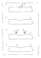
- FIGS. 1A to 1E are diagrams showing a process of removing internal defects by the defect correction method of this embodiment.
- abrasive grains 12a are sprayed at a predetermined spraying speed onto the protrusions 1p on the surface 1s of the glass substrate 1.
- alumina having a particle size of 800 (about 0.03 mm (30 ⁇ m)) is used as the abrasive grains 12 a, but is not limited to this, and is appropriately selected according to the type of the substrate to be processed. be able to.
- the abrasive grains 12a include alumina and cerium.
- an alumina as the abrasive grain 12a.
- the grain size of the abrasive grains 12a is preferably 0.1 to 100 ⁇ m.
- the particle size of the abrasive grains 12a may be changed between brittle processing and ductile processing. In this case, at the time of brittle processing, the particle size of the abrasive grains 12a is increased to increase the processing force, while at the time of ductile processing, the particle size of the abrasive grains 12a is decreased to decrease the processing force.
- the scanning speed (moving speed of the correction head 12) is set to 0.2 mm / s to 0.6 mm / s, but is not limited to this, and is appropriately determined according to the type of the substrate to be processed. Can be selected.
- the injection amount (injection pressure) of the abrasive grains 12a is injected with 0.8 MPa of air, but is not limited to this, and can be appropriately selected according to the type of the substrate to be processed.
- the spraying time of the abrasive grains 12a is not particularly limited, and can be appropriately selected according to the type of the substrate to be processed, the depth of the substrate to be processed, and the like.
- the abrasive grains 12a are continuously sprayed at the above injection speed, and the glass material of the protrusions 1p is removed by the abrasive grains 12a until the abrasive grains 12a reach the internal bubbles 1b as shown in FIG. . And the grinding area
- 1A to 1C are diagrams for explaining brittle processing. Further, as shown in FIG.
- FIG. 1D and FIG. 1E are diagrams for explaining ductility processing.
- the approach angle of the abrasive grains in the brittle processing is larger than 35 ° and within a range of 90 ° or less with respect to the surface 1s of the substrate 1.
- the substrate is a glass substrate, it is preferably 90 °.
- the approach angle of the abrasive grains in the ductile processing is larger than 0 ° and within a range of 35 ° or less with respect to the surface 1s of the substrate 1.
- the substrate is a glass substrate, it is preferably 30 °.
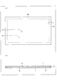
- FIG. 3A is a cross-sectional view of the defect correction apparatus 10 for performing the defect correction method of the present embodiment.
- the defect correcting device 10 is fixed to the substrate mounting table 13 and a substrate mounting table 13 for fixing the glass substrate 1 as a correction target in a direction perpendicular to the ground on the mounting surface 11 a of the mounting table 11.
- a reflecting plate mounting base 15 on which a rotating member 16 having a jetting direction changing member 19 provided with a fixing member 17 is mounted is provided.
- the reflector 18 preferably contains ceramic, and more preferably consists of ceramic only.
- the ceramic include silicon carbide (SiC) and silicon nitride (SiN).
- the material of the reflecting plate support member 17 is not specifically limited, For example, a metal etc. are mentioned.
- the size of the reflector 18 is not particularly limited, but the area is preferably 1 cm square or more.
- the rotating member 16 rotates the reflecting plate 18 around the injection direction of the abrasive grains 12a injected from the correction head 12 (the normal direction from the processing surface of the glass substrate 1 passing through the reflecting plate 18). Is.
- the correction head 12 is provided on the head mounting base 14 so as to be movable in a horizontal direction and a vertical direction with respect to the ground, and the spraying direction of the abrasive grains 12a is horizontal with respect to the ground (with respect to the glass substrate 1). Vertical direction).
- the correction head 12 includes an injection nozzle (described later) for injecting abrasive grains 12a for grinding the glass substrate 1. That is, the defect correction apparatus 10 moves the correction head 12 to a position facing the internal bubble 1b or the reflection plate 18 of the glass substrate 1, and the abrasive grains 12a are moved to the surface 1s of the glass substrate 1 or the surface of the reflection plate 18 at that position. It is designed to be sprayed into the grinding process.
- the abrasive grains 12 a do not contact (collision) the reflecting plate 18 and the glass substrate 1.
- the surface is sprayed onto the surface 1s to perform grinding.
- grinding is performed by spraying the abrasive grains 12a onto the surface of the reflecting plate 18 (in the case of ductility processing)
- the abrasive grains 12a contacting (collising) with the reflecting plate 18 are reflected in the direction of the glass substrate 1.
- grinding is performed by spraying onto the surface 1s of the glass substrate 1 at a shallow angle.
- the ejection direction changing member 19 is provided so as to be movable in the horizontal direction along with the circular surface (rotating surface) of the rotating member 16 in the reflecting plate mounting base 15 together with the rotating member 16.
- the injection direction changing member 19 moves to a position where it does not come into contact with the abrasive grains 12a ejected from the correction head 12 during brittle machining, and moves to a position where it comes into contact with the abrasive grains 12a ejected from the correction head 12 during ductility machining.
- the direction of the abrasive grains 12a sprayed is changed.
- the mounting table 11 is also movably provided, and the spray position of the abrasive grains 12a may be adjusted by moving the glass substrate 1 on the mounting table 11.
- the reflecting plate R (not shown) on the glass substrate 1 is provided.
- the abrasive grains 12a are sprayed toward the reflector R at a shallow angle, and the abrasive grains 12a that contact (impact) the reflector R reflect in the direction in which the reflector R is not provided on the glass substrate 1.
- grinding may be performed by spraying the surface 1 s of the glass substrate 1 at a shallow angle.
- the inclination angle of the reflecting plate R is adjusted in consideration of the spray position of the abrasive grains 12a on the glass substrate 1.
- the material of the reflector R is the same as that of the reflector 18. Moreover, the area, height, etc. of this reflector R are not specifically limited.
- FIG. 3B is a plan view showing a main part of the defect correcting apparatus 10 for performing the defect correcting method of the present embodiment. Specifically, it is a plan view showing a configuration excluding the substrate mounting table 13, the glass substrate 1, and the mounting table 11 when the defect correction apparatus 10 is viewed from the substrate mounting table 13 side. As shown in FIG. 3B, the rotating member 16 is rotated by the rotating shaft 25 in the reflecting plate mounting base 15. As a result, the defect correcting device 10 can change the injection position (injection direction) of the abrasive grains 12a.
- FIG. 3C is a cross-sectional view showing the main part of the defect correcting apparatus 10 for carrying out the defect correcting method of the present embodiment. Specifically, it is a cross-sectional view showing the configuration of the injection direction changing member 19.
- the reflection plate control member 27 in the reflection plate support member 17 causes the reflection plate 18 to pass through the injection direction of the abrasive grains 12 a (from the processed surface of the glass substrate 1 passing through the reflection plate 18).
- the angle of the abrasive grains 12a with respect to the (normal direction) can be changed.
- the defect correction apparatus 10 can change the spray position of the abrasive grains 12a (the spray position in the depth direction in the grinding region).
- a liquid crystal display panel is produced using the glass substrate 1 before defect correction. And when irradiating uniform light from the back surface of the created liquid crystal display panel, inspecting whether bright spots are observed due to the internal bubbles 1b formed on the glass substrate 1, and observed The position is specified in advance. Thereafter, the liquid crystal display panel is fixed to the substrate mounting table 13 of the defect correcting apparatus 10, and grinding processing described later is performed at the specified position.
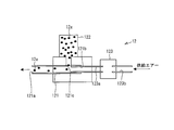
- FIG. 4 is a schematic diagram of the correction head 12 provided in the defect correction apparatus 10.
- the correction head 12 has a structure having an abrasive supply nozzle 121 for supplying a fixed amount of abrasive grains 12a.
- the abrasive grain supply nozzle 121 is made of a cylinder, a cylindrical front end hole 121a serving as a discharge hole for the abrasive grains 12a, a cylindrical rear end hole 121b serving as an air supply hole, and the cylindrical front end hole 121a and the cylindrical rear end hole 121b. And an abrasive grain supply hole 121c serving as a supply hole for the abrasive grains 12a.
- the abrasive grain supply hole 121c of the abrasive grain supply nozzle 121 is connected to an abrasive tank 122 for storing abrasive grains, and the cylindrical rear end hole 121b is connected to a high-speed solenoid valve 123.
- the abrasive grain tank 122 is provided with an opening / closing lid (not shown) at a connection portion with the abrasive grain supply nozzle 121, and the opening / closing lid is opened only when the abrasive grains 12a are supplied. .
- the high-speed solenoid valve 123 includes a connection cylinder 123a connected to the cylindrical rear end hole 121b of the abrasive grain supply nozzle 121 and an air intake port for taking in supply air from an air supply unit (not shown).
- an air supply unit not shown.
- the high-speed solenoid valve 123 is open, the supply air taken in from the air intake port 123b is supplied to the connecting cylinder 123a.
- the high-speed solenoid valve 123 is closed, the air intake Supplying supply air taken in from the port 123b to the connecting cylinder 123a is stopped.
- the abrasive grains 12a are ejected from the abrasive supply nozzle 121 by the supply air. Is done. If the high-speed solenoid valve 123 is in the closed state, the abrasive grains 12 a are not injected from the abrasive grain supply nozzle 121 regardless of the open / closed state of the opening / closing lid of the abrasive tank 122.
- the high-speed solenoid valve 123 is open and the opening / closing lid of the abrasive tank 122 is closed, only air that does not contain the abrasive grains 12a can be injected from the abrasive supply nozzle 121. it can.
- the correction head 12 having the above-described configuration is provided with, for example, abrasive grains 12a made of alumina having a particle size of 800 on the projection 1p on the surface 1s of the glass substrate 1 or a reflecting plate at a processing speed of 0.2 mm / s to 0.6 mm / s.
- abrasive grains 12a made of alumina having a particle size of 800 on the projection 1p on the surface 1s of the glass substrate 1 or a reflecting plate at a processing speed of 0.2 mm / s to 0.6 mm / s.
- the abrasive grains 12 a are continuously sprayed from the correction head 12 onto the surface 1 a of the glass substrate 1 or the surface of the reflector, the abrasive grains 12 a remain on the ground portion of the glass substrate 1. In such a case, the newly-injected abrasive grains 12a collide with the abrasive grains 12a remaining in the grinding site and cannot be directly ground on the actual grinding target surface, resulting in a problem of reduced grinding efficiency. .
- the abrasive grains 12a remaining at the grinding site can be removed by injection of only air. Can do. Thereby, it becomes possible to improve the grinding efficiency.
- the high-speed solenoid valve 123 is opened and the lid of the abrasive tank 122 is opened and closed intermittently, the air containing the abrasive grains 12a and Air that does not include the abrasive grains 12a can be alternately injected.
- AJM ABRASIVE Jet Machining
- removal processing up to the state shown in FIG. 1 (e) may be performed.
- the state shown in (e) of FIG. 1 is not necessarily an ideal state as the shape of the glass substrate 1, but as a result of actually confirming the influence on the display, it is compared with the state before the removal processing. Thus, the bright spots due to the internal bubbles 1b are hardly observed.
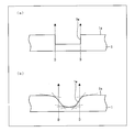
- FIG. 5 (a) when a recess having a shape in which a part of the processed surface 1w is vertically formed with respect to the surface 1s is formed, the processed surface is observed in the observation direction D perpendicular to the surface 1s. Since the vertical portion 1w coincides with the observation direction D, the influence on the display of the processed surface 1w is accumulated in the observation direction D. As a result, the processed surface 1w is easily noticeable.
- the processing surface 1w does not stand perpendicular to the surface 1s as described above, and a tangential plane at an arbitrary position of the processing surface 1w (( b)) is parallel or inclined with respect to the surface 1s, the influence on the display of the processed surface 1w is not accumulated in the observation direction D, and the processed surface 1w is conspicuous. Can be difficult.
- the spraying speed of the abrasive grains 12a sprayed from the correction head 12 may be changed depending on the defect position. For example, when trying to obtain a recess having a shape as shown in FIG. 5B, the spraying speed of the abrasive grains 12a is increased at the center of the recess, and the abrasive is directed outward from the center of the recess. What is necessary is just to slow down the injection speed of the grain 12a gradually.
- the refractive index change in the depression can be reduced as compared with an empty state in the depression.
- the dent can be made inconspicuous.
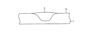
- a liquid transparent resin may be filled into the hollow and solidified.
- alumina is used as the abrasive grains 12a, but the present invention is not limited to this, and silicon carbide, boron carbide, cerium oxide, or the like may be used.
- the grain size of the abrasive grains 12a is not limited to 800, but may be other grain sizes, more preferably after finishing with 800 and finishing with 2000, and may be changed according to the object to be ground. .
- the glass substrate 1 on which the internal bubbles 1b as internal defects are formed As shown in FIG. 7, the glass substrate 1 on which the internal foreign matter 1c as internal defects is formed. May be the correction target. Even in this case, it is possible to reduce the lens effect and polarization state disturbance described above. Further, in the case where the internal foreign matter 1c is made of a light-shielding material, an effect of removing black spots can be obtained by performing processing that completely removes the internal foreign matter 1c.
- the defect correction method of this embodiment is a glass substrate defect correction method for constituting a display panel, and the defect to be corrected is a protrusion as a surface defect formed on the glass substrate. As described in the first embodiment, this protrusion may be formed due to the presence of an internal defect, but may be formed independently of the internal defect.
- the defect correcting method of the present embodiment can be applied to glass substrates for constituting various display panels such as a liquid crystal display panel and a plasma display panel (PDP), as in the case of the first embodiment.
- various display panels such as a liquid crystal display panel and a plasma display panel (PDP), as in the case of the first embodiment.
- PDP plasma display panel
- defect correction method of the present embodiment can be carried out at various stages in the production of the glass substrate and the display panel as in the case of the first embodiment.
- FIG. 8 is a cross-sectional view of the glass substrate 1 on which protrusions 1p as surface defects to be corrected are formed.
- the defect correcting apparatus 10 described in the first embodiment can be used.
- FIGS. 9A to 9C are diagrams for explaining brittle processing. Furthermore, as shown in FIG.
- FIG. 9 (d) the abrasive grains 12a are continuously injected at the above-described injection speed at a shallower angle than the case shown in FIG. 9 (b). In this state, the abrasive grains 12a are further sprayed, and the glass material is completely removed until the correction surface 1f becomes smooth (mirror surface) as shown in FIG. 9 (e).
- FIG. 9D and FIG. 9E are diagrams for explaining ductility processing.
- removal processing up to the state of FIG. 9 (e) may be performed.
- the height of the protrusion 1p is lowered by removing a part or all of the protrusion 1p, and this is referred to as flattening of the protrusion 1p.
- the surface 1s on which the protrusion 1p is formed can be brought close to the original surface shape. As a result, it is possible to make it difficult to generate a bright spot due to the protrusion 1p.
- alumina having a particle size of 800 is used and injected at a processing speed of 0.2 mm / s to 0.6 mm / s (injection speed of 150 to 200 m / s). You may make it do, and you may change the material of the abrasive grain 12a, a particle size, and an injection speed as needed.
- the defect to be corrected for the glass substrate 1 is the protrusion 1p.
- the defect to be corrected for the glass substrate 1 is a surface scratch. An example will be described.
- the defect correction method of the present embodiment is a glass substrate defect correction method for constituting a display panel, and the defect to be corrected is a scratch as a surface defect formed on the glass substrate.
- the defect correcting method of the present embodiment can be applied to glass substrates for constituting various display panels such as a liquid crystal display panel and a plasma display panel (PDP), as in the case of the first embodiment.
- various display panels such as a liquid crystal display panel and a plasma display panel (PDP), as in the case of the first embodiment.
- PDP plasma display panel
- defect correction method of the present embodiment can be carried out at various stages in the production of the glass substrate and the display panel as in the case of the first embodiment.
- FIG. 10 is a cross-sectional view of the glass substrate 1 on which scratches 1v as surface defects to be corrected are formed.
- the defect correcting apparatus 10 described in the first embodiment can be used.
- FIG. 11 are diagrams showing the progress of the grinding process.
- the abrasive grains 12 a are ejected by the correction head 12, as shown in FIG. 11A, the ground abrasive 12 a comes into contact with the surface 1 s of the glass substrate 1 to start grinding. Then, the abrasive grains 12a are ejected while the correction head 12 is swung in the horizontal direction, thereby forming a scratch 1v on the original surface 1s of the glass substrate 1 as shown in FIG. The angle formed by the surface can be reduced.
- FIG. 11 and (b) of FIG. 11 are figures explaining brittle processing. Further, as shown in FIG.
- the abrasive grains 12a are continuously injected at the above-described injection speed at a shallower angle than the case shown in FIG. In this state, the abrasive grains 12a are continuously sprayed, and as shown in FIG. 11D, the angle formed by the surface formed by the scratches 1v is made until the correction surface 1f becomes smooth (mirror surface). Make it smaller.
- FIG. 11 and (d) in FIG. 11 are diagrams for explaining ductility processing.
- the angle formed by the surface formed by the scratch 1v with respect to the original surface 1s of the glass substrate 1 is reduced, and this is smoothed. Called.
- the surface 1s on which the scratch 1v is formed can be brought close to the original surface shape. As a result, it is possible to make it difficult to generate a bright spot due to the scratch 1v.
- the tangent plane at an arbitrary position of the processed surface 1w is the surface 1s. It is desirable to be parallel or inclined with respect to. Moreover, as shown in FIG. 6 in Embodiment 1, it is desirable to fill the formed recess with the transparent material 2.
- FIG. 12A is a plan view showing a liquid crystal display panel according to an embodiment of the present invention
- FIG. 12B is a cross-sectional view showing the liquid crystal display panel.
- the liquid crystal display panel 20 is configured by two glass substrates 1 facing each other at a predetermined interval and sealing the periphery with a liquid crystal 21 sandwiched therebetween. Although not shown, a polarizing plate or the like is attached to the outer surfaces of the two glass substrates 1.
- the two glass substrates 1 have a processed surface 1w on the surface in the display area 20a of the liquid crystal display panel 20 on which the glass material removal processing described in the first to third embodiments is performed.
- this processed surface 1w may have both of the two glass substrates 1, and may have either one.
- the processed surface 1w is preferably filled with a transparent material.
- the glass material removal processing described in the first to third embodiments is applied to the internal defects and surface defects originally formed on the two glass substrates 1, and as a result, The adverse effect is reduced, and the liquid crystal display panel 20 that had to be handled as a defective product in the past can also be made non-defective.
- the defect correcting apparatus in which the correction head 12 is installed so that the injection direction of the abrasive grains 12a is horizontal with respect to the ground is not limited to this.
- the spray direction of the abrasive grains 12a is perpendicular to the ground (perpendicular to the glass substrate 1). It is also possible to use the defect correction apparatus 110 in which the correction head 12 is installed so that
- the defect correcting device 110 includes a casing 111 having a mounting surface 111a for mounting the glass substrate 1, and a correcting head 12 that is suspended from the ceiling portion of the casing 111 and is movable in the horizontal direction and the vertical direction. And a reflecting plate mounting base 15 mounted with a rotating member 16 fixed to an ejection direction changing member 19 provided with the reflecting plate 18 and the reflecting plate supporting member 17.
- the defect correction apparatus 10 moves the correction head 12 above the internal bubbles 1b of the glass substrate 1 or above the reflector 18 and at the position, the abrasive grains 12a are placed on the surface 1s of the glass substrate 1 or the surface of the reflector 18. It is designed to perform grinding by spraying.
- the supply air supply control since only supply air is supplied, the supply air supply control directly controls the injection / stop of the abrasive grains 12a. In order to inject only air that does not include 12a, it is necessary to control the opening / closing of the opening / closing lid of the abrasive grain tank 122.
- FIG. 14 shows a correction head capable of injecting only air that does not contain the abrasive grains 12a without performing opening / closing control of the opening / closing lid of the abrasive tank 122.
- the correction head 112 has a structure in which an acceleration nozzle 124 for accelerating and injecting the abrasive grains 12a supplied by the abrasive supply nozzle 121 is newly added.
- the acceleration nozzle 124 includes an injection hole 124a for injecting the abrasive grains 12a to the outside, an air supply hole 124b for supplying acceleration air for accelerating the abrasive grains 12a and injecting the abrasive grains 12a from the injection holes 124a, A mixing chamber 124c is formed between the injection hole 124a and the air supply hole 124b, and mixes the abrasive grains 12a and the accelerating air and guides them to the injection hole 124a.
- the cylindrical tip hole 121a of the abrasive grain supply nozzle 121 is disposed so as to protrude into the mixing chamber 124c of the acceleration nozzle 124.
- the abrasive grains 12a are supplied from the abrasive supply nozzle 121 to the acceleration nozzle 124 by the supply air, and are taken in from the air supply hole 124b.
- the air including the abrasive grains 12a is ejected from the ejection holes 124a by the accelerated air.
- the high-speed solenoid valve 123 is in the closed state, the supply air is not supplied to the abrasive grain supply nozzle 121, so that the abrasive grains 12 a are not supplied to the acceleration nozzle 124. For this reason, only the air which does not contain the abrasive grain 12a is injected from the injection hole 124a of the acceleration nozzle 124.
- Each air supply is adjusted so that the relationship of P1 ⁇ P2 is established, where the pressure of the acceleration air is P1 and the pressure of the supply air is P2.
- the abrasive grains 12a in the abrasive grain supply nose 121 are always supplied to the accelerating nozzle 124, and no backflow occurs.
- the abrasive grains 12 a are continuously sprayed from the correction head 112 onto the surface 1 a of the glass substrate 1 or the surface of the reflecting plate 18, the abrasive grains 12 a remain on the ground portion of the glass substrate 1. In such a case, the newly-injected abrasive grains 12a collide with the abrasive grains 12a remaining in the grinding site and cannot be directly ground on the actual grinding target surface, resulting in a problem of reduced grinding efficiency. .
- the air taken in from the air intake port 123b is intermittently supplied to the connecting cylinder 123a, so that the abrasive grains If the supply of the abrasive grains 12a from the supply nozzle 121 to the accelerating nozzle 124 is intermittently performed, the injection of the abrasive grains 12a and the injection of only air, which is a medium for injecting the abrasive grains 12a, are alternately performed.
- the injection of the abrasive grains 12a remaining in the grinding portion by jetting only air. Thereby, it becomes possible to improve the grinding efficiency.
- the correction head 112 shown in FIG. 14 can be mounted on either the defect correction apparatus 10 shown in FIG. 3A or the defect correction apparatus 110 shown in FIG. 13 in the same manner as the correction head 12 shown in FIG. is there.
- abrasive grains that are powders are jetted by air to grind the correction target.
- fluid That is, it is possible to grind the object to be corrected by spraying water or the like.
- the correction head 12 may be changed to a head that ejects water.
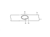
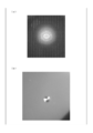
- FIG. 15 is a diagram showing the appearance of the surface of the glass substrate 1 before and after grinding in the above-described first to third embodiments.
- 15A shows the appearance of the surface of the glass substrate 1 before grinding
- FIG. 15B shows the appearance of the surface of the glass substrate 1 after grinding.
- a rotating member for rotating the injection direction changing member about the normal from the processing surface passing through the injection direction changing member may be further arranged. preferable.
- the substrate processing apparatus of the present invention can change the spraying direction of the abrasive grains after being reflected by the spraying direction changing member.
- the substrate processing apparatus of the present invention further includes an injection direction control member for changing an angle of the injection direction changing member with respect to a normal line from the processing surface passing through the injection direction changing member. It is preferable that
- the substrate processing apparatus of the present invention can control the spray angle of the abrasive after being reflected by the spray direction changing member.
- the jetting direction changing member contains at least one of silicon carbide and silicon nitride.
- the injection direction changing member is not easily deteriorated, and the efficiency of the substrate processing operation can be improved.
- the substrate is preferably a glass substrate, and the abrasive grains are preferably alumina.
- alumina has a hardness (Mohs) of 9, and can be suitably used as abrasive grains for grinding.
- the substrate processing apparatus of the present invention preferably alternately performs the ejection of abrasive grains and a medium for ejecting the abrasive grains and the ejection of only the medium.
- Abrasive grains that are sprayed and ground onto the processing part of the substrate remain in the grinding part. Therefore, the grinding efficiency of the next abrasive grain is obstructed, and the grinding efficiency decreases as the abrasive grain continues. To do.
- the ejection of abrasive grains and a medium for ejecting the abrasive grains and the ejection of only the medium are alternately performed.
- grinding of the processed portion of the substrate and removal of residues such as abrasive grains remaining in the ground portion are alternately performed, so that unnecessary abrasive grains can be eliminated.
- the substrate processing apparatus of the present invention can increase the grinding efficiency.
- the substrate processing apparatus of the present invention it is preferable to fill the processed portion of the substrate with a transparent material.
- the substrate processing apparatus of the present invention is filled with a transparent material (individual) in a portion (indentation, groove, etc.) from which the substrate has been removed by processing, and this portion is compared with an empty state.
- the refractive index change at this portion can be reduced.
- the substrate processing apparatus of the present invention can make the portion from which the substrate has been removed by the processing difficult to notice.
- the substrate processing apparatus of the present invention may be one in which the substrate constitutes a liquid crystal display panel.
- a substrate (glass substrate) for constituting a liquid crystal display panel has a low alkali metal content and a high melting point, and thus easily generates internal bubbles. Therefore, the substrate processing apparatus of the present invention is particularly effective for a substrate for constituting a liquid crystal display panel.
- the substrate processing method of the present invention is characterized in that in order to solve the above-described problems, the substrate processing apparatus is used for processing, and after the substrate is brittlely processed, the substrate is ductile processed.
- the substrate processing apparatus can perform ductile processing of the substrate after brittle processing of the substrate, so that the substrate surface after processing can be smoothed.
- the method for manufacturing a processed substrate of the present invention is characterized by including a step of using the substrate processing method in order to solve the above-mentioned problems.
- the surface of the manufactured processed substrate can be smoothed.
- the present invention can be used in all fields for processing brittle materials.
- a glass substrate constituting a flat display panel such as a liquid crystal display panel or a plasma display panel (PDP).
- PDP plasma display panel
Landscapes
- Engineering & Computer Science (AREA)
- Mechanical Engineering (AREA)
- Surface Treatment Of Glass (AREA)
- Liquid Crystal (AREA)
Abstract
Description
本発明の第1の実施形態について説明すれば、以下の通りである。なお、本発明はこれに限定されるものではなく、この実施の形態に記載されている構成部品の寸法、材質、形状、その相対配置などは、特に限定的な記載がない限り、この発明の範囲をそれのみに限定する趣旨ではなく、単なる説明例に過ぎない。なお、本明細書等において、範囲を示す「A~B」は、「A以上、B以下」であることを示す。
本発明の第2の実施形態について説明すれば以下の通りである。なお、説明の便宜上、前記実施の形態1にて説明した図面と同じ機能を有する部材については、同じ符号を付記し、その説明を省略する。
本発明の第3の実施形態について説明すれば以下の通りである。なお、説明の便宜上、前記実施の形態1にて説明した図面と同じ機能を有する部材については、同じ符号を付記し、その説明を省略する。
本発明の基板の加工装置は、上記噴射方向変更部材を通る、上記加工面からの法線を中心として上記噴射方向変更部材を回転させるための回転部材がさらに配置されているものであることが好ましい。
本発明は上述した各実施形態に限定されるものではなく、請求項に示した範囲で種々の変更が可能であり、異なる実施形態にそれぞれ開示された技術的手段を適宜組み合わせて得られる実施形態についても本発明の技術的範囲に含まれる。
1a 表面
1b 内部泡(修正対象欠陥、内部欠陥)
1c 内部異物(修正対象欠陥、内部欠陥)
1d ガラス材料
1d 取巻部
1e 修正面
1f 修正面
1p 突起(修正対象欠陥、内部欠陥)
1s 表面
1v 傷(修正対象欠陥、内部欠陥)
1w 加工面
2 透明材料
10 欠陥修正装置(加工装置)
11 筐体
11a 載置面
12 修正ヘッド(噴射部材)
12a 砥粒
13 基板載置台
14 ヘッド搭載台
15 反射板搭載台
16 回転部材
17 反射板支持部材
18 反射板(噴射方向変更部材)
19 噴射方向変更部材
20 液晶表示パネル
20a 表示領域
21 液晶
25 回転軸
27 反射板制御部材(噴射方向制御部材)
121 砥粒供給ノズル
121a 円筒先端孔
121b 円筒後端孔
121c 砥粒供給孔
122 加速ノズル
122a 噴射孔
122b エアー供給孔
122c 混合室
123 砥粒タンク
124 高速電磁弁
124a 接続用筒
124b エアー取込口
Claims (10)
- 基板の加工面に対する砥粒の噴射角度が脆性加工における角度となるように、該砥粒の噴射部材が配置された基板の加工装置であって、
上記砥粒の噴射方向における上記噴射部材と上記基板の加工面との間に、該基板の加工面への該砥粒の進入角度を上記脆性加工における角度から延性加工における角度に変更するための噴射方向変更部材が配置されているものであり、
上記噴射方向変更部材が移動可能であることを特徴とする基板の加工装置。 - 上記噴射方向変更部材を通る、上記加工面からの法線を中心として該噴射方向変更部材を回転させるための回転部材がさらに配置されているものであることを特徴とする請求項1に記載の基板の加工装置。
- 上記噴射方向変更部材を通る、上記加工面からの法線に対する該噴射方向変更部材の角度を変更するための噴射方向制御部材がさらに配置されているものであることを特徴とする請求項1または2に記載の基板の加工装置。
- 上記噴射方向変更部材が炭化ケイ素および窒化ケイ素のうちの少なくとも1つを含有するものであることを特徴とする請求項1~3のいずれか1項に記載の基板の加工装置。
- 上記基板がガラス基板であり、かつ上記砥粒がアルミナであることを特徴とする請求項1~4のいずれか1項に記載の基板の加工装置。
- 砥粒および該砥粒を噴射するための媒体の噴射と、該媒体のみの噴射とを、交互に行うことを特徴とする請求項1~5のいずれか1項に記載の基板の加工装置。
- 上記基板の加工部位に透明材料を充填することを特徴とする請求項1~6のいずれか1項に記載の基板の加工装置。
- 上記基板が液晶表示パネルを構成するためのものであることを特徴とする請求項1~7のいずれか1項に記載の基板の加工装置。
- 請求項1~8のいずれか1項に記載の基板の加工装置を用いて加工し、
基板の脆性加工の後に、基板の延性加工を行うことを特徴とする基板の加工方法。 - 請求項9に記載の基板の加工方法を用いる工程を含んでいることを特徴とする加工基板の製造方法。
Priority Applications (2)
| Application Number | Priority Date | Filing Date | Title |
|---|---|---|---|
| US13/383,855 US20120115399A1 (en) | 2009-07-15 | 2010-03-26 | Device and method for processing substrate, and method for producing a processed substrate |
| CN201080031670.XA CN102470509B (zh) | 2009-07-15 | 2010-03-26 | 基板的加工装置、基板的加工方法及加工基板的制造方法 |
Applications Claiming Priority (2)
| Application Number | Priority Date | Filing Date | Title |
|---|---|---|---|
| JP2009-167110 | 2009-07-15 | ||
| JP2009167110A JP2011020212A (ja) | 2009-07-15 | 2009-07-15 | 基板の加工装置および基板の加工方法、並びに加工基板の製造方法 |
Publications (1)
| Publication Number | Publication Date |
|---|---|
| WO2011007476A1 true WO2011007476A1 (ja) | 2011-01-20 |
Family
ID=43449088
Family Applications (1)
| Application Number | Title | Priority Date | Filing Date |
|---|---|---|---|
| PCT/JP2010/002197 Ceased WO2011007476A1 (ja) | 2009-07-15 | 2010-03-26 | 基板の加工装置および基板の加工方法、並びに加工基板の製造方法 |
Country Status (4)
| Country | Link |
|---|---|
| US (1) | US20120115399A1 (ja) |
| JP (1) | JP2011020212A (ja) |
| CN (1) | CN102470509B (ja) |
| WO (1) | WO2011007476A1 (ja) |
Families Citing this family (5)
| Publication number | Priority date | Publication date | Assignee | Title |
|---|---|---|---|---|
| CN103348397B (zh) * | 2011-02-18 | 2016-01-13 | 夏普株式会社 | 图像显示面板的修正方法 |
| KR20130090209A (ko) * | 2012-02-03 | 2013-08-13 | 삼성전자주식회사 | 기판처리장치 및 기판처리방법 |
| CN104209867A (zh) * | 2013-08-27 | 2014-12-17 | 东旭集团有限公司 | 玻璃基板表面处理的方法及系统 |
| WO2020168093A1 (en) * | 2019-02-13 | 2020-08-20 | Millerworks, Inc. D/B/A Pavo Real Glass | Method of etching glass |
| JP7517902B2 (ja) * | 2020-08-11 | 2024-07-17 | 日立Geニュークリア・エナジー株式会社 | 加工装置 |
Citations (1)
| Publication number | Priority date | Publication date | Assignee | Title |
|---|---|---|---|---|
| JP2009084120A (ja) * | 2007-10-01 | 2009-04-23 | Sharp Corp | ガラス基板の欠陥修正方法、ガラス基板の製造方法、表示パネル用ガラス基板、及び表示パネル |
Family Cites Families (9)
| Publication number | Priority date | Publication date | Assignee | Title |
|---|---|---|---|---|
| DE4039621A1 (de) * | 1990-12-12 | 1992-06-17 | Badische Maschf Gmbh | Strahlanlage zum strahlen der oberflaeche von blechen, profilen oder dergleichen |
| JPH0736982B2 (ja) * | 1991-11-18 | 1995-04-26 | 日本発条株式会社 | 板ばね目玉部のショットピーニング装置 |
| US5964644A (en) * | 1996-03-01 | 1999-10-12 | Extrude Hone Corporation | Abrasive jet stream polishing |
| JPH10239828A (ja) * | 1996-12-25 | 1998-09-11 | Konica Corp | フォトマスク用ガラスの欠陥修復方法 |
| NL1007589C1 (nl) * | 1997-11-20 | 1999-05-25 | Tno | Werkwijze en inrichting voor het bewerken van een werkstuk. |
| JP3546751B2 (ja) * | 1999-04-08 | 2004-07-28 | 株式会社日立製作所 | プラズマディスプレイ装置の製造方法およびプラズマディスプレイ装置 |
| TWI250133B (en) * | 2002-01-31 | 2006-03-01 | Shinetsu Chemical Co | Large-sized substrate and method of producing the same |
| JP4369307B2 (ja) * | 2004-06-09 | 2009-11-18 | 東京エレクトロン株式会社 | パターン加工方法及びパターン加工装置 |
| JP2008229765A (ja) * | 2007-03-19 | 2008-10-02 | Toyohashi Univ Of Technology | 硬脆材料のエアーブラスト加工方法およびその装置 |
-
2009
- 2009-07-15 JP JP2009167110A patent/JP2011020212A/ja active Pending
-
2010
- 2010-03-26 WO PCT/JP2010/002197 patent/WO2011007476A1/ja not_active Ceased
- 2010-03-26 US US13/383,855 patent/US20120115399A1/en not_active Abandoned
- 2010-03-26 CN CN201080031670.XA patent/CN102470509B/zh not_active Expired - Fee Related
Patent Citations (1)
| Publication number | Priority date | Publication date | Assignee | Title |
|---|---|---|---|---|
| JP2009084120A (ja) * | 2007-10-01 | 2009-04-23 | Sharp Corp | ガラス基板の欠陥修正方法、ガラス基板の製造方法、表示パネル用ガラス基板、及び表示パネル |
Also Published As
| Publication number | Publication date |
|---|---|
| CN102470509B (zh) | 2014-05-28 |
| CN102470509A (zh) | 2012-05-23 |
| JP2011020212A (ja) | 2011-02-03 |
| US20120115399A1 (en) | 2012-05-10 |
Similar Documents
| Publication | Publication Date | Title |
|---|---|---|
| JP5584884B2 (ja) | ガラス基板の欠陥修正方法、ガラス基板の製造方法 | |
| WO2011007476A1 (ja) | 基板の加工装置および基板の加工方法、並びに加工基板の製造方法 | |
| JP5267286B2 (ja) | ノズル、ノズルユニット及びブラスト加工装置 | |
| KR101939685B1 (ko) | 경질 취성 기판의 절취 방법 및 절취 장치 | |
| CN102413989A (zh) | 喷丸装置和喷丸加工方法 | |
| JP2013201424A (ja) | 半導体装置の製造方法 | |
| US8298045B2 (en) | Method of remedying glass substrate defect | |
| CN101060938B (zh) | 玻璃基板清洗装置及玻璃基板清洗方法 | |
| US20210394327A1 (en) | Systems and methods for forming multi-section displays | |
| JP2014100766A (ja) | サファイア基板 | |
| EP1566241B1 (en) | Method for preparing large-size substrate | |
| KR101454446B1 (ko) | 강화 유리의 절단 및 면취 방법 | |
| JP2003145426A (ja) | マスク用基板リサイクルのためのパターン除去方法およびそのパターン除去装置およびこれらでパターン除去されたマスク用基板 | |
| KR20060096973A (ko) | 워터제트를 이용한 표시창 제조용 원판유리의 절단방법 및절단장치 | |
| CN100333875C (zh) | 导光板的加工方法 | |
| CN116852267B (zh) | 一种超薄钽酸锂晶片背面粗糙化加工方法 | |
| CN207824714U (zh) | 一种用于视屏保玻璃的水切割机玻璃定位架 | |
| KR101555528B1 (ko) | 도포장치 및 그 잉크 충전방법 | |
| JP2005262432A (ja) | 大型基板の製造方法 | |
| KR101090546B1 (ko) | 에어 샌드 브라스트 유리절단용 머신의 전용지그 | |
| JP2004237415A (ja) | 材料加工方法及び加工装置 | |
| CN121200616A (zh) | 分色喷砂工艺 | |
| KR20060121624A (ko) | 액정패널의 절단장치 | |
| CN100355530C (zh) | 平面镜片研磨方法 | |
| KR20070045732A (ko) | 야그 레이저를 이용한 액정 패널의 초기 크랙 형성 장치 및 이를 이용한 액정 패널의 제조 방법 |
Legal Events
| Date | Code | Title | Description |
|---|---|---|---|
| WWE | Wipo information: entry into national phase |
Ref document number: 201080031670.X Country of ref document: CN |
|
| 121 | Ep: the epo has been informed by wipo that ep was designated in this application |
Ref document number: 10799540 Country of ref document: EP Kind code of ref document: A1 |
|
| WWE | Wipo information: entry into national phase |
Ref document number: 13383855 Country of ref document: US |
|
| NENP | Non-entry into the national phase |
Ref country code: DE |
|
| 122 | Ep: pct application non-entry in european phase |
Ref document number: 10799540 Country of ref document: EP Kind code of ref document: A1 |