WO2010146813A1 - 自動倉庫 - Google Patents
自動倉庫 Download PDFInfo
- Publication number
- WO2010146813A1 WO2010146813A1 PCT/JP2010/003893 JP2010003893W WO2010146813A1 WO 2010146813 A1 WO2010146813 A1 WO 2010146813A1 JP 2010003893 W JP2010003893 W JP 2010003893W WO 2010146813 A1 WO2010146813 A1 WO 2010146813A1
- Authority
- WO
- WIPO (PCT)
- Prior art keywords
- rail
- vertical
- horizontal
- automatic warehouse
- rail member
- Prior art date
- Legal status (The legal status is an assumption and is not a legal conclusion. Google has not performed a legal analysis and makes no representation as to the accuracy of the status listed.)
- Ceased
Links
Images


Classifications
-
- H—ELECTRICITY
- H10—SEMICONDUCTOR DEVICES; ELECTRIC SOLID-STATE DEVICES NOT OTHERWISE PROVIDED FOR
- H10P—GENERIC PROCESSES OR APPARATUS FOR THE MANUFACTURE OR TREATMENT OF DEVICES COVERED BY CLASS H10
- H10P72/00—Handling or holding of wafers, substrates or devices during manufacture or treatment thereof
- H10P72/30—Handling or holding of wafers, substrates or devices during manufacture or treatment thereof for conveying, e.g. between different workstations
- H10P72/34—Handling or holding of wafers, substrates or devices during manufacture or treatment thereof for conveying, e.g. between different workstations the wafers being stored in a carrier, involving loading and unloading
- H10P72/3404—Storage means
Definitions
- the present invention relates to an automatic warehouse, and more particularly to an automatic warehouse that stores articles between a transfer device and a processing device.
- semiconductor devices and liquid crystal devices are formed on a substrate through various processing configurations such as thin film formation, oxidation, and etching on a substrate such as a silicon wafer or a glass plate.
- the substrate is stored in a cassette (an example of an article) and conveyed by an automatic conveyance carriage in units of cassettes.
- a buffer called a pre-device automatic warehouse is provided at the delivery place between the processing device and the transfer device (see, for example, Patent Document 1).
- a conventional automatic warehouse in front of a device includes a plurality of cassette storage shelves and a transfer device capable of delivering articles between the shelves.
- the fixed shelves are arranged at intervals in the up and down and left and right directions, and the uppermost fixed shelf is a cassette delivery place with the automatic transport carriage as a transport device.
- the delivery port of the cassette with a processing apparatus is arrange
- the transfer device is arranged on the opposite side of the fixed shelf processing device, and transfers the cassette between the fixed shelves and between each fixed shelf and the delivery port.
- the transfer device includes a horizontal rail disposed over the entire length of the shelf in the left-right direction, a vertical rail that moves along the horizontal rail, and a transfer head that moves along the vertical rail.
- An object of the present invention is to improve the conveyance capacity while suppressing an increase in dead space.
- the automatic warehouse according to the present invention includes a rack having a plurality of shelves, a horizontal rail, a plurality of vertical rails, and a plurality of transfer heads.
- the plurality of shelves of the rack are for placing articles arranged in the vertical direction and the horizontal direction.
- the horizontal rail is a horizontal rail corresponding to the width of the rack, and has a plurality of rail bodies that are shorter than the width of the rack and are arranged at different positions in the vertical direction and the horizontal direction. At least one of the plurality of vertical rails is provided in each of the plurality of rail bodies, and moves along the plurality of rail bodies.
- the plurality of transfer heads are provided at least on each of the plurality of vertical rails, move along the plurality of vertical rails, respectively, and can transfer articles between the plurality of shelves.
- the vertical rail moves in the horizontal direction along each rail body
- the transfer head moves in the vertical direction along the vertical rail.
- the transfer head moves in the two-dimensional space in the automatic warehouse.
- multiple rail bodies of the horizontal rail are arranged at different vertical positions, and the horizontal rail itself corresponds to the width of the rack, so drive parts such as pulleys are arranged at both ends of the rail body
- a some vertical rail moves along a rail body, interference of a vertical rail does not arise. For this reason, the conveyance capability can be improved while suppressing an increase in dead space.
- An endless driving member that is disposed on each of the rail bodies and connected to the vertical rail to move the vertical rail in the horizontal direction, and a plurality of windings that are disposed at both ends of each rail body and on which the endless driving member is wound And a member.
- winding members for winding an endless driving member such as a chain and a toothed belt are arranged at both ends of each rail body, both end portions of the rail body protrude.
- the protruding portion does not interfere. For this reason, an increase in dead space can be minimized.
- the endless drive member may be a toothed belt, and the winding member may be a toothed pulley.
- the horizontal rail further has a connecting member that extends and connects only between the plurality of rail bodies.
- a connecting member that extends and connects only between the plurality of rail bodies.
- the horizontal rail connects the first rail body, the second rail body that is disposed at a position higher than the first rail body and is symmetrical with the first rail body, and the first rail body and the second rail body. And a connecting member.
- the first rail body includes a first upper rail member, and a first lower rail member disposed immediately below the first upper rail member
- the second rail body includes a second upper rail member disposed at a height corresponding to the upper side of the first upper rail member, and a first upper rail member and a first lower rail member that are directly below the second upper rail member. And a second lower rail member disposed at a height corresponding to between the upper and lower directions.
- the connection member has an upper connection member that connects the first upper rail member and the second upper rail member, a lower connection member that connects the first lower rail member, and the second lower rail member. May be.
- the connecting member may connect the first upper rail member, the second upper rail member, the first lower rail member, and the second lower rail member, and may connect the first upper rail member and the second lower rail member.
- the horizontal rail has a plurality of rail bodies arranged at different heights, even if driving parts such as pulleys are arranged at both ends of the rail body, an increase in dead space occurs due to them. Absent. Moreover, since a some vertical rail moves along a rail body, interference of a vertical rail does not arise. For this reason, the conveyance capability can be improved while suppressing an increase in dead space.
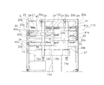
- FIG. 1 The front view of the automatic warehouse by one Embodiment of this invention.
- FIG. 1 The enlarged front view of a 1st rail body.
- an automatic warehouse 10 according to an embodiment of the present invention is, for example, between an unillustrated overhead traveling automatic carriage and a semiconductor processing apparatus 12 (FIG. 2). It is an automatic warehouse in front of the equipment.
- the automatic warehouse 10 is disposed so as to overlap the delivery port 14 disposed on the outer periphery of the semiconductor processing apparatus 12.
- the delivery port 14 has, for example, four cassette mounting tables 14a.
- the automatic warehouse 10 stores a cassette (an example of an article) C that stores a plurality of substrates before processing, which are loaded from an automatic conveyance cart and processed by the semiconductor processing apparatus 12.
- the cassette C storing the processed substrates processed by the semiconductor processing apparatus 12 and carried out by the automatic transfer cart is stored.
- the automatic warehouse 10 includes a frame 20, a rack 25 including an outer wall panel 22 that covers the outer surface of the frame 20, a shelf 24 for storing cassette C, and a transfer device 26.
- the transfer device 26 conveys the cassette C between the shelf 24 and the shelf 24 and between the shelf 24 and the cassette mounting table 14a.
- the frame 20 includes, for example, four column members 20a arranged at four corners, and a connecting member 20b that connects the column members 20a in the front-rear and left-right directions.
- the connecting member 20b that connects the left and right is mainly disposed on the back surface on the semiconductor processing apparatus 12 side, and is not disposed on the front surface.
- the two column members 20a on the left and right sides of the frame 20 can be fixed to the floor.
- a delivery port 14 of the semiconductor processing apparatus 12 is disposed below the frame 20. The delivery port 14 can be loaded with the cassette C. In the semiconductor processing apparatus 12, the cassette C is opened and processed, for example, a circular substrate stored inside, and the processed substrate is stored in the cassette C.
- the outer wall panel 22 is formed so as to cover the front and left and right side surfaces of the automatic warehouse 10 and the upper part of the back.
- the shelf 24 of the rack 25 is arranged in the vertical direction and the horizontal direction. In this embodiment, a total of 12 columns are provided in four rows on the left and right and three rows on the top and bottom.
- the shelf 24 can be placed by positioning the cassette C on the upper surface.
- the shelf 24 is fixed to the left and right connecting members 20 b of the frame 20.
- a vertical passage 30 a through which the transfer device 26 can pass up and down is provided between the shelves 24.
- the shelves 24 are arranged in the order of the shelf 24, the vertical passage 30a, the shelf 24, the shelf 24, the vertical passage 30a, and the shelf 24 in the left-right direction, and all the shelves 24 face the vertical passage 30a. ing.
- the transfer device 26 can transfer the cassette C between all the shelves 24 and the delivery port 14.
- the shelf 24 is provided with a cassette reader (not shown) for identifying the cassette C.
- the uppermost shelf 24 is used for delivery of the cassette C to and from the automatic conveyance carriage.
- a horizontal passage 30b is provided between the lowermost shelf 24 and the delivery port 14.
- the transfer device 26 is a device having two axes, a horizontal axis and a vertical axis along the left-right direction, and can hold the cassette C by moving in the horizontal axis direction.
- the transfer device 26 moves separately along the horizontal rail 32, the first vertical rail 34 and the second vertical rail 35 that move along the horizontal rail 32, and the first vertical rail 34 and the second vertical rail 35.
- a first transfer head 36 and a second transfer head 37 are provided.
- the horizontal rail 32 is arranged in the horizontal direction with a gap from the shelf 24 on the front side of the shelf 24.
- the horizontal rail 32 is arrange
- the horizontal rail 32 includes a first rail body 40 and a second rail body 41 that are shorter than the total length in the left-right direction of the plurality of shelves 24 and are arranged at different heights in the vertical direction, and the first rail body 40 and the second rail. And a connection member 42 for connecting the body 41.
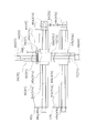
- FIG. 3 is a front view of the first rail body 40 and is a view of the first rail body 40 as viewed from the back side of the automatic warehouse 10.
- the first rail body 40 includes a first upper rail member 40a and a first lower rail member 40b disposed below the first upper rail member 40a.
- the first rail body 40 includes a first horizontal drive motor 44 for driving the first vertical rail 34 in the horizontal direction, a first upper drive pulley (an example of a winding member) 46a, and a first lower drive pulley ( An example of a winding member 46b, a first upper driven pulley (an example of a winding member) 48a and a first lower driven pulley (an example of a winding member) 48b, a first upper toothed belt 50a and a first lower tooth Attached belt (an example of an endless drive member) 50b.
- the first horizontal drive motor 44 is a motor with a speed reducer fixed to the right end of FIG. 3 (left end of FIG. 2) of the first upper rail member 40a, and can be rotated by bending 90 degrees.
- the output of the first horizontal drive motor 44 is transmitted to the first upper drive pulley 46 a and is transmitted to the first lower drive pulley 46 b via the first connecting shaft 54.
- the first upper drive pulley 46a and the first lower drive pulley 46b are arranged at positions that overlap in a plan view of the right end of FIG. 3 (the left end of FIG. 1) of the first upper rail member 40a and the first lower rail member 40b.
- the first upper driven pulley 48a and the first lower driven pulley 48b are arranged at positions that overlap in plan view at the left end in FIG. 3 (the right end in FIG. 1) of the first upper rail member 40a and the first lower rail member 40b.
- the first upper toothed belt 50a is wound around a first upper drive pulley 46a and a first upper driven pulley 48a.
- a first upper slider 52a guided in the horizontal direction by the first upper rail member 40a is fixed to the first upper toothed belt 50a.
- a first lower slider 52b guided in the horizontal direction by the first lower rail member 40b is fixed to the first lower toothed belt 50b.
- the first vertical rail 34 is fixed to the first upper slider 52a and the first lower slider 52b.
- the second rail body 41 is arranged at a position higher than the first rail body 40 and has a line-symmetric structure with the first rail body 40 in plan view. Accordingly, the second horizontal drive motor 45 is disposed on the right side of FIG.
- the second rail body 41 includes a second upper rail member 41a, a second lower rail member 41b, a second horizontal drive motor 45, a second upper drive pulley 47a and a second upper driven pulley 49a, and a second lower drive.
- the output of the second horizontal drive motor 45 is transmitted to the second upper drive pulley 47 a via the second upper drive pulley 47 a and the second connecting shaft 55.
- the second upper drive pulley 47a and the second lower drive pulley 47b are arranged at positions where the second upper rail member 41a and the second lower rail member 41b overlap in a plan view of the right end of FIG.
- the second upper driven pulley 49a and the second lower driven pulley 49b are arranged at positions where the second upper rail member 41a and the second lower rail member 41b overlap in a plan view of the left end in FIG.
- the connection member 42 includes an upper connection member 42a that connects the first upper rail member 40a and the second upper rail member 41a, and a lower connection member 42b that connects the first lower rail member 40b and the second lower rail member 41b.
- the upper connection member 42a and the lower connection member 42b are plate-like members, and are, for example, bolts, the first upper rail member 40a and the second upper rail member 41a, and the first lower rail member 40b and the second lower rail member 41b.
- the first upper rail member 40a, the second upper rail member 41a, the first lower rail member 40b, and the second lower rail member 41b can be positioned by a step or the like.
- the first vertical rail 34 includes a first vertical rail member 60, a first vertical drive motor 64 for driving the first transfer head 36 in the vertical direction, and a first drive pulley 66.
- the first driven pulley 68 and the first toothed belt 70 are provided. These structures are the same as the first rail body 40 of the horizontal rail 32.
- the first transfer head 36 is fixed to a first slider 72 fixed to a first toothed belt 70.
- the second vertical rail 35 includes a second vertical rail member 61, a second vertical drive motor 65 for driving the second transfer head 37 in the vertical direction, a second drive pulley 67, and a second driven pulley. 69 and a second toothed belt 71.
- the second transfer head 37 is fixed to a second slider 73 fixed to the second toothed belt 71.
- the first transfer head 36 and the second transfer head 37 include a pair of first holding portions 36 a and a first holding portion 36 a that can hold a protruding portion C ⁇ b> 1 that protrudes from the upper surface of the cassette C.
- the two holding portions 37a are arranged separately so as to be openable and closable in the left-right direction (the direction orthogonal to the plane of FIG. 2).
- a first cassette identification sensor 36b and a second cassette identification sensor 37b for identifying the cassette C are separately provided at positions where the first transfer head 36 and the second transfer head 37 can face the cassette C. It has been.
- the first transfer head 36 and the second transfer head 37 each have a head motor (not shown) that opens and closes the first holding part 36a and the second holding part 37a.
- the first transfer head 36 and the second transfer head 37 open and close the first holding portion 36a and the second holding portion 37a when releasing and holding the protrusion C1 when carrying in and out of the shelf 24.
- the first transfer head 36 is guided by the first rail body 40 and the first vertical rail 34 to move in the left vertical passage 30a and the left half horizontal passage 30b
- the second transfer head. 37 is guided by the second rail body 41 and the second vertical rail 35 and moves in the right vertical passage 30a and the right half horizontal passage 30b.
- the first rail body 40, the first vertical rail 34, and the first transfer head 36 are in charge of the transfer of the cassette C in the left half of FIG. To do. Further, the second rail body 41, the second vertical rail 35, and the second transfer head 37 are in charge of transferring the half cassette C on the right side of FIG. Then, an automatic conveyance cart (not shown) carries the cassette C into one of the uppermost shelves 24. The loaded cassette C is transferred from the vertical passage 30a facing the loaded uppermost shelf 24 to one of the two lower rows of the shelves 24. Then, it is further transferred to the delivery port 14 in response to a request from the semiconductor processing apparatus 12.
- the first transfer head 36 (or the second transfer head 37) is placed above the center of the cassette C to be transferred with the first holding part 36a (or the second holding part 37a) opened. Move to. At this time, it is moved to the vertical passage 30a facing the cassette C to be transferred and moved up and down along the first vertical rail 34 (or the second vertical rail 35). Then, when reaching the upper side of the cassette C, it is moved horizontally above the center of the cassette C along the first rail body 40 (or the second rail body 41). Then, the first transfer head 36 (or the second transfer head 37) is lowered, the first holding portion 36a (or the second holding portion 37a) is closed by the head motor, and the protrusion C1 is connected to the first holding portion 36a.
- the automatic warehouse 10 includes a rack 25 including a plurality of shelves 24, a horizontal rail 32, a first vertical rail 34 and a second vertical rail 35, a first transfer head 36, and a second transfer. Loading head 37.
- the plurality of shelves 24 of the rack 25 are for placing articles arranged in the vertical direction and the horizontal direction.
- the horizontal rail 32 is a horizontal rail corresponding to the width of the rack 25, is shorter than the width of the rack 25, and is arranged with the first rail body 40 and the first rail body 40 arranged at different positions in the vertical direction and the horizontal direction.
- a two-rail body 41 is provided.
- the first vertical rail 34 is provided on the first rail body 40, and the second vertical rail 35 is provided on the second rail body 41, and moves along the first rail body 40 and the second rail body 41.
- the first transfer head 36 is provided on the first vertical rail 34, and the second transfer head 37 is provided on the second vertical rail 35.
- the first transfer head 36 is provided along the first vertical rail 34 and the second vertical rail 35, respectively.
- the cassette C can be moved between the plurality of shelves 24.
- the first vertical rail 34 and the second vertical rail 35 move in the horizontal direction along the first rail body 40 and the second rail body 41, and the first vertical rail 34 and the second vertical rail 35 are moved to the horizontal direction.
- the 1st transfer head 36 and the 2nd transfer head 37 move to an up-down direction along.
- the 1st transfer head 36 and the 2nd transfer head 37 move in the two-dimensional space in an automatic warehouse.
- the first rail body 40 and the second rail body 41 of the horizontal rail 32 are arranged at different vertical positions, and the horizontal rail 32 itself corresponds to the width of the rack 25.
- drive parts such as pulleys are arranged at both ends of the body 40 and the second rail body 41, an increase in dead space due to them is not caused.
- the 1st vertical rail 34 and the 2nd vertical rail 35 move along the 1st rail body 40 and the 2nd rail body 41, the interference of the 1st vertical rail 34 and the 2nd vertical rail 35 does not arise. For this reason, the conveyance capability can be improved while suppressing an increase in dead space.
- the transfer device 26 is disposed on the first rail body 40 and the second rail body 41, respectively, and is connected to the first vertical rail 34 and the second vertical rail 35 to be connected to the first vertical rail 34 and the second vertical rail.
- An endless drive member of the first upper toothed belt 50a that moves the belt 35 in the horizontal direction, a first upper drive pulley 46a around which the first upper toothed belt 50a is wound, and a winding member of the first lower toothed belt 50b It has further. For this reason, when winding members for winding an endless drive member such as a chain and a toothed belt are disposed at both ends of the first rail body 40 and the second rail body 41, the first rail body 40 and the second rail body 41 Both ends protrude. However, since the heights of the first rail body 40 and the second rail body 41 are different, the protruding portion does not interfere. For this reason, an increase in dead space can be minimized.
- the horizontal rail 32 further includes a connecting member 42 that extends and connects only between the first rail body 40 and the second rail body 41. For this reason, since the 1st rail body 40 and the 2nd rail body 41 from which a vertical direction position differs are connected by the connection member 42 extended only between rail bodies, the space up and down of the connection member 42 can be utilized. And increase in dead space can be suppressed.
- the present invention is not limited to an automatic warehouse in front of an apparatus for transferring to a semiconductor processing apparatus, and can be applied to all automatic warehouses for transferring articles by a horizontal rail and a vertical rail.
- connection member 42 that connects only the first rail body 40 and the second rail body 41 is not limited to the above embodiment.
- the connecting member 142 of the horizontal rail 132 of the automatic warehouse 110 connects the first upper rail member 40a and the second upper rail member 41a, and the first lower rail member 40b and the second lower rail member 41b.
- the first lower rail member 40b and the second upper rail member 41a are connected.
- the rigidity of the entire horizontal rail 132 is increased.
- the horizontal rail 32 is divided into two, but it may be divided into three or more. In this case, as many vertical rails as the number of divisions are required. However, since the dead space increases as the number of divisions increases, the number of divisions can be appropriately set according to the length of the entire shelf in the left-right direction.
- the present invention has a horizontal rail and a vertical rail, and can be widely applied to automatic warehouses for storing articles.
Landscapes
- Warehouses Or Storage Devices (AREA)
Abstract
自動倉庫10を説明する。ラック25の複数の棚24は、上下方向及び水平方向に配置された物品載置用のものである。水平レール32は、ラック25の幅に対応している水平レールであって、ラック25の幅よりも短く、さらに上下方向および水平方向に位置を異ならせて配置される第1レール体40及び第2レール体41を有する。第1鉛直レール34は第1レール体40に、第2鉛直レール35は第2レール体41に、それぞれ設けられ、第1レール体40及び第2レール体41に沿って移動する。第1移載ヘッド36は、第1鉛直レール34に、第2移載ヘッド37は、第2鉛直レール35に、それぞれに設けられ、第1鉛直レール34及び第2鉛直レール35に沿ってそれぞれ移動し、カセットCを複数の棚24の間で移載可能である。
Description
本発明は、自動倉庫、特に、搬送装置と処理装置との間で物品を保管する自動倉庫に関する。
半導体や液晶の製造工場では、シリコンウェハやガラスプレート等の基板上に薄膜形成、酸化、エッチング等の種々の処理構成を経て基板上に半導体デバイスや液晶デバイスが形成される。この種の処理装置の間では、カセット(物品の一例)に基板が収納されてカセット単位で自動搬送台車により搬送される。処理装置と搬送装置との受け渡し場所には、搬送装置と処理装置との間の処理時間を調整するために装置前自動倉庫と呼ばれるバッファが設けられている(たとえば、特許文献1参照)。
従来の装置前自動倉庫は、カセット保管用の複数の棚と、各棚の間で物品を受け渡し可能な移載装置と、を備えている。固定棚は上下及び左右に間隔を隔てて配置されており、最も上の固定棚が搬送装置である自動搬送台車とのカセット受け渡し場所になっている。そして、最も下の固定棚の下方に処理装置とのカセットの受け渡しポートが配置されている。この受け渡しポートで処理装置によりカセット内から基板が取り出され、処理装置で基板が処理される。
移載装置は、固定棚の処理装置と逆側に面して配置され、各固定棚間及び各固定棚と受け渡しポートとの間でカセットを移載する。移載装置は、左右方向の棚の全長にわたり配置された水平レールと、水平レールに沿って移動する鉛直レールと、鉛直レールに沿って移動する移載ヘッドと、を備えている。
このような装置前自動倉庫を設けることにより、処理装置や搬送装置のトラブルによりカセットの供給又は搬出が滞っても、システムダウンすることなく連続して物品を搬入及び搬出することができる。
このような自動倉庫において、移載ヘッドが1台しかないと、取り扱う物品の量が増加すると搬送能力が不足することがある。そこで、水平レールに複数の鉛直レールと移載ヘッドとを配置することが考えられる。しかし、鉛直レール及び移載ヘッドを水平レールに複数配置すると、鉛直レール同士の干渉により搬送能力が向上しないおそれがある。
そこで、1本の水平レールでの鉛直レールの移動領域を制限することが考えられる。しかし、移動領域を制限すると、水平レールにデッドスペースが増加して自動倉庫が大型化するおそれがある。
本発明の課題は、デッドスペースの増加を抑えて搬送能力を向上させることにある。
本発明に係る自動倉庫は、複数の棚を有するラックと、水平レールと、複数の鉛直レールと、複数の移載ヘッドと、を備えている。ラックの複数の棚は、上下方向及び水平方向に配置された物品載置用のものである。水平レールは、ラックの幅に対応している水平レールであって、ラックの幅よりも短くさらに上下方向および水平方向に位置を異ならせて配置される複数のレール体を有する。複数の鉛直レールは、複数のレール体のそれぞれに少なくとも1つ設けられ、複数のレール体に沿って移動する。複数の移載ヘッドは、複数の鉛直レールのそれぞれに少なくとも1つ設けられ、複数の鉛直レールに沿ってそれぞれ移動し、物品を複数の棚の間で移載可能である。
この自動倉庫では、各レール体に沿って鉛直レールが水平方向に移動し、鉛直レールに沿って移載ヘッドが上下方向に移動する。これにより、自動倉庫内の二次元空間を移載ヘッドが移動する。
ここでは、水平レールの複数のレール体が上下方向位置を異ならせて配置されており、水平レール自体はラックの幅に対応しているので、レール体の両端部にプーリ等の駆動部品を配置してもそれらによるデッドスペースの増加が生じない。また、複数の鉛直レールがレール体に沿って移動するので、鉛直レールの干渉が生じない。このため、デッドスペースの増加を抑えて搬送能力を向上させることができる。
この自動倉庫では、各レール体に沿って鉛直レールが水平方向に移動し、鉛直レールに沿って移載ヘッドが上下方向に移動する。これにより、自動倉庫内の二次元空間を移載ヘッドが移動する。
ここでは、水平レールの複数のレール体が上下方向位置を異ならせて配置されており、水平レール自体はラックの幅に対応しているので、レール体の両端部にプーリ等の駆動部品を配置してもそれらによるデッドスペースの増加が生じない。また、複数の鉛直レールがレール体に沿って移動するので、鉛直レールの干渉が生じない。このため、デッドスペースの増加を抑えて搬送能力を向上させることができる。
複数のレール体にそれぞれ配置され、鉛直レールに連結されて鉛直レールを水平方向に移動させる無端駆動部材と、各レール体の両端部に配置され、無端駆動部材が巻回された複数の巻回部材と、をさらに備えてもよい。
この場合には、チェーン、歯付きベルト等の無端駆動部材を巻回する巻回部材を各レール体の両端に配置すると、レール体の両端部が突出する。しかし、2つのレール体の高さが異なっているので、突出部分が干渉しない。このため、デッドスペースの増加を最小限に抑えることができる。
この場合には、チェーン、歯付きベルト等の無端駆動部材を巻回する巻回部材を各レール体の両端に配置すると、レール体の両端部が突出する。しかし、2つのレール体の高さが異なっているので、突出部分が干渉しない。このため、デッドスペースの増加を最小限に抑えることができる。
無端駆動部材は、歯付きベルトであり、巻回部材は歯付きプーリでもよい。
水平レールは、複数のレール体の間のみ延びて接続する接続部材をさらに有する。この場合に、高さが異なる複数のレール体がレール体の間のみ延びる接続部材で接続されているので、接続部材の上下のスペースを利用することができ、デッドスペースの増加を抑えることができる。
水平レールは、第1レール体と、第1レール体より高い位置に配置され第1レール体と平面視線対称の構造の第2レール体と、第1レール体と第2レール体とを連結する接続部材と、を有してもよい。
第1レール体は、第1上レール部材と、第1上レール部材の真下に配置された第1下レール部材と、を有し、
第2レール体は、第1上レール部材の上方に対応する高さに配置された第2上レール部材と、第2上レール部材の真下であって第1上レール部材と第1下レール部材の上下方向間に対応する高さに配置された第2下レール部材と、を有してもよい。
接続部材は、第1上レール部材と、第2上レール部材と、を連結する上接続部材と、第1下レール部材と、第2下レール部材と、を連結する下接続部材と、を有してもよい。
第2レール体は、第1上レール部材の上方に対応する高さに配置された第2上レール部材と、第2上レール部材の真下であって第1上レール部材と第1下レール部材の上下方向間に対応する高さに配置された第2下レール部材と、を有してもよい。
接続部材は、第1上レール部材と、第2上レール部材と、を連結する上接続部材と、第1下レール部材と、第2下レール部材と、を連結する下接続部材と、を有してもよい。
接続部材は、第1上レール部材と第2上レール部材及び第1下レール部材と第2下レール部材を接続するとともに、第1上レール部材と第2下レール部材を接続してもよい。
本発明によれば、水平レールが高さを異ならせて配置された複数のレール体を有するので、レール体の両端部にプーリ等の駆動部品を配置してもそれらによるデッドスペースの増加が生じない。また、複数の鉛直レールがレール体に沿って移動するので、鉛直レールの干渉が生じない。このため、デッドスペースの増加を抑えて搬送能力を向上させることができる。
(1)自動倉庫の全体構成
図1及び図2において、本発明の一実施形態による自動倉庫10は、たとえば、図示しない天井走行の自動搬送台車と半導体処理装置12(図2)との間に配置される装置前自動倉庫である。自動倉庫10は、半導体処理装置12の外周に配置された受け渡しポート14に重なるように配置されている。受け渡しポート14は、たとえば、4個のカセット載置台14aを有している。
図1及び図2において、本発明の一実施形態による自動倉庫10は、たとえば、図示しない天井走行の自動搬送台車と半導体処理装置12(図2)との間に配置される装置前自動倉庫である。自動倉庫10は、半導体処理装置12の外周に配置された受け渡しポート14に重なるように配置されている。受け渡しポート14は、たとえば、4個のカセット載置台14aを有している。
自動倉庫10は、自動搬送台車から搬入され半導体処理装置12で処理される処理前の複数枚の基板を収納するカセット(物品の一例)Cを保管する。また、半導体処理装置12で処理され自動搬送台車で搬出される処理済みの基板が収納されたカセットCを保管する。自動倉庫10は、フレーム20と、フレーム20の外側面を覆う外壁パネル22と、カセットC保管用の棚24とを含むラック25と、移載装置26と、を備えている。移載装置26は、カセットCを棚24と棚24との間及び棚24とカセット載置台14aとの間で搬送する。
(2)フレーム及び外壁パネルの構成
フレーム20は、たとえば、四隅に配置された4本の柱部材20aと、柱部材20aを前後左右に連結する連結部材20bと、を有している。なお、左右をつなぐ連結部材20bは、主に半導体処理装置12側の背面に配置されており、正面には配置されていない。フレーム20の左右のそれぞれ2本の柱部材20aは、床に固定可能である。フレーム20の下部に半導体処理装置12の受け渡しポート14が配置されている。受け渡しポート14は、カセットCを載置可能である。半導体処理装置12では、カセットCを開けて内部に収納された、たとえば円形の基板に処理を施し、処理済みの基板をカセットCに収納する。
フレーム20は、たとえば、四隅に配置された4本の柱部材20aと、柱部材20aを前後左右に連結する連結部材20bと、を有している。なお、左右をつなぐ連結部材20bは、主に半導体処理装置12側の背面に配置されており、正面には配置されていない。フレーム20の左右のそれぞれ2本の柱部材20aは、床に固定可能である。フレーム20の下部に半導体処理装置12の受け渡しポート14が配置されている。受け渡しポート14は、カセットCを載置可能である。半導体処理装置12では、カセットCを開けて内部に収納された、たとえば円形の基板に処理を施し、処理済みの基板をカセットCに収納する。
外壁パネル22は、自動倉庫10の正面及び左右の側面を覆うとともに、背面の上部を覆うように形成されている。
(3)棚の構成
ラック25の棚24は、上下方向及び左右方向に配置されている。この実施形態では、左右に4列、上下に3段の合計12個設けられている。棚24は、上面にカセットCを位置決めして載置可能である。棚24は、フレーム20の左右の連結部材20bに固定されている。左右方向において、棚24の間に移載装置26が上下に通過可能な鉛直通路30aが設けられている。この実施形形態では、棚24は、左右方向において、棚24,鉛直通路30a,棚24,棚24、鉛直通路30a,棚24の順に並んでおり、すべての棚24が鉛直通路30aに面している。これにより、移載装置26がすべての棚24及び受け渡しポート14との間でカセットCを移載できる。棚24には、カセットCを識別するカセット読み取り器(図示せず)が設けられている。最上段の棚24は、自動搬送台車とのカセットCの受け渡しに使用される。最下段の棚24と受け渡しポート14との間は、水平通路30bとなっている。
ラック25の棚24は、上下方向及び左右方向に配置されている。この実施形態では、左右に4列、上下に3段の合計12個設けられている。棚24は、上面にカセットCを位置決めして載置可能である。棚24は、フレーム20の左右の連結部材20bに固定されている。左右方向において、棚24の間に移載装置26が上下に通過可能な鉛直通路30aが設けられている。この実施形形態では、棚24は、左右方向において、棚24,鉛直通路30a,棚24,棚24、鉛直通路30a,棚24の順に並んでおり、すべての棚24が鉛直通路30aに面している。これにより、移載装置26がすべての棚24及び受け渡しポート14との間でカセットCを移載できる。棚24には、カセットCを識別するカセット読み取り器(図示せず)が設けられている。最上段の棚24は、自動搬送台車とのカセットCの受け渡しに使用される。最下段の棚24と受け渡しポート14との間は、水平通路30bとなっている。
(4)移載装置の構成
移載装置26は、左右方向に沿った水平軸及び鉛直軸の二軸を有する装置であり、カセットCを水平軸方向の移動で保持可能である。移載装置26は、水平レール32と、水平レール32に沿って移動する第1鉛直レール34及び第2鉛直レール35と、第1鉛直レール34及び第2鉛直レール35に沿って各別に移動する第1移載ヘッド36及び第2移載ヘッド37と、を備えている。水平レール32は、棚24の正面側に棚24と隙間を空けて水平方向に配置されている。
移載装置26は、左右方向に沿った水平軸及び鉛直軸の二軸を有する装置であり、カセットCを水平軸方向の移動で保持可能である。移載装置26は、水平レール32と、水平レール32に沿って移動する第1鉛直レール34及び第2鉛直レール35と、第1鉛直レール34及び第2鉛直レール35に沿って各別に移動する第1移載ヘッド36及び第2移載ヘッド37と、を備えている。水平レール32は、棚24の正面側に棚24と隙間を空けて水平方向に配置されている。
図2及び図3に示すように、水平レール32は、左右方向に沿って配置されている。水平レール32は、複数の棚24の左右方向の全長より短く上下方向に高さを異ならせて配置された第1レール体40及び第2レール体41と、第1レール体40と第2レール体41とを接続する接続部材42と、を有している。なお、図3は、第1レール体40の正面図であり、第1レール体40を自動倉庫10の背面側から見た図である。
第1レール体40は、図3に示すように、第1上レール部材40aと、第1上レール部材40aの下方に配置された第1下レール部材40bと、を有している。また、第1レール体40は、第1鉛直レール34を水平方向に駆動するための第1水平駆動モータ44と、第1上駆動プーリ(巻回部材の一例)46a及び第1下駆動プーリ(巻回部材の一例)46bと、第1上従動プーリ(巻回部材の一例)48a及び第1下従動プーリ(巻回部材の一例)48bと、第1上歯付きベルト50a及び第1下歯付きベルト(無端駆動部材の一例)50bと、を有している。
第1レール体40は、図3に示すように、第1上レール部材40aと、第1上レール部材40aの下方に配置された第1下レール部材40bと、を有している。また、第1レール体40は、第1鉛直レール34を水平方向に駆動するための第1水平駆動モータ44と、第1上駆動プーリ(巻回部材の一例)46a及び第1下駆動プーリ(巻回部材の一例)46bと、第1上従動プーリ(巻回部材の一例)48a及び第1下従動プーリ(巻回部材の一例)48bと、第1上歯付きベルト50a及び第1下歯付きベルト(無端駆動部材の一例)50bと、を有している。
第1水平駆動モータ44は、第1上レール部材40aの図3右端(図2左端)に固定された減速機付きのモータであり、90度折り曲げて回転を出力可能である。第1水平駆動モータ44の出力は、第1上駆動プーリ46aに伝達され、かつ第1連結軸54を介して第1下駆動プーリ46bに伝達される。第1上駆動プーリ46a及び第1下駆動プーリ46bは、第1上レール部材40a及び第1下レール部材40bの図3右端(図1の左端)の平面視で重なる位置に配置されている。第1上従動プーリ48a及び第1下従動プーリ48bは、第1上レール部材40a及び第1下レール部材40bの図3左端(図1の右端)の平面視で重なる位置に配置されている。第1上歯付きベルト50aは、第1上駆動プーリ46aと第1上従動プーリ48aに巻回されている。第1上歯付きベルト50aには、第1上レール部材40aに水平方向に案内される第1上スライダ52aが固定されている。第1下歯付きベルト50bには、第1下レール部材40bに水平方向に案内される第1下スライダ52bが固定されている。第1上スライダ52a及び第1下スライダ52bに第1鉛直レール34が固定されている。
第2レール体41は、第1レール体40より高い位置に配置され、かつ第1レール体40と平面視で線対称の構造である。したがって、第2水平駆動モータ45は、図2右側に配置されている。第2レール体41は、第2上レール部材41aと、第2下レール部材41bと、第2水平駆動モータ45と、第2上駆動プーリ47a及び第2上従動プーリ49aと、第2下駆動プーリ47b及び第2下従動プーリ49bと、第2上歯付きベルト51a及び第2下歯付きベルト51bと、第2鉛直レール35が固定される第2上スライダ53a及び第2下スライダ53bと、を有している。第2水平駆動モータ45の出力は、第2上駆動プーリ47aと、第2連結軸55を介して第2下駆動プーリ47bとに伝達される。第2上駆動プーリ47a及び第2下駆動プーリ47bは、第2上レール部材41a及び第2下レール部材41bの図1の右端の平面視で重なる位置に配置されている。第2上従動プーリ49a及び第2下従動プーリ49bは、第2上レール部材41a及び第2下レール部材41bの図1の左端の平面視で重なる位置に配置されている。なお、これらの符号は、参考のために図3の括弧内に付している。
接続部材42は、第1上レール部材40aと第2上レール部材41aを接続する上接続部材42aと、第1下レール部材40bと第2下レール部材41bを接続する下接続部材42bと、を有している。上接続部材42a及び下接続部材42bは、板状の部材であり、たとえば、ボルトにより、第1上レール部材40a及び第2上レール部材41a並びに第1下レール部材40b及び第2下レール部材41bを固定する。また、段差等により、第1上レール部材40a及び第2上レール部材41a並びに第1下レール部材40b及び第2下レール部材41bを位置決め可能である。
第1鉛直レール34は、図3に示すように、第1鉛直レール部材60と、第1移載ヘッド36を鉛直方向に駆動するための第1鉛直駆動モータ64と、第1駆動プーリ66と、第1従動プーリ68と、第1歯付きベルト70と、を有している。これらの構造は、水平レール32の第1レール体40と同様である。第1移載ヘッド36は、第1歯付きベルト70に固定された第1スライダ72に固定されている。同様に第2鉛直レール35は、第2鉛直レール部材61と、第2移載ヘッド37を鉛直方向に駆動するための第2鉛直駆動モータ65と、第2駆動プーリ67と、第2従動プーリ69と、第2歯付きベルト71と、を有している。第2移載ヘッド37は、第2歯付きベルト71に固定された第2スライダ73に固定されている。
第1移載ヘッド36及び第2移載ヘッド37には、図2に示すように、カセットCの上面に突出して形成された突起部C1を保持可能な1対の第1保持部36a及び第2保持部37aが左右方向(図2紙面直交方向)に開閉可能に各別に配置されている。また、第1移載ヘッド36及び第2移載ヘッド37のカセットCに対向可能な位置には、カセットCを識別するための第1カセット識別センサ36b及び第2カセット識別センサ37bが各別に設けられている。第1移載ヘッド36及び第2移載ヘッド37は、第1保持部36a及び第2保持部37aを開閉する図示しないヘッドモータを各別に有している。第1移載ヘッド36及び第2移載ヘッド37は、棚24に対する搬入時及び搬出時には、第1保持部36a及び第2保持部37aを開閉して突起部C1を保持解除及び保持する。この実施形態では、第1移載ヘッド36は、第1レール体40及び第1鉛直レール34に案内されて、左側の鉛直通路30a及び左半分の水平通路30bを移動し、第2移載ヘッド37は、第2レール体41及び第2鉛直レール35に案内されて、右側の鉛直通路30a及び右半分の水平通路30bを移動する
(5)自動倉庫の動作
このように構成された自動倉庫10では、図1の左半分のカセットCの移載を第1レール体40、第1鉛直レール34及び第1移載ヘッド36が担当する。また、図1右側の半分のカセットCの移載を第2レール体41、第2鉛直レール35及び第2移載ヘッド37が担当する。そして、図示しない自動搬送台車がカセットCを最上段の棚24のいずれかに搬入する。搬入されたカセットCは、搬入された最上段の棚24が面する鉛直通路30aから下方の2列の2段の棚24のいずれかに移載される。そして半導体処理装置12からの要求により、受け渡しポート14にさらに移載される。この移載時には、第1移載ヘッド36(又は第2移載ヘッド37)を、第1保持部36a(又は第2保持部37a)を開けた状態で移載対象のカセットCの中心の上方に移動させる。このとき、移載対象のカセットCが面する鉛直通路30aに移動させ、第1鉛直レール34(又は第2鉛直レール35)に沿って昇降させる。そしてカセットCの上方に到達すると、第1レール体40(又は第2レール体41)に沿って水平にカセットCの中心の上方に移動させる。そして、第1移載ヘッド36(又は第2移載ヘッド37)を下降させ、ヘッドモータにより第1保持部36a(又は第2保持部37a)を閉じて、突起部C1を第1保持部36a(又は第2保持部37a)で保持する。これにより突起部C1が保持され、カセットCを移載することができる。そして、最上段の棚24からその下方の2段の棚24のいずれかにカセットCを移載する。また、移載命令によっては、受け渡しポート14のカセット載置台14aに直接移載する。逆に、カセット載置台14aから搬出する場合は、逆の手順で各棚24に移載される。
このように構成された自動倉庫10では、図1の左半分のカセットCの移載を第1レール体40、第1鉛直レール34及び第1移載ヘッド36が担当する。また、図1右側の半分のカセットCの移載を第2レール体41、第2鉛直レール35及び第2移載ヘッド37が担当する。そして、図示しない自動搬送台車がカセットCを最上段の棚24のいずれかに搬入する。搬入されたカセットCは、搬入された最上段の棚24が面する鉛直通路30aから下方の2列の2段の棚24のいずれかに移載される。そして半導体処理装置12からの要求により、受け渡しポート14にさらに移載される。この移載時には、第1移載ヘッド36(又は第2移載ヘッド37)を、第1保持部36a(又は第2保持部37a)を開けた状態で移載対象のカセットCの中心の上方に移動させる。このとき、移載対象のカセットCが面する鉛直通路30aに移動させ、第1鉛直レール34(又は第2鉛直レール35)に沿って昇降させる。そしてカセットCの上方に到達すると、第1レール体40(又は第2レール体41)に沿って水平にカセットCの中心の上方に移動させる。そして、第1移載ヘッド36(又は第2移載ヘッド37)を下降させ、ヘッドモータにより第1保持部36a(又は第2保持部37a)を閉じて、突起部C1を第1保持部36a(又は第2保持部37a)で保持する。これにより突起部C1が保持され、カセットCを移載することができる。そして、最上段の棚24からその下方の2段の棚24のいずれかにカセットCを移載する。また、移載命令によっては、受け渡しポート14のカセット載置台14aに直接移載する。逆に、カセット載置台14aから搬出する場合は、逆の手順で各棚24に移載される。
(6)特徴
(A)自動倉庫10は、複数の棚24からなるラック25と、水平レール32と、第1鉛直レール34及び第2鉛直レール35と、第1移載ヘッド36及び第2移載ヘッド37と、を備えている。ラック25の複数の棚24は、上下方向及び水平方向に配置された物品載置用のものである。水平レール32は、ラック25の幅に対応している水平レールであって、ラック25の幅よりも短く、さらに上下方向および水平方向に位置を異ならせて配置される第1レール体40及び第2レール体41を有する。第1鉛直レール34は第1レール体40に、第2鉛直レール35は第2レール体41に、それぞれ設けられ、第1レール体40及び第2レール体41に沿って移動する。第1移載ヘッド36は、第1鉛直レール34に、第2移載ヘッド37は、第2鉛直レール35に、それぞれに設けられ、第1鉛直レール34及び第2鉛直レール35に沿ってそれぞれ移動し、カセットCを複数の棚24の間で移載可能である。
この自動倉庫10では、第1レール体40及び第2レール体41に沿って第1鉛直レール34及び第2鉛直レール35が水平方向に移動し、第1鉛直レール34及び第2鉛直レール35に沿って第1移載ヘッド36及び第2移載ヘッド37が上下方向に移動する。これにより、自動倉庫内の二次元空間を第1移載ヘッド36及び第2移載ヘッド37が移動する。
ここでは、水平レール32の第1レール体40と第2レール体41が上下方向位置を異ならせて配置されており、水平レール32自体はラック25の幅に対応しているので、第1レール体40及び第2レール体41の両端部にプーリ等の駆動部品を配置してもそれらによるデッドスペースの増加が生じない。また、第1鉛直レール34及び第2鉛直レール35が第1レール体40及び第2レール体41に沿って移動するので、第1鉛直レール34及び第2鉛直レール35の干渉が生じない。このため、デッドスペースの増加を抑えて搬送能力を向上させることができる。
(A)自動倉庫10は、複数の棚24からなるラック25と、水平レール32と、第1鉛直レール34及び第2鉛直レール35と、第1移載ヘッド36及び第2移載ヘッド37と、を備えている。ラック25の複数の棚24は、上下方向及び水平方向に配置された物品載置用のものである。水平レール32は、ラック25の幅に対応している水平レールであって、ラック25の幅よりも短く、さらに上下方向および水平方向に位置を異ならせて配置される第1レール体40及び第2レール体41を有する。第1鉛直レール34は第1レール体40に、第2鉛直レール35は第2レール体41に、それぞれ設けられ、第1レール体40及び第2レール体41に沿って移動する。第1移載ヘッド36は、第1鉛直レール34に、第2移載ヘッド37は、第2鉛直レール35に、それぞれに設けられ、第1鉛直レール34及び第2鉛直レール35に沿ってそれぞれ移動し、カセットCを複数の棚24の間で移載可能である。
この自動倉庫10では、第1レール体40及び第2レール体41に沿って第1鉛直レール34及び第2鉛直レール35が水平方向に移動し、第1鉛直レール34及び第2鉛直レール35に沿って第1移載ヘッド36及び第2移載ヘッド37が上下方向に移動する。これにより、自動倉庫内の二次元空間を第1移載ヘッド36及び第2移載ヘッド37が移動する。
ここでは、水平レール32の第1レール体40と第2レール体41が上下方向位置を異ならせて配置されており、水平レール32自体はラック25の幅に対応しているので、第1レール体40及び第2レール体41の両端部にプーリ等の駆動部品を配置してもそれらによるデッドスペースの増加が生じない。また、第1鉛直レール34及び第2鉛直レール35が第1レール体40及び第2レール体41に沿って移動するので、第1鉛直レール34及び第2鉛直レール35の干渉が生じない。このため、デッドスペースの増加を抑えて搬送能力を向上させることができる。
(B)移載装置26は、第1レール体40及び第2レール体41にそれぞれ配置され、第1鉛直レール34及び第2鉛直レール35に連結されて第1鉛直レール34及び第2鉛直レール35を水平方向に移動させる第1上歯付きベルト50aの無端駆動部材と、第1上歯付きベルト50aが巻回された第1上駆動プーリ46a及び第1下歯付きベルト50bの巻回部材をさらに有している。
このため、チェーン、歯付きベルト等の無端駆動部材を巻回する巻回部材を第1レール体40及び第2レール体41の両端に配置すると、第1レール体40及び第2レール体41の両端部が突出する。しかし、第1レール体40及び第2レール体41の高さが異なっているので、突出部分が干渉しない。このため、デッドスペースが増加を最小限に抑えることができる。
このため、チェーン、歯付きベルト等の無端駆動部材を巻回する巻回部材を第1レール体40及び第2レール体41の両端に配置すると、第1レール体40及び第2レール体41の両端部が突出する。しかし、第1レール体40及び第2レール体41の高さが異なっているので、突出部分が干渉しない。このため、デッドスペースが増加を最小限に抑えることができる。
(C)水平レール32は、第1レール体40及び第2レール体41の間のみ延びて接続する接続部材42をさらに有している。このため、上下方向位置が異なる第1レール体40及び第2レール体41がレール体の間のみ延びている接続部材42で接続されているので、接続部材42の上下のスペースを利用することができ、デッドスペースの増加を抑えることができる。
(7)他の実施形態
以上、本発明の一実施形態について説明したが、本発明は上記実施形態に限定されるものではなく、発明の要旨を逸脱しない範囲で種々の変更が可能である。
以上、本発明の一実施形態について説明したが、本発明は上記実施形態に限定されるものではなく、発明の要旨を逸脱しない範囲で種々の変更が可能である。
(a)本発明は、半導体処理装置に移載する装置前自動倉庫に限定されず、水平レールと鉛直レールとにより物品を移載するすべての自動倉庫に適用できる。
(b)第1レール体40および第2レール体41の間のみを接続する接続部材42は、前記実施形態に限定されない。図4において、自動倉庫110の水平レール132の接続部材142は、第1上レール部材40aと第2上レール部材41a及び第1下レール部材40bと第2下レール部材41bを接続するとともに、第1下レール部材40bと第2上レール部材41aを接続している。
このような構成では、4本のレール部材40a,40b,41a,41bが1本の接続部材142で接続されているので、水平レール132全体の剛性が高くなる。
このような構成では、4本のレール部材40a,40b,41a,41bが1本の接続部材142で接続されているので、水平レール132全体の剛性が高くなる。
(c)前記実施形態では、水平レール32を2本に分割したが、3本以上に分割してもよい。この場合には、鉛直レールも分割の数だけ必要になる。ただし、分割数が増加するとデッドスペースも増加するので、分割数は棚全体の左右方向の長さに応じて適宜設定することができる。
本発明は、水平レールと鉛直レールとを有し、物品を保管する自動倉庫に広く適用可能である。
10 自動倉庫
12 半導体処理装置
14 受け渡しポート
20 フレーム
20a 柱部材
20b 連結部材
22 外壁パネル
24 棚
25 ラック
26 移載装置
30a 鉛直通路
30b 水平通路
32 水平レール
34 第1鉛直レール
35 第2鉛直レール
36 第1移載ヘッド
36a 第1保持部
36b 第1カセット識別センサ
37 第2移載ヘッド
37a 第2保持部
37b 第2カセット識別センサ
40 第1レール体
40a 第1上レール部材
40b 第1下レール部材
41 第2レール体
44 第1水平駆動モータ
45 第2水平駆動モータ
46a 第1上駆動プーリ
46b 第1下駆動プーリ
47a 第2上駆動プーリ
47b 第2下駆動プーリ
48a 第1上従動プーリ
48b 第1下従動プーリ
49a 第2上従動プーリ
49b 第2下従動プーリ
50a 第1上歯付きベルト
50b 第1下歯付きベルト
51a 第2上歯付きベルト
51b 第2下歯付きベルト
52a 第1上スライダ
52b 第1下スライダ
53a 第2上スライダ
53b 第2下スライダ
54 第1連結軸
55 第2連結軸
60 第1鉛直レール部材
61 第2鉛直レール部材
64 第1鉛直駆動モータ
65 第2鉛直駆動モータ
66 第1駆動プーリ
67 第2駆動プーリ
68 第1従動プーリ
69 第2従動プーリ
70 第1歯付きベルト
71 第2歯付きベルト
72 第1スライダ
73 第2スライダ
110 自動倉庫
132 水平レール
142 接続部材
12 半導体処理装置
14 受け渡しポート
20 フレーム
20a 柱部材
20b 連結部材
22 外壁パネル
24 棚
25 ラック
26 移載装置
30a 鉛直通路
30b 水平通路
32 水平レール
34 第1鉛直レール
35 第2鉛直レール
36 第1移載ヘッド
36a 第1保持部
36b 第1カセット識別センサ
37 第2移載ヘッド
37a 第2保持部
37b 第2カセット識別センサ
40 第1レール体
40a 第1上レール部材
40b 第1下レール部材
41 第2レール体
44 第1水平駆動モータ
45 第2水平駆動モータ
46a 第1上駆動プーリ
46b 第1下駆動プーリ
47a 第2上駆動プーリ
47b 第2下駆動プーリ
48a 第1上従動プーリ
48b 第1下従動プーリ
49a 第2上従動プーリ
49b 第2下従動プーリ
50a 第1上歯付きベルト
50b 第1下歯付きベルト
51a 第2上歯付きベルト
51b 第2下歯付きベルト
52a 第1上スライダ
52b 第1下スライダ
53a 第2上スライダ
53b 第2下スライダ
54 第1連結軸
55 第2連結軸
60 第1鉛直レール部材
61 第2鉛直レール部材
64 第1鉛直駆動モータ
65 第2鉛直駆動モータ
66 第1駆動プーリ
67 第2駆動プーリ
68 第1従動プーリ
69 第2従動プーリ
70 第1歯付きベルト
71 第2歯付きベルト
72 第1スライダ
73 第2スライダ
110 自動倉庫
132 水平レール
142 接続部材
Claims (9)
- 上下方向及び水平方向に配置された物品載置用の複数の棚を有するラックと、
前記ラックの幅に対応している水平レールであって、前記ラックの幅よりも短くさらに上下方向および水平方向に位置を異ならせて配置される複数のレール体を有する水平レールと、
前記複数のレール体のそれぞれに少なくとも1つ設けられ、前記複数のレール体に沿って移動する複数の鉛直レールと、
前記複数の鉛直レールのそれぞれに少なくとも1つ設けられ、前記複数の鉛直レールに沿ってそれぞれ移動し、前記物品を前記複数の棚の間で移載可能な複数の移載ヘッドと、を備えた自動倉庫。 - 前記複数のレール体にそれぞれ配置され、前記鉛直レールに連結されて前記鉛直レールを水平方向に移動させる無端駆動部材と、
前記各レール体の両端部に配置され、前記無端駆動部材が巻回された複数の巻回部材と、をさらに備える、請求項1に記載の自動倉庫。 - 前記無端駆動部材は、歯付きベルトであり、前記巻回部材は歯付きプーリである、請求項2に記載の自動倉庫。
- 前記水平レールは、前記複数のレール体の間のみ延びて接続する接続部材をさらに有する、請求項1に記載の自動倉庫。
- 前記水平レールは、前記複数のレール体の間のみ延びて接続する接続部材をさらに有する、請求項2に記載の自動倉庫。
- 前記水平レールは、第1レール体と、前記第1レール体より高い位置に配置され前記第1レール体と平面視線対称の構造の第2レール体と、前記第1レール体と前記第2レール体とを連結する接続部材と、を有する、請求項1に記載の自動倉庫。
- 前記第1レール体は、第1上レール部材と、前記第1上レール部材の真下に配置された第1下レール部材と、を有し、
前記第2レール体は、前記第1上レール部材の上方に対応する高さに配置された第2上レール部材と、前記第2上レール部材の真下であって前記第1上レール部材と前記第1下レール部材の上下方向間に対応する高さに配置された第2下レール部材と、を有する、請求項6に記載の自動倉庫。 - 前記接続部材は、前記第1上レール部材と、前記第2上レール部材と、を連結する上接続部材と、前記第1下レール部材と、前記第2下レール部材と、を連結する下接続部材と、を有する、請求項7に記載の自動倉庫。
- 前記接続部材は、前記第1上レール部材と前記第2上レール部材及び前記第1下レール部材と前記第2下レール部材を接続するとともに、前記第1上レール部材と前記第2下レール部材を接続している、請求項7に記載の自動倉庫。
Priority Applications (1)
| Application Number | Priority Date | Filing Date | Title |
|---|---|---|---|
| JP2011519534A JP5310852B2 (ja) | 2009-06-15 | 2010-06-11 | 自動倉庫 |
Applications Claiming Priority (2)
| Application Number | Priority Date | Filing Date | Title |
|---|---|---|---|
| JP2009-142623 | 2009-06-15 | ||
| JP2009142623 | 2009-06-15 |
Publications (1)
| Publication Number | Publication Date |
|---|---|
| WO2010146813A1 true WO2010146813A1 (ja) | 2010-12-23 |
Family
ID=43356146
Family Applications (1)
| Application Number | Title | Priority Date | Filing Date |
|---|---|---|---|
| PCT/JP2010/003893 Ceased WO2010146813A1 (ja) | 2009-06-15 | 2010-06-11 | 自動倉庫 |
Country Status (3)
| Country | Link |
|---|---|
| JP (1) | JP5310852B2 (ja) |
| TW (1) | TW201103843A (ja) |
| WO (1) | WO2010146813A1 (ja) |
Families Citing this family (1)
| Publication number | Priority date | Publication date | Assignee | Title |
|---|---|---|---|---|
| CN109292344B (zh) * | 2018-11-16 | 2024-02-09 | 罗博特科智能科技股份有限公司 | 一种拼接式物料存储仓 |
Citations (4)
| Publication number | Priority date | Publication date | Assignee | Title |
|---|---|---|---|---|
| JP2002175117A (ja) * | 2000-12-07 | 2002-06-21 | Daifuku Co Ltd | 移動体の走行制御方法 |
| JP2005247498A (ja) * | 2004-03-04 | 2005-09-15 | Fujitsu Display Technologies Corp | 搬送装置及びその制御方法 |
| JP2006143363A (ja) * | 2004-11-17 | 2006-06-08 | Daifuku Co Ltd | 物品収納設備 |
| JP2009065189A (ja) * | 2000-09-27 | 2009-03-26 | Hitachi Kokusai Electric Inc | 基板処理装置、基板処理方法および半導体装置の製造方法 |
-
2010
- 2010-06-11 WO PCT/JP2010/003893 patent/WO2010146813A1/ja not_active Ceased
- 2010-06-11 JP JP2011519534A patent/JP5310852B2/ja active Active
- 2010-06-14 TW TW099119276A patent/TW201103843A/zh unknown
Patent Citations (4)
| Publication number | Priority date | Publication date | Assignee | Title |
|---|---|---|---|---|
| JP2009065189A (ja) * | 2000-09-27 | 2009-03-26 | Hitachi Kokusai Electric Inc | 基板処理装置、基板処理方法および半導体装置の製造方法 |
| JP2002175117A (ja) * | 2000-12-07 | 2002-06-21 | Daifuku Co Ltd | 移動体の走行制御方法 |
| JP2005247498A (ja) * | 2004-03-04 | 2005-09-15 | Fujitsu Display Technologies Corp | 搬送装置及びその制御方法 |
| JP2006143363A (ja) * | 2004-11-17 | 2006-06-08 | Daifuku Co Ltd | 物品収納設備 |
Also Published As
| Publication number | Publication date |
|---|---|
| TW201103843A (en) | 2011-02-01 |
| JP5310852B2 (ja) | 2013-10-09 |
| JPWO2010146813A1 (ja) | 2012-11-29 |
Similar Documents
| Publication | Publication Date | Title |
|---|---|---|
| JP4967318B2 (ja) | ストッカ | |
| JP4270434B2 (ja) | 基板移載装置並びに基板の取り出し方法および基板の収納方法 | |
| JP4973747B2 (ja) | 搬送車システム | |
| TWI450850B (zh) | 保管庫、保管庫組以及具保管庫之搬運系統 | |
| JP2009514235A (ja) | 水平方向配列ストッカ | |
| TW201810496A (zh) | 搬送系統 | |
| JP2009062153A (ja) | 保管庫 | |
| KR20090026099A (ko) | 보관고, 반송 시스템 및 보관고 세트 | |
| CN108290687B (zh) | 保管装置以及输送系统 | |
| CN102893385B (zh) | 移载装置 | |
| US9165811B2 (en) | Automated warehouse | |
| JP2005317826A (ja) | 縦収納型カセット及びそれを備えた基板収納システム | |
| JP2011173478A (ja) | 搬送車システム | |
| JP4222007B2 (ja) | 搬送システム | |
| JP5310852B2 (ja) | 自動倉庫 | |
| TW201348100A (zh) | 搬送系統 | |
| JP2010241547A (ja) | 走行車システム | |
| JP2005136294A (ja) | 移載装置 | |
| JP2010235212A (ja) | 走行車システム | |
| JP2006347752A (ja) | 搬送システム | |
| JP5157787B2 (ja) | 搬送システム | |
| US20250289658A1 (en) | Transport Vehicle | |
| KR20080048364A (ko) | 인터 스토커 컨베이어 및 이를 이용하는 인터 베이 시스템 | |
| TWM620017U (zh) | 可讓容置盒跨高架軌道交換之微型倉儲系統 | |
| JP2004238088A (ja) | 昇降台 |
Legal Events
| Date | Code | Title | Description |
|---|---|---|---|
| 121 | Ep: the epo has been informed by wipo that ep was designated in this application |
Ref document number: 10789196 Country of ref document: EP Kind code of ref document: A1 |
|
| WWE | Wipo information: entry into national phase |
Ref document number: 2011519534 Country of ref document: JP |
|
| NENP | Non-entry into the national phase |
Ref country code: DE |
|
| 122 | Ep: pct application non-entry in european phase |
Ref document number: 10789196 Country of ref document: EP Kind code of ref document: A1 |