WO2010143620A1 - 吸収性物品 - Google Patents
吸収性物品 Download PDFInfo
- Publication number
- WO2010143620A1 WO2010143620A1 PCT/JP2010/059671 JP2010059671W WO2010143620A1 WO 2010143620 A1 WO2010143620 A1 WO 2010143620A1 JP 2010059671 W JP2010059671 W JP 2010059671W WO 2010143620 A1 WO2010143620 A1 WO 2010143620A1
- Authority
- WO
- WIPO (PCT)
- Prior art keywords
- absorbent article
- wearer
- width direction
- wing
- region
- Prior art date
- Legal status (The legal status is an assumption and is not a legal conclusion. Google has not performed a legal analysis and makes no representation as to the accuracy of the status listed.)
- Ceased
Links
Images







Classifications
-
- A—HUMAN NECESSITIES
- A61—MEDICAL OR VETERINARY SCIENCE; HYGIENE
- A61F—FILTERS IMPLANTABLE INTO BLOOD VESSELS; PROSTHESES; DEVICES PROVIDING PATENCY TO, OR PREVENTING COLLAPSING OF, TUBULAR STRUCTURES OF THE BODY, e.g. STENTS; ORTHOPAEDIC, NURSING OR CONTRACEPTIVE DEVICES; FOMENTATION; TREATMENT OR PROTECTION OF EYES OR EARS; BANDAGES, DRESSINGS OR ABSORBENT PADS; FIRST-AID KITS
- A61F13/00—Bandages or dressings; Absorbent pads
- A61F13/15—Absorbent pads, e.g. sanitary towels, swabs or tampons for external or internal application to the body; Supporting or fastening means therefor; Tampon applicators
- A61F13/45—Absorbent pads, e.g. sanitary towels, swabs or tampons for external or internal application to the body; Supporting or fastening means therefor; Tampon applicators characterised by the shape
- A61F13/47—Sanitary towels, incontinence pads or napkins
- A61F13/475—Sanitary towels, incontinence pads or napkins characterised by edge leakage prevention means
- A61F13/4751—Sanitary towels, incontinence pads or napkins characterised by edge leakage prevention means the means preventing fluid flow in a transversal direction
- A61F13/4757—Sanitary towels, incontinence pads or napkins characterised by edge leakage prevention means the means preventing fluid flow in a transversal direction the means being located outside the perimeter of the absorbent core
-
- A—HUMAN NECESSITIES
- A61—MEDICAL OR VETERINARY SCIENCE; HYGIENE
- A61F—FILTERS IMPLANTABLE INTO BLOOD VESSELS; PROSTHESES; DEVICES PROVIDING PATENCY TO, OR PREVENTING COLLAPSING OF, TUBULAR STRUCTURES OF THE BODY, e.g. STENTS; ORTHOPAEDIC, NURSING OR CONTRACEPTIVE DEVICES; FOMENTATION; TREATMENT OR PROTECTION OF EYES OR EARS; BANDAGES, DRESSINGS OR ABSORBENT PADS; FIRST-AID KITS
- A61F13/00—Bandages or dressings; Absorbent pads
- A61F13/15—Absorbent pads, e.g. sanitary towels, swabs or tampons for external or internal application to the body; Supporting or fastening means therefor; Tampon applicators
- A61F13/45—Absorbent pads, e.g. sanitary towels, swabs or tampons for external or internal application to the body; Supporting or fastening means therefor; Tampon applicators characterised by the shape
- A61F13/47—Sanitary towels, incontinence pads or napkins
- A61F13/475—Sanitary towels, incontinence pads or napkins characterised by edge leakage prevention means
- A61F13/4751—Sanitary towels, incontinence pads or napkins characterised by edge leakage prevention means the means preventing fluid flow in a transversal direction
- A61F13/4752—Sanitary towels, incontinence pads or napkins characterised by edge leakage prevention means the means preventing fluid flow in a transversal direction the means being an upstanding barrier
- A61F13/4753—Sanitary towels, incontinence pads or napkins characterised by edge leakage prevention means the means preventing fluid flow in a transversal direction the means being an upstanding barrier the barrier being not integral with the topsheet or backsheet
-
- A—HUMAN NECESSITIES
- A61—MEDICAL OR VETERINARY SCIENCE; HYGIENE
- A61F—FILTERS IMPLANTABLE INTO BLOOD VESSELS; PROSTHESES; DEVICES PROVIDING PATENCY TO, OR PREVENTING COLLAPSING OF, TUBULAR STRUCTURES OF THE BODY, e.g. STENTS; ORTHOPAEDIC, NURSING OR CONTRACEPTIVE DEVICES; FOMENTATION; TREATMENT OR PROTECTION OF EYES OR EARS; BANDAGES, DRESSINGS OR ABSORBENT PADS; FIRST-AID KITS
- A61F13/00—Bandages or dressings; Absorbent pads
- A61F13/15—Absorbent pads, e.g. sanitary towels, swabs or tampons for external or internal application to the body; Supporting or fastening means therefor; Tampon applicators
- A61F13/45—Absorbent pads, e.g. sanitary towels, swabs or tampons for external or internal application to the body; Supporting or fastening means therefor; Tampon applicators characterised by the shape
- A61F13/47—Sanitary towels, incontinence pads or napkins
- A61F13/476—Sanitary towels, incontinence pads or napkins characterised by encircling the crotch region of the undergarment, e.g. with flaps
-
- A—HUMAN NECESSITIES
- A61—MEDICAL OR VETERINARY SCIENCE; HYGIENE
- A61F—FILTERS IMPLANTABLE INTO BLOOD VESSELS; PROSTHESES; DEVICES PROVIDING PATENCY TO, OR PREVENTING COLLAPSING OF, TUBULAR STRUCTURES OF THE BODY, e.g. STENTS; ORTHOPAEDIC, NURSING OR CONTRACEPTIVE DEVICES; FOMENTATION; TREATMENT OR PROTECTION OF EYES OR EARS; BANDAGES, DRESSINGS OR ABSORBENT PADS; FIRST-AID KITS
- A61F13/00—Bandages or dressings; Absorbent pads
- A61F13/15—Absorbent pads, e.g. sanitary towels, swabs or tampons for external or internal application to the body; Supporting or fastening means therefor; Tampon applicators
- A61F13/56—Supporting or fastening means
- A61F13/5605—Supporting or fastening means specially adapted for sanitary napkins or the like
Definitions
- An absorbent article comprising a top sheet having a contact surface that contacts the skin of the wearer, a liquid-impermeable back sheet that does not transmit liquid, and an absorber provided between the top sheet and the back sheet About.
- absorbent articles such as sanitary napkins and panty liners have a vertically long shape extending from the front side (belly side) to the back side (back side) of the wearer.
- an absorbent article includes a liquid-permeable top sheet, a liquid-impermeable back sheet, and an absorbent body provided between the top sheet and the back sheet.
- Some of such absorbent articles are provided with a gather (a leak-proof portion) that prevents body fluid from leaking out of the absorbent article.
- the gathers are provided along the longitudinal direction of the absorbent article, and have a shape that rises in the skin direction of the wearer in a central region corresponding to the wearer's crotch when worn on the underwear. Thereby, the adhesiveness of a wearer's skin and an absorbent article is improved in the center area
- an absorbent article such as a sanitary napkin
- the absorbent article and the undergarment do not shift in the front-rear direction in the central region in accordance with the movement of the wearer, or that the absorbent article does not leave the undergarment.
- the absorbent article which concerns on 1st characteristic is a surface sheet which has a contact surface contact
- the absorbent article is disposed on the top sheet, and has a pair of leak-proof portions (side sheets 201, side portions extending in the longitudinal direction of the absorbent article with a predetermined interval in the width direction of the absorbent article. 202) and a fixing region (adhesive 100, fixing regions 101, 102) that is disposed on the surface of the back sheet opposite to the skin side of the wearer and fixes the absorbent article to the underwear of the wearer.
- a fixing region that is disposed on the surface of the back sheet opposite to the skin side of the wearer and fixes the absorbent article to the underwear of the wearer.
- FIG. 1 is a plan view of an absorbent article 1 according to the first embodiment.
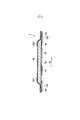
- 2 is a cross-sectional view taken along line F1-F1 'shown in FIG.
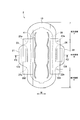
- FIG. 3 is a plan view of the absorbent article 2 according to the second embodiment.
- 4 is a cross-sectional view taken along line F3-F3 'shown in FIG.
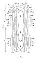
- FIG. 5 is a plan view of the absorbent article 3 according to the third embodiment.
- 6 is a cross-sectional view taken along line F5-F5 'shown in FIG.
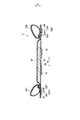
- FIG. 7 is a plan view of the absorbent article 4 according to the fourth embodiment.
- 8 is a cross-sectional view taken along line F7F-F7F 'shown in FIG.
- FIG. 9 is a cross-sectional view taken along line F7M-F7M 'shown in FIG. 10 is a cross-sectional view taken along line F7R-F7R 'shown in FIG.
- FIG. 11 is sectional drawing which shows the modification of the leak-proof part of 4th Embodiment.
- FIG. 12 is a cross-sectional view showing a modified example of the leakage preventing part of the fourth embodiment.
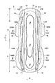
- FIG. 13 is a plan view of the absorbent article 5 according to the fifth embodiment.
- 14 is a cross-sectional view taken along line F13A-F13A 'shown in FIG. 15 is a cross-sectional view taken along line F13B-F13B ′ shown in FIG.
- FIG. 1 is a plan view of an absorbent article 1 according to the embodiment.
- 2 is a cross-sectional view taken along line F1-F1 ′ shown in FIG.
- the absorbent article 1 is a sanitary napkin, for example.
- the absorbent article 1 has a front region F, a central region M, and a rear region R.
- the central region M contacts the skin surface around the wearer's vaginal opening.
- the front region F is in contact with the skin surface on the front side (abdomen side) of the wearer than the center region.
- the rear region R is in contact with the skin surface on the back side (back side) of the wearer than the center region.
- the absorbent article 1 includes a top sheet 10 that comes into contact with the wearer's skin, a liquid-impermeable back sheet 20 that does not transmit liquid, and an absorber 30.
- the top sheet 10 is provided with a pair of side sheets 201 and 202 having a predetermined interval in the width direction of the absorbent article 1 and extending in the longitudinal direction of the absorbent article 1.
- the absorbent article 1 has a fixing region for fixing to the underwear of the wearer on the surface opposite to the skin side of the wearer of the back sheet 20.
- the fixed region is a region where an adhesive, an adhesive tape, a hook-and-loop fastener, or the like is disposed.
- region where the adhesive material for a wearer to fix the absorbent article 1 to underwear was coated is shown. Therefore, hereinafter, the fixing area is referred to as fixing areas 101 and 102 in which the adhesive material 100 is disposed.
- the adhesive 100 is a hot-melt adhesive material that can be easily applied in an arbitrary pattern.
- the hot melt adhesive material is composed of a styrene polymer, a tackifier, and a plasticizer.
- styrene polymer styrene-ethylene-butylene-styrene block copolymer, styrene-butadiene-styrene block copolymer, styrene-isobutylene-styrene block copolymer, and the like can be used.
- a styrene-ethylene-butylene-styrene block copolymer was used.
- the pressure-sensitive adhesive material is not limited to those described above, but a room temperature pressure-sensitive hot melt adhesive (HotelMelte Adhesive) that is soft and can be stuck between and attached to the fibers of the adherend at room temperature can be used.
- HotelMelte Adhesive room temperature pressure-sensitive hot melt
- the fixed areas 101 and 102 are indicated by broken lines in FIG. As shown in FIG. 1, the region corresponding to the fixed region 101 and the region corresponding to the side sheet 201 partially overlap each other in the thickness direction of the absorbent article 1. The area corresponding to the fixed area 102 and the area corresponding to the side sheet 202 partially overlap each other.
- the adhesive material 70 is apply
- the top sheet 10 is a nonwoven fabric.
- the material of the top sheet 10 is not particularly limited as long as it is a sheet-like material having a structure that allows liquid to permeate, such as a woven fabric or a perforated plastic sheet. Either natural fibers or chemical fibers can be used as the woven or non-woven material.
- thermoplastic hydrophobic chemical fibers examples include single fibers such as polyethylene (PE), polypropylene (PP), and polyethylene terephthalate (PET), fibers formed by graft polymerization of polyethylene and polypropylene, and composite fibers such as a core-sheath structure. Can be mentioned.
- any one of a dry method (a card method, a spun bond method, a melt blown method, an airlaid method, etc.) and a wet method can be used.
- a plurality of methods may be combined among the dry method and the wet method.
- methods, such as thermal bonding, needle punching, and chemical bonding are mentioned.
- the method for producing the nonwoven fabric is not limited to the above-described method.
- a spunlace formed into a sheet shape by a hydroentanglement method can be used for the top sheet 10.
- corrugation to the upper layer side of the nonwoven fabric, or the uneven nonwoven fabric which provided the fabric weight unevenness to the nonwoven fabric by applying air at the time of web formation can also be used for the surface sheet 10. By forming irregularities on the surface, it is possible to reduce diffusion of body fluid through the surface of the topsheet 10 before passing through the topsheet 10.
- the back sheet 20 uses a film mainly composed of polyethylene, polypropylene, etc., a breathable resin film, a spunbond, or a sheet in which a breathable resin film is bonded to a nonwoven fabric such as spunlace. Can do.
- the back sheet 20 is preferably made of a material having flexibility that does not cause a sense of incongruity when worn.
- LDPE low density polyethylene
- the absorber 30 includes hydrophilic fibers and pulp.
- hydrophilic fibers include pulverized pulp, cellulose such as cotton, regenerated cellulose such as rayon and fibril rayon, semi-synthetic cellulose such as acetate and triacetate, particulate polymer, fibrous polymer, thermoplastic hydrophobic chemical fiber, or A thermoplastic hydrophobic chemical fiber or the like subjected to hydrophilic treatment can be used alone or in combination. Among these, it is preferable to use pulverized pulp in consideration of low cost and ease of forming the absorber.
- a material obtained by mixing a polymer absorbent with a hydrophilic fiber may be used as the absorber 30.
- the polymer absorber is a granular polymer such as a sodium acrylate copolymer having absorbency and hygroscopicity.
- the absorber 30 may be an airlaid sheet obtained by forming hydrophilic fibers or powder into a sheet shape by the airlaid method.
- the thickness of the air laid sheet is preferably 0.3 to 5.0 mm.
- a fiber and particulate polymer formed into a sheet with a binder or the like can be cited.
- the particulate polymer may be dispersed in layers in the airlaid sheet, or may be biased in the thickness direction.
- Embossing may be formed on the absorber 30 in order to prevent loss of shape and twist while wearing, or to adjust the thickness.
- Embossing to the absorber 30 can be formed by passing the absorber between a patterned embossing roll and a flat roll.
- a patterned embossing roll As the pattern of the embossing roll, a lattice shape, a dot shape, a wave shape, or the like is used.
- the side sheets 201 and 202 are disposed on both sides of the absorber 30 on the surface of the top sheet 10.
- One end portion in the longitudinal direction of the side sheet 201 is substantially straight and overlaps with one end portion in the longitudinal direction of the topsheet 10.
- the other end in the longitudinal direction of the side sheet 201 matches the shape of a part of the outer periphery of the top sheet 10 and the back sheet 20.
- the top sheet 10 and the side sheets 201 and 202 constitute a contact surface with the skin. That is, in the present embodiment, the side sheets 201 and 202 constitute a leak-proof portion that prevents body fluid that travels on the surface of the top sheet 10 from leaking to the outside of the absorbent article 1.
- the absorbent article 1 includes an area corresponding to the side sheets 201 and 202 functioning as a leak-proof portion and an area corresponding to the fixed areas 101 and 102 fixed to the underwear. In plan view, they overlap each other. In the center region corresponding to the wearer's crotch, the absorbent article 1 is particularly liable to slip or shift in the front-rear direction.
- the absorbent article 1 and the undergarment can be securely fastened in the central region M, and the body fluid that travels on the surface of the topsheet 10 is absorbed in the central region M. It is possible to prevent leakage to the outside of the property article 1.
- FIG. 3 is a plan view of the absorbent article 2 according to the embodiment. 4 is a cross-sectional view taken along line F3-F3 ′ shown in FIG.
- the absorbent article 2 and the absorbent article 1 have different shapes. The same components as those in the first embodiment are denoted by the same reference numerals and detailed description thereof is omitted.
- the back sheet 20 has a central wing part 21 and a central wing part 22.
- a pair of the central wing part 21 and the central wing part 22 are formed at corresponding positions in the width direction of the absorbent article 2.
- the central wing part 21 and the central wing part 22 are extended in the width direction of the absorbent article 2 in the central region M.
- the width of the central region M of the back sheet 20 is larger than the widths of the front region F and the rear region R.
- the absorbent article 2 includes separate leak-proof portions 203 and 204 different from the side sheets. Leakproof portions 203 and 204 are disposed on both sides of the topsheet 10.
- the central wing portion 21 has a root portion 21a that is a mounting position on the absorbent article 2.
- the root portion 21 a is connected to a position where the width of the absorbent article 2 is the narrowest.
- the leak-proof portion 203 extends to the outside in the width direction of the absorbent article 2 from the root portion 21a.
- the leak-proof portion 203 is preferably bonded to the surface of the top sheet 10 on the skin side of the wearer at the joint portion 23 provided in the vicinity of the base portion 21a.
- the central wing portion 22 has a root portion 22a that is an attachment position to the absorbent article 2.
- the root portion 22a is connected to a position where the width of the absorbent article 2 is the narrowest.
- the leak-proof portion 204 extends outward in the width direction of the absorbent article 2 from the root portion 22a.
- the leak-proof portion 204 is preferably bonded to the surface of the face sheet 10 on the skin side of the wearer at the joint portion 24 provided in the vicinity of the base portion 22a.
- the center wing portions 21 and 22 are folded back to the crotch portion of the underwear, whereby the fixing regions 103 and 104 are bonded to the crotch portion of the underwear. Therefore, the center region M and the undergarment of the absorbent article 2 can be securely fastened, and in the center region M, body fluid that travels on the surface of the topsheet 10 can be prevented from leaking to the outside of the absorbent article 2. .
- fixing regions 103 and 104 to which the adhesive 100 is applied are formed on the surface of the central wing portions 21 and 22 opposite to the skin side of the wearer.
- the absorbent article 2 can be stabilized at a predetermined position of the underwear when the absorbent article 2 is mounted by disposing the fixing regions 103 and 104 in the portion corresponding to the leak-proof portion. Therefore, it is possible to prevent the absorbent article 2 from being worn in a state where it is rolled up.
- the leak-proof parts 203 and 204 are joined to the topsheet 10 by the joint parts 23 and 24, the leak-proof parts 203 and 204 are opposite to the contact surface with the skin of the wearer of the underwear when worn. It is possible to prevent the deformation that falls to the side.
- FIG. 5 is a plan view of the absorbent article 3 according to the embodiment. 6 is a cross-sectional view taken along line F5-F5 ′ shown in FIG.
- the absorbent article 3 and the absorbent article 1 have different shapes. The same components as those in the first and second embodiments are denoted by the same reference numerals and detailed description thereof is omitted.
- the absorbent article 3 shown in FIG. 5 has a front region F, a central region M, and a rear region R.
- the central region M contacts the skin surface around the wearer's vaginal opening.
- the front region F is in contact with the skin surface on the front side (abdomen side) of the wearer than the center region.
- the rear region R is in contact with the skin surface on the back side (back side) of the wearer than the center region.
- the absorbent article 3 is a sanitary napkin having a structure in which the rear region R of the absorbent article 1 is expanded rearward.
- the absorbent article 3 includes a top sheet 10 that comes into contact with the wearer's skin, a liquid-impermeable back sheet 20 that does not transmit liquid, and an absorber 30.
- the top sheet 10 is provided with a pair of side sheets 41 and 42 having a predetermined interval in the width direction of the absorbent article 3 and extending in the longitudinal direction of the absorbent article 3.
- the absorbent article 3 includes gathers 205 and 206 and a wing part 60.
- the gathers 205 and 206 are provided on both side edge portions 31 of the absorbent body 30 in a region including the central region M of the absorbent article 3.
- the gathers 205 and 206 manufactured as separate bodies are disposed at predetermined positions.
- the wing part 60 is provided outside the absorbent article 3 in the width direction of the absorbent article 3, and extends outward in the width direction of the absorbent body 30.
- the gathers 205 and 206 constitute a leakage preventing part.
- the wing part 60 is constituted by the back sheet 20 and the side sheets 41 and 42.
- the wing part 60 is formed of a liquid-impermeable material.
- the wing part 60 is folded back to the crotch part (crotch part) of the underwear, and is provided on the wearer's rear side with respect to the central wing parts 61f and 62f that are fixed to the underwear, and the central wing parts 61f and 62f, and has a shape of the underwear And the rear wing portions 61r and 62r extending outward in the width direction of the absorbent article 3.
- the central wing portions 61f and 62f extend outward in the width direction of the absorber 30 in the central region M.
- the central wing portions 61f and 62f have root portions 61a and 62a connected to a position where the width of the absorbent article 3 is the narrowest.
- the rear wings 61r and 62r extend outward in the width direction of the absorber 30 in the rear region R on the rear side of the central wing portions 61f and 62f.
- the absorbent article 3 has fixing regions 105 and 106 in which the adhesive 100 is disposed on the surface of the central wing portion 60 opposite to the wearer's skin side of the back sheet 20.
- the fixed areas 105 and 106 are indicated by broken lines in FIG.
- the region corresponding to the fixed region 105 and the region corresponding to the gather 205 partially overlap each other.
- the area corresponding to the fixed area 106 and the area corresponding to the gather 206 partially overlap each other.
- the adhesive material 70 is apply
- the adhesive material 70 is applied in a plurality of lines along the longitudinal direction of the back sheet 20.
- the gathers 205 and 206 are formed of a nonwoven fabric or an apertured film. In the present embodiment, the gathers 205 and 206 are different sheets different from the top sheet 10 and the side sheets 41 and 42. The gathers 205 and 206 are disposed at least in the central region M of the absorbent article 3.
- the gathers 205 and 206 rise in a direction away from the topsheet 10 in the thickness direction (hereinafter, standing direction T) during use (when worn). That is, it stands up toward the wearer's skin side. Thereby, the gathers 205 and 206 prevent the wearer's body fluid from leaking from the absorbent article 3.
- the gather 205 is formed on the surface of the skin side of the wearer in the fixed end 221 joined to the topsheet 10 at positions corresponding to the edges on both sides in the width direction of the absorber 30 and the central wing portion 61f. And a central wing joint 231 to be joined.
- the fixing region 105 is formed at a position facing the gather 205 in the thickness direction of the absorbent article.
- the gather 206 is joined to the surface of the wearer's skin side in the fixed end 222 joined to the topsheet 10 at positions corresponding to the edges on both sides in the width direction of the absorbent body 30 and the center wing portion 62f.
- the fixing region 106 is formed at a position facing the gather 206 in the thickness direction of the absorbent article.
- the absorbent article 3 when the central wing portion 61f is folded back to the crotch portion of the underwear and the fixing regions 105 and 106 are bonded to the crotch portion of the underwear, the surfaces at the central wing joint portions 231 and 232 The gathers 205 and 206 joined to the sheet 10 are fixed in a state of being opened outward in the width direction. Therefore, the center region M of the absorbent article 3 and the underwear can be secured.
- the contraction force of the gather works in the longitudinal direction of the absorbent article. For this reason, there is a tendency that the gathers are lifted due to the shrinkage of the gathers and the absorbent article is pulled away from the underwears after being locked to the underwears during use and before the underwears are pulled up and attached.
- the absorbent article 3 includes the fixing regions 105 and 106 at positions corresponding to the gathers 205 and 206, and is bonded to the topsheet 10 by the central wing bonding portions 231 and 232, and thus described above.
- the absorbent article 3 can be reliably fastened to the appropriate position of underwear.
- FIG. 7 is a plan view of the absorbent article 4 according to the embodiment. 8 is a cross-sectional view taken along line F7F-F7F ′ shown in FIG. 9 is a cross-sectional view taken along line F7M-F7M ′ shown in FIG. 10 is a cross-sectional view taken along line F7R-F7R ′ shown in FIG.
- the absorbent article 4 and the absorbent article 3 differ in the form of gathers.
- the same components as those in the first to third embodiments are denoted by the same reference numerals and detailed description thereof is omitted.
- the absorbent article 4 has gathers 207 and 208.
- the gathers 207 and 208 are disposed on the top sheet 10 and have a predetermined interval in the width direction of the absorbent article 4 and extend in the longitudinal direction of the absorbent article 4.
- the gathers 207 and 208 extend from the front region F to the rear region R.
- the gathers 207 and 208 constitute a leakage preventing portion.
- the absorbent article 4 includes front wing parts 63 and 64, central wing parts 65 and 66, and rear wing parts 67 and 68.
- Each wing portion is constituted by a back sheet 20 and side sheets 41 and 42.
- Each wing is formed of a liquid-impermeable material.
- the front wing parts 63 and 64 are provided on the front side of the wearer from the central wing parts 65 and 66.
- the center wing parts 65 and 66 are folded back to the crotch part (the crotch part) of the underwear and stopped by the underwear.
- the rear wing portions 67 and 68 are provided on the rear side of the wearer relative to the central wing portions 65 and 66, and extend outward in the width direction of the absorbent article 4 along the shape of the underwear.
- the gathers 207 and 208 may be disposed at predetermined positions after being manufactured as separate bodies, or may be formed integrally with a sheet constituting the wing portion.
- seat which comprises a wing part is folded back and formed.
- Adhesive 100 is disposed in the fixing regions 107F and 108F on the surface of the front wings 63 and 64 opposite to the skin side of the wearer of the back sheet 20.
- the fixed areas 107F and 108F are indicated by broken lines in FIG.
- the region corresponding to the fixed region 107 ⁇ / b> F and the region corresponding to the gather 207 partially overlap each other.
- the area corresponding to the fixed area 108F and the area corresponding to the gather 208 partially overlap each other.
- the gather 207 includes a fixed end 223 that is joined to the topsheet 10 at positions corresponding to both edges in the width direction of the absorbent body 30, and a front wing that is joined to the skin side surface of the wearer in the front wing portion 63. And a joint portion 233F.
- the gather 208 has a fixed end 224 joined to the topsheet 10 at positions corresponding to both side edges of the absorbent body 30 in the width direction, and a front wing joined to the skin side surface of the wearer in the front wing 64.
- a joint portion 234F In plan view of the absorbent article 4, the region corresponding to the fixed region 107F and the region corresponding to the front wing joint 233F overlap each other. The region corresponding to the fixed region 108F and the region corresponding to the front wing joint 234F overlap each other.
- the adhesive 100 is disposed in the fixing regions 107M and 108M on the surface of the central wings 65 and 66 opposite to the wearer's skin side of the back sheet 20.
- the fixed areas 107M and 108M are indicated by broken lines in FIG.
- FIG. 7 in a plan view of the absorbent article 4, the region corresponding to the fixed region 107 ⁇ / b> M and the region corresponding to the gather 207 partially overlap each other.
- the area corresponding to the fixed area 108M and the area corresponding to the gather 208 partially overlap each other.
- the gather 207 includes a fixed end 223 joined to the topsheet 10 at positions corresponding to both side edges of the absorbent body 30 in the width direction, and a center wing joined to the skin side surface of the wearer in the center wing 65. And a joint portion 233M.
- the gather 208 includes a fixed end 224 joined to the topsheet 10 at positions corresponding to both edges in the width direction of the absorbent body 30, and a center wing joined to the skin side surface of the wearer in the center wing portion 66. And a joint portion 234M.
- the adhesive 100 is disposed on the fixing regions 107R and 108R on the surface of the rear wings 67 and 68 opposite to the skin side of the wearer of the back sheet 20.
- the fixed regions 107R and 108R are indicated by broken lines in FIG.
- the region corresponding to the fixed region 107 ⁇ / b> R and the region corresponding to the gather 207 overlap each other.
- the area corresponding to the fixed area 108R and the area corresponding to the gather 208 overlap each other.
- the gather 207 includes a fixed end 223 joined to the topsheet 10 at positions corresponding to both edges of the absorbent body 30 in the width direction, and a back wing joined to the skin side surface of the wearer in the back wing 67. And a joint portion 233R.
- the gather 208 includes a fixed end 224 joined to the topsheet 10 at positions corresponding to both edges in the width direction of the absorbent body 30 and a back wing joined to the surface of the wearer's skin in the back wing 68.
- a joint portion 234R The region corresponding to the fixed region 107R partially overlaps the region corresponding to the rear wing joint 233R. The region corresponding to the fixed region 108R partially overlaps the region corresponding to the central wing joint 234M.
- an adhesive 70 is applied in a line along the longitudinal direction of the back sheet 20 on the surface of the back sheet 20 that comes into contact with the wearer's underwear (not shown in FIG. 7, see FIGS. 8 to 10). ).
- the adhesive material 70 is applied in a plurality of lines along the longitudinal direction of the back sheet 20.
- the central wing portions 65 and 66 are folded back to the surface opposite to the skin side of the underwear and 107 M and 108 M are adhered, and the front wing portions 63 and 64 and the rear wing portion
- the gathers 207 and 208 are fixed in a state of being opened outward in the width direction. Therefore, the gathers 207 and 208 do not fall toward the absorption surface, and the planar state can be maintained until the gathers 207 and 208 are mounted.
- the gathers 207 and 208 can be prevented from falling toward the absorption surface, and the absorption surface can be secured. Accordingly, it is possible to secure the central region M and the undergarment of the absorbent article 4 and to prevent the body fluid that travels on the surface of the topsheet 10 from leaking outside the absorbent article 4 in the central region M.
- the gathers 207 and 208 are joined to the seat portion constituting the wing portion by the central wing joint portions 233M and 234M, the front wing joint portions 233F and 234F, and the rear wing joint portions 233R and 234R. It is possible to prevent the gathers 207 and 208 from floating from the seat portion constituting the wing portion between the time when the absorbent article 4 is locked to the underwear and before the underwear is pulled up and attached. Moreover, since it can prevent that the absorbent article 4 leaves
- the gathers are arranged so as to partially face each other in the area (fixed area) where the adhesive formed on the surface opposite to the skin side of the wearer of the back sheet is arranged and in the thickness direction of the absorbent article. It only has to be. Therefore, the cross-sectional shape of the gather is not limited to the examples shown in FIGS.
- the gather shown as a modified example is formed over the front area F to the rear area R, as in FIG. Therefore, the examples shown in FIGS. 8 to 10 can be applied to the position of the joint between the gather and the top sheet in the front region F to the rear region R and the folded shape of the gather. Therefore, in the modification, only a representative location, a cross-sectional shape in the central region M (F7M-F7M ′ line shown in FIG. 7) will be described.
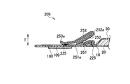
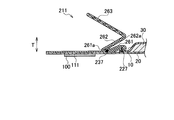
- 11 and 12 are cross-sectional views of gathers shown as modified examples.
- the gather 209 shown in FIG. 11 has a fixed end 225, a first leak-proof surface 251, a second leak-proof surface 252, and a third leak-proof surface 253.
- the gathers 209 are joined to the topsheet 10 at positions corresponding to the edges on both sides in the width direction of the absorber 30 at the fixed end 225.
- the first leak-proof surface 251 extends from the fixed end 225 toward the outer side in the width direction of the absorbent article.
- the second leak-proof surface 252 is folded at the end 251a of the first leak-proof surface 251 and extends toward the inner side in the width direction of the absorbent article.
- the third leak-proof surface 253 extends from the end 252a of the second leak-proof surface 252 toward the outer side in the width direction of the absorbent article.
- the gather 209 has a joint part 235 joined to the top sheet 10 at the end 253a of the third leak-proof surface 253.
- the fixing region 109 in which the adhesive 100 is disposed and the gather 209 are disposed at positions that partially overlap each other.
- the fixed region 109 is disposed at a position overlapping the joint 235.
- the gather 211 shown in FIG. 12 has a fixed end 227, a first leak-proof surface 261, a second leak-proof surface 262, and a third leak-proof surface 263.
- the gathers 211 are joined to the topsheet 10 at positions corresponding to the edges on both sides in the width direction of the absorbent body 30 at the fixed end 227.
- the first leak-proof surface 261 extends from the fixed end 227 toward the outer side in the width direction of the absorbent article.
- the gather 211 has a joint portion 237 that is joined to the top sheet 10 at the end portion 261 a of the first leak-proof surface 261.
- the second leak-proof surface 262 is folded at the end 261a of the first leak-proof surface 261 and extends toward the inner side in the width direction of the absorbent article.
- the third leak-proof surface 263 extends from the end 262a of the second leak-proof surface 262 toward the outer side in the width direction of the absorbent article.
- the fixing region 111 in which the adhesive 100 is disposed and the gather 211 are disposed at positions that partially overlap each other.
- the fixed region 111 and a part of the third leak-proof surface 263 are arranged at positions that overlap each other.
- FIG. 13 is a plan view of the absorbent article 5 according to the embodiment. 14 is a cross-sectional view taken along line F13A-F13A ′ shown in FIG. 15 is a cross-sectional view taken along line F13B-F13B ′ shown in FIG.
- the absorbent article 5 and the absorbent article 4 differ in the form of gathers.
- the same components as those in the first to fourth embodiments are denoted by the same reference numerals and detailed description thereof is omitted.
- the absorbent article 5 has gathers 213 and 214.
- the gathers 213 and 214 are disposed on the top sheet 10, have a predetermined interval in the width direction of the absorbent article 5, and extend in the longitudinal direction of the absorbent article 5.
- the gathers 213 and 214 extend from the front region F to the rear region R.
- the gathers 213 and 214 constitute a leakage preventing part.
- the adhesive 100 is disposed in the fixing regions 109M and 110M on the surface of the central wings 65 and 66 opposite to the wearer's skin side of the back sheet 20.
- the fixed areas 109M and 110M are indicated by broken lines in FIG.
- FIG. 13 in the plan view of the absorbent article 5, the region corresponding to the fixed region 109 ⁇ / b> M and the region corresponding to the gather 213 partially overlap each other.
- the area corresponding to the fixed area 110M and the area corresponding to the gather 214 partially overlap each other.
- the gather 213 includes a fixed end 229 joined to the topsheet 10 at positions corresponding to both side edges of the absorbent body 30 in the width direction, and a center wing joined to the skin side surface of the wearer in the center wing portion 65. And a joint portion 239M.
- a loop portion is formed between the fixed end 229 and the central wing joint portion 239M, and a hollow portion AR is formed.
- the gather 214 has a fixed end 230 that is joined to the topsheet 10 at positions corresponding to both edges in the width direction of the absorbent body 30 and a center wing that is joined to the skin side surface of the wearer in the center wing 66. And a junction 240M.
- a loop shape is formed between the fixed end 230 and the central wing joint 240M, and a hollow portion AR is formed.
- the adhesive 100 is disposed on the fixing regions 109R and 110R on the surface of the rear wing portions 67 and 68 opposite to the skin side of the wearer of the back sheet 20.
- the fixed regions 109R and 110R are indicated by broken lines in FIG.
- FIG. 13 in a plan view of the absorbent article 5, the region corresponding to the fixed region 109 ⁇ / b> R and the region corresponding to the gather 213 overlap each other.
- the area corresponding to the fixed area 110R and the area corresponding to the gather 214 overlap each other.
- the gather 213 has a fixed end 229 joined to the topsheet 10 at positions corresponding to both edges in the width direction of the absorbent body 30, and the wearer's skin side in the rear wing portion 67. And a rear wing joint 239R joined to the surface. A loop is formed between the fixed end 229 and the rear wing joint 239R, and a hollow part AR is formed.
- the gather 214 has a fixed end 230 that is joined to the topsheet 10 at positions corresponding to both edges in the width direction of the absorbent body 30, and the wearer's skin side in the rear wing portion 68. And a rear wing joint 240R joined to the surface.
- a loop shape is formed between the fixed end 230 and the rear wing joint 240R, and a hollow portion AR is formed.
- an adhesive 70 is applied in a line along the longitudinal direction of the back sheet 20 on the surface of the back sheet 20 that comes into contact with the wearer's underwear (not shown in FIG. 13, see FIGS. 14 and 15). ).
- the adhesive material 70 is applied in a plurality of lines along the longitudinal direction of the back sheet 20.
- the central wing portions 65 and 66 are folded back to the surface opposite to the skin side of the underwear and the 109M and 110M are adhered, and the front wing portions 63 and 64 and the rear wing portion
- the gathers 207 and 208 are fixed in a state of being opened outward in the width direction. Therefore, the gathers 213 and 214 do not fall toward the absorption surface, and the planar state can be maintained until the gathers are attached.
- the gathers 213 and 214 can be prevented from falling toward the absorption surface, and the absorption surface can be secured. Therefore, it is possible to secure the central region M and the undergarment of the absorbent article 5 and to prevent body fluid that travels on the surface of the topsheet 10 from leaking to the outside of the absorbent article 5 in the central region M.
- the absorbent article 5 since the gathers 213 and 214 are joined to the seat portion constituting the wing portion by the central wing joint portions 239M and 240M and the rear wing joint portions 239R and 240R, the absorbent article 5 is related to the underwear. It is possible to prevent the gathers 213 and 214 from floating from the seat portion constituting the wing portion between the stop and the time when the underwear is pulled up and attached. Moreover, since it can prevent that the absorbent article 5 leaves
- the embodiment can be changed as follows.
- the absorbent article 1 has been described as being a sanitary napkin, the absorbent article 1 is not limited thereto, and may be an incontinence pad, a panty liner, a disposable diaper, or the like.
- a string-like body having stretchability in the longitudinal direction may be provided in the gather along the longitudinal direction.
- the material itself constituting the gathers may have elasticity.
- the gather shape and folding method may be other than those described in the above-described embodiments.
- the fixed ends of the gathers are joined to the topsheet 10 at positions corresponding to the edges on both sides of the absorbent body 30 in the width direction.
- the fixed end may be joined at a position overlapping the edge of the absorber 30.
- an absorbent article that can prevent body fluid from leaking out from the central region by securely fastening the absorbent article and the undergarment.
Landscapes
- Health & Medical Sciences (AREA)
- Epidemiology (AREA)
- Heart & Thoracic Surgery (AREA)
- Engineering & Computer Science (AREA)
- Biomedical Technology (AREA)
- Vascular Medicine (AREA)
- Life Sciences & Earth Sciences (AREA)
- Animal Behavior & Ethology (AREA)
- General Health & Medical Sciences (AREA)
- Public Health (AREA)
- Veterinary Medicine (AREA)
- Fluid Mechanics (AREA)
- Physics & Mathematics (AREA)
- Absorbent Articles And Supports Therefor (AREA)
Abstract
吸収性物品1は、着用者の肌に当接する表面シート10と、液体を透過しない液不透過性の裏面シート20と、吸収体30とを有する。表面シート10には、吸収性物品1の幅方向所定の間隔を有し、吸収性物品1の長手方向に延在する一対のサイドシート201,202が配設される。吸収性物品1は、裏面シート20の着用者の肌側とは反対の表面に、着用者の下着に固定する固定領域101,102を有する。吸収性物品1の厚み方向において、固定領域101とサイドシート201とは互いに部分的に対向して配置される。固定領域102とサイドシート202とは互いに部分的に対向して配置される。
Description
着用者の肌に当接する当接面を有する表面シートと、液体を透過しない液不透過性の裏面シートと、前記表面シートと前記裏面シートとの間に設けられる吸収体とを備える吸収性物品に関する。
従来、生理用ナプキンやパンティライナーなどの吸収性物品は、着用者の前側(腹側)から後ろ側(背中側)に延びる縦長の形状を有する。一般的に、吸収性物品は、液透過性の表面シートと、液不透過性の裏面シートと、表面シートと裏面シートとの間に設けられる吸収体とを備える。
このような吸収性物品のなかには、体液が吸収性物品から漏れ出ることを防止するギャザー(防漏部)が設けられるものもある。ギャザーは、吸収性物品の長手方向に沿って設けられており、下着へ装着した状態で、着用者の股下に対応する中央領域において、着用者の肌方向に立ち上がる形状を有する。これにより、中央領域において、着用者の肌と吸収性物品との密着性が高められている。
しかし、上述した従来の吸収性物品には、次のような問題点が考えられる。すなわち、着用者の動きによっては、中央領域における吸収性物品と下着との留め付けが不十分になることがあった。
生理用ナプキンのような吸収性物品では、着用者の動きに合わせて、吸収性物品と下着とが中央領域において互いに前後方向にずれないこと、或いは吸収性物品が下着から離れないことが望まれる。
第1の特徴に係る吸収性物品は、着用者の肌に当接する当接面を有する表面シートと、液体を透過しない液不透過性の裏面シートと、前記表面シートと前記裏面シートとの間に設けられる吸収体とを備える。吸収性物品は、前記表面シートに配設されており、前記吸収性物品の幅方向に所定の間隔を有し前記吸収性物品の長手方向に延在する一対の防漏部(サイドシート201,202)と、前記裏面シートの前記着用者の肌側とは反対の表面に配置され、前記吸収性物品を前記着用者の下着に固定する固定領域(接着材100,固定領域101,102)とを有する。前記吸収性物品の平面視において、前記固定領域に対応する領域と前記防漏部に対応する領域とは、互いに部分的に重なる。
実施形態に係る吸収性物品について、図面を参照しながら説明する。具体的には、第1~第5実施形態について説明する。
なお、以下の図面の記載において、同一または類似の部分には、同一または類似の符号を付している。ただし、図面は模式的なものであり、各寸法の比率などは現実のものとは異なることに留意すべきである。したがって、具体的な寸法などは以下の説明を参酌して判断すべきものである。また、図面相互間においても互いの寸法の関係や比率が異なる部分が含まれていることは勿論である。
(第1実施形態)
図1及び図2を参照して、第1実施形態に係る吸収性物品1について説明する。図1は、実施形態に係る吸収性物品1の平面図である。図2は、図1に示すF1-F1’線における断面図である。
図1及び図2を参照して、第1実施形態に係る吸収性物品1について説明する。図1は、実施形態に係る吸収性物品1の平面図である。図2は、図1に示すF1-F1’線における断面図である。
図1に示す吸収性物品1は、例えば、生理用ナプキンである。図1に示すように、吸収性物品1は、前方領域Fと中央領域Mと後方領域Rとを有する。中央領域Mは、着用者の膣口周辺の肌表面に接触する。前方領域Fは、中央領域よりも着用者の前方側(腹側)の肌表面に接触する。後方領域Rは、中央領域よりも着用者の後方側(背側)の肌表面に接触する。
吸収性物品1は、着用者の肌に当接する表面シート10と、液体を透過しない液不透過性の裏面シート20と、吸収体30とを有する。表面シート10には、吸収性物品1の幅方向所定の間隔を有し、吸収性物品1の長手方向に延在する一対のサイドシート201,202が配設される。
吸収性物品1は、裏面シート20の着用者の肌側とは反対の表面に、着用者の下着に固定する固定領域を有する。ここで、固定領域とは、接着材、接着テープ、面ファスナーなどが配置される領域である。本実施形態では、着用者が吸収性物品1を下着に固定するための接着材が塗工された領域を示す。したがって、以下では、固定領域を接着材100が配置された固定領域101,102という。
なお、本実施形態では、接着材100は、任意のパターンで容易に塗布できるホットメルト粘着材を使用する。ホットメルト粘着材は、スチレン系ポリマー、粘着付与剤、可塑剤から構成される。スチレン系ポリマーとしては、スチレン-エチレン-ブチレン-スチレンブロック共重合体、スチレン-ブタジエン-スチレンブロック共重合体、スチレン-イソブチレン-スチレンブロック共重合体、などを用いることができる。本実施形態では、スチレン-エチレン-ブチレン-スチレンブロック共重合体を使用した。粘着材は上記のものに限られないが、柔らかく、常温で被着体の繊維と繊維の間にめり込んで付着できる常温感圧性ホットメルト接着材(Hot Melt Adhesive)を使用することができる。
固定領域101,102は、図1において、破線で示される。図1に示すように、吸収性物品1の厚み方向において、固定領域101に対応する領域とサイドシート201に対応する領域とは互いに部分的に重なっている。固定領域102に対応する領域とサイドシート202に対応する領域とは互いに部分的に重なっている。また、着用者の下着と接触する裏面シート20の表面には、裏面シート20の長手方向に沿って接着材70がライン状に塗布される(図1には不図示、図2参照)。接着材70は、裏面シート20の長手方向に沿って複数ライン塗布される。
本実施形態において、表面シート10は、不織布である。表面シート10の素材は、織布、有孔プラスチックシート等、液体を透過する構造のシート状の材料であれば、特に限定されない。織布や不織布の素材としては、天然繊維、化学繊維のいずれも使用できる。
天然繊維の例としては、粉砕パルプ、コットン等のセルロースが挙げられる。化学繊維の例としては、レーヨン、フィブリルレーヨン等の再生セルロース、アセテート、トリアセテート等の半合成セルロース、熱可塑性疎水性化学繊維、又は親水化処理を施した熱可塑性疎水性化学繊維などが挙げられる。熱可塑性疎水性化学繊維の例としては、ポリエチレン(PE)、ポリプロピレン(PP)、ポリエチレンテレフタレート(PET)等の単繊維、ポリエチレンとポリプロピレンをグラフト重合してなる繊維、芯鞘構造等の複合繊維が挙げられる。
不織布のウェブフォーミング方法としては、乾式(カード法、スパンボンド法、メルトブローン法、エアレイド法等)及び湿式のいずれか一つの方法を用いることができる。乾式法と湿式法のうち、複数の方法を組み合わせてもよい。また、サーマルボンディング、ニードルパンチ、ケミカルボンディング等の方法が挙げられる。不織布を作成する方法は、上述の方法に限定されない。
また、水流交絡法によりシート状に形成したスパンレースを表面シート10に用いることもできる。また、不織布の上層側に凹凸を付けた不織布、又はウェブ形成時にエアーを当てることにより不織布に目付ムラを設けた凹凸不織布を表面シート10に用いることもできる。表面に凹凸を形成することにより、体液が表面シート10を透過する前に表面シート10の表面を伝わって拡散することを軽減できる。
次に、裏面シート20について具体的に説明する。
本実施形態において、裏面シート20は、ポリエチレン、ポリプロピレン等を主体としたフィルム、通気性の樹脂フィルム、スパンボンド、又はスパンレース等の不織布に通気性の樹脂フィルムが接合されたシートなどを用いることができる。裏面シート20は、着用時の違和感を生じさせない程度の柔軟性を有する材料とすることが好ましい。例えば、低密度ポリエチレン(LDPE)樹脂を主体とし、目付(単位面積当りの重さ(g))が15~30g/m2の範囲のフィルムを使用することが好ましい。
次に、吸収体30について具体的に説明する。
吸収体30は、親水性繊維、パルプを含む。親水性繊維の例としては、粉砕パルプ、コットン等のセルロース、レーヨン、フィブリルレーヨン等の再生セルロース、アセテート、トリアセテート等の半合成セルロース、粒子状ポリマー、繊維状ポリマー、熱可塑性疎水性化学繊維、又は、親水化処理を施した熱可塑性疎水性化学繊維等を単独又は混合して用いることができる。これらの中でも、低コストと吸収体の成形し易さとを考慮すると、粉砕パルプを使用することが好ましい。
親水性繊維に高分子吸収体を混合したものを吸収体30として使用しても良い。本実施形態では、高分子吸収体は、吸収性、吸湿性のあるアクリル酸ナトリウム共重合体等の粒状ポリマーである。
吸収体30は、親水性繊維又は粉体をエアレイド法によってシート状に成形したエアレイドシートでもよい。吸収体30として、エアレイドシートを使用する場合、エアレイドシートの厚さは、0.3~5.0mmであるのが好ましい。エアレイドシートの例としては、繊維と粒子状ポリマーとをバインダー等でシート物に成形したものが挙げられる。なお、粒子状ポリマーは、エアレイドシートにおいて、層状に分散されていてもよいし、厚み方向に偏っていてもよい。
吸収体30には、着用中の型崩れやヨレの防止、又は厚みを調整するため、エンボスが形成されていてもよい。吸収体30へのエンボスは、パターニングされたエンボスロールとフラットロールとの間に、吸収体を通紙することによって形成できる。エンボスロールのパターンは、格子状・ドット状・波状等が用いられるが、厚みを調整しやすい格子状のパターンが好ましい。
次に、サイドシート201,202について具体的に説明する。
サイドシート201,202は、表面シート10の表面であって、吸収体30の両側に配設される。サイドシート201の長手方向の一方の端部は、略直線であり、表面シート10の長手方向の一方の端部と重なる。サイドシート201の長手方向の他方の端部は、表面シート10及び裏面シート20の外周の一部の形状と一致する。
経血がサイドシート201,202を乗り越えて吸収性物品1外方へ流れることを防止するためには、疎水性又は撥水性を有することが好ましい。具体的には、スパンボンド不織布やSMS不織布などが挙げられる。表面シート10及びサイドシート201,202は、肌との当接面を構成する。すなわち、本実施形態において、サイドシート201,202は、表面シート10の表面を伝う体液が吸収性物品1の外側へ漏れることを防止する防漏部を構成する。
以上のように、吸収性物品1は、防漏部として機能するサイドシート201,202に対応する領域と、下着へ固定される固定領域101,102に対応する領域とが、吸収性物品1の平面視において、互いに重なっている。着用者の股下に対応する中央領域では、特に、吸収性物品1が縒れたり、前後方向にずれたりしやすい。これに対して、吸収性物品1によれば、中央領域Mにおける吸収性物品1と下着との留め付けを確実にすることができ、中央領域Mにおいて、表面シート10の表面を伝う体液が吸収性物品1の外側へ漏れることを防止できる。
(第2実施形態)
図3及び図4を参照して、第2実施形態に係る吸収性物品2について説明する。図3は、実施形態に係る吸収性物品2の平面図である。図4は、図3に示すF3-F3’線における断面図である。吸収性物品2と吸収性物品1とは形状が異なる。第1実施形態と同一の構成には、同一の番号を付けて詳細な説明を省略する。
図3及び図4を参照して、第2実施形態に係る吸収性物品2について説明する。図3は、実施形態に係る吸収性物品2の平面図である。図4は、図3に示すF3-F3’線における断面図である。吸収性物品2と吸収性物品1とは形状が異なる。第1実施形態と同一の構成には、同一の番号を付けて詳細な説明を省略する。
図3に示す吸収性物品2では、裏面シート20は、中央ウィング部21、中央ウィング部22を有する。中央ウィング部21と中央ウィング部22は、吸収性物品2の幅方向の対応する位置に一対形成される。中央ウィング部21と中央ウィング部22は、中央領域Mにおいて吸収性物品2の幅方向に延出されている。裏面シート20の中央領域Mの幅は、前方領域F及び後方領域Rの幅よりも大きい。
吸収性物品2は、サイドシートとは異なる別の防漏部203,204を備える。防漏部203,204は、表面シート10の両側に配設される。
中央ウィング部21は、吸収性物品2への取付位置である付け根部分21aを有する。吸収性物品2では、付け根部分21aは、吸収性物品2の幅が最も狭い位置に連結される。防漏部203は、付け根部分21aよりも吸収性物品2の幅方向外側に延出される。防漏部203は、付け根部分21aの近傍に設けられた接合部23において、表面シート10の着用者の肌側の表面に接着されていることが好ましい。
また、中央ウィング部22は、吸収性物品2への取付位置である付け根部分22aを有する。吸収性物品2では、付け根部分22aは、吸収性物品2の幅が最も狭い位置に連結される。防漏部204は、付け根部分22aよりも吸収性物品2の幅方向外側に延出される。防漏部204は、付け根部分22aの近傍に設けられた接合部24において、表面シート10の着用者の肌側の表面に接着されていることが好ましい。
中央ウィング部21及び中央ウィング部22における着用者の肌側とは反対の表面には、接着材100が塗布される固定領域103,104が形成される。防漏部203,204に対応する領域と、固定領域103,104に対応する領域とは、吸収性物品2の平面視において、互いに重なっている。中央ウィング部21,22は、下着のクロッチ部に折り返される。
以上のように、中央ウィング部21,22が下着のクロッチ部に折り返されることにより、固定領域103,104が下着のクロッチ部に接着される。従って、吸収性物品2の中央領域Mと下着との留め付けを確実にすることができ、中央領域Mにおいて、表面シート10の表面を伝う体液が吸収性物品2の外側へ漏れることを防止できる。
従来、吸収性物品2の防漏部203,204に相当する防漏部を備えた吸収性物品では、使用時に下着に係止されてから下着を引き上げて装着する間に、吸収性物品の側部及び防漏部着用者の脚部と摩擦することにより、下着の着用者の肌との当接面の反対側に捲れる力を受け易い。また、防漏部に連れて吸収性物品も不安定な状態で装着されてしまう可能性があった。
これに対して、吸収性物品2は、中央ウィング部21,22における着用者の肌側とは反対の表面には、接着材100が塗布される固定領域103,104が形成される。吸収性物品2は、防漏部に対応する部分に固定領域103,104が配置されることで、装着時に吸収性物品2を下着の所定位置に安定させることができる。従って、吸収性物品2が縒れた状態で装着されることを防止できる。
更に、防漏部203,204が接合部23,24により表面シート10に接合されている場合には、装着時に、防漏部203,204が下着の着用者の肌との当接面の反対側に捲れる変形を防止することができる。
(第3実施形態)
図5及び図6を参照して、第3実施形態に係る吸収性物品3について説明する。図5は、実施形態に係る吸収性物品3の平面図である。図6は、図5に示すF5-F5’線における断面図である。吸収性物品3と吸収性物品1とは形状が異なる。第1,第2実施形態と同一の構成には、同一の番号を付けて詳細な説明を省略する。
図5及び図6を参照して、第3実施形態に係る吸収性物品3について説明する。図5は、実施形態に係る吸収性物品3の平面図である。図6は、図5に示すF5-F5’線における断面図である。吸収性物品3と吸収性物品1とは形状が異なる。第1,第2実施形態と同一の構成には、同一の番号を付けて詳細な説明を省略する。
図5に示す吸収性物品3は、前方領域Fと中央領域Mと後方領域Rとを有する。中央領域Mは、着用者の膣口周辺の肌表面に接触する。前方領域Fは、中央領域よりも着用者の前方側(腹側)の肌表面に接触する。後方領域Rは、中央領域よりも着用者の後方側(背側)の肌表面に接触する。
吸収性物品3は、吸収性物品1の後方領域Rが後方に拡張された構造を有する生理用ナプキンである。吸収性物品3は、着用者の肌に当接する表面シート10と、液体を透過しない液不透過性の裏面シート20と、吸収体30とを有する。表面シート10には、吸収性物品3の幅方向に所定の間隔を有し、吸収性物品3の長手方向に延在する一対のサイドシート41,42が配設される。
吸収性物品3は、ギャザー205,206と、ウィング部60とを備える。ギャザー205,206は、吸収性物品3の中央領域Mを含む領域において、吸収体30の両側縁部31に設けられる。吸収性物品3では、別体として製造されたギャザー205,206を所定位置に配設する。ウィング部60は、吸収体30よりも吸収性物品3の幅方向の外側に設けられ、吸収体30の幅方向の外側に延出されている。本実施形態において、ギャザー205,206は、防漏部を構成する。
ウィング部60は、裏面シート20及びサイドシート41,42によって構成される。ウィング部60は、液不透過性の材料によって形成される。ウィング部60は、下着のクロッチ部(股下部)に折り返され、下着に止められる中央ウィング部61f,62fと、中央ウィング部61f,62fよりも着用者の後方側に設けられ、下着の形状に沿って吸収性物品3の幅方向の外側に延出する後方ウィング部61r,62rとによって構成される。
中央ウィング部61f,62fは、中央領域Mにおいて吸収体30の幅方向の外側に延出する。中央ウィング部61f,62fには、吸収性物品3の幅が最も狭い位置に連結される付け根部分61a,62aを有する。後方ウィング61r,62rは、中央ウィング部61f,62fよりも後方側の後方領域Rにおいて吸収体30の幅方向の外側に延出する。
吸収性物品3は、中央ウィング部60における裏面シート20の着用者の肌側とは反対の表面には、接着材100が配置された固定領域105,106を有する。固定領域105,106は、図5において、破線で示される。図5に示すように、吸収性物品3の平面視において、固定領域105に対応する領域とギャザー205に対応する領域とは互いに部分的に重なっている。また、固定領域106に対応する領域とギャザー206に対応する領域とは互いに部分的に重なっている。また、着用者の下着と接触する裏面シート20の表面には、裏面シート20の長手方向に沿って接着材70がライン状に塗布される(図5には不図示、図6参照)。接着材70は、裏面シート20の長手方向に沿って複数ライン塗布される。
次に、上述したギャザー205,206の構成を説明する。
ギャザー205,206は、不織布や開孔フィルムなどによって形成される。本実施形態では、ギャザー205,206は、表面シート10やサイドシート41,42とは異なる別のシートである。ギャザー205,206は、吸収性物品3の少なくとも中央領域Mに配設される。
図6に示すように、使用時(着用時)にギャザー205,206は、厚み方向において表面シート10から離れる方向(以下、起立方向T)に立ち上がる。すなわち、着用者の肌側へ向かって立ち上がる。これにより、ギャザー205,206は、着用者の体液が吸収性物品3から漏れることを防止している。
本実施形態では、ギャザー205は、吸収体30の幅方向の両側の縁部に対応する位置において表面シート10に接合される固定端221と、中央ウィング部61fにおける着用者の肌側の表面に接合される中央ウィング接合部231とを有する。固定領域105は、吸収性物品の厚み方向において、ギャザー205と互いに対向する位置に形成される。
また、ギャザー206は、吸収体30の幅方向の両側の縁部に対応する位置において表面シート10に接合される固定端222と、中央ウィング部62fにおける着用者の肌側の表面に接合される中央ウィング接合部232とを有する。固定領域106は、吸収性物品の厚み方向において、ギャザー206と互いに対向する位置に形成される。
以上のように、吸収性物品3では、中央ウィング部61fが下着のクロッチ部に折り返されて、固定領域105,106が下着のクロッチ部に接着されると、中央ウィング接合部231,232において表面シート10に接合されたギャザー205,206が幅方向外側に開いた状態で固定される。従って、吸収性物品3の中央領域Mと下着との留め付けを確実にすることができる。
ギャザーを有する吸収性物品では、ギャザーの収縮力が吸収性物品の長手方向に働く。そのため、使用時に下着に係止されてから下着を引き上げて装着するまでの間に、ギャザーの収縮によってギャザーが浮き上がり、それに連れて吸収性物品が下着から離れる方向に引き寄せられる傾向があった。
これに対して、吸収性物品3は、ギャザー205,206に対応する位置に、固定領域105,106を備えると共に、中央ウィング接合部231,232によって表面シート10に接合されているため、上述した状況において、ギャザー205,206が表面シート10から浮き上がることを防止することができる。また、ギャザー205,206に連れて吸収性物品3が下着から離れることを防止することができるため、吸収性物品3を下着の適正な位置に確実に留め付けることができる。
(第4実施形態)
図7乃至図10を参照して、第4実施形態に係る吸収性物品4について説明する。図7は、実施形態に係る吸収性物品4の平面図である。図8は、図7に示すF7F-F7F’線における断面図である。図9は、図7に示すF7M-F7M’線における断面図である。図10は、図7に示すF7R-F7R’線における断面図である。吸収性物品4と吸収性物品3とはギャザーの形態が異なる。第1~第3実施形態と同一の構成には、同一の番号を付けて詳細な説明を省略する。
図7乃至図10を参照して、第4実施形態に係る吸収性物品4について説明する。図7は、実施形態に係る吸収性物品4の平面図である。図8は、図7に示すF7F-F7F’線における断面図である。図9は、図7に示すF7M-F7M’線における断面図である。図10は、図7に示すF7R-F7R’線における断面図である。吸収性物品4と吸収性物品3とはギャザーの形態が異なる。第1~第3実施形態と同一の構成には、同一の番号を付けて詳細な説明を省略する。
吸収性物品4は、ギャザー207,208を有する。ギャザー207,208は、表面シート10に配設されており、吸収性物品4の幅方向に所定の間隔を有し吸収性物品4の長手方向に延在する。ギャザー207,208は、前方領域Fから後方領域Rに亘って延びる。本実施形態において、ギャザー207,208は、防漏部を構成する。
吸収性物品4は、前方ウィング部63,64と、中央ウィング部65,66と、後方ウィング部67,68とを備える。各ウィング部は、裏面シート20及びサイドシート41,42によって構成される。各ウィング部は、液不透過性の材料によって形成される。
前方ウィング部63,64は、中央ウィング部65,66よりも着用者の前方側に設けられる。中央ウィング部65,66は、下着のクロッチ部(股下部)に折り返され、下着に止められる。後方ウィング部67,68は、中央ウィング部65,66よりも着用者の後方側に設けられ、下着の形状に沿って吸収性物品4の幅方向の外側に延出する。
ギャザー207,208は、別体として製造された後、所定位置に配設されてもよいし、ウィング部を構成するシートと一体に形成されていてもよい。吸収性物品4では、ウィング部を構成するシートを折り返して形成されている。
前方ウィング部63,64の、裏面シート20の着用者の肌側とは反対の表面の固定領域107F,108Fには接着材100が配置される。固定領域107F,108Fは、図7において破線で示される。図7に示すように、吸収性物品4の平面視において、固定領域107Fに対応する領域とギャザー207に対応する領域とは互いに部分的に重なっている。また、固定領域108Fに対応する領域とギャザー208に対応する領域とは互いに部分的に重なっている。
ギャザー207は、吸収体30の幅方向の両側の縁部に対応する位置において表面シート10に接合される固定端223と、前方ウィング部63における着用者の肌側の表面に接合される前方ウィング接合部233Fとを有する。ギャザー208は、吸収体30の幅方向の両側の縁部に対応する位置において表面シート10に接合される固定端224と、前方ウィング部64における着用者の肌側の表面に接合される前方ウィング接合部234Fとを有する。吸収性物品4の平面視において、固定領域107Fに対応する領域と前方ウィング接合部233Fに対応する領域とは、互いに重なる。固定領域108Fに対応する領域と前方ウィング接合部234Fに対応する領域とは、互いに重なる。
中央ウィング65,66の、裏面シート20の着用者の肌側とは反対の表面の固定領域107M,108Mには接着材100が配置される。固定領域107M,108Mは、図7において破線で示される。図7に示すように、吸収性物品4の平面視において、固定領域107Mに対応する領域とギャザー207に対応する領域とは互いに部分的に重なっている。また、固定領域108Mに対応する領域とギャザー208に対応する領域とは互いに部分的に重なっている。
ギャザー207は、吸収体30の幅方向の両側の縁部に対応する位置において表面シート10に接合される固定端223と、中央ウィング部65における着用者の肌側の表面に接合される中央ウィング接合部233Mとを有する。ギャザー208は、吸収体30の幅方向の両側の縁部に対応する位置において表面シート10に接合される固定端224と、中央ウィング部66における着用者の肌側の表面に接合される中央ウィング接合部234Mとを有する。
後方ウィング部67,68の、裏面シート20の着用者の肌側とは反対の表面の固定領域107R,108Rには接着材100が配置される。固定領域107R,108Rは、図7において破線で示される。図7に示すように、吸収性物品4の平面視において、固定領域107Rに対応する領域とギャザー207に対応する領域とは互いに重なっている。また、固定領域108Rに対応する領域とギャザー208に対応する領域とは互いに重なっている。
ギャザー207は、吸収体30の幅方向の両側の縁部に対応する位置において表面シート10に接合される固定端223と、後方ウィング部67における着用者の肌側の表面に接合される後方ウィング接合部233Rとを有する。ギャザー208は、吸収体30の幅方向の両側の縁部に対応する位置において表面シート10に接合される固定端224と、後方ウィング部68における着用者の肌側の表面に接合される後方ウィング接合部234Rとを有する。固定領域107Rに対応する領域は、後方ウィング接合部233Rに対応する領域と互いに部分的に重なっている。固定領域108Rに対応する領域は、中央ウィング接合部234Mに対応する領域と互いに部分的に重なっている。
また、着用者の下着と接触する裏面シート20の表面には、裏面シート20の長手方向に沿って接着材70がライン状に塗布される(図7には不図示、図8乃至図10参照)。接着材70は、裏面シート20の長手方向に沿って複数ライン塗布される。
以上のように、吸収性物品4では、中央ウィング部65,66が下着の肌側とは反対の表面に折り返されて107M,108Mが接着されるとともに、前方ウィング部63,64及び後方ウィング部67,68に設けられた固定領域107F,108M,107R,108Rが下着に接着されると、ギャザー207,208が幅方向外側に開いた状態で固定される。従って、ギャザー207,208が吸収面に向かって倒れることがなく、装着されるまでの間、平面状態を保持することができる。また、装着時においても、ギャザー207,208が吸収面に向かって倒れ込むことを防止でき、吸収面を確保することができる。従って、吸収性物品4の中央領域Mと下着との留め付けを確実にするとともに、中央領域Mにおいて、表面シート10の表面を伝う体液が吸収性物品4の外側へ漏れることを防止できる。
また、吸収性物品4は、ギャザー207,208が中央ウィング接合部233M,234M、前方ウィング接合部233F,234F、後方ウィング接合部233R,234Rによってウィング部を構成するシート部分に接合されるため、吸収性物品4が下着に係止されてから下着を引き上げて装着するまでの間に、ギャザー207,208がウィング部を構成するシート部分から浮き上がることを防止することができる。また、ギャザー207,208に連れて吸収性物品4が下着から離れることを防止することができるため、吸収性物品4を下着の適正な位置に確実に留め付けることができる。
(ギャザーの変形例)
ギャザーは、裏面シートの着用者の肌側とは反対の表面に形成される接着材が配置される領域(固定領域)と、吸収性物品の厚み方向において、互いに部分的に対向して配置されていればよい。従って、ギャザーの断面形状は、図8乃至10に示した例に限定されない。変形例として示すギャザーは、図7と同様、前方領域F~後方領域Rに亘って形成されるものとする。そのため前方領域F~後方領域Rにおけるギャザーと表面シートとの接合部の位置、ギャザーの折返し形状については、図8乃至図10に示した例を適用できる。そのため、変形例では、代表的な箇所、中央領域M(図7に示すF7M-F7M’線)における断面形状についてのみ説明する。
ギャザーは、裏面シートの着用者の肌側とは反対の表面に形成される接着材が配置される領域(固定領域)と、吸収性物品の厚み方向において、互いに部分的に対向して配置されていればよい。従って、ギャザーの断面形状は、図8乃至10に示した例に限定されない。変形例として示すギャザーは、図7と同様、前方領域F~後方領域Rに亘って形成されるものとする。そのため前方領域F~後方領域Rにおけるギャザーと表面シートとの接合部の位置、ギャザーの折返し形状については、図8乃至図10に示した例を適用できる。そのため、変形例では、代表的な箇所、中央領域M(図7に示すF7M-F7M’線)における断面形状についてのみ説明する。
図11,図12は、変形例として示すギャザーの断面図である。
図11に示すギャザー209は、固定端225と、第1防漏面251と、第2防漏面252と、第3防漏面253とを有する。ギャザー209は、固定端225において吸収体30の幅方向の両側の縁部に対応する位置において表面シート10に接合される。第1防漏面251は、固定端225から吸収性物品の幅方向外側へ向けて延びる。
第2防漏面252は、第1防漏面251の端部251aにおいて折り返され、吸収性物品の幅方向内側に向けて延びる。第3防漏面253は、第2防漏面252の端部252aから吸収性物品の幅方向外側へ向けて延びる。ギャザー209は、第3防漏面253の端部253aに表面シート10と接合される接合部235を有する。
図11に示す変形例では、吸収性物品の厚み方向において、接着材100が配設される固定領域109とギャザー209とは、互いに部分的に重なる位置に配置される。また、固定領域109は、接合部235と互いに重なる位置に配置される。
図12に示すギャザー211は、固定端227と、第1防漏面261と、第2防漏面262と、第3防漏面263とを有する。ギャザー211は、固定端227において吸収体30の幅方向の両側の縁部に対応する位置において表面シート10に接合される。第1防漏面261は、固定端227から吸収性物品の幅方向外側へ向けて延びる。ギャザー211は、第1防漏面261の端部261aに、表面シート10と接合される接合部237を有する。
第2防漏面262は、第1防漏面261の端部261aにおいて折り返され、吸収性物品の幅方向内側に向けて延びる。第3防漏面263は、第2防漏面262の端部262aから吸収性物品の幅方向外側へ向けて延びる。
図12に示す変形例では、吸収性物品の厚み方向において、接着材100が配設される固定領域111とギャザー211とは、互いに部分的に重なる位置に配置される。具体的に、吸収性物品の厚み方向において、固定領域111と第3防漏面263の一部とは互いに重なる位置に配置される。
(第5実施形態)
図13乃至図15を参照して、第5実施形態に係る吸収性物品5について説明する。図13は、実施形態に係る吸収性物品5の平面図である。図14は、図13に示すF13A-F13A’線における断面図である。図15は、図13に示すF13B-F13B’線における断面図である。吸収性物品5と吸収性物品4とはギャザーの形態が異なる。第1~第4実施形態と同一の構成には、同一の番号を付けて詳細な説明を省略する。
図13乃至図15を参照して、第5実施形態に係る吸収性物品5について説明する。図13は、実施形態に係る吸収性物品5の平面図である。図14は、図13に示すF13A-F13A’線における断面図である。図15は、図13に示すF13B-F13B’線における断面図である。吸収性物品5と吸収性物品4とはギャザーの形態が異なる。第1~第4実施形態と同一の構成には、同一の番号を付けて詳細な説明を省略する。
吸収性物品5は、ギャザー213,214を有する。ギャザー213,214は、表面シート10に配設されており、吸収性物品5の幅方向に所定の間隔を有し吸収性物品5の長手方向に延在する。ギャザー213,214は、前方領域Fから後方領域Rに亘って延びる。本実施形態において、ギャザー213,214は、防漏部を構成する。
中央ウィング65,66の、裏面シート20の着用者の肌側とは反対の表面の固定領域109M,110Mには接着材100が配置される。固定領域109M,110Mは、図13において破線で示される。図13に示すように、吸収性物品5の平面視において、固定領域109Mに対応する領域とギャザー213に対応する領域とは互いに部分的に重なっている。また、固定領域110Mに対応する領域とギャザー214に対応する領域とは互いに部分的に重なっている。
ギャザー213は、吸収体30の幅方向の両側の縁部に対応する位置において表面シート10に接合される固定端229と、中央ウィング部65における着用者の肌側の表面に接合される中央ウィング接合部239Mとを有する。固定端229と中央ウィング接合部239Mとの間はループ状になっており、中空部ARが形成されている。
ギャザー214は、吸収体30の幅方向の両側の縁部に対応する位置において表面シート10に接合される固定端230と、中央ウィング部66における着用者の肌側の表面に接合される中央ウィング接合部240Mとを有する。固定端230と中央ウィング接合部240Mとの間はループ状になっており、中空部ARが形成されている。
後方ウィング部67,68の、裏面シート20の着用者の肌側とは反対の表面の固定領域109R,110Rには接着材100が配置される。固定領域109R,110Rは、図13において破線で示される。図13に示すように、吸収性物品5の平面視において、固定領域109Rに対応する領域とギャザー213に対応する領域とは互いに重なっている。また、固定領域110Rに対応する領域とギャザー214に対応する領域とは互いに重なっている。
図15に示すように、ギャザー213は、吸収体30の幅方向の両側の縁部に対応する位置において表面シート10に接合される固定端229と、後方ウィング部67における着用者の肌側の表面に接合される後方ウィング接合部239Rとを有する。固定端229と後方ウィング接合部239Rとの間はループ状になっており、中空部ARが形成されている。
図15に示すように、ギャザー214は、吸収体30の幅方向の両側の縁部に対応する位置において表面シート10に接合される固定端230と、後方ウィング部68における着用者の肌側の表面に接合される後方ウィング接合部240Rとを有する。固定端230と後方ウィング接合部240Rとの間はループ状になっており、中空部ARが形成されている。
また、着用者の下着と接触する裏面シート20の表面には、裏面シート20の長手方向に沿って接着材70がライン状に塗布される(図13には不図示、図14及び図15参照)。接着材70は、裏面シート20の長手方向に沿って複数ライン塗布される。
以上のように、吸収性物品5では、中央ウィング部65,66が下着の肌側とは反対の表面に折り返されて109M,110Mが接着されるとともに、前方ウィング部63,64及び後方ウィング部67,68に設けられた固定領域109F,110M,109R,110Rが下着に接着されると、ギャザー207,208が幅方向外側に開いた状態で固定される。従って、ギャザー213,214が吸収面に向かって倒れることがなく、装着されるまでの間、平面状態を保持することができる。また、装着時においても、ギャザー213,214が吸収面に向かって倒れ込むことを防止でき、吸収面を確保することができる。従って、吸収性物品5の中央領域Mと下着との留め付けを確実にするとともに、中央領域Mにおいて、表面シート10の表面を伝う体液が吸収性物品5の外側へ漏れることを防止できる。
また、吸収性物品5は、ギャザー213,214が中央ウィング接合部239M,240M、後方ウィング接合部239R,240Rによってウィング部を構成するシート部分に接合されるため、吸収性物品5が下着に係止されてから下着を引き上げて装着するまでの間に、ギャザー213,214がウィング部を構成するシート部分から浮き上がることを防止することができる。また、ギャザー213,214に連れて吸収性物品5が下着から離れることを防止することができるため、吸収性物品5を下着の適正な位置に確実に留め付けることができる。
(その他の実施形態)
上述したように、実施形態を通じて本発明の内容を開示したが、この開示の一部をなす論述及び図面は、実施形態を限定するものであると理解すべきではない。この開示から当業者には様々な代替実施の形態、実施例及び運用技術が明らかとなろう。
上述したように、実施形態を通じて本発明の内容を開示したが、この開示の一部をなす論述及び図面は、実施形態を限定するものであると理解すべきではない。この開示から当業者には様々な代替実施の形態、実施例及び運用技術が明らかとなろう。
例えば、実施形態は、次のように変更することができる。具体的には、吸収性物品1は、生理用ナプキンであるものとして説明したが、これに限定されるものではなく、例えば、失禁パットやパンティーライナー、使い捨ておむつなどであってもよい。
また、ギャザーの内部には、長手方向に沿って、長手方向に伸縮性を有する紐状体が伸張された状態で設けられていてもよい。更に、ギャザーを構成する資材自体が伸縮性を有していてもよい。また、ギャザーの形状や折り返し方については、上述した各実施形態で説明した以外であってもよいことは勿論である。
また、上述した実施形態では、ギャザーの固定端は、吸収体30の幅方向の両側の縁部に対応する位置において表面シート10に接合されると説明した。しかし、固定端は、吸収体30の縁部と重なる位置に接合されていてもよい。
このように、本発明は、ここでは記載していない様々な実施の形態などを含むことは勿論である。したがって、本発明の技術的範囲は、上述の説明から妥当な特許請求の範囲に係る発明特定事項によってのみ定められるものである。
なお、日本国特許出願第2009-138728号(2009年6月9日出願)の全内容が、参照により、本願明細書に組み込まれている。
本発明によれば、吸収性物品と下着とを確実に止め付けることにより、中央領域から体液が漏れ出ることを防止できる吸収性物品を提供することができる。
Claims (9)
- 着用者の肌に当接する当接面を有する表面シートと、
液体を透過しない液不透過性の裏面シートと、
前記表面シートと前記裏面シートとの間に設けられる吸収体とを備える吸収性物品であって、
前記表面シート側に配設されており、前記吸収性物品の幅方向に所定の間隔を有し前記吸収性物品の長手方向に延在する一対の防漏部と、
前記着用者の肌側とは反対の前記裏面シートの表面に配置され、前記吸収性物品を前記着用者の下着に固定する固定領域とを有し、
前記吸収性物品の平面視において、前記固定領域に対応する領域と前記防漏部に対応する領域とは、互いに部分的に重なる吸収性物品。 - 着用者の股下部に対応する中央領域において前記吸収体の幅方向外側に延出するウィング部を備え、
前記防漏部は、前記ウィング部の前記吸収性物品への配設位置である付け根部分よりも前記吸収性物品の幅方向外側に延出されており、
前記固定領域は、前記ウィング部に形成される請求項1に記載の吸収性物品。 - 前記吸収性物品の幅は、部分的に異なっており、
着用者の股下部に対応する中央領域において前記吸収体の幅方向外側に延出するウィング部を備え、
前記ウィング部は、前記吸収性物品の幅が前記吸収性物品の他の位置の幅よりも狭い位置に連結される付け根部分を有し、
前記防漏部は、前記付け根部分よりも前記吸収性物品の幅方向外側に延出されており、
前記固定領域は、前記ウィング部に形成される請求項1に記載の吸収性物品。 - 前記防漏部は、前記吸収性物品の幅方向内側に対応する位置で前記表面シートに接合される固定端と、前記幅方向外側に位置する外縁部とを有し、
前記吸収性物品の平面視において、前記固定領域の幅方向内側に位置する固定領域内縁部は、前記外縁部に対応する位置よりも内側にある請求項1に記載の吸収性物品。 - 前記防漏部は、前記吸収性物品の幅方向内側に対応する位置で前記表面シートに接合される固定端と、前記幅方向外側に位置する外縁部とを有し、
前記防漏部は、前記吸収性物品の平面視において、
前記固定端と、
前記外縁部に対応する位置よりも内側かつ前記固定端よりも幅方向外側のウィング接合部とにおいて、前記表面シートに接合される請求項1に記載の吸収性物品。 - 前記吸収性物品の平面視において、前記固定領域に対応する領域と前記ウィング接合部に対応する領域とは、互いに部分的に重なる請求項5に記載の吸収性物品。
- 前記吸収体よりも前記吸収性物品の幅方向外側に設けられ、前記中央領域よりも前記着用者の後方側に対応する後方領域において前記吸収体の幅方向外側に延出する後方ウィング部と、
前記後方ウィング部の前記着用者の肌側とは反対の表面に配置され、前記吸収性物品を前記着用者の下着に固定する後方固定領域とを有する請求項1に記載の吸収性物品。 - 前記防漏部は、前記吸収性物品の幅方向内側に対応する位置で前記表面シートに接合される固定端と、
前記後方ウィング部における前記着用者の肌側の表面に接合される後方接合部とを有し、
前記吸収性物品の平面視において、前記後方固定領域に対応する領域と前記後方接合部に対応する領域とは互いに部分的に重なる請求項7に記載の吸収性物品。 - 前記防漏部は、前記吸収性物品の長手方向に伸縮性を有する請求項1に記載の吸収性物品。
Applications Claiming Priority (2)
| Application Number | Priority Date | Filing Date | Title |
|---|---|---|---|
| JP2009138728A JP5390946B2 (ja) | 2009-06-09 | 2009-06-09 | 吸収性物品 |
| JP2009-138728 | 2009-06-09 |
Publications (1)
| Publication Number | Publication Date |
|---|---|
| WO2010143620A1 true WO2010143620A1 (ja) | 2010-12-16 |
Family
ID=43308875
Family Applications (1)
| Application Number | Title | Priority Date | Filing Date |
|---|---|---|---|
| PCT/JP2010/059671 Ceased WO2010143620A1 (ja) | 2009-06-09 | 2010-06-08 | 吸収性物品 |
Country Status (2)
| Country | Link |
|---|---|
| JP (1) | JP5390946B2 (ja) |
| WO (1) | WO2010143620A1 (ja) |
Cited By (2)
| Publication number | Priority date | Publication date | Assignee | Title |
|---|---|---|---|---|
| CN113797024A (zh) * | 2020-06-12 | 2021-12-17 | 尤妮佳股份有限公司 | 吸收性物品的封装体组 |
| CN116472014A (zh) * | 2021-03-30 | 2023-07-21 | 大王制纸株式会社 | 吸收性物品 |
Families Citing this family (3)
| Publication number | Priority date | Publication date | Assignee | Title |
|---|---|---|---|---|
| JP5780790B2 (ja) * | 2011-03-23 | 2015-09-16 | 大王製紙株式会社 | 吸収性物品 |
| JP5875829B2 (ja) * | 2011-10-25 | 2016-03-02 | 株式会社リブドゥコーポレーション | 吸収性物品 |
| JP7236289B2 (ja) * | 2019-02-27 | 2023-03-09 | 大王製紙株式会社 | 吸収性物品 |
Citations (4)
| Publication number | Priority date | Publication date | Assignee | Title |
|---|---|---|---|---|
| JPH05137750A (ja) * | 1991-11-21 | 1993-06-01 | Shiseido Co Ltd | 生理用ナプキンおよびその製造方法 |
| JPH05220192A (ja) * | 1992-02-18 | 1993-08-31 | Uni Charm Corp | 生理用ナプキン |
| JP2008295478A (ja) * | 2007-05-29 | 2008-12-11 | Daio Paper Corp | 吸収性物品 |
| JP2009118928A (ja) * | 2007-11-13 | 2009-06-04 | Kao Corp | 吸収性物品 |
-
2009
- 2009-06-09 JP JP2009138728A patent/JP5390946B2/ja not_active Expired - Fee Related
-
2010
- 2010-06-08 WO PCT/JP2010/059671 patent/WO2010143620A1/ja not_active Ceased
Patent Citations (4)
| Publication number | Priority date | Publication date | Assignee | Title |
|---|---|---|---|---|
| JPH05137750A (ja) * | 1991-11-21 | 1993-06-01 | Shiseido Co Ltd | 生理用ナプキンおよびその製造方法 |
| JPH05220192A (ja) * | 1992-02-18 | 1993-08-31 | Uni Charm Corp | 生理用ナプキン |
| JP2008295478A (ja) * | 2007-05-29 | 2008-12-11 | Daio Paper Corp | 吸収性物品 |
| JP2009118928A (ja) * | 2007-11-13 | 2009-06-04 | Kao Corp | 吸収性物品 |
Cited By (3)
| Publication number | Priority date | Publication date | Assignee | Title |
|---|---|---|---|---|
| CN113797024A (zh) * | 2020-06-12 | 2021-12-17 | 尤妮佳股份有限公司 | 吸收性物品的封装体组 |
| CN116472014A (zh) * | 2021-03-30 | 2023-07-21 | 大王制纸株式会社 | 吸收性物品 |
| CN116472014B (zh) * | 2021-03-30 | 2026-05-08 | 大王制纸株式会社 | 吸收性物品 |
Also Published As
| Publication number | Publication date |
|---|---|
| JP2010284231A (ja) | 2010-12-24 |
| JP5390946B2 (ja) | 2014-01-15 |
Similar Documents
| Publication | Publication Date | Title |
|---|---|---|
| JP5709796B2 (ja) | 吸収性物品 | |
| KR101608560B1 (ko) | 흡수성 물품 | |
| WO2009145137A1 (ja) | 吸収性物品及び生理用ナプキン | |
| JP4523860B2 (ja) | 吸収性物品 | |
| JP5926904B2 (ja) | 吸収性物品 | |
| JP5566787B2 (ja) | 吸収性物品 | |
| JP5693267B2 (ja) | 吸収性物品 | |
| JP6596706B2 (ja) | 吸収性物品 | |
| JP5432753B2 (ja) | 吸収性物品 | |
| JP5390946B2 (ja) | 吸収性物品 | |
| JP5475353B2 (ja) | 被包装吸収性物品 | |
| JP4090243B2 (ja) | 吸収体及びその製造方法 | |
| JP6083906B1 (ja) | 吸収性物品 | |
| WO2015045145A1 (ja) | 吸収体物品及びその製造方法 | |
| JP5791332B2 (ja) | 吸収性物品および吸収性物品の製造方法 | |
| JP5841734B2 (ja) | 吸収性物品 | |
| JP5132798B2 (ja) | 吸収性物品 | |
| JP5755005B2 (ja) | 吸収性物品 | |
| JP4510756B2 (ja) | 使い捨ておむつ | |
| JP2018015463A (ja) | 吸収性物品 | |
| JP5186331B2 (ja) | 吸収性物品 | |
| JP7728131B2 (ja) | 吸収性物品 | |
| JP4919779B2 (ja) | 生理用ナプキン | |
| JP2019041875A (ja) | 吸収体および吸収性物品 | |
| JP2024167658A (ja) | 吸収性物品 |
Legal Events
| Date | Code | Title | Description |
|---|---|---|---|
| 121 | Ep: the epo has been informed by wipo that ep was designated in this application |
Ref document number: 10786151 Country of ref document: EP Kind code of ref document: A1 |
|
| NENP | Non-entry into the national phase |
Ref country code: DE |
|
| 122 | Ep: pct application non-entry in european phase |
Ref document number: 10786151 Country of ref document: EP Kind code of ref document: A1 |