WO2010143424A1 - 冷凍装置 - Google Patents
冷凍装置 Download PDFInfo
- Publication number
- WO2010143424A1 WO2010143424A1 PCT/JP2010/003840 JP2010003840W WO2010143424A1 WO 2010143424 A1 WO2010143424 A1 WO 2010143424A1 JP 2010003840 W JP2010003840 W JP 2010003840W WO 2010143424 A1 WO2010143424 A1 WO 2010143424A1
- Authority
- WO
- WIPO (PCT)
- Prior art keywords
- temperature
- heat exchanger
- outdoor
- load
- fan
- Prior art date
Links
Images


Classifications
-
- F—MECHANICAL ENGINEERING; LIGHTING; HEATING; WEAPONS; BLASTING
- F25—REFRIGERATION OR COOLING; COMBINED HEATING AND REFRIGERATION SYSTEMS; HEAT PUMP SYSTEMS; MANUFACTURE OR STORAGE OF ICE; LIQUEFACTION SOLIDIFICATION OF GASES
- F25B—REFRIGERATION MACHINES, PLANTS OR SYSTEMS; COMBINED HEATING AND REFRIGERATION SYSTEMS; HEAT PUMP SYSTEMS
- F25B13/00—Compression machines, plants or systems, with reversible cycle
-
- F—MECHANICAL ENGINEERING; LIGHTING; HEATING; WEAPONS; BLASTING
- F24—HEATING; RANGES; VENTILATING
- F24F—AIR-CONDITIONING; AIR-HUMIDIFICATION; VENTILATION; USE OF AIR CURRENTS FOR SCREENING
- F24F11/00—Control or safety arrangements
- F24F11/50—Control or safety arrangements characterised by user interfaces or communication
- F24F11/52—Indication arrangements, e.g. displays
-
- F—MECHANICAL ENGINEERING; LIGHTING; HEATING; WEAPONS; BLASTING
- F24—HEATING; RANGES; VENTILATING
- F24F—AIR-CONDITIONING; AIR-HUMIDIFICATION; VENTILATION; USE OF AIR CURRENTS FOR SCREENING
- F24F11/00—Control or safety arrangements
- F24F11/30—Control or safety arrangements for purposes related to the operation of the system, e.g. for safety or monitoring
-
- F—MECHANICAL ENGINEERING; LIGHTING; HEATING; WEAPONS; BLASTING
- F24—HEATING; RANGES; VENTILATING
- F24F—AIR-CONDITIONING; AIR-HUMIDIFICATION; VENTILATION; USE OF AIR CURRENTS FOR SCREENING
- F24F11/00—Control or safety arrangements
- F24F11/62—Control or safety arrangements characterised by the type of control or by internal processing, e.g. using fuzzy logic, adaptive control or estimation of values
-
- F—MECHANICAL ENGINEERING; LIGHTING; HEATING; WEAPONS; BLASTING
- F24—HEATING; RANGES; VENTILATING
- F24F—AIR-CONDITIONING; AIR-HUMIDIFICATION; VENTILATION; USE OF AIR CURRENTS FOR SCREENING
- F24F11/00—Control or safety arrangements
- F24F11/70—Control systems characterised by their outputs; Constructional details thereof
- F24F11/72—Control systems characterised by their outputs; Constructional details thereof for controlling the supply of treated air, e.g. its pressure
- F24F11/74—Control systems characterised by their outputs; Constructional details thereof for controlling the supply of treated air, e.g. its pressure for controlling air flow rate or air velocity
- F24F11/77—Control systems characterised by their outputs; Constructional details thereof for controlling the supply of treated air, e.g. its pressure for controlling air flow rate or air velocity by controlling the speed of ventilators
-
- F—MECHANICAL ENGINEERING; LIGHTING; HEATING; WEAPONS; BLASTING
- F25—REFRIGERATION OR COOLING; COMBINED HEATING AND REFRIGERATION SYSTEMS; HEAT PUMP SYSTEMS; MANUFACTURE OR STORAGE OF ICE; LIQUEFACTION SOLIDIFICATION OF GASES
- F25B—REFRIGERATION MACHINES, PLANTS OR SYSTEMS; COMBINED HEATING AND REFRIGERATION SYSTEMS; HEAT PUMP SYSTEMS
- F25B49/00—Arrangement or mounting of control or safety devices
- F25B49/02—Arrangement or mounting of control or safety devices for compression type machines, plants or systems
- F25B49/027—Condenser control arrangements
-
- F—MECHANICAL ENGINEERING; LIGHTING; HEATING; WEAPONS; BLASTING
- F24—HEATING; RANGES; VENTILATING
- F24F—AIR-CONDITIONING; AIR-HUMIDIFICATION; VENTILATION; USE OF AIR CURRENTS FOR SCREENING
- F24F2110/00—Control inputs relating to air properties
- F24F2110/10—Temperature
- F24F2110/12—Temperature of the outside air
-
- F—MECHANICAL ENGINEERING; LIGHTING; HEATING; WEAPONS; BLASTING
- F24—HEATING; RANGES; VENTILATING
- F24F—AIR-CONDITIONING; AIR-HUMIDIFICATION; VENTILATION; USE OF AIR CURRENTS FOR SCREENING
- F24F2140/00—Control inputs relating to system states
- F24F2140/20—Heat-exchange fluid temperature
-
- F—MECHANICAL ENGINEERING; LIGHTING; HEATING; WEAPONS; BLASTING
- F25—REFRIGERATION OR COOLING; COMBINED HEATING AND REFRIGERATION SYSTEMS; HEAT PUMP SYSTEMS; MANUFACTURE OR STORAGE OF ICE; LIQUEFACTION SOLIDIFICATION OF GASES
- F25B—REFRIGERATION MACHINES, PLANTS OR SYSTEMS; COMBINED HEATING AND REFRIGERATION SYSTEMS; HEAT PUMP SYSTEMS
- F25B2313/00—Compression machines, plants or systems with reversible cycle not otherwise provided for
- F25B2313/006—Compression machines, plants or systems with reversible cycle not otherwise provided for two pipes connecting the outdoor side to the indoor side with multiple indoor units
-
- F—MECHANICAL ENGINEERING; LIGHTING; HEATING; WEAPONS; BLASTING
- F25—REFRIGERATION OR COOLING; COMBINED HEATING AND REFRIGERATION SYSTEMS; HEAT PUMP SYSTEMS; MANUFACTURE OR STORAGE OF ICE; LIQUEFACTION SOLIDIFICATION OF GASES
- F25B—REFRIGERATION MACHINES, PLANTS OR SYSTEMS; COMBINED HEATING AND REFRIGERATION SYSTEMS; HEAT PUMP SYSTEMS
- F25B2313/00—Compression machines, plants or systems with reversible cycle not otherwise provided for
- F25B2313/023—Compression machines, plants or systems with reversible cycle not otherwise provided for using multiple indoor units
- F25B2313/0233—Compression machines, plants or systems with reversible cycle not otherwise provided for using multiple indoor units in parallel arrangements
-
- F—MECHANICAL ENGINEERING; LIGHTING; HEATING; WEAPONS; BLASTING
- F25—REFRIGERATION OR COOLING; COMBINED HEATING AND REFRIGERATION SYSTEMS; HEAT PUMP SYSTEMS; MANUFACTURE OR STORAGE OF ICE; LIQUEFACTION SOLIDIFICATION OF GASES
- F25B—REFRIGERATION MACHINES, PLANTS OR SYSTEMS; COMBINED HEATING AND REFRIGERATION SYSTEMS; HEAT PUMP SYSTEMS
- F25B2313/00—Compression machines, plants or systems with reversible cycle not otherwise provided for
- F25B2313/027—Compression machines, plants or systems with reversible cycle not otherwise provided for characterised by the reversing means
- F25B2313/02741—Compression machines, plants or systems with reversible cycle not otherwise provided for characterised by the reversing means using one four-way valve
-
- F—MECHANICAL ENGINEERING; LIGHTING; HEATING; WEAPONS; BLASTING
- F25—REFRIGERATION OR COOLING; COMBINED HEATING AND REFRIGERATION SYSTEMS; HEAT PUMP SYSTEMS; MANUFACTURE OR STORAGE OF ICE; LIQUEFACTION SOLIDIFICATION OF GASES
- F25B—REFRIGERATION MACHINES, PLANTS OR SYSTEMS; COMBINED HEATING AND REFRIGERATION SYSTEMS; HEAT PUMP SYSTEMS
- F25B2313/00—Compression machines, plants or systems with reversible cycle not otherwise provided for
- F25B2313/029—Control issues
- F25B2313/0294—Control issues related to the outdoor fan, e.g. controlling speed
-
- F—MECHANICAL ENGINEERING; LIGHTING; HEATING; WEAPONS; BLASTING
- F25—REFRIGERATION OR COOLING; COMBINED HEATING AND REFRIGERATION SYSTEMS; HEAT PUMP SYSTEMS; MANUFACTURE OR STORAGE OF ICE; LIQUEFACTION SOLIDIFICATION OF GASES
- F25B—REFRIGERATION MACHINES, PLANTS OR SYSTEMS; COMBINED HEATING AND REFRIGERATION SYSTEMS; HEAT PUMP SYSTEMS
- F25B2313/00—Compression machines, plants or systems with reversible cycle not otherwise provided for
- F25B2313/031—Sensor arrangements
- F25B2313/0315—Temperature sensors near the outdoor heat exchanger
-
- Y—GENERAL TAGGING OF NEW TECHNOLOGICAL DEVELOPMENTS; GENERAL TAGGING OF CROSS-SECTIONAL TECHNOLOGIES SPANNING OVER SEVERAL SECTIONS OF THE IPC; TECHNICAL SUBJECTS COVERED BY FORMER USPC CROSS-REFERENCE ART COLLECTIONS [XRACs] AND DIGESTS
- Y02—TECHNOLOGIES OR APPLICATIONS FOR MITIGATION OR ADAPTATION AGAINST CLIMATE CHANGE
- Y02B—CLIMATE CHANGE MITIGATION TECHNOLOGIES RELATED TO BUILDINGS, e.g. HOUSING, HOUSE APPLIANCES OR RELATED END-USER APPLICATIONS
- Y02B30/00—Energy efficient heating, ventilation or air conditioning [HVAC]
- Y02B30/70—Efficient control or regulation technologies, e.g. for control of refrigerant flow, motor or heating
Definitions
- the present invention relates to a refrigeration apparatus.
- an object of the present invention is to provide a refrigeration apparatus capable of controlling an outdoor fan so that COP is improved even when the use conditions are different.
- the refrigeration apparatus includes a refrigerant circuit, a blower fan, outside air temperature detecting means, heat exchange temperature detecting means, and control means.
- the refrigerant circuit is configured by connecting a compressor, a heat source side heat exchanger, an expansion mechanism, and a use side heat exchanger, and can be reversibly operated in a cooling cycle and a heating cycle.
- the blower fan sends outside air to the heat source side heat exchanger.
- the outside air temperature detecting means detects the temperature of the outside air that exchanges heat with the refrigerant flowing through the heat source side heat exchanger.
- the heat exchange temperature detecting means detects the temperature of the heat source side heat exchanger.
- the control means calculates the load using the temperature of the outside air and the temperature of the heat source side heat exchanger, and controls the output of the blower fan based on the blown amount of the blower fan corresponding to the load.
- the refrigeration apparatus is an air conditioner.
- the blown amount of the blower fan is a blown amount that optimizes the COP of the refrigeration apparatus.
- the COP is improved by controlling the output of the blower fan based on the blown amount of the blower fan corresponding to the load even when the use conditions of the refrigeration apparatus are different. The amount of air blown from the blower fan can be controlled.
- a refrigeration apparatus is the refrigeration apparatus according to the first aspect of the present invention, wherein the control means calculates the load based on the difference between the temperature of the outside air and the temperature of the heat source side heat exchanger.
- the load is calculated based on the difference between the temperature of the outside air and the temperature of the heat source side heat exchanger, and the output of the blower fan is controlled.
- a refrigeration apparatus is the refrigeration apparatus according to the first aspect, wherein the control means calculates the load by subtracting the other from one of the temperature of the outside air and the temperature of the heat source side heat exchanger.
- the control means calculates the load by subtracting the other from one of the temperature of the outside air and the temperature of the heat source side heat exchanger.
- a refrigeration apparatus is the refrigeration apparatus according to any of the first to third aspects of the present invention, wherein the control means is a blower fan corresponding to the load from a relational expression between the load and the blower amount of the blower fan. The amount of blown air is calculated.
- the control means is a blower fan corresponding to the load from a relational expression between the load and the blower amount of the blower fan. The amount of blown air is calculated.
- the load is calculated, and from the relational expression between the load and the air flow rate of the blower fan, the load information of the load is obtained by calculating the air flow rate of the blower fan corresponding to the load. The amount of air blown from the blower fan can be accurately calculated while saving the input effort.
- a refrigeration apparatus is the refrigeration apparatus according to any of the first to fourth aspects of the present invention, wherein the heat exchange temperature detecting means is a heat source side heat exchanger in a state where the refrigerant circuit is in a cooling cycle. This is a condensing temperature detecting means for detecting the condensing temperature.
- the heat exchange temperature detecting means is a heat source side heat exchanger in a state where the refrigerant circuit is in a cooling cycle.
- This is a condensing temperature detecting means for detecting the condensing temperature.
- heat exchange is performed between the refrigerant flowing in the heat source side heat exchanger and the outside air in the heat source side heat exchanger during the cooling operation. That is, the heat source side heat exchanger functions as a refrigerant condenser. Therefore, an appropriate load can be calculated by detecting the outside air temperature and the condensation temperature of the heat source side heat exchanger.
- a refrigeration apparatus is the refrigeration apparatus according to any of the first to fourth aspects of the present invention, wherein the heat exchange temperature detecting means is a heat source side heat exchanger when the refrigerant circuit is in a heating cycle. Evaporating temperature detecting means for detecting the evaporating temperature of.
- the heat exchange temperature detecting means is a heat source side heat exchanger when the refrigerant circuit is in a heating cycle.
- Evaporating temperature detecting means for detecting the evaporating temperature of.
- the refrigeration apparatus according to the seventh invention is the refrigeration apparatus according to the fourth invention, and there are a plurality of relational expressions. Then, the control means selects one relational expression from a plurality of relational expressions based on the degree of deviation between the set temperature and the room temperature and / or the frequency of the compressor, and the airflow corresponding to the load from the one relational expression. Calculate the air flow rate of the fan.
- the control means selects one relational expression from a plurality of relational expressions based on the degree of deviation between the set temperature and the room temperature and / or the frequency of the compressor, and the airflow corresponding to the load from the one relational expression. Calculate the air flow rate of the fan.
- the amount of air blown from the blower fan corresponding to the load can be calculated.
- the blower fan can be controlled according to the situation.
- the COP is improved by controlling the output of the blower fan based on the blown amount of the blower fan corresponding to the load even when the use conditions of the refrigeration apparatus are different.
- the amount of air blown from the blower fan can be controlled.
- the load is calculated based on the difference between the temperature of the outside air and the temperature of the heat source side heat exchanger, and the output of the blower fan is controlled. Thereby, for example, even if the temperature of the outside air fluctuates, by controlling the output of the blower fan based on the difference from the temperature of the heat source side heat exchanger, it is possible to control the blower fan's air flow more finely. .
- the amount of blown air of the blower fan can be more finely controlled. Control can be performed.
- the load is calculated, and from the relational expression between the load and the air flow rate of the blower fan, the load information of the load is obtained by calculating the air flow rate of the blower fan corresponding to the load.
- the amount of air blown from the blower fan can be accurately calculated while saving the input effort.
- heat exchange is performed between the refrigerant flowing in the heat source side heat exchanger and the outside air in the heat source side heat exchanger during the cooling operation. That is, the heat source side heat exchanger functions as a refrigerant condenser.
- an appropriate load of the heat source side heat exchanger can be calculated by detecting the outside air temperature and the condensation temperature of the heat source side heat exchanger.
- heat exchange is performed between the refrigerant flowing in the heat source side heat exchanger and the outside air. That is, the heat source side heat exchanger functions as a refrigerant evaporator. Therefore, an appropriate load of the heat source side heat exchanger can be calculated by detecting the outside air temperature and the evaporation temperature of the heat source side heat exchanger.
- the blower fan can be controlled according to the situation.
- the system diagram of the refrigerant circuit of an air conditioner The control block diagram of a control part.
- the flowchart which shows control of the outdoor fan performed so that COP becomes the optimal at the time of air_conditionaing
- the system diagram of the refrigerant circuit which concerns on a modification.
- FIG. 1 is a system diagram of the refrigerant circuit 10 of the air conditioner 1.
- the air conditioner 1 is a device used for air conditioning in a building room by performing a vapor compression refrigeration cycle operation.
- the air conditioner 1 mainly includes an outdoor unit 2 as one heat source unit, an indoor unit 4 as one usage unit connected to the outdoor unit 2, an outdoor unit 2 and an indoor unit.
- a liquid side refrigerant communication pipe 6 and a gas side refrigerant communication pipe 7 are provided as refrigerant communication pipes for connecting the unit 4. That is, the vapor compression refrigerant circuit 10 of the air conditioner 1 is configured by connecting the outdoor unit 2, the indoor unit 4, the liquid side refrigerant communication pipe 6 and the gas side refrigerant communication pipe 7.
- the indoor unit 4 is installed by being embedded or suspended in the ceiling of a room in a building, or by wall hanging on a wall surface of the room.
- the indoor unit 4 is connected to the outdoor unit 2 via the liquid side refrigerant communication pipe 6 and the gas side refrigerant communication pipe 7 and constitutes a part of the refrigerant circuit 10.
- the indoor unit 4 mainly has an indoor refrigerant circuit 10a that constitutes a part of the refrigerant circuit 10.
- This indoor refrigerant circuit 10a mainly has an indoor heat exchanger 42 as a use side heat exchanger.
- the indoor heat exchanger 42 is a cross fin type fin-and-tube heat exchanger composed of heat transfer tubes and a large number of fins, and functions as a refrigerant evaporator during cooling operation to cool indoor air. During the heating operation, the indoor air is heated by functioning as a refrigerant condenser.
- the indoor unit 4 sucks indoor air into the indoor unit 4, exchanges heat with the refrigerant in the indoor heat exchanger 42, and then supplies an indoor fan 43 as a blower fan to be supplied indoors as supply air.
- the indoor fan 43 is a fan that is driven by a fan motor 43a and can vary the amount of air supplied to the indoor heat exchanger.
- An indoor temperature sensor 44 that detects the temperature of indoor air flowing into the indoor unit 4 (that is, the indoor temperature) is provided on the indoor air inlet side of the indoor unit 4.
- the outdoor unit 2 is installed outside the building and is connected to the indoor unit 4 via a liquid side refrigerant communication pipe 6 and a gas side refrigerant communication pipe 7.
- the outdoor unit 2 constitutes a refrigerant circuit 10 with the indoor unit 4.
- the outdoor unit 2 mainly has an outdoor refrigerant circuit 10 b that constitutes a part of the refrigerant circuit 10.
- the outdoor refrigerant circuit 10b mainly includes a compressor 21, a four-way switching valve 22, an outdoor heat exchanger 23 as a heat source heat exchanger, an outdoor expansion valve 24 as an expansion mechanism, an accumulator 25, a liquid A side closing valve 26 and a gas side closing valve 27 are provided.
- the compressor 21 is a compressor whose operating capacity can be varied, and is a positive displacement compressor driven by a compressor motor 21a (see FIG. 2).
- the four-way switching valve 22 is a valve for switching the flow direction of the refrigerant.
- the four-way switching valve 22 causes the outdoor heat exchanger 23 to function as a refrigerant condenser compressed by the compressor 21 during cooling operation.
- the indoor heat exchanger 42 in order for the indoor heat exchanger 42 to function as an evaporator for the refrigerant condensed in the outdoor heat exchanger 23, the discharge side of the compressor 21 and the gas side of the outdoor heat exchanger 23 are connected and the compressor 21 is connected to the suction side (specifically, the accumulator 25) and the gas side refrigerant communication pipe 7 (see the solid line of the four-way switching valve 22 in FIG. 1).
- the four-way switching valve 22 is configured to allow the indoor heat exchanger 42 to function as an evaporator for the refrigerant compressed by the compressor 21 during heating operation, and the discharge side of the compressor 21 and the gas-side refrigerant communication pipe 7. It is possible to connect the suction side of the compressor 21 and the gas side of the outdoor heat exchanger 23 (see the broken line of the four-way switching valve 22 in FIG. 1).
- the outdoor heat exchanger 23 is a cross fin type fin-and-tube heat exchanger composed of heat transfer tubes and a large number of fins.
- the outdoor heat exchanger 23 is a heat exchanger that functions as a refrigerant condenser during the cooling operation and functions as a refrigerant evaporator during the heating operation.
- the outdoor heat exchanger 23 has a gas side connected to the four-way switching valve 22 and a liquid side connected to the liquid side refrigerant communication pipe 6.
- the outdoor expansion valve 24 is an electric expansion valve connected to the liquid side of the outdoor heat exchanger 23 in order to adjust the pressure and flow rate of the refrigerant flowing in the outdoor refrigerant circuit 10b.
- the outdoor unit 2 has an outdoor fan 28 which is a blower fan for sucking outdoor air into the outdoor unit 2 and exchanging heat with the refrigerant in the outdoor heat exchanger 23 and then exhausting the air outside.
- the outdoor fan 28 is a fan capable of changing the amount of outside air supplied to the outdoor heat exchanger 23, and is a propeller fan driven by a fan motor 28a.
- the fan motor 28a is driven by being supplied with electric power through an inverter device (not shown), and the air volume of the outdoor fan 28 can be varied by varying the frequency (that is, the rotational speed). It is possible to do.
- the accumulator 25 is connected between the compressor 21 and the four-way switching valve 22 and is a container capable of storing surplus refrigerant generated in the refrigerant circuit 10 in accordance with fluctuations in the operating load of the indoor unit 4. is there.
- the liquid side shutoff valve 26 and the gas side shutoff valve 27 are valves provided at connection ports with external devices and pipes (specifically, the liquid side refrigerant communication pipe 6 and the gas side refrigerant communication pipe 7).
- the liquid side closing valve 26 is connected to the outdoor heat exchanger 23.
- the gas side closing valve 27 is connected to the four-way switching valve 22.
- the outdoor unit 2 is provided with sensors 33 and 34.
- the temperature of the refrigerant flowing in the outdoor heat exchanger 23 (that is, the refrigerant temperature corresponding to the condensation temperature during the cooling operation or the evaporation temperature during the heating operation) is detected by the outdoor heat exchanger 23.
- a heat exchange temperature sensor 33 is provided as a heat exchange temperature detection means.
- An outdoor air temperature sensor 34 is provided on the outdoor air inlet side of the outdoor unit 2 as an outside air temperature detecting means for detecting the temperature of the outdoor air (outside air) flowing into the outdoor unit 2 (that is, the outside air temperature). It has been.
- the liquid-side refrigerant communication pipe 6 and the gas-side refrigerant communication pipe 7 are refrigerant pipes that are constructed on site when the air conditioner 1 is installed at the installation location in the building, and the installation location, the outdoor unit 2 and the indoor unit. Depending on the installation conditions in combination with 4, refrigerant pipes having various lengths and pipe diameters are used.
- FIG. 2 is a control block diagram of the control unit 9.
- the control unit 9 includes an indoor control unit 9a and an outdoor control unit 9b.
- the indoor control unit 9a and the outdoor control unit 9b are composed of a memory and a microcomputer.
- the indoor control unit 9a controls operations of various devices (specifically, the indoor fan 43) constituting the indoor unit 4.
- the outdoor control unit 9b controls the operation of various devices (specifically, the compressor 21, the outdoor fan 28, and the like) constituting the outdoor unit 2.
- the indoor controller 9a can transmit and receive control signals to and from a remote controller (not shown) for individually operating the indoor unit 4.
- the indoor control part 9a and the outdoor control part 9b can mutually transmit / receive a control signal via a transmission line.
- the control part 9 comprised from the indoor control part 9a and the outdoor control part 9b is connected with the sensors 33, 34, and 44 so that the detection signal of the sensors 33, 34, and 44 can be received. Based on these detection signals, the rotational speed of the indoor fan 43 and the outdoor fan 28, the rotational speed of the compressor 21, and the opening degree of the outdoor expansion valve 24 can be controlled.
- the control unit 9 has an optimum COP front wind speed (m / s) of the outdoor fan 28 corresponding to the load (the front surface of the outdoor fan 28 in which the COP of the air conditioner 1 is generally optimum).
- a relational expression (hereinafter referred to as a first relational expression) indicating a relationship of wind speed) is stored.
- the front wind speed is obtained by dividing the amount of air blown by the outdoor fan 28 by the area of the outdoor heat exchanger 23.
- the load is the temperature of the refrigerant in the outdoor heat exchanger 23 detected by the outside air temperature sensor 34 detected by the outdoor air temperature sensor 34 (that is, the refrigerant flowing in the outdoor heat exchanger 23 during the cooling operation). This is based on the difference between the condensing temperature and the evaporating temperature of the refrigerant flowing in the outdoor heat exchanger 23 during the heating operation.
- the load is calculated by subtracting the temperature of the refrigerant in the outdoor heat exchanger 23 from the outside air temperature.
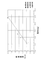
- FIG. 3 shows the cooling rated operation, the heating rated operation, the cooling intermediate operation (for example, the cooling operation performed under the condition that the outside air temperature is 18 ° C. to 20 ° C.), and the heating intermediate operation.
- 7 is a graph showing the relationship of the COP ratio to the front wind speed of the outdoor fan 28 (for example, during heating operation performed under conditions where the outside air temperature is 13 ° C. to 18 ° C.).
- the point shown in FIG. 4 is, for example, the front wind speed (cooling) of the outdoor fan 28 with a COP ratio of 100% during the cooling rated operation, the heating rated operation, the cooling intermediate operation, and the heating intermediate operation shown in FIG.
- the rated operation is 2.0 m / s
- the heating rated operation is 1.46 m / s
- the cooling intermediate operation is 1.32 m / s
- the heating intermediate operation is 1.32 m / s. , 0.90 m / s) is plotted with the load as a parameter.
- the first relational expression is obtained by obtaining the plotted points by the least square method.
- the 1st relational expression is guide
- control unit 9 stores a relational expression (map) (hereinafter referred to as a second relational expression (map)) indicating the relationship of the rotational speed (air flow rate) of the outdoor fan 28 corresponding to the optimum COP front wind speed. Yes.
- the operation of the air conditioner 1 mainly includes a state in which the refrigerant circuit 10 is in the cooling cycle (that is, the state of the cooling operation and the state indicated by the solid line in FIG. 1 of the four-way switching valve 22), and the refrigerant circuit. 10 is a heating cycle (that is, a heating operation state and a state indicated by a broken line in FIG. 1 of the four-way switching valve 22).
- the operation of the air conditioner 1 is performed by the control unit 9.
- the air flow rate of the outdoor fan is often controlled to be constant (for example, in order to perform a large amount of heat exchange between the refrigerant and the outside air in the outdoor heat exchanger).
- the outdoor fan is controlled so that the air flow is always maximized).
- the COP may be affected (for example, when the load of the indoor unit is small, the air flow rate of the outdoor fan is always the maximum). To be controlled).
- the front wind speed at which the COP is optimal is different in each of four conditions of the cooling rated operation, the heating rated operation, the cooling intermediate operation, and the heating intermediate operation of the air conditioner 1. ing.
- control to change the air flow rate of the outdoor fan according to the operating condition of the air conditioner rather than performing control to always keep the air flow rate of the outdoor fan constant. Therefore, in the present embodiment, the following control of the air conditioner 1 is performed so that the COP is almost optimal even under different conditions.
- the refrigerant circuit 10 is controlled to be in a cooling cycle state (the four-way switching valve 22 is in a solid line state shown in FIG. 1). That is, the discharge side of the compressor 21 is connected to the gas side of the outdoor heat exchanger 23, and the suction side of the compressor 21 is connected to the gas of the indoor heat exchanger 42 via the gas side shut-off valve 27 and the gas side refrigerant communication pipe 7. It is controlled so as to be connected to the side.
- the low-pressure gas refrigerant is first sucked into the compressor 21 and compressed to become a high-pressure refrigerant. Thereafter, the high-pressure gas refrigerant is sent to the outdoor heat exchanger 23 via the four-way switching valve 22.
- the high-pressure gas refrigerant is condensed by exchanging heat with the outside air supplied by the outdoor fan 28 in the outdoor heat exchanger 23 to become a high-pressure liquid refrigerant.
- the high-pressure liquid refrigerant is decompressed by the outdoor expansion valve 24 to become a low-pressure gas-liquid two-phase refrigerant, and is sent to the indoor unit 4 via the liquid-side closing valve 26 and the liquid-side refrigerant communication pipe 6.
- the low-pressure gas-liquid two-phase refrigerant sent to the indoor unit 4 is sent to the indoor heat exchanger 41 where it is evaporated by exchanging heat with the indoor air in the indoor heat exchanger 41 to become a low-pressure gas refrigerant. .
- the low-pressure gas refrigerant is sent to the outdoor unit 2 via the gas-side refrigerant communication pipe 7 and the gas-side closing valve 27 and flows into the accumulator 25 via the four-way switching valve 22. Then, the low-pressure gas refrigerant that has flowed into the accumulator 25 is again sucked into the compressor 21.
- FIG. 5 is a flowchart showing the control of the outdoor fan 28 performed by the air conditioner 1 so as to optimize the COP.
- the load (deg) is calculated by subtracting the refrigerant condensing temperature in the outdoor heat exchanger 23 detected by the heat exchanger temperature sensor 33 from the outside air temperature detected by the outside air temperature sensor 34.
- step S2 the optimum COP front wind speed of the outdoor fan 28 is calculated from the load calculated in step S1 based on the first relational expression.
- step S3 the air flow rate of the outdoor fan 28 is controlled so that the front wind speed of the outdoor fan 28 becomes the optimum COP front wind speed calculated in step S2. That is, the control unit 9 determines the target rotational speed of the fan motor 28a from the optimum COP front wind speed using the second relational expression (map), and supplies the power of the frequency corresponding to the target rotational speed of the outdoor fan 28 to the inverter device. The amount of air blown by the outdoor fan 28 is controlled by inputting to the fan motor 28a.
- FIG. 1 Control at the time of heating operation of the air conditioner 1
- the refrigerant circuit 10 is controlled to be in a heating cycle state (the four-way switching valve 22 is in a broken line state shown in FIG. 1). That is, the discharge side of the compressor 21 is connected to the gas side of the indoor heat exchanger 42 via the gas side closing valve 27 and the gas side refrigerant communication pipe 7, and the suction side of the compressor 21 is the gas of the outdoor heat exchanger 23. It is controlled so as to be connected to the side.
- the low-pressure gas refrigerant is sucked into the compressor 21 and compressed to become a high-pressure gas refrigerant.
- This high-pressure gas refrigerant is sent to the indoor unit 4 via the four-way switching valve 22, the gas-side closing valve 27, and the gas-side refrigerant communication pipe 7.
- the high-pressure gas refrigerant sent to the indoor unit 4 is condensed by exchanging heat with the indoor air supplied by the indoor fan 43 in the indoor heat exchanger 42 to become high-pressure liquid refrigerant.
- the high-pressure liquid refrigerant is sent to the outdoor unit 2 via the liquid-side refrigerant communication pipe 6 and the liquid-side closing valve 26.
- the high-pressure liquid refrigerant sent to the outdoor unit 2 is reduced in pressure by the outdoor expansion valve 24 to become a low-pressure gas-liquid two-phase refrigerant and sent to the outdoor heat exchanger 23.
- the low-pressure gas-liquid two-phase liquid refrigerant evaporates by exchanging heat with the outside air supplied by the outdoor fan 28 in the outdoor heat exchanger 23 to become a low-pressure gas refrigerant.
- This low-pressure gas refrigerant flows into the accumulator 25 via the four-way switching valve 22 and is sucked into the compressor 21 again.
- the refrigerant circuit 10 enters an operation cycle in which the room temperature detected by the room temperature sensor 44 becomes a set temperature set by the user via the remote controller (that is, a stable operation state cycle), As in the cooling operation, the amount of air blown by the outdoor fan 28 is controlled, and the COP of the air conditioner 1 is generally optimal at all times.
- the control of the air flow rate of the outdoor fan 28 during the heating operation is substantially the same as the control of the air flow rate of the outdoor fan 28 during the cooling operation (see steps S1 to S3, see FIG. 5).
- the load is calculated by subtracting the evaporation temperature of the refrigerant in the outdoor heat exchanger 23 from the outside air temperature.
- the control unit 9 calculates the load using the difference between the refrigerant temperature and the outside air temperature in the outdoor heat exchanger 23, and obtains the load obtained using the first relational expression. Based on the above, control is performed to adjust the air flow rate of the outdoor fan 28 to the optimum COP front wind speed of the outdoor fan 28. Thereby, even if the outdoor temperature fluctuates depending on the installation conditions and the installation environment of the outdoor unit 2, the outdoor fan can be calculated more finely by calculating the load based on the difference between the outdoor temperature and the temperature of the heat source side heat exchanger 23. It is possible to control the air flow rate of 28. As a result, the COP of the air conditioner 1 can be generally optimized even under different operating conditions.
- Patent Document 1 Japanese Patent Laid-Open No. 10-30853
- an air conditioner has been proposed in which the air volume of an outdoor fan is controlled so that the COP is optimized based on the outside air temperature.
- the air flow of the outdoor fan is controlled to be small.
- the load for example, the load of the outdoor heat exchanger
- the load is high when the outdoor environment where the outdoor unit is installed is, for example, a typhoon or rain / snow, or when the outdoor unit has an outlet or an inlet.
- the outdoor unit has an outlet or an inlet.
- the present embodiment not only the outside air temperature but also the temperature of the refrigerant in the outdoor heat exchanger 23 (condensing temperature of the refrigerant flowing in the outdoor heat exchanger 23 during the cooling operation, outdoor heat exchange during the heating operation).
- the load is calculated in consideration of the evaporating temperature of the refrigerant flowing in the chamber 23 (specifically, the load is calculated by subtracting the temperature of the refrigerant in the outdoor heat exchanger 23 from the outside air temperature).
- the optimum COP front wind speed is calculated from the load using the first relational expression, and the air flow rate of the outdoor fan 28 is controlled so as to be the optimum COP front wind speed.
- the air flow rate of the outdoor fan 28 can be controlled more finely.
- the first relational expression corresponds to the air flow rate of the outdoor fan 28 under the four main conditions such as the cooling rated operation, the heating rated operation, the cooling intermediate operation, and the heating intermediate operation of the air conditioner 1.
- the optimum COP front wind speed of the outdoor fan 28 is calculated based on the graph of the COP ratio to be generated, and the optimum COP front wind speed of the outdoor fan 28 is created using the load as a parameter.
- FIG. 6 is a system diagram of the refrigerant circuit 10 according to the modification (A).
- the description is limited to the so-called pair-type air conditioner 1 in which one indoor unit 4 is connected to one outdoor unit 2, but the present invention is limited to this. is not.
- a so-called multi-type air conditioner 100 in which a plurality of indoor units 4, 5,..., N are connected to one outdoor unit 2 may be used.
- the indoor expansion valves 44, 54,... That can be adjusted so that the refrigerant according to the load of the indoor units 4, 5,. ..N4 is provided. Note that the numbers given to the various devices of the indoor unit 5 shown in FIG.
- control unit 9 stores the first relational expression, but the present invention is not limited to this, and instead of the first relational expression, the outdoor fan 28 corresponding to the load. It may be a relation map showing the relation of the optimum COP front wind speed (m / s).
- D In the said embodiment, although limited and demonstrated to the air conditioner 1, this invention is not limited to this. For example, a heat pump type water heater may be used.
- E In the above embodiment, the room temperature is detected by the room temperature sensor 44, but the present invention is not limited to this.
- a suction temperature sensor (not shown) that detects the temperature of the suction air sucked into the indoor unit 4 is provided in the indoor unit 4, and the suction temperature detected by the suction temperature sensor is It may be the room temperature.
- the second embodiment will be described.
- the component apparatus etc. similar to 1st Embodiment a same sign is attached
- the difference between the second embodiment and the first embodiment will be briefly described.
- the optimum COP front wind speed is calculated from the load based on the first relational expression, and the outdoor is set to be the optimum COP front wind speed.
- the air flow rate of the fan 28 is controlled (hereinafter, this control is referred to as optimum wind speed control).
- control other than the optimum wind speed control may be performed depending on the situation.
- the air flow rate of the outdoor fan 28 is controlled in accordance with the optimal COP front wind speed (if the optimal wind speed control is performed), the APF (Annual Performance Factor) is generally optimal. . That is, if COP is improved, APF is also improved. The same applies to the air conditioner 1 of the first embodiment.
- the front wind speed in the range is defined as the allowable front wind speed.
- the allowable front wind speed control is performed according to the situation, but also the air flow rate of the outdoor fan 28 is controlled based on the allowable front wind speed.
- allowable wind speed control the control of the air flow rate of the outdoor fan 28 based on the allowable front wind speed.
- FIG. 7 is a flowchart showing control of the outdoor fan 28 of the air conditioner 1 according to the second embodiment.
- FIG. 8 is a graph showing the range of the allowable front wind speed.
- step S101 the degree of deviation between the set temperature and the room temperature detected by the room temperature sensor 44 (that is, a value obtained by subtracting the room temperature from the set temperature, indicated as T in the drawing) It is determined whether or not it is equal to or greater than a first threshold value (shown as x1 in the drawing) stored in the control unit 9.
- a first threshold value shown as x1 in the drawing
- the process proceeds to step S103, and when the degree of divergence is less than the first threshold, the process proceeds to step S102.
- step S102 optimal wind speed control is performed as in the first embodiment.
- the degree of divergence between the set temperature and the room temperature is less than the first threshold value, it can be determined that the user's comfort is satisfied by air conditioning by the air conditioner 1, so that energy saving is enhanced, that is, generally.
- the outdoor fan 28 is controlled so that the optimum COP / APF can be obtained.
- step S103 is the degree of deviation between the set temperature and the room temperature equal to or greater than a second threshold value stored in the control unit 9 in advance (second threshold value> first threshold value, indicated as x2 in the drawing)? Determine whether or not. If the divergence is greater than or equal to the second threshold, the process proceeds to step S104. On the other hand, if the divergence is less than the second threshold, the process proceeds to step S105. In step S104, it is determined that the difference between the set temperature and the room temperature is large, and the outdoor fan 28 is controlled according to the load of the indoor unit 4, or the outdoor fan 28 is operated at the maximum air volume (maximum number of rotations). Control to do.
- step S105 first, the load is calculated using the difference between the refrigerant temperature and the outside air temperature in the outdoor heat exchanger 23. Then, using the graph of FIG. 8, the allowable front wind speed of the outdoor fan 28 is calculated from the load, and the output of the outdoor fan 28 is controlled based on the allowable front wind speed. It is assumed that the control unit 9 stores in advance a relational expression (map) indicating the relationship between the allowable front wind speed and the air volume (rotation speed) of the outdoor fan 28.
- map relational expression
- the control unit 9 stores in advance a divergence-APF map in which the divergence between the room temperature and the set temperature and the relationship with the APF are shown. Then, based on the divergence degree-APF map, the APF is determined from the divergence degree, and the graph of the allowable front wind speed that becomes the APF is a plurality of graphs (A to H in FIG. 8) of FIG. Select from (Graph).
- the permissible front wind speed is calculated from the load, and as described above, the output of the outdoor fan 28 is controlled to be the calculated permissible front wind speed.
- A is a graph of the allowable front wind speed that becomes an APF determined based on the degree of deviation between the set temperature and the room temperature.
- the allowable front wind speed at which the load is 6.0 (deg) in the graph of A is about 1.44 (m / s).
- the air flow rate of the outdoor fan 28 is controlled so that
- the APF is A, E> B, F> C, G> D, H.
- the graphs of A, E, B, F, C, G, D, and H in FIG. 8 are respectively in a state where the optimum front wind speed during the cooling rated operation is fixed, during the heating intermediate operation, during the cooling intermediate operation, ⁇ 0.2 (m / s), ⁇ 0.4 (m / s), ⁇ 0.6 (m / s), ⁇ 0.8 (m / s) for the optimal COP front wind speed during heating rated operation It is a graph of the allowable front wind speed when added.
- the graph can be represented by a relational expression.
- the control unit 9 calculates the difference between the room temperature and the set temperature, and performs control (optimum wind speed control) in which priority is given to optimum energy saving performance based on the difference. , Determine whether to perform control (allowable wind speed control) in consideration of user comfort while maintaining suitable energy savings, that is, control that increases the operating capacity of the air conditioner 1 over optimal wind speed control. Yes.
- optimal wind speed control an optimal COP / APF is generally obtained.
- allowable wind speed control it is not optimal, but the conventional fan air flow rate is controlled without considering the load.
- COP / APF can be obtained more improved than in the case of doing so.
- the optimum wind speed control is not uniformly performed as in the first embodiment in consideration of various situations that may occur. Specifically, as described above, certain conditions are set, and whether to perform optimal wind speed control or allowable wind speed control depending on whether or not the conditions are satisfied (that is, whether optimal energy saving is prioritized or suitable energy saving is performed). Whether to perform control in consideration of the user's comfort while maintaining it). That is, the outdoor fan 28 can be controlled according to the situation.
- the permissible wind speed control is performed to obtain a COP / APF that is improved compared to the conventional one, while the user You can also consider the comfort.
- step S101 when it is determined in step S101 that the deviation between the set temperature and the room temperature is less than the first threshold in the flowchart of FIG. 7, optimal wind speed control is performed in step S102. It is not limited. For example, in the case of determining NO in step S101, a determination process for determining whether or not the degree of deviation between the set temperature and the room temperature is less than a third threshold is provided, and optimal wind speed control is performed based on the determination result. It may be determined whether to perform the allowable wind speed control.
- the outdoor fan 28 is controlled to operate at the minimum air volume (minimum rotation speed), and if the divergence degree is not less than the third threshold value, the optimum wind speed control is performed. It may be a control pattern to be performed. Further, if the degree of divergence is less than the third threshold value, the outdoor fan 28 is controlled to operate at the minimum air volume (minimum number of rotations). If the degree of divergence is not less than the third threshold value, the control pattern for performing the allowable wind speed control is used. There may be. Even in this case, an improved COP / APF can be obtained as compared with the case where the air volume of the outdoor fan 28 is controlled to be constant without considering the load.
- whether to perform the optimum wind speed control or the allowable wind speed control is determined based on the degree of deviation between the set temperature and the room temperature, but is not limited thereto. For example, based on the frequency of the compressor 21, it may be determined whether to perform optimal wind speed control or allowable wind speed control. In this case, in step S101 and step S103 in the flowchart of FIG. 7, the degree of deviation between the set temperature to be determined and the room temperature is replaced with the frequency of the compressor 21. Then, the first threshold value and the second threshold value replace the fourth threshold value and the fifth threshold value (4th threshold value ⁇ the fifth threshold value) stored in the control unit 9 in advance.
- step S101 it is determined whether or not the frequency of the compressor 21 is higher than a fourth threshold value. If it is determined that the frequency of the compressor 21 is higher than the fourth threshold, it is determined that the load is high, and it is determined in step S103 whether the frequency of the compressor 21 is higher than the fifth threshold. ing. If it is determined that the frequency of the compressor 21 is not higher than the fourth threshold value, optimal wind speed control is performed in step S102 as described above. Moreover, when it determines with the frequency of the compressor 21 not being higher than a 5th threshold value in step S105, permissible wind speed control is performed similarly to the above. When it is determined that the frequency of the compressor 21 is higher than the fifth threshold value, the process of step S104 is performed as described above.
- the frequency-APF map showing the relationship between the frequency of the compressor 21 and the APF is stored in advance in the control unit 9 as a premise for performing the allowable wind speed control in step S105. Yes.
- the APF is determined from the frequency of the compressor 21 based on the frequency-APF map, and the graph of the allowable front wind speed that becomes the APF is selected from the graphs of FIG. 8 (A to H graphs). Has been decided. Then, based on the graph of the permissible front wind speed, the permissible front wind speed is determined from the load.
- the graph of the allowable front wind speed is only eight graphs A to H, but is not limited to this, and may be eight or more. In this case, it is possible to perform control with more variable APF.
- the present invention is useful because the outdoor fan can be controlled so that COP / APF is improved even when the use conditions are different.
- Air conditioner (refrigeration equipment) 9 Control unit (control means) 10 Refrigerant circuit 21 Compressor 23 Outdoor heat exchanger (heat source side heat exchanger) 24 Outdoor expansion valve (expansion mechanism) 28 Outdoor fan (fan) 33 Heat exchange temperature sensor (heat exchange temperature detection means) 34 Outside temperature sensor (outside temperature detection means) 42 Indoor heat exchanger (use side heat exchanger) 100 Air conditioner (refrigeration equipment)
Landscapes
- Engineering & Computer Science (AREA)
- General Engineering & Computer Science (AREA)
- Mechanical Engineering (AREA)
- Chemical & Material Sciences (AREA)
- Combustion & Propulsion (AREA)
- Physics & Mathematics (AREA)
- Human Computer Interaction (AREA)
- Thermal Sciences (AREA)
- Fluid Mechanics (AREA)
- Fuzzy Systems (AREA)
- Mathematical Physics (AREA)
- Signal Processing (AREA)
- Air Conditioning Control Device (AREA)
Abstract
Description
しかし、近年の省エネルギー対策等を考慮すると、その他の運転時(例えば、暖房運転時)においてもCOPを向上させる制御が行われることが好ましい。
そこで、本発明の課題は、使用条件が異なる場合であってもCOPが向上するように室外ファンを制御することができる冷凍装置を提供することにある。
ここで、例えば、冷凍装置は、空調機である。また、ここで、例えば、送風ファンの送風量とは、冷凍装置のCOPが好適化するような送風量である。
第1発明に係る冷凍装置では、負荷に対応する送風ファンの送風量に基づいて送風ファンの出力を制御することによって、冷凍装置の使用条件が異なる場合であっても、COPが向上するように送風ファンの送風量を制御することができる。
第2発明に係る冷凍装置では、外気の温度と熱源側熱交換器の温度との差に基づいて負荷を算出し、送風ファンの出力を制御している。これにより、例えば、外気の温度が変動しても、熱源側熱交換器の温度との差で送風ファンの出力を制御することで、より細やかに送風ファンの送風量の制御を行うことができる。
第3発明に係る冷凍装置では、例えば、外気の温度が変動しても、熱源側熱交換器の温度との差で送風ファンの出力を制御することで、より細やかに送風ファンの送風量の制御を行うことができる。
第4発明に係る冷凍装置では、まず、負荷を算出し、そして、負荷と送風ファンの送風量との関係式から、負荷に対応する送風ファンの送風量を算出することによって、負荷の情報を入力する手間を省きつつ、送風ファンの送風量を正確に算出することができる。
第5発明に係る冷凍装置では、冷房運転時、熱源側熱交換器において、熱源側熱交換器内を流れる冷媒と外気との間で熱交換が行われている。つまり、熱源側熱交換器は、冷媒の凝縮器として機能している。よって、外気温度および熱源側熱交換器の凝縮温度を検出することによって、適当な負荷を算出することができる。
第6発明に係る冷凍装置では、暖房運転時、熱源側熱交換器において、熱源側熱交換器内を流れる冷媒と外気との間で熱交換が行われている。つまり、熱源側熱交換器は、冷媒の蒸発器として機能している。よって、外気温度および熱源側熱交換器の蒸発温度を検出することによって、適当な負荷を算出することができる。
第7発明に係る冷凍装置では、例えば、状況に応じて複数の関係式から1つの関係式を選択し、当該選択した関係式を用いて、負荷に対応する送風ファンの送風量を算出できることによって、状況に応じた送風ファンの制御を行うことができる。
第2発明に係る冷凍装置では、外気の温度と熱源側熱交換器の温度との差に基づいて負荷を算出し、送風ファンの出力を制御している。これにより、例えば、外気の温度が変動しても、熱源側熱交換器の温度との差で送風ファンの出力を制御することで、より細やかに送風ファンの送風量の制御を行うことができる。
第3発明に係る冷凍装置では、例えば、外気の温度が変動しても、熱源側熱交換器の温度との差で送風ファンの出力を制御することで、より細やかに送風ファンの送風量の制御を行うことができる。
第5発明に係る冷凍装置では、冷房運転時、熱源側熱交換器において、熱源側熱交換器内を流れる冷媒と外気との間で熱交換が行われている。つまり、熱源側熱交換器は、冷媒の凝縮器として機能している。よって、外気温度および熱源側熱交換器の凝縮温度を検出することによって、熱源側熱交換器の適当な負荷を算出することができる。
第6発明に係る冷凍装置では、暖房運転時、熱源側熱交換器において、熱源側熱交換器内を流れる冷媒と外気との間で熱交換が行われている。つまり、熱源側熱交換器は、冷媒の蒸発器として機能している。よって、外気温度および熱源側熱交換器の蒸発温度を検出することによって、熱源側熱交換器の適当な負荷を算出することができる。
<第1実施形態>
<空調機1の構成>
図1は、空調機1の冷媒回路10の系統図である。
空調機1は、蒸気圧縮式の冷凍サイクル運転を行うことによって、建物の室内の冷暖房に使用される機器である。空調機1は、図1に示すように、主として、1台の熱源ユニットとしての室外ユニット2と、室外ユニット2に接続される1台の利用ユニットとしての室内ユニット4と、室外ユニット2と室内ユニット4とを接続する冷媒連絡配管としての液側冷媒連絡配管6およびガス側冷媒連絡配管7とを備えている。すなわち、空調機1の蒸気圧縮式の冷媒回路10は、室外ユニット2と、室内ユニット4と、液側冷媒連絡配管6およびガス側冷媒連絡配管7とが接続されることによって構成されている。
まず、室内ユニット4の構成について説明する。
室内ユニット4は、建物の室内の天井に埋め込みや吊り下げにより、または、室内の壁面に壁掛けにより設置されている。室内ユニット4は、液側冷媒連絡配管6およびガス側冷媒連絡配管7を介して室外ユニット2に接続されており、冷媒回路10の一部を構成している。
室内ユニット4は、主として、冷媒回路10の一部を構成する室内側冷媒回路10aを有している。この室内側冷媒回路10aは、主として、利用側熱交換器としての室内熱交換器42を有している。
室内熱交換器42は、伝熱管と多数のフィンとにより構成されたクロスフィン式のフィン・アンド・チューブ型熱交換器であり、冷房運転時には、冷媒の蒸発器として機能して室内空気を冷却し、暖房運転時には、冷媒の凝縮器として機能して室内空気を加熱する。
また、室内ユニット4の室内空気の吸入口側には、室内ユニット4内に流入する室内空気の温度(すなわち、室内温度)を検出する室内温度センサ44が設けられている。
<室外ユニット2の構成>
次に、室外ユニット2の構成について説明する。
室外ユニット2は、建物の室外に設置されており、液側冷媒連絡配管6およびガス側冷媒連絡配管7を介して室内ユニット4に接続されている。そして、室外ユニット2は、室内ユニット4との間で冷媒回路10を構成している。
圧縮機21は、運転容量を可変することが可能な圧縮機であり、圧縮機用モータ21a(図2を参照)によって駆動される容積式圧縮機である。
四路切換弁22は、冷媒の流れ方向を切り換えるための弁である、四路切換弁22は、冷房運転時には、室外熱交換器23を圧縮機21によって圧縮される冷媒の凝縮器として機能させ、かつ、室内熱交換器42を室外熱交換器23において凝縮される冷媒の蒸発器として機能させるために、圧縮機21の吐出側と室外熱交換器23のガス側とを接続するとともに圧縮機21の吸入側(具体的には、アキュムレータ25)とガス側冷媒連絡配管7とを接続する(図1の四路切換弁22の実線を参照)。また、四路切換弁22は、暖房運転時には、室内熱交換器42を圧縮機21によって圧縮される冷媒の蒸発器として機能させるために、圧縮機21の吐出側とガス側冷媒連絡配管7とを接続するとともに圧縮機21の吸入側と室外熱交換器23のガス側とを接続することが可能である(図1の四路切換弁22の破線を参照)。
室外膨張弁24は、室外側冷媒回路10b内を流れる冷媒の圧力や流量の調節を行うために、室外熱交換器23の液側に接続された電動膨張弁である。
室外ユニット2は、室外ユニット2内に室外空気を吸入して、室外熱交換器23において冷媒と熱交換させた後に、室外に排出するための送風ファンである室外ファン28を有している。室外ファン28は、室外熱交換器23に供給する外気の量を可変することが可能なファンであり、ファンモータ28aによって駆動されるプロペラファンである。ファンモータ28aは、インバータ装置(図示せず)を介して電力の供給を受けて駆動されるようになっており、周波数(すなわち、回転数)を可変することによって、室外ファン28の風量を可変することが可能になっている。
液側閉鎖弁26およびガス側閉鎖弁27は、外部の機器・配管(具体的には、液側冷媒連絡配管6およびガス側冷媒連絡配管7)との接続口に設けられた弁である。液側閉鎖弁26は、室外熱交換器23に接続されている。ガス側閉鎖弁27は、四路切換弁22に接続されている。
また、室外ユニット2には、センサ33、34が設けられている。具体的には、室外熱交換器23に、室外熱交換器23内を流れる冷媒の温度(すなわち、冷房運転時における凝縮温度、または、暖房運転時における蒸発温度に対応する冷媒温度)を検出する熱交温度検出手段としての熱交温度センサ33が設けられている。また、室外ユニット2の室外空気の吸入口側には、室外ユニット2内に流入する室外空気(外気)の温度(すなわち、外気温度)を検出する外気温度検出手段としての外気温度センサ34が設けられている。
液側冷媒連絡配管6およびガス側冷媒連絡配管7は、空調機1を建物内の設置場所に設置する際に、現地にて施工される冷媒配管であり、設置場所や室外ユニット2と室内ユニット4との組み合わせの設置条件に応じて種々の長さや管径を有する冷媒配管が使用される。
図2は、制御部9の制御ブロック図である。
制御部9は、図2に示すように、室内制御部9aと、室外制御部9bとを有している。室内制御部9aおよび室外制御部9bは、メモリやマイクロコンピュータから構成される。室内制御部9aは、室内ユニット4を構成する各種機器(具体的には、室内ファン43)の動作を制御する。室外制御部9bは、室外ユニット2を構成する各種機器(具体的には、圧縮機21や室外ファン28等)の動作を制御する。
室内制御部9aは、室内ユニット4を個別に操作するためのリモコン(図示せず)との間で制御信号の送受信を行うことが可能である。また、室内制御部9aおよび室外制御部9bは、互いに伝送線を介して制御信号の送受信を行うことができるようになっている。そして、室内制御部9aと室外制御部9bとから構成される制御部9は、センサ33、34、44の検出信号を受信することができるように、センサ33、34、44と接続されており、これらの検出信号に基づいて、室内ファン43および室外ファン28の回転数、圧縮機21の回転数、室外膨張弁24の開度の制御を行うことができるようになっている。
また、制御部9には、図4に示すように、負荷に対応する室外ファン28の最適COP前面風速(m/s)(空調機1のCOPがおおむね最適となるような室外ファン28の前面風速)の関係を示す関係式(以下、第1関係式という)が記憶されている。具体的には、第1関係式は、y(m/s)=ax(deg)+bで表される。前面風速とは、室外ファン28の送風量を室外熱交換器23の面積で除したものである。負荷は、外気温度センサ34により検出される外気温度と熱交温度センサ33により検出される室外熱交換器23における冷媒の温度(すなわち、冷房運転時においては、室外熱交換器23内を流れる冷媒の凝縮温度、暖房運転時においては、室外熱交換器23内を流れる冷媒の蒸発温度)との差に基づくものである。具体的には、負荷は、外気温度から、室外熱交換器23における冷媒の温度を減算して算出される。
なお、第1関係式は、前面風速を利用して導かれていることから、空調機の馬力(電力量)に影響されるものではない。
また、制御部9には、最適COP前面風速に対応する室外ファン28の回転数(送風量)の関係を示す関係式(マップ)(以下、第2関係式(マップ)という)が記憶されている。
空調機1の動作としては、主として、冷媒回路10が冷房サイクルとなっている状態(すなわち、冷房運転の状態であり、四路切換弁22の図1の実線で示される状態)と、冷媒回路10が暖房サイクルとなっている状態(すなわち、暖房運転の状態であり、四路切換弁22の図1の破線で示される状態)とがある。なお、空調機1の動作は、制御部9によって行われるものである。
ここで、通常の冷房運転時および暖房運転時においては、室外ファンの送風量は一定に制御されることが多い(例えば、室外熱交換器において冷媒と外気との熱交換を多く行わせるために室外ファンの送風量が常時最大となるように制御される等)。しかし、室外ファンの送風量が常に一定に制御されると、COPに影響を与える場合があることが想定される(例えば、室内ユニットの負荷が小さい場合などにおいて、室外ファンの送風量が常に最大に制御される等)。
しかし、省エネルギー対策に鑑み、空調機のCOPがより好適となることが望ましいと考えられる。
一方、例えば、図3に示すように、空調機1の冷房定格運転時、暖房定格運転時、冷房中間運転時、暖房中間運転時のそれぞれの4条件において、COPが最適になる前面風速は異なっている。
よって、室外ファンの送風量を常に一定に保つ制御が行われるよりも、空調機の運転条件によって室外ファンの送風量を変更する制御が行われることが望ましいと考えられる。
そこで、本実施形態においては、異なる条件下であってもCOPがおおむね最適となるように、以下のような空調機1の制御を行っている。
まず、冷房運転時における空調機1の制御について図1を用いて説明する。
冷房運転時は、冷媒回路10が冷房サイクルの状態(四路切換弁22が図1に示す実線の状態)となるように制御されている。すなわち、圧縮機21の吐出側が室外熱交換器23のガス側に接続され、かつ、圧縮機21の吸入側がガス側閉鎖弁27およびガス側冷媒連絡配管7を介して室内熱交換器42のガス側に接続された状態となるように制御されている。
そして、この状態で、圧縮機21、室外ファン28および室内ファン43が駆動されると、まず、低圧のガス冷媒は、圧縮機21に吸入され、そして圧縮されて高圧の冷媒となる。この後、この高圧のガス冷媒は、四路切換弁22を経由して室外熱交換器23に送られる。この高圧のガス冷媒は、室外熱交換器23において、室外ファン28によって供給される外気と熱交換を行って凝縮されて高圧の液冷媒となる。そして、高圧の液冷媒は、室外膨張弁24によって減圧されて低圧の気液二相状態の冷媒となり、液側閉鎖弁26および液側冷媒連絡配管6を経由して室内ユニット4に送られる。室内ユニット4に送られた低圧の気液二相状態の冷媒は、室内熱交換器41に送られ、室内熱交換器41で室内空気と熱交換を行って蒸発されて低圧のガス冷媒となる。この低圧のガス冷媒は、ガス側冷媒連絡配管7およびガス側閉鎖弁27を経由して室外ユニット2に送られ、四路切換弁22を経由してアキュムレータ25に流入する。そして、アキュムレータ25に流入した低圧のガス冷媒は、再び、圧縮機21に吸入される。
図5は、空調機1の、COPが最適となるように行われる室外ファン28の制御を示すフローチャートである。
ステップS1では、外気温度センサ34により検出される外気温度から熱交温度センサ33により検出される室外熱交換器23における冷媒の凝縮温度が減算されることによって負荷(deg)が算出される。
ステップS3では、室外ファン28の前面風速がステップS2で算出された最適COP前面風速となるように、室外ファン28の送風量が制御される。すなわち、制御部9は、第2関係式(マップ)を用いて最適COP前面風速からファンモータ28aの目標回転数を決定し、この室外ファン28の目標回転数に対応する周波数の電力をインバータ装置を介してファンモータ28aに入力することによって、室外ファン28の送風量を制御している。
次に、暖房運転時における空調機1の制御について図1を用いて説明する。
暖房運転時は、冷媒回路10が暖房サイクルの状態(四路切換弁22が図1に示す破線の状態)となるように制御されている。すなわち、圧縮機21の吐出側がガス側閉鎖弁27およびガス側冷媒連絡配管7を介して室内熱交換器42のガス側に接続され、かつ、圧縮機21の吸入側が室外熱交換器23のガス側に接続された状態となるように制御されている。
そして、この状態で、圧縮機21、室外ファン28および室内ファン43が駆動されると、低圧のガス冷媒は、圧縮機21に吸入され、そして圧縮されて高圧のガス冷媒となる。この高圧のガス冷媒は、四路切換弁22、ガス側閉鎖弁27およびガス側冷媒連絡配管7を経由して室内ユニット4に送られる。室内ユニット4に送られた高圧のガス冷媒は、室内熱交換器42において、室内ファン43によって供給される室内空気と熱交換を行って凝縮されて高圧の液冷媒となる。高圧の液冷媒は、液側冷媒連絡配管6および液側閉鎖弁26を経由して室外ユニット2に送られる。そして、室外ユニット2に送られた高圧の液冷媒は、室外膨張弁24で減圧されて低圧の気液二相状態の冷媒となり、室外熱交換器23に送られる。低圧の気液二相状態の液冷媒は、室外熱交換器23において、室外ファン28によって供給される外気と熱交換を行って蒸発して低圧のガス冷媒となる。この低圧のガス冷媒は、四路切換弁22を経由してアキュムレータ25に流入し、そして再び、圧縮機21に吸入される。
以上のように、空調機1では、制御部9は、室外熱交換器23における冷媒の温度と外気温度との差を用いて負荷を算出し、そして第1関係式を用いて得られる、負荷に基づいた室外ファン28の最適COP前面風速に室外ファン28の送風量を合わせる制御を行っている。
これにより、室外ユニット2の設置条件や設置環境により外気温度が変動しても、外気温度と熱源側熱交換器23の温度との差で負荷を算出することで、より極め細やかに、室外ファン28の送風量の制御を行うことが可能になっている。また、これにより、異なる運転条件下においても、空調機1のCOPをおおむね最適とすることができるようになっている。
従来、特許文献1(特開平10-30853号公報)のように、外気温度に基づいてCOPが好適化するように室外ファンの風量を制御している空調機が提案されている。この空調機では、外気温度が低い場合は室外ファンの送風量が少なくなるように制御されている。しかし、外気温度が低い場合であっても負荷(例えば、室外熱交換器の負荷)が高い場合が想定され、この場合は室外ファンの風量を上げることが望ましい。ここで、外気温度が低い場合であっても負荷が高い場合とは、室外ユニットが設置される屋外の環境が例えば、台風や雨雪の場合や、また、室外ユニットが吹出口や吸入口が壁等に塞がれるように屋外に設置され室外熱交換器において熱交換がされにくい場合などが挙げられる。
よって、外気温度および室外熱交換器23における冷媒の温度の2つの検出値を用いて負荷を算出することで、より極め細やかに室外ファン28の送風量を制御することができるようになっている。
また、上述したように、第1関係式は、空調機1の冷房定格運転時、暖房定格運転時、冷房中間運転時、暖房中間運転時といった主な4条件における室外ファン28の送風量に対応するCOP比のグラフを基に、室外ファン28の最適COP前面風速を算出し、この室外ファン28の最適COP前面風速を、負荷をパラメータとして作成したものである。
そして、以上のような制御を行うことで、空調機1のCOPがおおむね最適となるようにすることができる。
<第1実施形態に係る空調機1の変形例>
以上、本発明の実施形態について図面に基づいて説明したが、具体的な構成は、上記の実施形態に限られるものではなく、発明の要旨を逸脱しない範囲で変更可能である。
図6は、本変形例(A)に係る冷媒回路10の系統図である。
上記実施形態では、1台の室外ユニット2に対して1台の室内ユニット4が接続される、いわゆるペア式の空調機1に限定して記載しているが、本発明はこれに限られるものではない。
例えば、図6に示すように、1台の室外ユニット2に複数台の室内ユニット4、5、・・・、nが接続される、いわゆるマルチ式の空調機100であってもよい。
この場合、室内ユニット4、5、・・・、nには、それぞれ室内ユニット4、5、・・・、nの負荷に応じた冷媒が流れるように調節可能な室内膨張弁44、54、・・・n4が設けられる。なお、図6に示す室内ユニット5の各種機器に付した番号は、室内ユニット4の各種機器を示す40番台の符号を50番台の符号に代えたものである。
(B)
上記実施形態では、室外熱交換器23に設けられる熱交温度センサ33によって室外熱交換器23内を流れる冷媒の温度を検出すると説明したが、本発明はこれに限られるものではない。
例えば、室外熱交換器23に圧力センサを設ける場合、この圧力センサによって検出される冷媒圧力を冷媒の飽和温度に換算した値を冷媒の温度として使用してもよい。
上記実施形態では、制御部9には第1関係式が記憶されていると説明したが、本発明はこれに限られるものではなく、第1関係式に代えて、負荷に対応する室外ファン28の最適COP前面風速(m/s)の関係を示す関係マップであってもよい。
(D)
上記実施形態では、空調機1に限定して説明したが、本発明はこれに限られるものではない。例えば、ヒートポンプ式の給湯器であってもよい。
(E)
上記実施形態では、室内温度を室内温度センサ44によって検出しているが、これに限られるものではない。例えば、室内温度センサ44に代えて、室内ユニット4に吸い込まれる吸込空気の温度を検出する吸込温度センサ(図示せず)を室内ユニット4に設け、当該吸込温度センサによって検出される吸込温度を、室内温度としてもよい。
続いて、第2実施形態について説明する。なお、第1実施形態と同様の構成機器等については、同符号を付し、説明を省略する。
第2実施形態の第1実施形態と異なる点について簡単に説明すると、第1実施形態では、第1関係式に基づいて負荷から最適COP前面風速を算出し、最適COP前面風速となるように室外ファン28の送風量を制御している(以下、当該制御を最適風速制御という)が、第2実施形態では、状況に応じて、最適風速制御以外の制御を行う場合があるという点である。
ここで、最適COP前面風速に合わせて室外ファン28の送風量を制御すれば(最適風速制御を行えば)、APF(Annual Performance Factor:通年エネルギー消費効率)もおおむね最適になることがわかっている。すなわち、COPが向上すれば、APFも向上する。このことについては、第1実施形態の空調機1においても同様である。
以下、第2実施形態における空調機1の室外ファン28の制御について図7を用いて説明する。なお、第1実施形態と同様に、以下の制御は、制御部9が行うものとする。
図7は、第2実施形態に係る空調機1の室外ファン28の制御を示すフローチャートである。図8は、許容前面風速の範囲を示すグラフである。
なお、上述の判定を行う前提として、制御部9は、設定温度及び室内温度のデータを取得しているものとする。
ステップS102では、第1実施形態と同様に、最適風速制御を行う。
ここでは、設定温度と室内温度との乖離度が第1閾値未満であれば、空調機1による空調によってユーザの快適性を満たしていると判断できるので、省エネ性が高まるように、すなわち、おおむね最適なCOP/APFが得られるように、室外ファン28を制御している。
ステップS104では、設定温度と室内温度との乖離度が大きいと判断して、室外ファン28を室内ユニット4の負荷に応じて制御する、又は、室外ファン28を最大風量(最大回転数)で運転するように制御する。すなわち、ここでは、COP/APFを考慮した(省エネ性を考慮した)制御を行わずに、ユーザの快適性を優先した制御を行う。
ステップS105では、まず、室外熱交換器23における冷媒の温度と外気温度との差を用いて負荷を算出する。そして、図8のグラフを用いて、負荷から室外ファン28の許容前面風速を算出し、当該許容前面風速に基づいて室外ファン28の出力を制御する。なお、制御部9には、予め、許容前面風速と、室外ファン28の送風量(回転数)との関係を示す関係式(マップ)が記憶されているものとする。
具体的に、ステップS105の処理について説明すると、例えば、設定温度と室内温度との乖離度に基づいて決定されたAPFになる許容前面風速のグラフがAであるとする。このとき、負荷が6.0(deg)の場合は、Aのグラフにおいて負荷が6.0(deg)となる許容前面風速は約1.44(m/s)であるので、この許容前面風速になるように、室外ファン28の送風量を制御している。
以上のように、第2実施形態では、制御部9は、室内温度と設定温度との差を算出し、当該差に基づいておおむね最適な省エネ性を優先した制御(最適風速制御)を行うか、好適な省エネ性を維持しながらユーザの快適性を考慮した制御(許容風速制御)、すなわち、最適風速制御よりも空調機1の運転能力を上げる制御、を行うかを判定して決定している。
これにより、最適風速制御を行う場合は、おおむね最適なCOP/APFが得られ、許容風速制御を行う場合は、最適ではないが、従来の、負荷を考慮せずに室外ファンの送風量を制御する場合に比べるとより向上したCOP/APFを得ることができる。
第2実施形態では、種々に起こりうる状況を考慮し、第1実施形態のように一律に最適風速制御を行っていない。具体的には、上述の通り、ある条件を設け、当該条件を満たすか否かによって、最適風速制御を行うか許容風速制御を行うか(すなわち、最適な省エネを優先するか、好適な省エネを維持しながら、ユーザの快適性も考慮した制御を行うか)を決定している。すなわち、状況に応じて室外ファン28の制御を行うことができる。よって、ユーザの快適性が満たされていないと判断する場合に空調機1の運転能力を上げたい場合、許容風速制御を行うことで、従来に比べてより向上したCOP/APFを得つつ、ユーザの快適性をも考慮できる。
(A)
上記実施形態では、図7のフローチャートにおいて、ステップS101で設定温度と室内温度との乖離度が第1閾値未満であると判定した場合は、ステップS102で最適風速制御を行っているが、これに限られるものではない。例えば、ステップS101でNOと判定する場合にさらに設定温度と室内温度との乖離度が第3閾値未満であるか否かを判定する判定処理を設け、当該判定結果に基づいて、最適風速制御を行うか、許容風速制御を行うかを決定してもよい。具体的には、乖離度が第3閾値未満であれば、室外ファン28を最小風量(最小回転数)で運転するように制御し、乖離度が第3閾値未満でない場合に、最適風速制御を行う制御パターンであってもよい。また、乖離度が第3閾値未満であれば、室外ファン28を最小風量(最小回転数)で運転するように制御し、乖離度が第3閾値未満でない場合、許容風速制御を行う制御パターンであってもよい。
この場合であっても、負荷を考慮せず室外ファン28の風量を一定に制御する場合に比べてより向上したCOP/APFを得ることができる。
上記実施形態では、設定温度と室内温度との乖離度に基づいて、最適風速制御を行うか許容風速制御を行うかを決定しているが、これに限られるものではない。例えば、圧縮機21の周波数に基づいて、最適風速制御を行うか許容風速制御を行うかを決定してもよい。この場合、図7のフローチャートにおける、ステップS101,ステップS103において、判定対象となる設定温度と室内温度との乖離度が、圧縮機21の周波数に代えられる。そして、第1閾値、第2閾値が、予め制御部9に記憶される第4閾値、第5閾値(第4閾値<第5閾値とする)に代わる。
なお、圧縮機21の周波数が第4閾値よりも高くないと判定する場合は、上述と同様に、ステップS102において最適風速制御を行う。また、ステップS105において、圧縮機21の周波数が第5閾値よりも高くないと判定する場合は、上述と同様に、許容風速制御を行う。また、圧縮機21の周波数が第5閾値よりも高いと判定する場合は、上述と同様に、ステップS104の処理を行う。
この場合であっても、負荷を考慮せず室外ファン28の風量を一定に制御する場合に比べてより向上したCOP/APFを得ることができる。
また、上述と同様にして、設定温度と室内温度との乖離度及び圧縮機21の周波数に基づいて、最適風速制御を行うか許容風速制御を行うかを決定してもよい。この場合であっても、上述と同様の効果を奏する。
上記実施形態では、許容前面風速のグラフは、A~Hの8つのグラフのみであるが、これに限られず、8つ以上であってもよい。この場合、よりAPFをきめ細やかに可変した制御を行うことができる。
9 制御部(制御手段)
10 冷媒回路
21 圧縮機
23 室外熱交換器(熱源側熱交換器)
24 室外膨張弁(膨張機構)
28 室外ファン(送風ファン)
33 熱交温度センサ(熱交温度検出手段)
34 外気温度センサ(外気温度検出手段)
42 室内熱交換器(利用側熱交換器)
100 空調機(冷凍装置)
Claims (7)
- 圧縮機(21)と熱源側熱交換器(23)と膨張機構(24)と利用側熱交換器(42)とが接続されることによって構成され、冷房サイクルと暖房サイクルとに可逆運転可能な冷媒回路(10)と、
前記熱源側熱交換器(23)に対して外気を送る送風ファン(28)と、
前記熱源側熱交換器(23)を流れる冷媒と熱交換を行う前記外気の温度を検出する外気温度検出手段(34)と、
前記熱源側熱交換器(23)の温度を検出する熱交温度検出手段(33)と、
前記外気の温度と、前記熱源側熱交換器(23)の温度とを用いて負荷を算出し、前記負荷に対応する前記送風ファン(28)の送風量に基づいて前記送風ファン(28)の出力を制御する制御手段(9)と、
を備える冷凍装置(1,100)。 - 前記制御手段(9)は、前記外気の温度と前記熱源側熱交換器(23)の温度との差に基づいて前記負荷を算出する、
請求項1に記載の冷凍装置(1,100)。 - 前記制御手段(9)は、前記外気の温度および前記熱源側熱交換器(23)の温度の一方から他方を減算して前記負荷を算出する、
請求項1に記載の冷凍装置(1,100)。 - 前記制御手段(9)は、前記負荷と前記送風ファン(28)の送風量との関係式から、前記負荷に対応する前記送風ファン(28)の送風量を算出する、
請求項1~3のいずれかに記載の冷凍装置(1,100)。 - 前記熱交温度検出手段(33)は、前記冷媒回路(10)が前記冷房サイクルとなっている状態において前記熱源側熱交換器(23)の凝縮温度を検出する凝縮温度検出手段である、
請求項1~4のいずれかに記載の冷凍装置(1,100)。 - 前記熱交温度検出手段(33)は、前記冷媒回路(10)が前記暖房サイクルとなっている状態において前記熱源側熱交換器(23)の蒸発温度を検出する蒸発温度検出手段である、
請求項1~4のいずれかに記載の冷凍装置(1,100)。 - 前記関係式は、複数あり、
前記制御手段(9)は、設定温度と室内温度との乖離度及び/又は前記圧縮機(21)の周波数に基づいて、複数の関係式から1つの関係式を選択し、前記1つの関係式から、前記負荷に対応する前記送風ファン(28)の送風量を算出する、
請求項4に記載の冷凍装置(1,100)。
Priority Applications (3)
| Application Number | Priority Date | Filing Date | Title |
|---|---|---|---|
| CN201080026183.4A CN102460030B (zh) | 2009-06-12 | 2010-06-09 | 制冷装置 |
| EP10785956.3A EP2442043B1 (en) | 2009-06-12 | 2010-06-09 | Freezer device |
| AU2010259838A AU2010259838B2 (en) | 2009-06-12 | 2010-06-09 | Refrigeration apparatus |
Applications Claiming Priority (2)
| Application Number | Priority Date | Filing Date | Title |
|---|---|---|---|
| JP2009-141206 | 2009-06-12 | ||
| JP2009141206 | 2009-06-12 |
Publications (1)
| Publication Number | Publication Date |
|---|---|
| WO2010143424A1 true WO2010143424A1 (ja) | 2010-12-16 |
Family
ID=43308687
Family Applications (1)
| Application Number | Title | Priority Date | Filing Date |
|---|---|---|---|
| PCT/JP2010/003840 WO2010143424A1 (ja) | 2009-06-12 | 2010-06-09 | 冷凍装置 |
Country Status (5)
| Country | Link |
|---|---|
| EP (1) | EP2442043B1 (ja) |
| JP (1) | JP4840522B2 (ja) |
| CN (1) | CN102460030B (ja) |
| AU (1) | AU2010259838B2 (ja) |
| WO (1) | WO2010143424A1 (ja) |
Families Citing this family (10)
| Publication number | Priority date | Publication date | Assignee | Title |
|---|---|---|---|---|
| JP5703849B2 (ja) * | 2011-03-03 | 2015-04-22 | 三菱電機株式会社 | ヒートポンプ式給湯装置 |
| JP5858777B2 (ja) * | 2011-12-28 | 2016-02-10 | 三菱電機株式会社 | 空気調和装置 |
| JP2014009869A (ja) * | 2012-06-28 | 2014-01-20 | Denso Corp | ヒートポンプサイクル |
| CN102777995B (zh) * | 2012-09-03 | 2016-04-13 | 北京德能恒信科技有限公司 | 一种多级热管热泵复合系统 |
| WO2016009488A1 (ja) * | 2014-07-14 | 2016-01-21 | 三菱電機株式会社 | 空気調和装置 |
| WO2016009487A1 (ja) * | 2014-07-14 | 2016-01-21 | 三菱電機株式会社 | 空気調和装置 |
| JP6365649B2 (ja) * | 2016-12-12 | 2018-08-01 | ダイキン工業株式会社 | 空気調和システム |
| CN107084479B (zh) * | 2017-04-13 | 2020-02-04 | 青岛海尔空调器有限总公司 | 一种空调器制热运行控制方法 |
| CN110081568B (zh) * | 2019-05-22 | 2021-05-28 | 广东美的制冷设备有限公司 | 空调器及其空调控制方法、控制装置和可读存储介质 |
| CN113294897A (zh) * | 2021-06-25 | 2021-08-24 | 美的集团股份有限公司 | 空调器的转速控制方法、空调器和存储介质 |
Citations (6)
| Publication number | Priority date | Publication date | Assignee | Title |
|---|---|---|---|---|
| JPH06159857A (ja) * | 1992-11-19 | 1994-06-07 | Mitsubishi Heavy Ind Ltd | 空気調和機 |
| JPH0791717A (ja) * | 1993-09-24 | 1995-04-04 | Hitachi Ltd | 空気調和機 |
| JPH1030853A (ja) | 1996-07-17 | 1998-02-03 | N T T Facilities:Kk | 空気調和機の制御装置 |
| JPH10148378A (ja) * | 1996-11-20 | 1998-06-02 | Sanyo Electric Co Ltd | 空気調和機 |
| WO2009047906A1 (ja) * | 2007-10-10 | 2009-04-16 | Daikin Industries, Ltd. | 空気調和装置 |
| JP2009299914A (ja) * | 2008-06-10 | 2009-12-24 | Panasonic Corp | 多室空気調和機 |
Family Cites Families (4)
| Publication number | Priority date | Publication date | Assignee | Title |
|---|---|---|---|---|
| US5144812A (en) * | 1991-06-03 | 1992-09-08 | Carrier Corporation | Outdoor fan control for variable speed heat pump |
| JPH06281280A (ja) * | 1993-03-29 | 1994-10-07 | Toshiba Corp | 空気調和装置 |
| EP1496317B1 (en) * | 2002-03-29 | 2010-11-24 | Daikin Industries, Ltd. | Air conditioner |
| CN1566831A (zh) * | 2003-06-17 | 2005-01-19 | 乐金电子(天津)电器有限公司 | 空调器除湿时节约电力的运作方法 |
-
2010
- 2010-06-02 JP JP2010127001A patent/JP4840522B2/ja not_active Expired - Fee Related
- 2010-06-09 CN CN201080026183.4A patent/CN102460030B/zh not_active Expired - Fee Related
- 2010-06-09 EP EP10785956.3A patent/EP2442043B1/en not_active Not-in-force
- 2010-06-09 WO PCT/JP2010/003840 patent/WO2010143424A1/ja active Application Filing
- 2010-06-09 AU AU2010259838A patent/AU2010259838B2/en not_active Ceased
Patent Citations (6)
| Publication number | Priority date | Publication date | Assignee | Title |
|---|---|---|---|---|
| JPH06159857A (ja) * | 1992-11-19 | 1994-06-07 | Mitsubishi Heavy Ind Ltd | 空気調和機 |
| JPH0791717A (ja) * | 1993-09-24 | 1995-04-04 | Hitachi Ltd | 空気調和機 |
| JPH1030853A (ja) | 1996-07-17 | 1998-02-03 | N T T Facilities:Kk | 空気調和機の制御装置 |
| JPH10148378A (ja) * | 1996-11-20 | 1998-06-02 | Sanyo Electric Co Ltd | 空気調和機 |
| WO2009047906A1 (ja) * | 2007-10-10 | 2009-04-16 | Daikin Industries, Ltd. | 空気調和装置 |
| JP2009299914A (ja) * | 2008-06-10 | 2009-12-24 | Panasonic Corp | 多室空気調和機 |
Non-Patent Citations (1)
| Title |
|---|
| See also references of EP2442043A4 |
Also Published As
| Publication number | Publication date |
|---|---|
| AU2010259838A1 (en) | 2012-02-02 |
| EP2442043B1 (en) | 2017-10-18 |
| JP2011017526A (ja) | 2011-01-27 |
| JP4840522B2 (ja) | 2011-12-21 |
| AU2010259838B2 (en) | 2013-02-07 |
| CN102460030B (zh) | 2014-10-15 |
| EP2442043A1 (en) | 2012-04-18 |
| EP2442043A4 (en) | 2013-11-13 |
| CN102460030A (zh) | 2012-05-16 |
Similar Documents
| Publication | Publication Date | Title |
|---|---|---|
| JP4840522B2 (ja) | 冷凍装置 | |
| JP5056855B2 (ja) | 空気調和装置 | |
| KR101462745B1 (ko) | 공기 조화 장치의 운전 제어 장치 및 이를 구비한 공기 조화 장치 | |
| JP5213966B2 (ja) | 冷凍サイクル装置 | |
| JP4497234B2 (ja) | 空気調和装置 | |
| JP5831661B1 (ja) | 空調機 | |
| JP5182358B2 (ja) | 冷凍装置 | |
| WO2009157191A1 (ja) | 空気調和装置および空気調和装置の冷媒量判定方法 | |
| WO2018155056A1 (ja) | 空気調和装置 | |
| JP2007218532A (ja) | 空気調和装置 | |
| JP2005249384A (ja) | 冷凍サイクル装置 | |
| JP5505477B2 (ja) | 空気調和装置および空気調和装置の冷媒量判定方法 | |
| JP5910719B1 (ja) | 空気調和装置 | |
| JP2009243832A (ja) | 空気調和装置 | |
| JP2008275216A (ja) | 空気調和機 | |
| KR101151321B1 (ko) | 멀티형 공기조화기 및 그 운전방법 | |
| JP6115594B2 (ja) | 空調室内機 | |
| CN104864517A (zh) | 空气调节装置 | |
| WO2023105605A1 (ja) | 冷凍サイクル装置、および制御方法 | |
| JP2017122573A (ja) | 直膨コイルを使用した空気調和機 | |
| JP2016114298A (ja) | 空気調和装置 | |
| JP2022172975A (ja) | 空気調和装置 | |
| KR20090087568A (ko) | 멀티형 공기조화기의 제어방법 |
Legal Events
| Date | Code | Title | Description |
|---|---|---|---|
| WWE | Wipo information: entry into national phase |
Ref document number: 201080026183.4 Country of ref document: CN |
|
| 121 | Ep: the epo has been informed by wipo that ep was designated in this application |
Ref document number: 10785956 Country of ref document: EP Kind code of ref document: A1 |
|
| NENP | Non-entry into the national phase |
Ref country code: DE |
|
| WWE | Wipo information: entry into national phase |
Ref document number: 2010259838 Country of ref document: AU |
|
| REEP | Request for entry into the european phase |
Ref document number: 2010785956 Country of ref document: EP |
|
| WWE | Wipo information: entry into national phase |
Ref document number: 2010785956 Country of ref document: EP |
|
| ENP | Entry into the national phase |
Ref document number: 2010259838 Country of ref document: AU Date of ref document: 20100609 Kind code of ref document: A |