WO2010143393A1 - 補聴器、中継器、補聴システム、補聴方法、プログラム、及び集積回路 - Google Patents
補聴器、中継器、補聴システム、補聴方法、プログラム、及び集積回路 Download PDFInfo
- Publication number
- WO2010143393A1 WO2010143393A1 PCT/JP2010/003758 JP2010003758W WO2010143393A1 WO 2010143393 A1 WO2010143393 A1 WO 2010143393A1 JP 2010003758 W JP2010003758 W JP 2010003758W WO 2010143393 A1 WO2010143393 A1 WO 2010143393A1
- Authority
- WO
- WIPO (PCT)
- Prior art keywords
- sound
- transmission
- unit
- propagation
- hearing aid
- Prior art date
Links
Images


Classifications
-
- H—ELECTRICITY
- H04—ELECTRIC COMMUNICATION TECHNIQUE
- H04R—LOUDSPEAKERS, MICROPHONES, GRAMOPHONE PICK-UPS OR LIKE ACOUSTIC ELECTROMECHANICAL TRANSDUCERS; DEAF-AID SETS; PUBLIC ADDRESS SYSTEMS
- H04R25/00—Deaf-aid sets, i.e. electro-acoustic or electro-mechanical hearing aids; Electric tinnitus maskers providing an auditory perception
- H04R25/43—Electronic input selection or mixing based on input signal analysis, e.g. mixing or selection between microphone and telecoil or between microphones with different directivity characteristics
-
- H—ELECTRICITY
- H04—ELECTRIC COMMUNICATION TECHNIQUE
- H04B—TRANSMISSION
- H04B7/00—Radio transmission systems, i.e. using radiation field
- H04B7/14—Relay systems
- H04B7/15—Active relay systems
-
- H—ELECTRICITY
- H04—ELECTRIC COMMUNICATION TECHNIQUE
- H04R—LOUDSPEAKERS, MICROPHONES, GRAMOPHONE PICK-UPS OR LIKE ACOUSTIC ELECTROMECHANICAL TRANSDUCERS; DEAF-AID SETS; PUBLIC ADDRESS SYSTEMS
- H04R25/00—Deaf-aid sets, i.e. electro-acoustic or electro-mechanical hearing aids; Electric tinnitus maskers providing an auditory perception
- H04R25/55—Deaf-aid sets, i.e. electro-acoustic or electro-mechanical hearing aids; Electric tinnitus maskers providing an auditory perception using an external connection, either wireless or wired
- H04R25/554—Deaf-aid sets, i.e. electro-acoustic or electro-mechanical hearing aids; Electric tinnitus maskers providing an auditory perception using an external connection, either wireless or wired using a wireless connection, e.g. between microphone and amplifier or using Tcoils
Definitions
- the present invention relates to a hearing aid, a repeater, and a hearing aid system provided with a function of cooperation with audio / video equipment and the like.
- Patent Document 1 and Patent Document 2 disclose a public place guidance broadcast is taken as an example of AV equipment and the like, and a technique for wirelessly relaying audio to a hearing aid using analog FM radio waves and magnetic induction is used. And its mounting method.
- Patent Document 3 discloses a wireless relay transmission technique that combines a short distance digital wireless communication of the BlueTooth standard and a magnetic induction communication as a similar technique. If this technology is used, the audio signal of the AV device can be easily wirelessly transmitted to the hearing aid by connecting a Bluetooth adapter or the like to the AV device.
- Patent Document 1 and Patent Document 2 when there are a plurality of FM transmitters, the FM radio wave to be relayed and transmitted from the plurality of FM radio waves emitted from each of the plurality of FM transmitters is specified. There is a need to. Furthermore, an operation for selecting the specified FM radio wave by some method is essential. Similarly, in the technique disclosed in Patent Document 3, when there are a plurality of BlueTooth wireless adapters, a plurality of operations such as a mutual authentication operation and a selective connection operation are indispensable.
- the present invention solves the conventional problems, and by automatically selecting a connected audio / video device, it is possible to simplify a connection switching operation between devices and provide a highly convenient hearing aid system. Objective.
- Each of the hearing aids outputs the transmission sound that propagates through the air and transmits the transmission sound signal corresponding to the propagation sound from an external device that transmits to the first transmission path.
- the sound obtained from the audio signal is output to the user.
- a sound collection unit that collects any of the propagation sounds output from each of the plurality of external devices, and reception that receives the transmission audio signal transmitted from each of the plurality of external devices.
- a comparison unit that compares the propagation sound collected by the sound collection unit with each of the plurality of transmission audio signals received by the reception unit and selects a transmission audio signal corresponding to the propagation sound
- an audio output unit that outputs a sound obtained from the transmission audio signal selected by the comparison unit to a user.
- connection switching between a plurality of external devices and hearing aids can be automatically performed without any special operation.
- the comparison unit calculates a correlation value between the waveform of the propagation sound and a sound waveform obtained from each of the plurality of transmission sound signals, and the transmission sound signal in which the calculated correlation value exceeds a predetermined threshold value May be selected.
- the hearing aid compares the sound collection timing of the propagation sound collected by the sound collection unit with the reception timing of the transmission audio signal selected by the comparison unit at the reception unit, A delay amount calculation unit that calculates a delay time of the transmission sound signal with respect to the propagation sound, and a delay amount calculation unit that is calculated for the external device that outputs the transmission sound signal selected by the comparison unit.
- a transmission unit may be provided that transmits a control signal for delaying and outputting the propagation sound by a delay time via the first transmission path.
- each of the plurality of external devices may output the propagation sound and the transmission sound signal by superimposing device specifying information for specifying the external device.
- the said comparison part may select the said transmission audio
- the sound collection unit may collect a composite propagation sound including the propagation sound and a sound emitted around the user.
- voice output part mixes the said composite propagation sound picked up by the said sound collection part, and the sound obtained from the said transmission audio
- an amplifying unit that amplifies the sound mixed in the mixing unit and outputs the amplified sound to the user.
- the hearing aid may include a notification unit that notifies the user that the composite propagation sound and the sound obtained from the transmission sound signal are mixed by the mixing unit.
- the user of the hearing aid can grasp whether or not the transmission audio signal is amplified and output.
- Each of the repeaters according to an aspect of the present invention outputs the propagation sound that propagates in the air, and obtains the transmission sound signal corresponding to the propagation sound from the external device that transmits to the first transmission path.
- the transmitted audio signal is relayed to the hearing aid.
- a sound collection unit that collects any of the propagation sounds output from each of the plurality of external devices, and reception that receives the transmission audio signal output from each of the plurality of external devices.
- a comparison unit that compares the propagation sound collected by the sound collection unit with each of the plurality of transmission audio signals received by the reception unit and selects a transmission audio signal corresponding to the propagation sound
- a transmission unit that transmits the transmission audio signal selected by the comparison unit to the hearing aid via a second transmission path different from the first transmission path.
- the comparison unit calculates a correlation value between the waveform of the propagation sound and a sound waveform obtained from each of the plurality of transmission sound signals, and the transmission sound signal in which the calculated correlation value exceeds a predetermined threshold value May be selected.
- the repeater compares the sound collection timing of the propagation sound collected by the sound collection unit with the timing at which the transmission audio signal transmitted by the transmission unit is received by the hearing aid.
- a delay amount estimation unit that estimates a delay time of the transmission sound signal with respect to the propagation sound, and the delay amount estimation unit for the external device that outputs the transmission sound signal selected by the comparison unit.
- a transmission unit that transmits the control signal for delaying and outputting the propagation sound through the first transmission path.
- a hearing aid system includes an external device that is a sound output source and a hearing aid that outputs the sound to a user.
- the external device includes an output unit that outputs a propagation sound that propagates in the air, and a transmission unit that transmits a transmission sound signal corresponding to the propagation sound to the first transmission path.
- the hearing aid includes a sound collection unit that collects any one of the propagation sounds output from each of the plurality of external devices, and a reception unit that receives the transmission audio signal output from each of the plurality of external devices.
- a comparison unit that compares the propagation sound collected by the sound collection unit with each of the plurality of transmission audio signals received by the reception unit and selects a transmission audio signal corresponding to the propagation sound; And an audio output unit that outputs a sound obtained from the transmission audio signal selected by the comparison unit to a user.
- a hearing aid system includes an external device that is a sound output source, a hearing aid that outputs the sound to a user, and a repeater that relays the sound acquired from the external device to the hearing aid.
- the external device includes an output unit that outputs a propagation sound that propagates in the air, and a first transmission unit that transmits a transmission sound signal corresponding to the propagation sound to a first transmission path.
- the repeater receives a sound collection unit that collects any one of the propagation sounds output from each of the plurality of external devices, and a transmission audio signal output from each of the plurality of external devices.
- the hearing aid is obtained from the second reception unit that receives the transmission voice signal transmitted from the repeater through the second transmission path, and the transmission voice signal received by the second reception unit.
- a sound output unit for outputting the sound to the user.
- Each of the hearing aid methods outputs the propagation sound that propagates in the air, and acquires the transmission sound signal corresponding to the propagation sound from the external device that transmits to the first transmission path.
- the sound obtained from the transmitted audio signal is output to the user.
- a sound collection step for collecting any of the propagation sounds output from each of the plurality of external devices, and reception for receiving the transmission audio signal transmitted from each of the plurality of external devices.
- a comparison step of comparing the propagation sound collected in the sound collection step with each of the plurality of transmission sound signals received in the reception step and selecting a transmission sound signal corresponding to the propagation sound
- an audio output step of outputting a sound obtained from the transmission audio signal selected in the comparison step to a user.
- Each of the programs according to an aspect of the present invention outputs the transmission sound that propagates through the air and transmits the transmission sound signal corresponding to the propagation sound from an external device that transmits to the first transmission path.
- the hearing aid is caused to execute a process of outputting the sound obtained from the audio signal to the user.
- a sound collection step for collecting any of the propagation sounds output from each of the plurality of external devices, and reception for receiving the transmission audio signal transmitted from each of the plurality of external devices.
- a comparison step of comparing the propagation sound collected in the sound collection step with each of the plurality of transmission sound signals received in the reception step and selecting a transmission sound signal corresponding to the propagation sound
- an audio output step of outputting the transmission audio signal selected in the comparison step as a sound to the user.
- Each of the integrated circuits outputs the propagation sound that propagates in the air and acquires the transmission sound signal corresponding to the propagation sound from the external device that transmits to the first transmission path.
- the sound obtained from the transmitted audio signal is output to the user.
- a sound collection unit that collects any of the propagation sounds output from each of the plurality of external devices, and reception that receives the transmission audio signal transmitted from each of the plurality of external devices.
- a comparison unit that compares the propagation sound collected by the sound collection unit with each of the plurality of transmission audio signals received by the reception unit and selects a transmission audio signal corresponding to the propagation sound
- an audio output unit that outputs a sound obtained from the transmission audio signal selected by the comparison unit to a user.
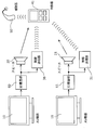
- FIG. 1 is a configuration diagram of a hearing aid system according to the first embodiment.
- FIG. 2 is a functional block diagram of the repeater in the first embodiment.
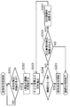
- FIG. 3 is a functional block diagram of the correlation detection unit in the second embodiment.
- FIG. 4 is a flowchart of the connection determination process in the first embodiment.
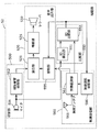
- FIG. 5 is a functional block diagram of the hearing aid in the first embodiment.
- FIG. 6 is a functional block diagram of a repeater in a modification of the first embodiment.
- FIG. 7 is an example of an external view of a repeater in a modification of the first embodiment.
- FIG. 8 is another example of an external view of a repeater in a modification of the first embodiment.
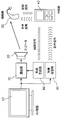
- FIG. 9 is a configuration diagram of a hearing aid system according to the second embodiment.
- FIG. 9 is a configuration diagram of a hearing aid system according to the second embodiment.
- FIG. 10 is a functional block diagram of the hearing aid in the second embodiment.
- FIG. 11 is a functional block diagram of a hearing aid in a modification of the second embodiment.
- FIG. 12 is a configuration diagram of a hearing aid system according to the third embodiment.
- FIG. 13 is a functional block diagram of the repeater in the third embodiment.
- FIG. 14 is a flowchart of connection determination processing according to the third embodiment.
- FIG. 15 is a configuration diagram of another hearing aid system according to the third embodiment.
- FIG. 16 is a functional block diagram of another hearing aid in the third embodiment.
- FIG. 17 is a configuration diagram of a hearing aid system according to the fourth embodiment.
- FIG. 18 is a functional block diagram of a hearing aid in the fourth embodiment.
- FIG. 19 is a functional block diagram of the repeater in the fourth embodiment.
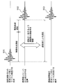
- FIG. 20 is a schematic diagram illustrating an outline of the delay adjustment processing.
- FIG. 21 is a configuration diagram of another hearing aid system according to the fourth embodiment.
- FIG. 22 is a functional block diagram of another hearing aid in the fourth embodiment.
- FIG. 23 is a configuration diagram of a hearing aid system according to the fifth embodiment.
- FIG. 24 is a functional block diagram of the repeater in the fifth embodiment.
- a hearing aid system includes an external device that is a sound output source, a hearing aid that outputs sound to a user, and a repeater that relays sound acquired from the external device to the hearing aid.
- the external device includes an output unit that outputs a propagation sound that propagates in the air, and a first transmission unit that transmits a transmission sound signal corresponding to the propagation sound to the first transmission path.
- the repeater is output from each of a plurality of external devices including the sound collection unit that collects one of the propagation sounds output from each of the plurality of external devices including the external device, and the external device.
- the first reception unit that receives the transmission sound signal, the propagation sound collected by the sound collection unit, and each of the plurality of transmission sound signals received by the first reception unit are compared to correspond to the propagation sound.
- a comparison unit that selects a transmission audio signal, and a second transmission unit that transmits the transmission audio signal selected by the comparison unit to the hearing aid via a second transmission path different from the first transmission path.
- the hearing aid has a second reception unit that receives a transmission audio signal transmitted from the repeater via the second transmission path, and a sound obtained from the transmission audio signal received by the second reception unit.
- an audio output unit that outputs to
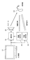
- the hearing aid system includes an AV device (sound / video device) 10 as a first external device, an AV device (sound / video device) 11 as a second external device, a repeater 40, and a hearing aid 50. Composed.
- the AV devices 10 and 11 include speakers 20 and 21 that are loudspeaker output units (output units) and radio transmitters 30 and 31 that are radio transmission units (transmission units), respectively.
- the speakers 20 and 21 output audio signals to be output from the AV devices 10 and 11 to the repeater 40 and the hearing aid 50 as propagation sounds propagating in the air, respectively.
- the wireless transmitters 30 and 31 transmit audio signals to be output by the AV devices 10 and 11 to the repeater 40 through the first transmission path as wireless transmission audio signals.
- the first transmission path is not particularly limited, for example, a wireless communication path such as a wireless LAN (Local Area Network) defined in IEEE 802.11 or Bluetooth is desirable.
- the first transmission path may be simply referred to as “wireless”.
- the radio transmission audio signal output from the radio transmitter 30 of the AV device 10 and the radio transmission audio signal output from the radio transmitter 31 of the AV device 11 have different transmission frequencies, for example.
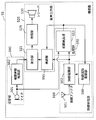
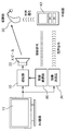
- the repeater 40 includes a microphone 400 that is a sound collection unit, a wireless reception unit 410 that is a reception unit that receives a wireless transmission audio signal transmitted wirelessly, a comparison unit 420, and a magnetic signal that is transmitted magnetically. And a magnetic transmission unit 450 that is a transmission unit that transmits to the hearing aid 50 via two transmission paths.
- the microphone 400 collects a propagation sound that propagates in the air. In addition to the propagation sound output from the speakers 20 and 21, the microphone 400 collects sound emitted around the user. That is, the microphone 400 actually collects a composite propagation sound including a propagation sound output from at least one of the speakers 20 and 21 and a sound emitted around the user.
- the propagation sound output from the speakers 20 and 21 is attenuated before reaching the microphone 400, the propagation sound output from the speakers 20 and 21 and the propagation sound collected by the microphone 400 are exactly the same. It may not be.
- the wireless reception unit 410 includes a wireless antenna 411, a wireless demodulation unit 412, and a wireless channel selection control unit 430.
- the wireless antenna 411 receives wireless transmission audio signals transmitted from the AV devices 10 and 11.
- the radio demodulation unit 412 demodulates the radio transmission audio signal received by the radio antenna 411 and outputs the audio signal obtained by the demodulation to the comparison unit 420 and the magnetic transmission unit 450.
- the radio channel selection control unit 430 causes the radio antenna 411 and the radio demodulation unit 412 to receive radio transmission audio signals in a specific frequency band by designating a frequency band to be received. That is, by switching the frequency band to be received by the radio channel selection control unit 430, the radio transmission audio signals output from the AV devices 10 and 11 can be received in order.
- the comparison unit 420 shown in FIG. 1 calculates the correlation value between the waveform of the propagation sound collected by the microphone 400 and the waveform of the sound signal (sound) obtained from each of the plurality of wireless transmission sound signals received by the wireless antenna 411.
- a correlation detection unit 423 that calculates and selects a radio transmission voice signal whose calculated correlation value exceeds a predetermined threshold among a plurality of radio transmission voice signals. Or the correlation detection part 423 may select the radio transmission audio
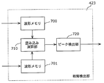
- the configuration of the correlation detection unit 423 will be described in more detail with reference to FIG. 3 includes waveform memories 700 and 701, a convolution operation unit 710, and a peak detection unit 720.
- the waveform memory 700 temporarily stores the waveform of the propagation sound for a predetermined time collected by the microphone 400.
- the waveform memory 701 temporarily stores the waveform of the audio signal for a predetermined time output from the wireless demodulation unit 412. It is desirable that the waveform memories 700 and 701 have a storage capacity capable of storing a signal waveform that is twice or more the delay time (described later) between the propagation sound and the wireless transmission sound signal.
- waveform memories 700 and 701 are not particularly limited.
- data such as DRAM (Dynamic random access memory), SRAM (Static random access memory), flash memory, or HDD (Hard Disc Drive) can be stored. Any storage medium can be employed.
- the convolution operation unit 710 performs a convolution operation on the waveform of the propagation sound stored in the waveform memory 700 and the waveform of the audio signal stored in the waveform memory 701 while shifting the time from each other.
- the peak detection unit 720 detects the presence or absence of a peak from the result of the convolution calculation performed by the convolution calculation unit 710. In addition, what is necessary is just to use the differential detection etc. conventionally known for the detection of a peak.
- the magnetic transmission unit 450 includes a magnetic antenna 451, a magnetic modulation unit 452, and a magnetic transmission control unit 440.
- the magnetic antenna 451 transmits the magnetically transmitted audio signal to the hearing aid 50 via the second transmission path.
- the magnetic modulation unit 452 modulates the audio signal demodulated by the radio demodulation unit 412 into a magnetic transmission audio signal and causes the magnetic antenna 451 to transmit it.
- the magnetic transmission control unit 440 controls the magnetic modulation unit 452 based on the detection result of the correlation detection unit 423.
- the microphone 400 collects a propagation sound that is a sound wave that has propagated through the air.
- the wireless receiving unit 410 receives a wirelessly transmitted audio signal transmitted wirelessly. Then, when the wireless transmission audio signal is received, the process of determining the connected AV devices 10 and 11 shown in FIG. 4 is started.
- the radio channel selection control unit 430 sends a control signal to the radio demodulation unit 412 so as to sequentially output the received radio transmission audio signal.
- the radio demodulation unit 412 demodulates the radio transmission audio signal according to this control signal, and outputs the audio signal obtained by the demodulation to the correlation detection unit 423 (step S102).
- the order of signals instructed by the radio channel selection control unit 430 to the radio reception unit 410 is the order of frequencies, such as from the lowest frequency band of the radio transmission audio signal to the higher frequency band.
- identification information that can distinguish each signal according to the signal transmission method, it may be instructed in order based on the identification information.
- the correlation detection unit 423 detects the correlation between the propagation sound collected by the microphone 400 and the audio signal received and demodulated by the wireless reception unit 410 (step S103). For this correlation, for example, a cross-correlation function of both time signal waveforms or power envelope waveforms is calculated, and when the peak value is equal to or greater than a predetermined threshold, it is determined that there is a significant correlation (step S104).
- This threshold value may be a fixed value determined experimentally, or may be variable depending on the collected propagation sound and the received wireless transmission voice signal.
- the correlation detection unit 423 that has detected and determined the correlation in this way outputs information on the determination result to the magnetic transmission control unit 440 when it is determined that there is a significant correlation (YES in step S104). Then, the magnetic transmission control unit 440 sends a control signal to the magnetic modulation unit 452 so as to perform magnetic transmission. Based on the control signal, the magnetic modulation unit 452 modulates the audio signal demodulated by the radio demodulation unit 412 into a magnetically transmitted audio signal and outputs the magnetic transmission audio signal to the magnetic antenna 451. Then, the magnetic antenna 451 transmits the magnetically transmitted audio signal modulated by the magnetic modulator 452 to the hearing aid 50 via the second transmission path. (Step S105).
- the correlation detection unit 423 determines whether there is a significant correlation (NO in step S104). If the correlation detection unit 423 does not determine that there is a significant correlation (NO in step S104), the correlation detection unit 423 outputs information on the determination result to the radio channel selection control unit 430.
- the radio channel selection control unit 430 that has acquired the determination result determines whether there is a next receivable frequency band (step S106). Then, when there is a receivable frequency band (YES in step S106), the radio channel selection control unit 430 sends a control signal to the radio antenna 411 and the radio demodulation unit 412 so as to receive the next radio transmission audio signal. send.
- the radio reception unit 410 receives the radio transmission audio signal to be determined next by the radio antenna 411, demodulates the received next radio transmission audio signal by the radio demodulation unit 412, and sends the demodulated audio signal to the correlation detection unit 423. Output (step S107).
- the radio channel selection control unit 430 determines that there is no frequency band that can be received next (NO in step S106), the relay process of determining the connection destination ends. In this way, the repeater 40 can determine any one of the AV devices 10 and 11 that are closest to the user of the hearing aid 50 as the connection destination.
- the process of determining the connection destination shown in FIG. 4 is repeatedly performed in units of a fixed time (for example, 500 msec).
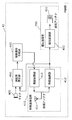
- the hearing aid 50 includes a sound collection unit 500, a magnetic reception unit 540 that is a reception unit, and an audio output unit 520.
- the sound collection unit 500 includes a microphone 501 and a hearing aid sound processing unit 502.
- the microphone 501 collects a propagation sound (or composite propagation sound) that propagates in the air.
- the hearing aid acoustic processing unit 502 performs acoustic processing on the propagation sound collected by the microphone 501.
- the magnetic receiver 540 includes a magnetic antenna 541 and a magnetic demodulator 543.
- the magnetic antenna 541 receives the magnetically transmitted audio signal from the repeater 40 via the second transmission path.
- the magnetic demodulator 543 demodulates the magnetic transmission audio signal received by the magnetic antenna 541 and acquires the audio signal.
- the audio output unit 520 includes a mixing unit 521, an amplification unit 525, and a receiver 530.
- the mixing unit 521 appropriately mixes the audio signal subjected to the acoustic processing by the hearing aid acoustic processing unit 502 and the audio signal received by the magnetic reception unit 540.
- the amplifying unit 525 amplifies the audio signal mixed by the mixing unit 521.
- the receiver 530 outputs the audio signal amplified by the amplifying unit 525 as a sound wave.
- the operation of the hearing aid 50 configured as described above will be described.
- the microphone 501 collects a propagation sound that is a sound wave that has propagated through the air.
- the hearing aid sound processing unit 502 performs hearing aid processing for improving the hearing of the user, such as noise removal processing and gain adjustment processing, for the propagation sound collected by the microphone 501.
- the magnetic antenna 541 of the magnetic receiver 540 receives the magnetically transmitted audio signal transmitted from the repeater 40 by magnetism.
- the magnetic demodulation unit 543 demodulates the magnetic transmission audio signal received by the magnetic antenna 541 and outputs the demodulated audio signal to the mixing unit 521.
- the mixing unit 521 When the audio signal demodulated from the magnetic reception unit 540 is not output, the mixing unit 521 outputs the audio signal acoustically processed by the hearing aid acoustic processing unit 502 to the amplification unit 525 as it is.
- the magnetic receiving unit 540 receives the magnetic transmission audio signal and outputs the demodulated audio signal
- the mixing unit 521 and the magnetic receiving unit 540 output the audio signal output from the hearing aid acoustic processing unit 502. Is mixed with the audio signal output from the signal output to the amplifier 525.
- This mixing process can be realized by performing weighted addition using a predetermined mixing ratio held by the mixing unit 521. For example, if the audio signal output from the magnetic receiving unit 540 and the audio signal output from the hearing aid acoustic processing unit 502 are mixed so that the output ratio is 8 to 2, the audio output from the magnetic receiving unit 540 The signal becomes dominant. By doing this, the influence of the audio signal that has propagated through the air and mixed with noise, etc. is reduced, and the influence of the audio signal that has been transmitted by radio and magnetic transmission is increased, so that the sound of the sound / video equipment that you want to hear The signal can be easily heard.
- the predetermined mixing ratio may be a constant value determined experimentally or may be changed based on an output signal from the magnetic receiver 540. For example, when the sound / video equipment that is the output source of the audio signal demodulated by the magnetic receiver 540 is frequently changed, the sound / video closest to the user is moved by the movement of the user of the hearing aid 50. The equipment is likely to change frequently. In such a case, it is highly likely that the user does not want to listen to the sound output from the sound / video equipment, so the mixing ratio is changed so that the output from the hearing aid acoustic processing unit 502 is dominant. May be.
- the user is close to the audio / video device. Most likely not moving. In such a case, there is a high possibility that the user wants to listen to the sound output from the audio / video device in a concentrated manner, so the mixing ratio is changed so that the output from the magnetic receiver 540 is more dominant. Also good. By setting it as such a mixing ratio, a more comfortable audio
- the amplification unit 525 amplifies the audio signal mixed by the mixing unit 521 according to the amplification degree set by the user with a switch or the like or according to the user's auditory information or the like.
- the receiver 530 outputs the amplified audio signal as a sound wave toward the user's external auditory canal.
- the two AV devices 10 and 11 are installed at spatially separated positions.
- the audio signal of the AV device 10 is amplified and output as a propagation sound in the air by the speaker 20 and is simultaneously transmitted as a radio transmission audio signal by the wireless transmitter 30.
- the audio signal of the AV device 11 is amplified and output as a propagation sound in the air by the speaker 21 and is simultaneously transmitted as a wireless transmission audio signal by the wireless transmitter 31.
- the AV devices 10 and 11 are in different rooms separated from each other by walls.
- a sound wave propagating in the air particularly a high-frequency sound wave, is easily blocked by a simple partition wall or the like. Therefore, as shown in FIG. 1, when a user who wears the hearing aid 50 and has the repeater 40 is in a room where the AV device 10 is located, the repeater 40 transmits the sound transmitted from the speaker 20 and wireless transmission.
- the radio transmission audio signal from the transmitter 30 and the radio transmission audio signal from the radio transmitter 31 are received.
- the repeater 40 is connected to the wireless transmitter 30 from the wireless transmitter 30. Is transmitted to the hearing aid 50 as a magnetically transmitted audio signal.
- the hearing aid 50 receives the audio signal of the AV device 10 from the wireless transmitter 30 via the repeater 40, the user wearing the hearing aid 50 receives the audio signal of the AV device 10 in the vicinity. You hear through the hearing aid 50.
- the sound propagated from the speaker 21 connected to the AV device 11 is dominant in the sound wave reaching the microphone 400 of the repeater 40.
- the meaning that the propagation sound from the speaker 21 is dominant means that the sound wave (decoded propagation sound) collected by the microphone 400 has more propagation sound output from the speaker 21 than the propagation sound output from the speaker 20. It means that it will be included.
- the magnetic transmission unit 450 stops the magnetic transmission.
- the connection destination determination process shown in FIG. 5 is repeated at regular intervals, when the propagation sound output from the speaker 21 becomes the main component in the propagation sound collected by the microphone 400, the wireless transmitter 31. Magnetic transmission of the radio transmission audio signal output from is started.
- the user who has moved can switch the output from the receiver 530 of the hearing aid 50 and listen to the audio signal of the AV device 11 that has come to be in the vicinity after the movement.
- a signal obtained by performing acoustic processing on the propagation sound collected by the microphone 501 is output from the receiver 530.
- this switching can be controlled so as not to give the user a great sense of incongruity such as nothing suddenly being output from the receiver 530.
- the state where the AV devices 10 and 11 are installed in different rooms has been described, of course, it is not limited to such a state.
- this hearing aid system makes it easy to hear the audio signals of the AV devices 10 and 11. be able to. That is, the audio signals of the AV devices 10 and 11 closest to the user wearing the hearing aid 50 should have the greatest influence on the sound waves collected by the microphone 400. For this reason, the propagation sound of the nearest AV devices 10 and 11 can be distinguished from the correlation between the collected propagation sound and the wireless transmission sound signal that is less influenced by the ambient sound and the like.
- appropriate sound processing is performed, and mixing and adjustment can be performed to output the desired voice from the receiver 530.
- a user who wears the hearing aid 50 and who has the repeater 40 approaches the AV devices 10 and 11 to be connected to perform special operations.
- the audio signals of the AV devices 10 and 11 can be easily heard.
- the sound output from the hearing aid 50 is switched to the sound signal of the AV device 11 without any special operation. Convenience for the user is improved.
- 1 describes the case where there are two audio / video devices.
- the number of audio / video devices is not limited to this, and can be applied to one or more arbitrary devices. Needless to say.
- the audio / video device is not switched, but the complicated connection operation is not necessary.
- the hearing aid user is near the audio / video device, the sound from the device is not changed. Can be easily heard.
- examples of the AV devices 10 and 11 include a television, a video device, a radio, a stereo device, a theater device, a personal computer, and a local broadcasting device.
- a signal line connecting the AV devices 10 and 11 and the wireless transmitters 30 and 31 an analog line signal, an optical digital signal, a coaxial digital signal, an HDMI compliant digital signal, or the like can be used.
- the speakers 20 and 21 and the wireless transmitters 30 and 31 may be incorporated in the housings of the AV devices 10 and 11. In such a case, the system can be installed more easily.
- wireless transmission and magnetic transmission are combined.
- a transmission method between devices is not limited to this, and wireless, magnetic, infrared, visible light, ultrasonic waves, and the like are used. Any combination can be used.
- the repeater 40 and the hearing aid 50 may be connected by wire.
- the correlation is obtained while sequentially switching the radio transmission audio signal.
- the correlation value is maximized after the correlation with all the radio transmission audio signals is detected once.
- a wireless transmission audio signal may be selected.
- processing such as selecting the radio transmission audio signal having the strongest signal strength according to the signal intensity of the radio transmission audio signal itself. It is also possible to add. In this way, the connection destination can be determined more reliably.
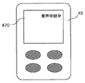
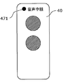
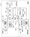
- the repeater 40 shown in FIG. 6 further includes a notification unit 460 in addition to the configuration of the repeater 40 shown in FIG.
- the notification unit 460 is for informing the user that the repeater 40 is relaying the transmission audio signal to the hearing aid 50. That is, the user of the hearing aid 50 uses the notification unit 460 to determine whether the sound currently heard from the hearing aid 50 is only the propagation sound collected by the microphone 501 or includes the transmission sound signal relayed by the repeater 40. Can be grasped.
- the specific configuration of the notification unit 460 is not particularly limited. However, the notification unit 460 may display “voice relaying” or the like on the display screen 470 as shown in FIG. 7, or as shown in FIG. An LED lamp 471 may be turned on (or blinked) to notify that the relay process is being executed.
- the hearing aid system according to Embodiment 2 includes an external device that is a sound output source and a hearing aid that outputs sound to the user.
- the external device includes an output unit that outputs a propagation sound that propagates in the air, and a transmission unit that transmits a transmission sound signal corresponding to the propagation sound to the first transmission path.
- the hearing aid has a sound collection unit that collects any of the propagation sounds output from each of the plurality of external devices including the external device, and a transmission output from each of the plurality of external devices including the external device.
- a comparison that selects a transmission sound signal corresponding to a propagation sound by comparing a reception unit that receives the sound signal, a propagation sound collected by the sound collection unit, and a plurality of transmission sound signals received by the reception unit. And an audio output unit that outputs a sound obtained from the transmission audio signal selected by the comparison unit to the user.
- the configuration of the hearing aid system according to Embodiment 2 of the present invention will be described with reference to FIG.
- the hearing aid system according to the second embodiment includes AV devices 10 and 11 and a hearing aid 51.
- the present hearing aid system is different from the first embodiment in that the hearing aid 51 and the AV devices 10 and 11 communicate directly without relaying by the repeater.
- the same components as those in the first embodiment are denoted by the same reference numerals, and description thereof is omitted.
- the configuration of the hearing aid 51 will be described with reference to FIG. 10 which is a functional block diagram of the hearing aid 51.
- the hearing aid 51 includes a sound collection unit 500, a wireless reception unit 560 that is a reception unit, a comparison unit 550, and an audio output unit 520. Similar to the hearing aid 50, the sound collection unit 500 includes a microphone 501 and a hearing aid sound processing unit 502.
- the radio reception unit 560 includes a radio antenna 561, a radio demodulation unit 562, and a radio channel selection control unit 590.
- the wireless antenna 561 receives the wireless transmission audio signal transmitted from the AV devices 10 and 11.
- Radio demodulation section 562 demodulates the radio transmission audio signal received by radio antenna 561, and outputs the audio signal obtained by demodulation to comparison section 550 and intermittent section 555.
- the radio channel selection control unit 590 causes the radio antenna 561 and the radio demodulation unit 562 to receive radio transmission audio signals in a specific frequency band by designating a frequency band to be received. That is, by switching the frequency band to be received by the wireless channel selection control unit 590, the wireless transmission audio signals output from the AV devices 10 and 11 can be received in order.
- the comparison unit 550 shown in FIG. 10 is similar to the comparison unit 420 in the repeater 40 of the first embodiment, based on the waveform of the propagation sound collected by the microphone 501 and the radio transmission audio signal received by the radio reception unit 560.
- a correlation detection unit 553 is provided that detects a correlation with the waveform of the obtained audio signal and selects a radio transmission audio signal whose calculated correlation value exceeds a predetermined threshold among a plurality of radio transmission audio signals. Or the correlation detection part 553 may select the radio transmission audio
- the specific configuration of the correlation detection unit 553 is the same as that of the correlation detection unit 423 shown in FIG.
- the audio output unit 520 further includes an intermittence unit 555 in addition to the mixing unit 521, the amplification unit 525, and the receiver 530.
- the intermittent unit 555 controls whether or not to output the audio signal acquired from the wireless reception unit 560 to the mixing unit 521.
- a typical example of the intermittent portion 555 is a switch.
- the two AV devices 10 and 11 are installed in spatially separated positions (for example, different rooms partitioned by walls), and the speakers 20 and 21 and the wireless transmitter 30, respectively. 31 is provided.
- the hearing aid 51 picks up the propagation sound from the speaker 20 with the microphone 501, and the wireless transmission audio signal from the wireless transmitter 30.
- the wireless antenna 561 receives the wireless transmission audio signal from the wireless transmitter 31.
- the wireless reception unit 560 of the hearing aid 51 When the wireless reception unit 560 of the hearing aid 51 receives the wireless transmission audio signal from the wireless transmitters 30 and 31, it enters a process of determining the audio / video device that is the connection destination.
- the radio channel selection control unit 590 sends a control signal to the radio demodulation unit 562 so as to output the received radio transmission audio signals in the order described in the first embodiment.
- the radio demodulation unit 562 demodulates the radio transmission audio signal and outputs the audio signal obtained by the demodulation to the correlation detection unit 553.
- the correlation detection unit 553 detects the correlation between the propagation sound collected by the microphone 501 and the audio signal demodulated by the wireless demodulation unit 562.
- the correlation detection and the correlation presence / absence determination may be performed in the same manner as in the first embodiment.
- This connection state refers to a state in which the audio signal demodulated by the wireless demodulation unit 562 is output to the mixing unit 521.
- the correlation detection unit 553 determines that there is a significant correlation, it outputs information of the determination result to the intermittent unit 555 and the radio channel selection control unit 590, and the intermittent unit 555 shifts to a disconnected state.
- This disconnected state refers to a state in which the audio signal demodulated by the wireless demodulation unit 562 is not output to the mixing unit 521.
- the radio channel selection control unit 590 demodulates the next radio transmission audio signal when the radio antenna 561 receives the next radio transmission audio signal, A control signal is sent to radio demodulation section 562 so as to output the demodulated audio signal.
- the radio demodulation unit 562 also demodulates the next radio transmission audio signal based on this control signal, and outputs the demodulated audio signal to the intermittent unit 555 and the correlation detection unit 553, almost as in the case of the repeater 40.
- the wireless channel selection control unit 590 ends the connection destination determination. In this case, since the determination information that there is a significant correlation is not sent from the correlation detection unit 553 to the interrupting unit 555, the disconnected state is set. Note that the presence / absence of a wireless transmission audio signal that can be received by the wireless antenna 561 and the determination of the connection destination are performed in units of a fixed time as in the first embodiment.
- the interrupting unit 555 controls whether or not to output the demodulated audio signal to the mixing unit 521. Then, the mixing unit 521 mixes and adjusts the propagation sound collected by the microphone 501 and the audio signal acquired from the wireless reception unit 560. This mixing and adjustment may be performed as described in the first embodiment.
- the audio of the AV device 10 in the vicinity of the user wearing the hearing aid 51 is heard by the user by wireless transmission.
- the sound wave that reaches the microphone 501 of the hearing aid 51 is predominantly output from the speaker 21 connected to the AV device 11.
- the correlation between the sound wave collected by the microphone 501 and the wireless transmission audio signal transmitted from the wireless transmitter 30 cannot be found.
- the interrupting portion 555 is once disconnected. If the sound from the speaker 21 is the main sound wave collected by the microphone 501 by the connection destination determination process described above, the sound included in the wireless transmission audio signal from the wireless transmitter 31 is received from the receiver 530. Is output.
- the user who has moved can switch the output from the receiver 530 of the hearing aid 51 and listen to the audio signal of the AV device 11 that has come to be in the vicinity after the movement. Further, at the time of this switching, the interrupting unit 555 is in a disconnected state, and an audio signal obtained by performing acoustic processing on the propagation sound received by the microphone 501 is output from the receiver 530.
- this switching can be controlled so as not to give the user a great sense of incongruity such as nothing being suddenly output from the receiver 530.
- the hearing aid system according to the second embodiment also has the same effect as the first embodiment even if the AV devices 10 and 11 are installed so as not to interrupt sound waves propagating in the air.
- the circuit scale and power consumption of the hearing aid 51 are larger than those of the hearing aid 50, but only by wearing the hearing aid 51 and approaching the AV devices 10 and 11, special operations are performed. It is possible to make it easy to hear the audio from the AV devices 10 and 11 without performing the above. In this hearing aid system, since a repeater is not required, the convenience for the user is further improved.
- the case where there are two audio / video devices has been described.
- the number of audio / video devices is not limited to this, and can be applied to one or more arbitrary devices. Not too long. Similar to the first embodiment, even if there is only one audio / video device, the connection operation is not necessary, and the convenience of the hearing aid user is improved.
- the AV devices 10 and 11 there are a television, a video device, a radio, a stereo device, a theater device, a personal computer, a local broadcasting device, and the like, as in the first embodiment.
- analog signal lines, optical digital signals, coaxial digital signals, HDMI-compliant digital signals, and the like can be used as signal lines for connecting the AV devices 10 and 11 and the wireless transmitters 30 and 31.
- the speakers 20 and 21 and the wireless transmitters 30 and 31 may be incorporated in the housings of the AV devices 10 and 11, and in this case, the system can be installed more easily.
- wireless transmission has been described as an example.
- the inter-device transmission method is not limited to this, and any wireless, magnetic, infrared, visible light, ultrasonic wave, or the like can be used. it can.
- the correlation is obtained while sequentially switching the radio transmission audio signal.
- the correlation value is maximized.
- a wireless transmission voice signal may be selected.
- processing such as selecting a radio transmission audio signal having a strong signal strength according to the signal intensity of the radio transmission audio signal itself is added. Is also possible. In this way, the connection destination can be determined more reliably.
- the sound collection unit collects the composite propagation sound including the propagation sound and the sound emitted around the user.
- the sound output unit includes a mixing unit that mixes the composite propagation sound collected by the sound collecting unit and the sound obtained from the transmission sound signal selected by the comparison unit at a predetermined mixing ratio, and a mixing unit. And an amplification unit that amplifies the mixed sound and outputs the amplified sound to the user.
- the hearing aid includes a notification unit that notifies the user that the composite propagation sound and the sound obtained from the transmission sound signal are mixed by the mixing unit.
- the hearing aid 51 shown in FIG. 11 further includes a notification sound generation unit 556 that is a notification unit in addition to the configuration of the hearing aid 51 shown in FIG.
- the notification sound generation unit 556 is for notifying the user that the audio signal output from the hearing aid acoustic processing unit 502 and the audio signal output from the wireless demodulation unit 562 are mixed by the mixing unit 521. . In other words, the user is notified that the interrupting section 555 is in a connected state.
- the notification sound generation unit 556 outputs a notification sound such as “starts output of the wireless transmission signal” to the mixing unit 521 at the timing when the interrupting unit 555 switches to the connected state. Then, the mixing unit 521 mixes the audio signal output from the hearing aid sound processing unit 502, the audio signal output from the radio demodulation unit 562, and the notification sound output from the notification sound generation unit 556, and amplifies the sound signal. To the unit 525. In addition, a notification sound such as “the output of the wireless transmission signal is finished” may be output to the mixing unit 521 at the timing when the interrupting unit 555 is switched to the disconnected state.
- the configuration of the hearing aid system according to Embodiment 3 of the present invention will be described with reference to FIG.
- the hearing aid system according to the third embodiment includes AV devices 10 and 11, a repeater 41, and a hearing aid 50.
- This hearing aid system is different from the first embodiment in that the ID superimposing units 60 and 61 are connected to the AV devices 10 and 11.
- the same components as those in the first embodiment are denoted by the same reference numerals, and description thereof is omitted.
- the ID superimposing units 60 and 61 are connected to the AV devices 10 and 11, respectively, and superimpose an ID signal that is a unique identification signal on the audio signals of the AV devices 10 and 11.
- the ID signal is a tone signal based on audible sound, a pilot signal based on non-audible sound, a watermark signal, and the like, and is more specifically a signal associated with the AV devices 10 and 11 to which the ID superimposing units 60 and 61 are connected. Is a signal for identifying the AV devices 10 and 11.
- the ID superimposing units 60 and 61 superimpose the ID signals associated with the AV devices 10 and 11 respectively on the audio signals output from the AV devices 10 and 11, respectively. In this way, the propagation sound in which the ID signal is superimposed in the air is amplified by the speakers 20 and 21, and at the same time, the audio signal on which the ID signal is superimposed is modulated by the radio transmitters 30 and 31 into the radio transmission audio signal and transmitted. .
- FIG. 13 is a functional block diagram of the repeater 41.
- the repeater 41 shown in FIG. 13 differs from the repeater 41 shown in FIG. 2 in the configuration of the comparison unit 420.
- the comparison unit 420 illustrated in FIG. 13 includes an ID detection unit 421 that detects an ID signal superimposed on the propagation sound picked up by the microphone 400, an ID signal superimposed on the propagation sound, and the wireless transmission sound.
- An ID comparison unit 422 that is a comparison unit that compares the ID signal superimposed on the signal. That is, the comparison unit 420 of the repeater 41 is different from the comparison unit 420 of the repeater 40 according to the first embodiment in that the comparison unit 420 includes the ID detection unit 421 and the ID comparison unit 422 and does not include the correlation detection unit 423.
- the ID detection unit 421 is connected to the microphone 400 and extracts an ID signal from the propagation sound collected by the microphone 400.
- the ID comparison unit 422 compares the ID signal extracted by the ID detection unit 421 with the ID signal extracted from the audio signal demodulated by the radio demodulation unit 412 and determines whether or not they match.
- the repeater 41 transmits the sound propagated from the speaker 20 and the wireless transmitter 30.
- the radio transmission audio signal and the radio transmission audio signal from the radio transmitter 31 are received.
- the repeater 41 receives the radio transmission audio signal from the radio transmitters 30 and 31, the process enters a process of determining a connection destination for relay.
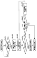
- connection destination determination process executed by the repeater 41 is partially different from the connection destination determination process (FIG. 4) executed by the repeater 40 according to Embodiment 1, and will be described with reference to FIG.
- the radio channel selection control unit 430 sends a control signal to the radio demodulation unit 412 so as to sequentially output the received radio transmission audio signal. send.
- the radio demodulation unit 412 demodulates the radio transmission audio signal according to the control signal, and extracts the ID signal from the audio signal obtained by demodulation. Then, the radio demodulation unit 412 outputs the audio signal to the magnetic modulation unit 452 and the ID signal to the ID comparison unit 422 (step S202).
- the ID detection unit 421 extracts an ID signal superimposed on the propagation sound collected by the microphone 400 (step S203).
- the ID signal demodulated by the radio demodulation unit 412 and the ID signal extracted by the ID detection unit 421 are input to the ID comparison unit 422 to determine whether or not they match (step S204).
- the ID comparison unit 422 When it is determined that the respective ID signals match (YES in step S204), the ID comparison unit 422 outputs information on the determination result to the magnetic transmission control unit 440, and the magnetic transmission control unit 440 performs magnetic transmission.
- a control signal is sent to the magnetic modulation unit 542.
- the magnetic modulation unit 452 Based on the control signal, the magnetic modulation unit 452 modulates the audio signal output from the radio demodulation unit 412 and outputs the magnetically transmitted audio signal obtained by the modulation to the magnetic antenna 451 (step S205).
- the ID comparison unit 422 determines that the ID signals do not match (NO in step S204)
- the ID comparison unit 422 outputs information on the determination result to the radio channel selection control unit 430.
- the radio channel selection control unit 430 that has acquired the determination result sends a control signal to the radio antenna 411 and the radio demodulation unit 412 so as to output an audio signal corresponding to the next radio transmission audio signal.
- the radio demodulation unit 412 of the radio reception unit 410 determines the audio signal and ID from the next radio transmission audio signal. The signal is demodulated, and the audio signal is output to the magnetic modulation unit 452 and the ID signal is output to the ID comparison unit 422 (step S207).
- connection destination determination process ends.
- the repeater 41 can also relay the audio signal of the AV device 10 in the vicinity to the hearing aid 50. Therefore, this hearing aid system can also make it easy to hear the audio signal of the AV device 10 in the vicinity of the user wearing the hearing aid 50, as in the hearing aid system of the first embodiment.
- the output from the receiver 530 can be switched.
- the ID comparison unit 422 detects a mismatch between the ID signal superimposed on the propagation sound and the ID signal superimposed on the wireless transmission audio signal.
- magnetic transmission is temporarily stopped, and a wireless transmission voice signal with a matching ID signal is newly selected by the connection destination determination process shown in FIG.
- the hearing aid 50 may perform the hearing aid process so as not to give the user a sense of discomfort.
- this hearing aid system can more reliably detect the association between the propagation sound and the wireless transmission voice signal by the ID signal, and is less prone to malfunction.
- the AV devices 10 and 11 include a television, a video device, a radio, a stereo device, a theater device, a personal computer, a private broadcasting device, and the like.
- analog line signals, optical digital signals, coaxial digital signals, HDMI-compliant digital signals, and the like can be used as the form of signal lines connecting the AV devices 10 and 11 to the wireless transmitters 30 and 31 and the ID superimposing units 60 and 61.
- the speakers 20 and 21 and the wireless transmitters 30 and 31 and the ID superimposing units 60 and 61 may be incorporated in the housings of the AV devices 10 and 11. In such a case, the system can be installed more easily.
- wirelessly transmitted ID signals are superimposed on the modulated wireless transmission audio signal itself, they are encoded and multiplexed as auxiliary information different from the wireless transmission audio signal. Also good.
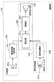
- the hearing aid 52 includes a sound collection unit 500, an audio output unit 520, a wireless reception unit 560 that is a reception unit, and a comparison unit 550 that includes an ID detection unit 551 and an ID comparison unit 552. And have.
- the ID detection unit 551 extracts an ID signal from the propagation sound collected by the microphone 501.
- the radio demodulation unit 562 demodulates the radio transmission audio signal and extracts an ID signal from the demodulated audio signal.
- the ID comparison unit 552 compares the ID signal extracted by the ID detection unit 551 with the ID signal extracted by the radio demodulation unit 562, and determines whether or not they match. The operation of each component is the same as described in the second and third embodiments.
- the circuit scale and power consumption of the hearing aid 52 are larger than those of the hearing aid 50, the convenience of the user is further improved because no repeater is required.
- the hearing aid according to the fourth embodiment further compares the sound collection timing of the propagation sound collected by the sound collection unit with the reception timing of the transmission sound signal selected by the comparison unit at the reception unit, A delay amount calculation unit that calculates a delay time with respect to the propagation sound of the transmission sound signal and an external device that outputs the transmission sound signal selected by the comparison unit, the propagation sound for the delay time calculated by the delay amount calculation unit.
- a transmission unit configured to transmit a control signal for delaying output via the first transmission path.
- the configuration of the hearing aid system according to Embodiment 4 of the present invention will be described with reference to FIG.
- the hearing aid system according to the fourth embodiment includes an AV device 10, a repeater 42, and a hearing aid 53.
- a delay device 70 and a wireless receiver 80 are connected to the AV device 10.
- the delay unit 70 is connected to the speaker 20 and a radio receiver 80 that receives a control signal for determining the delay amount of the delay unit 70.
- the same components as those described in Embodiments 1 to 3 are denoted by the same reference numerals, and description thereof is omitted.
- the hearing aid 53 includes a sound collection unit 500 including a microphone 501 and a hearing aid acoustic processing unit 502, and a sound output unit 520 including a mixing unit 521, an amplification unit 525, and a receiver 530. .
- the hearing aid 53 further includes a magnetic transmission / reception unit 545, a delay amount determination unit 580, and a control signal generation unit 585.
- the magnetic transmission / reception unit 545 modulates the control signal generated by the magnetic antenna 541 and the control signal generation unit 585 into a magnetic transmission control signal and transmits the modulated signal to the magnetic antenna 541 and received by the magnetic antenna 541.
- a magnetic demodulator 543 that demodulates the magnetically transmitted audio signal into an audio signal to be a mixing unit 521 and a delay amount determination unit 580;
- the delay amount determination unit 580 determines the time delay amount of the audio signal modulated by the magnetic demodulation unit 543 with respect to the propagation sound collected by the microphone 501.
- the control signal generation unit 585 generates a control signal corresponding to the delay amount determined by the delay amount determination unit 580 and outputs the control signal to the magnetic modulation unit 542.
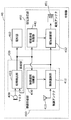
- the repeater 42 includes a wireless transmission / reception unit 415 and a magnetic transmission / reception unit 455.
- the radio transmission / reception unit 415 includes a radio antenna 411 that transmits / receives a radio transmission signal, a radio demodulation unit 412 that demodulates a radio transmission audio signal received by the radio antenna 411 into an audio signal, and outputs the audio signal to the magnetic modulation unit 452. Is modulated into a radio transmission control signal and transmitted to the radio antenna 411.
- the magnetic transmission / reception unit 455 includes a magnetic antenna 451 that transmits and receives a magnetic transmission signal, a magnetic modulation unit 452 that modulates the audio signal demodulated by the radio demodulation unit 412 into a magnetic transmission audio signal, and transmits the magnetic transmission signal to the magnetic antenna 451, and a magnetic antenna 451 includes a magnetic demodulation unit 453 that demodulates the received magnetic transmission control signal into a control signal and outputs the demodulated signal to the wireless modulation unit 413.
- the audio signal of the AV device 10 is loudly output as a propagation sound from the speaker 20 to the air via the delay unit 70.
- the initial value of the delay amount in the delay device 70 may be arbitrary, but may be, for example, zero delay, that is, no delay.
- Propagation sound as sound waves output from the speaker 20 is collected by the microphone 501 of the hearing aid 53, subjected to acoustic processing by the hearing aid acoustic processing unit 502, and then input to the mixing unit 521. This is also input to section 580.
- the radio transmission audio signal of the AV device 10 wirelessly transmitted from the radio transmitter 30 is received by the radio antenna 411 of the repeater 42, demodulated by the radio demodulation unit 412, and converted into a magnetic transmission audio signal by the magnetic modulation unit 452. Modulated and magnetically transmitted by the magnetic antenna 451.
- the repeater 42 includes the microphone 400, the comparison unit 420 including the correlation detection unit 423, the radio channel selection control unit 430, and the magnetic transmission control unit 440 in the same manner as the repeater 40. It may be configured to select a signal. Moreover, it is good also as having the comparison part 420 containing ID detection part 421 and ID comparison part 422 instead of the correlation detection part 423 like the repeater 41, and selecting the audio
- the magnetically transmitted audio signal magnetically transmitted from the repeater 42 is received by the magnetic antenna 541 of the hearing aid 53, demodulated by the magnetic demodulator 543, and the demodulated audio signal is output to the mixer 521 and at the same time the delay amount is determined. This is also input to section 580.
- the mixing unit 521, the amplification unit 525, and the receiver 530 perform the same operations as those described in Embodiments 1 to 3.
- the delay amount determination unit 580 and the control signal generation unit 585 will be specifically described.
- a time delay occurs in transmission. That is, as shown in FIG. 20, there is a time difference between the audio signal 901 reaching the user's ear and the microphone 501 and the audio signal 902 obtained by demodulating the transmission audio signal received via the repeater 42. Occurs.
- the delay amount determination unit 580 calculates this time difference, that is, the amount of transmission time delay, and outputs it to the control signal generation unit 585.
- This delay amount (also referred to as “delay time”) is, for example, a time for which a cross-correlation function of a time waveform between a sound signal 901 that is a propagation sound and a sound signal 902 obtained by demodulating a transmission sound signal is calculated, and a peak of a correlation value is given.
- the amount of deviation is calculated, for example. That is, the delay amount determination unit 580 has the same components as, for example, the correlation detection unit 423 shown in FIG. 3, and the amount of delay between the propagation sound and the transmission audio signal when a peak is detected is used as the delay amount. Output.
- the control signal generation unit 585 generates a control signal according to the information regarding the delay amount output from the delay amount determination unit 580, and outputs this control signal to the magnetic transmission / reception unit 545.
- the magnetic modulation unit 542 of the magnetic transmission / reception unit 545 modulates a control signal corresponding to the amount of transmission time delay into a magnetic transmission control signal.
- the magnetic antenna 541 magnetically transmits the modulated magnetic transmission control signal to the repeater 43.
- the magnetic transmission control signal transmitted magnetically is received by the magnetic transmission / reception unit 455 of the repeater 42.
- the magnetic transmission control signal received by the magnetic antenna 451 of the magnetic transmission / reception unit 455 is demodulated into a control signal by the magnetic demodulation unit 453, modulated into a wireless transmission control signal by the wireless modulation unit 413, and wirelessly transmitted from the wireless antenna 411 to the AV device 10. Sent.
- the control signal is received by the wireless receiver 80 of the AV device 10 through such a repeater 42.
- the control signal received and demodulated by the wireless receiver 80 is input to the delay unit 70.
- the delay unit 70 sets the same delay amount as the transmission time delay caused by the wireless transmission and the magnetic transmission based on the control signal.
- the delay device 70 delays the propagation sound that is output as a sound wave from the speaker 20 into the air based on the set delay amount.
- the propagation sound that propagates in the air and reaches the user's ear and the hearing aid 53 and the transmission sound signal that reaches the hearing aid 53 by radio and magnetic transmission are transmitted.
- the time difference can be reduced and the voice can be heard more easily.
- the hearing aid system has been described as having one audio / video device, but the present invention is not limited to this, and may be configured to include one or more audio / video devices. Even with a single audio / video device, a complicated connection operation is unnecessary, and the convenience of the hearing aid user is improved.
- the AV device 10 is a device such as a television as in the first to third embodiments.
- an analog line signal, an optical digital signal, a coaxial digital signal, an HDMI compliant digital signal, or the like can be used as a form of a signal line connecting the AV device 10 and the wireless transmitter 30 or the delay unit 70.
- the speaker 20, the wireless transmitter 30, and the delay device 70 may be incorporated in the housing of the AV device 10, and in such a case, the system can be installed more easily.
- wireless transmission and magnetic transmission are combined.
- a transmission method between devices is not limited to this, and wireless, magnetic, infrared, visible light, ultrasonic, Any combination of wired and the like can be used.
- the hearing aid system has been described as relaying by the repeater 42.
- the hearing aid 54 and the AV device 10 communicate directly without relaying by the repeater. It is good.
- the hearing aid 54 shown in FIG. 22, like the hearing aid 53, has a sound collection unit 500 including a microphone 501 and a hearing aid acoustic processing unit 502, and a sound including a mixing unit 521, an amplification unit 525, and a receiver 530.
- An output unit 520, a delay amount determination unit 580, and a control signal generation unit 585 are included.
- the hearing aid 54 includes a wireless transmission / reception unit 565 instead of the magnetic transmission / reception unit 545 of the hearing aid 53.
- the wireless transmission / reception unit 565 demodulates the wireless antenna 561, the wireless transmission audio signal received by the wireless antenna 561 into an audio signal, and outputs the audio signal to the mixing unit 521 and the delay amount determination unit 580, and the control signal A radio modulation unit 563 that modulates the radio transmission control signal and transmits the radio transmission control signal to the radio antenna 561.
- the wireless antenna 561 receives the wireless transmission audio signal wirelessly transmitted from the wireless transmitter 30, and the wireless demodulation unit 562 demodulates the wireless transmission audio signal received into the audio signal. . Further, the demodulated audio signal is output to the mixing unit 521 and simultaneously to the delay amount determination unit 580.
- the operations of the mixing unit 521, the amplification unit 525, and the receiver 530 are the same as those described in the first to third embodiments.
- the delay amount determination unit 580 and the control signal generation unit 585 of the hearing aid 54 operate in substantially the same manner as that of the hearing aid 53.
- the hearing aid 53 communicates with the AV device 10 via the repeater 42, while the hearing aid 54 communicates directly with the AV device 10.
- the hearing aid 54 may include a comparison unit 550 including a correlation detection unit 553, an intermittent unit 555, and a radio channel selection control unit 590, as in the hearing aid 51, or an ID detection unit as in the hearing aid 52.
- the comparison unit 550 including the 551 and the ID comparison unit 552 and the wireless channel selection control unit 590 may be included.
- the repeater according to the fifth embodiment further compares the sound collection timing of the propagation sound collected by the sound collection unit with the timing at which the transmission sound signal transmitted by the transmission unit is received by the hearing aid.
- a delay amount estimation unit that estimates a delay time for the propagation sound of the transmission sound signal, and an external device that outputs the transmission sound signal selected by the comparison unit, and the propagation sound for the delay time estimated by the delay amount estimation unit.
- a transmission unit that transmits a control signal for delaying and outputting the signal via the first transmission path.
- the configuration of the hearing aid system according to Embodiment 5 of the present invention will be described with reference to FIG.
- the hearing aid system according to the fifth embodiment includes an AV device 10, a repeater 43, and a hearing aid 50.
- the AV device 10 is connected to the speaker 20, the wireless transmitter 30, the delay device 70, and the wireless receiver 80.
- the hearing aid system according to the fourth embodiment is characterized in that the delay amount is determined by the repeater 43 so that the hearing aid system can be configured not by the hearing aid 53 for determining the delay amount but by the hearing aid 50 having no such function.
- the repeater 43 may include a comparison unit 420 including a correlation detection unit 423 or a comparison unit 420 including an ID detection unit 421 and an ID comparison unit 422, and further includes a radio channel selection control unit 430. Also good.
- the hearing aid 50 includes a correlation detection unit 553, an ID detection unit 551, an ID comparison unit 552, an intermittent unit 555, or a radio channel selection control unit 590. You may have.
- the same components as those described in Embodiments 1 to 4 are denoted by the same reference numerals, and description thereof is omitted.
- the delay amount estimation unit 490 receives the propagation sound collected by the microphone 400 and the audio signal demodulated by the radio demodulation unit 412 and estimates the delay amount of the audio signal transmitted wirelessly and magnetically.
- the control signal generation unit 495 generates a delay control signal from the output of the delay amount estimation unit 490.
- a time delay amount obtained by magnetic transmission between the repeater 43 and the hearing aid 50 is set in advance.
- the delay amount estimation unit 490 adds the set magnetic transmission delay amount to the time difference between the propagation sound from the microphone 400 and the sound signal from the radio demodulation unit 412, thereby directly reaching the user's ear. And the time difference (the amount of delay in transmission time) from the sound output from the hearing aid 50 via the repeater 43.
- the control signal generation unit 495 generates a control signal corresponding to the transmission time delay amount.
- the wireless transmission / reception unit 415 wirelessly transmits this control signal to the wireless receiver 80.
- the time difference between the sound waves that reach the user's ear and the sound that is output from the hearing aid 50 can be eliminated.
- the hearing aid system can use the hearing aid 50 having a low circuit scale and low power consumption, and thus can reduce the overall system cost.
- the hearing aid system has been described as having one audio / video device, but the present invention is not limited to this, and may be configured to include one or more audio / video devices. Even a single audio / video device does not require a complicated connection operation, which improves the convenience of the hearing aid user.
- the AV device 10 is a device such as a television set as exemplified in the first to fourth embodiments. Further, as the form of the signal line connecting the AV device 10 and the wireless transmitter 30 or the delay unit 70, an analog line signal or the like can be used as in the fourth embodiment.
- the speaker 20, the wireless transmitter 30, the delay device 70, and the wireless receiver 80 may be incorporated in the housing of the AV device 10, and in such a case, the system can be installed more easily. It can be carried out.
- wireless transmission and magnetic transmission are combined.
- a transmission method between devices is not limited to this, and wireless, magnetic, infrared, visible light, ultrasonic, wired, etc. Can be used in any combination.
- Each of the above devices is specifically a computer system including a microprocessor, a ROM, a RAM, a hard disk unit, a display unit, a keyboard, a mouse, and the like.
- a computer program is stored in the RAM or hard disk unit.
- Each device achieves its functions by the microprocessor operating according to the computer program.
- the computer program is configured by combining a plurality of instruction codes indicating instructions for the computer in order to achieve a predetermined function.
- a part or all of the components constituting each of the above devices may be configured by one system LSI (Large Scale Integration).
- the system LSI is a super multifunctional LSI manufactured by integrating a plurality of components on one chip, and specifically, a computer system including a microprocessor, a ROM, a RAM, and the like. .
- a computer program is stored in the RAM.
- the system LSI achieves its functions by the microprocessor operating according to the computer program.
- a part or all of the constituent elements constituting each of the above devices may be constituted by an IC card or a single module that can be attached to and detached from each device.
- the IC card or the module is a computer system including a microprocessor, a ROM, a RAM, and the like.
- the IC card or the module may include the super multifunctional LSI described above.
- the IC card or the module achieves its function by the microprocessor operating according to the computer program. This IC card or this module may have tamper resistance.
- the present invention may be the method described above. Further, the present invention may be a computer program that realizes these methods by a computer, or may be a digital signal composed of the computer program.
- the computer program or the digital signal may be recorded on a computer-readable recording medium.
- the computer-readable recording medium include a flexible disk, a hard disk, a CD-ROM, an MO, a DVD, a DVD-ROM, a DVD-RAM, a BD (Blu-ray Disc), and a semiconductor memory.
- the present invention may be the digital signal recorded on these recording media.
- the computer program or the digital signal may be transmitted via an electric communication line, a wireless or wired communication line, a network represented by the Internet, a data broadcast, or the like.
- the present invention may also be a computer system including a microprocessor and a memory.
- the memory may store the computer program, and the microprocessor may operate according to the computer program.
- the program or the digital signal is recorded on the recording medium and transferred, or the program or the digital signal is transferred via the network or the like, and executed by another independent computer system. It is good.
- the hearing aid system of the present invention can automatically switch the connection between a plurality of audio / video devices and the hearing aid without any special operation. Furthermore, the sound can be more easily heard by reducing the time difference between the sound wave that propagates in the air and reaches the user's ear and the microphone of the hearing aid and the sound signal that reaches the hearing aid by radio or magnetism. Thus, the present invention is extremely useful for realizing a highly functional hearing aid system.
Abstract
Description
本発明の他の形態に係る補聴システムは、音の出力元となる外部機器と、音を使用者に出力する補聴器と、外部機器から取得した音を補聴器に中継する中継器とを備える。外部機器は、空気中を伝播する伝播音を出力する出力部と、伝播音に対応する伝送音声信号を第1の伝送経路に送信する第1の送信部とを備える。中継器は、上記の外部機器を含む複数の外部機器それぞれから出力される伝播音のうちのいずれかを収音する収音部と、上記の外部機器を含む複数の外部機器それぞれから出力される伝送音声信号を受信する第1の受信部と、収音部で収音された伝播音と、第1の受信部で受信された複数の伝送音声信号それぞれとを比較し、伝播音に対応する伝送音声信号を選択する比較部と、比較部で選択された伝送音声信号を、第1の伝送経路と異なる第2の伝送経路を介して補聴器に送信する第2の送信部とを備える。補聴器は、中継器から第2の伝送経路を介して送信される伝送音声信号を受信する第2の受信部と、第2の受信部で受信された伝送音声信号から得られる音を、使用者に出力する音声出力部とを備える。
次に、図6~図8を参照して、実施の形態1の変形例に係る中継器40を説明する。なお、実施の形態1と同様の構成要素については同じ符号を用い、説明を省略する。
実施の形態2に係る補聴システムは、音の出力元となる外部機器と、音を使用者に出力する補聴器とを備える。外部機器は、空気中を伝播する伝播音を出力する出力部と、伝播音に対応する伝送音声信号を第1の伝送経路に送信する送信部とを備える。補聴器は、上記の外部機器を含む複数の外部機器それぞれから出力される伝播音のうちのいずれかを収音する収音部と、上記の外部機器を含む複数の外部機器それぞれから出力される伝送音声信号を受信する受信部と、収音部で収音された伝播音と、受信部で受信された複数の伝送音声信号それぞれとを比較し、伝播音に対応する伝送音声信号を選択する比較部と、比較部で選択された伝送音声信号から得られる音を、使用者に出力する音声出力部とを備える。
次に、図11を参照して、実施の形態2の変形例に係る補聴器51を説明する。なお、実施の形態2と同様の構成要素については同じ符号を用い、説明を省略する。実施の形態2の変形例に係る補聴器において、収音部は、伝播音と、使用者の周囲で発せられた音とを含む複合伝播音を収音する。そして、音声出力部は、収音部で収音された複合伝播音と、比較部で選択された伝送音声信号から得られる音とを、所定の混合比率で混合する混合部と、混合部で混合された音を、増幅して使用者に出力する増幅部とを備える。さらに、補聴器は、複合伝播音及び伝送音声信号から得られる音を混合部で混合したことを使用者に報知する報知部を備える。
図12を用いて、本発明の実施の形態3における補聴システムの構成について説明する。本実施の形態3の補聴システムは、AV機器10、11と、中継器41と、補聴器50とから構成される。本補聴システムは、AV機器10、11にID重畳部60、61が接続される点で実施の形態1と異なる。以下、実施の形態1と同様の構成要素については同じ符号を用い、説明を省略する。
実施の形態4に係る補聴器は、さらに、収音部で収音された伝播音の収音タイミングと、比較部で選択された伝送音声信号の受信部での受信タイミングとを比較することによって、伝送音声信号の伝播音に対する遅延時間を算出する遅延量算出部と、比較部で選択された伝送音声信号を出力する外部機器に対して、遅延量算出部で算出された遅延時間だけ伝播音を遅延させて出力させるための制御信号を、第1の伝送経路を介して送信する送信部とを備える。
実施の形態5に係る中継器は、さらに、収音部で収音された伝播音の収音タイミングと、送信部で送信された伝送音声信号が補聴器で受信されるタイミングとを比較することによって、伝送音声信号の伝播音に対する遅延時間を推定する遅延量推定部と、比較部で選択された伝送音声信号を出力する外部機器に対して、遅延量推定部で推定された遅延時間だけ伝播音を遅延させて出力させるための制御信号を、第1の伝送経路を介して送信する送信部とを備える。
なお、本発明を上記実施の形態に基づいて説明してきたが、本発明は、上記の実施の形態に限定されないのはもちろんである。以下のような場合も本発明に含まれる。
20,21 スピーカ
30,31 無線送信器
40,41,42,43 中継器
50,51,52,53,54 補聴器
60,61 ID重畳部
70 遅延器
80 無線受信器
400,501 マイク
410,560 無線受信部
411,561 無線アンテナ
412,562 無線復調部
413,563 無線変調部
415,565 無線送受信部
420,550 比較部
421,551 ID検出部
422,552 ID比較部
423,553 相関検出部
430,590 無線選局制御部
440 磁気送信制御部
450 磁気送信部
451,541 磁気アンテナ
452,542 磁気変調部
453,543 磁気復調部
455,545 磁気送受信部
460 報知部
470 表示画面
471 LEDランプ
490 遅延量推定部
495,585 制御信号生成部
500 収音部
502 補聴音響処理部
520 音声出力部
521 混合部
525 増幅部
530 レシーバ
540 磁気受信部
555 断続部
556 告知音生成部
580 遅延量判定部
700,701 波形メモリ
710 畳み込み演算部
720 ピーク検出部
901,902,903 音声信号
Claims (14)
- 各々が、空気中を伝播する伝播音を出力すると共に、前記伝播音に対応する伝送音声信号を第1の伝送経路に送信する外部機器から取得した前記伝送音声信号から得られる音を使用者に出力する補聴器であって、
複数の前記外部機器それぞれから出力される前記伝播音のうちのいずれかを収音する収音部と、
複数の前記外部機器それぞれから送信される前記伝送音声信号を受信する受信部と、
前記収音部で収音された前記伝播音と、前記受信部で受信された複数の前記伝送音声信号それぞれとを比較し、前記伝播音に対応する伝送音声信号を選択する比較部と、
前記比較部で選択された前記伝送音声信号から得られる音を使用者に出力する音声出力部とを備える
補聴器。 - 前記比較部は、前記伝播音の波形と、前記複数の伝送音声信号それぞれから得られる音の波形との相関値を算出し、算出した相関値が予め定めた閾値を上回る前記伝送音声信号を選択する
請求項1に記載の補聴器。 - 該補聴器は、さらに、
前記収音部で収音された前記伝播音の収音タイミングと、前記比較部で選択された前記伝送音声信号の前記受信部での受信タイミングとを比較することによって、前記伝送音声信号の前記伝播音に対する遅延時間を算出する遅延量算出部と、
前記比較部で選択された前記伝送音声信号を出力する前記外部機器に対して、前記遅延量算出部で算出された遅延時間だけ前記伝播音を遅延させて出力させるための制御信号を、前記第1の伝送経路を介して送信する送信部とを備える
請求項1又は2に記載の補聴器。 - 複数の前記外部機器それぞれは、前記伝播音及び前記伝送音声信号に当該外部機器を特定するための機器特定情報を重畳させて出力し、
前記比較部は、前記複数の前記伝送音声信号のうち、前記伝播音に重畳されている前記特定情報と同一の前記機器特定情報が重畳されている前記伝送音声信号を選択する
請求項1に記載の補聴器。 - 前記収音部は、前記伝播音と、使用者の周囲で発せられた音とを含む複合伝播音を収音し、
前記音声出力部は、
前記収音部で収音された前記複合伝播音と、前記比較部で選択された前記伝送音声信号から得られる音とを、所定の混合比率で混合する混合部と、
前記混合部で混合された音を、増幅して使用者に出力する増幅部とを備える
請求項1~4のいずれか1項に記載の補聴器。 - 該補聴器は、さらに、前記複合伝播音及び前記伝送音声信号から得られる音を前記混合部で混合したことを使用者に報知する報知部を備える
請求項5に記載の補聴器。 - 各々が、空気中を伝播する伝播音を出力すると共に、前記伝播音に対応する伝送音声信号を第1の伝送経路に送信する外部機器から取得した前記伝送音声信号を、補聴器に中継する中継器であって、
複数の前記外部機器それぞれから出力される前記伝播音のうちのいずれかを収音する収音部と、
複数の前記外部機器それぞれから出力される前記伝送音声信号を受信する受信部と、
前記収音部で収音された前記伝播音と、前記受信部で受信された複数の前記伝送音声信号それぞれとを比較し、前記伝播音に対応する伝送音声信号を選択する比較部と、
前記比較部で選択された前記伝送音声信号を、前記第1の伝送経路と異なる第2の伝送経路を介して前記補聴器に送信する送信部とを備える
中継器。 - 前記比較部は、前記伝播音の波形と、前記複数の伝送音声信号それぞれから得られる音の波形との相関値を算出し、算出した相関値が予め定めた閾値を上回る前記伝送音声信号を選択する
請求項7に記載の中継器。 - 該中継器は、さらに、
前記収音部で収音された前記伝播音の収音タイミングと、前記送信部で送信された前記伝送音声信号が前記補聴器で受信されるタイミングとを比較することによって、前記伝送音声信号の前記伝播音に対する遅延時間を推定する遅延量推定部と、
前記比較部で選択された前記伝送音声信号を出力する前記外部機器に対して、前記遅延量推定部で推定された遅延時間だけ前記伝播音を遅延させて出力させるための制御信号を、前記第1の伝送経路を介して送信する送信部とを備える
請求項7又は8に記載の中継器。 - 音の出力元となる外部機器と、前記音を使用者に出力する補聴器とを備える補聴システムであって、
前記外部機器は、
空気中を伝播する伝播音を出力する出力部と、
前記伝播音に対応する伝送音声信号を第1の伝送経路に送信する送信部とを備え、
前記補聴器は、
複数の前記外部機器それぞれから出力される前記伝播音のうちのいずれかを収音する収音部と、
複数の前記外部機器それぞれから出力される前記伝送音声信号を受信する受信部と、
前記収音部で収音された前記伝播音と、前記受信部で受信された複数の前記伝送音声信号それぞれとを比較し、前記伝播音に対応する伝送音声信号を選択する比較部と、
前記比較部で選択された前記伝送音声信号から得られる音を、使用者に出力する音声出力部とを備える
補聴システム。 - 音の出力元となる外部機器と、前記音を使用者に出力する補聴器と、前記外部機器から取得した音を前記補聴器に中継する中継器とを備える補聴システムであって、
前記外部機器は、
空気中を伝播する伝播音を出力する出力部と、
前記伝播音に対応する伝送音声信号を第1の伝送経路に送信する第1の送信部とを備え、
前記中継器は、
複数の前記外部機器それぞれから出力される前記伝播音のうちのいずれかを収音する収音部と、
複数の前記外部機器それぞれから出力される前記伝送音声信号を受信する第1の受信部と、
前記収音部で収音された前記伝播音と、前記第1の受信部で受信された複数の前記伝送音声信号それぞれとを比較し、前記伝播音に対応する伝送音声信号を選択する比較部と、
前記比較部で選択された前記伝送音声信号を、前記第1の伝送経路と異なる第2の伝送経路を介して前記補聴器に送信する第2の送信部とを備え、
前記補聴器は、
前記中継器から前記第2の伝送経路を介して送信される前記伝送音声信号を受信する第2の受信部と、
前記第2の受信部で受信された前記伝送音声信号から得られる音を、使用者に出力する音声出力部とを備える
補聴システム。 - 各々が、空気中を伝播する伝播音を出力すると共に、前記伝播音に対応する伝送音声信号を第1の伝送経路に送信する外部機器から取得した前記伝送音声信号から得られる音を、使用者に出力する補聴方法であって、
複数の前記外部機器それぞれから出力される前記伝播音のうちのいずれかを収音する収音ステップと、
複数の前記外部機器それぞれから送信される前記伝送音声信号を受信する受信ステップと、
前記収音ステップで収音された前記伝播音と、前記受信ステップで受信された複数の前記伝送音声信号それぞれとを比較し、前記伝播音に対応する伝送音声信号を選択する比較ステップと、
前記比較ステップで選択された前記伝送音声信号から得られる音を、使用者に出力する音声出力ステップとを含む
補聴方法。 - 各々が、空気中を伝播する伝播音を出力すると共に、前記伝播音に対応する伝送音声信号を第1の伝送経路に送信する外部機器から取得した前記伝送音声信号から得られる音を、使用者に出力する処理を補聴器に実行させるプログラムであって、
複数の前記外部機器それぞれから出力される前記伝播音のうちのいずれかを収音する収音ステップと、
複数の前記外部機器それぞれから送信される前記伝送音声信号を受信する受信ステップと、
前記収音ステップで収音された前記伝播音と、前記受信ステップで受信された複数の前記伝送音声信号それぞれとを比較し、前記伝播音に対応する伝送音声信号を選択する比較ステップと、
前記比較ステップで選択された前記伝送音声信号を、音として使用者に出力する音声出力ステップとを、補聴器に実行させる
プログラム。 - 各々が、空気中を伝播する伝播音を出力すると共に、前記伝播音に対応する伝送音声信号を第1の伝送経路に送信する外部機器から取得した前記伝送音声信号から得られる音を、使用者に出力する集積回路であって、
複数の前記外部機器それぞれから出力される前記伝播音のうちのいずれかを収音する収音部と、
複数の前記外部機器それぞれから送信される前記伝送音声信号を受信する受信部と、
前記収音部で収音された前記伝播音と、前記受信部で受信された複数の前記伝送音声信号それぞれとを比較し、前記伝播音に対応する伝送音声信号を選択する比較部と、
前記比較部で選択された前記伝送音声信号から得られる音を、使用者に出力する音声出力部とを備える
集積回路。
Priority Applications (4)
| Application Number | Priority Date | Filing Date | Title |
|---|---|---|---|
| US13/057,817 US8411887B2 (en) | 2009-06-08 | 2010-06-04 | Hearing aid, relay device, hearing-aid system, hearing-aid method, program, and integrated circuit |
| EP10785925.8A EP2442589A4 (en) | 2009-06-08 | 2010-06-04 | HEARING PROSTHESIS, RELAY DEVICE, HEARING AID SYSTEM, HEARING AID METHOD, PROGRAM, AND INTEGRATED CIRCUIT |
| JP2011518291A JP5383800B2 (ja) | 2009-06-08 | 2010-06-04 | 補聴器、中継器、補聴システム、補聴方法、プログラム、及び集積回路 |
| CN201080002232.0A CN102113350B (zh) | 2009-06-08 | 2010-06-04 | 助听器、中继器、助听系统、助听方法以及集成电路 |
Applications Claiming Priority (2)
| Application Number | Priority Date | Filing Date | Title |
|---|---|---|---|
| JP2009136965 | 2009-06-08 | ||
| JP2009-136965 | 2009-06-08 |
Publications (1)
| Publication Number | Publication Date |
|---|---|
| WO2010143393A1 true WO2010143393A1 (ja) | 2010-12-16 |
Family
ID=43308656
Family Applications (1)
| Application Number | Title | Priority Date | Filing Date |
|---|---|---|---|
| PCT/JP2010/003758 WO2010143393A1 (ja) | 2009-06-08 | 2010-06-04 | 補聴器、中継器、補聴システム、補聴方法、プログラム、及び集積回路 |
Country Status (6)
| Country | Link |
|---|---|
| US (1) | US8411887B2 (ja) |
| EP (1) | EP2442589A4 (ja) |
| JP (1) | JP5383800B2 (ja) |
| KR (1) | KR20120027100A (ja) |
| CN (1) | CN102113350B (ja) |
| WO (1) | WO2010143393A1 (ja) |
Cited By (6)
| Publication number | Priority date | Publication date | Assignee | Title |
|---|---|---|---|---|
| US20120300958A1 (en) * | 2011-05-23 | 2012-11-29 | Bjarne Klemmensen | Method of identifying a wireless communication channel in a sound system |
| US20120321112A1 (en) * | 2011-06-16 | 2012-12-20 | Apple Inc. | Selecting a digital stream based on an audio sample |
| JP2013153428A (ja) * | 2011-12-30 | 2013-08-08 | Gn Resound As | 音響信号の映像表示への同期性を向上させるシステム、補聴器、および方法 |
| EP2656637A2 (en) * | 2010-12-20 | 2013-10-30 | Phonak AG | Method for operating a hearing device and a hearing device |
| JP2014011710A (ja) * | 2012-07-02 | 2014-01-20 | Panasonic Corp | 携帯端末アダプタとそれを用いた補聴器システム |
| JP2016129330A (ja) * | 2014-12-29 | 2016-07-14 | ジーエヌ リザウンド エー/エスGn Resound A/S | 音源定位を備える聴音装置および関連する方法 |
Families Citing this family (22)
| Publication number | Priority date | Publication date | Assignee | Title |
|---|---|---|---|---|
| US9826320B2 (en) * | 2013-05-15 | 2017-11-21 | Gn Hearing A/S | Hearing device and a method for receiving wireless audio streaming |
| DE102013212853A1 (de) * | 2013-07-02 | 2015-01-08 | Siemens Medical Instruments Pte. Ltd. | Erkennen von Hörsituationen mit unterschiedlichen Signalquellen |
| EP2835986B1 (en) * | 2013-08-09 | 2017-10-11 | Oticon A/s | Hearing device with input transducer and wireless receiver |
| CN106797521B (zh) * | 2014-09-19 | 2020-03-17 | 科利耳有限公司 | 基于音频的控制信号表征来配置听力假体声音处理器 |
| US9641945B2 (en) | 2014-09-28 | 2017-05-02 | Ubdevice Corp. | Bluetooth hearing aid system |
| TWI654885B (zh) | 2015-06-23 | 2019-03-21 | 元鼎音訊股份有限公司 | 助聽器通訊系統及其助聽器通訊之方法 |
| GB201713697D0 (en) * | 2017-06-28 | 2017-10-11 | Cirrus Logic Int Semiconductor Ltd | Magnetic detection of replay attack |
| GB2563953A (en) | 2017-06-28 | 2019-01-02 | Cirrus Logic Int Semiconductor Ltd | Detection of replay attack |
| GB201801526D0 (en) | 2017-07-07 | 2018-03-14 | Cirrus Logic Int Semiconductor Ltd | Methods, apparatus and systems for authentication |
| GB201801532D0 (en) | 2017-07-07 | 2018-03-14 | Cirrus Logic Int Semiconductor Ltd | Methods, apparatus and systems for audio playback |
| GB201801527D0 (en) | 2017-07-07 | 2018-03-14 | Cirrus Logic Int Semiconductor Ltd | Method, apparatus and systems for biometric processes |
| GB201804843D0 (en) | 2017-11-14 | 2018-05-09 | Cirrus Logic Int Semiconductor Ltd | Detection of replay attack |
| GB201801664D0 (en) | 2017-10-13 | 2018-03-21 | Cirrus Logic Int Semiconductor Ltd | Detection of liveness |
| GB2567503A (en) | 2017-10-13 | 2019-04-17 | Cirrus Logic Int Semiconductor Ltd | Analysing speech signals |
| US11475899B2 (en) | 2018-01-23 | 2022-10-18 | Cirrus Logic, Inc. | Speaker identification |
| US11264037B2 (en) | 2018-01-23 | 2022-03-01 | Cirrus Logic, Inc. | Speaker identification |
| US11735189B2 (en) | 2018-01-23 | 2023-08-22 | Cirrus Logic, Inc. | Speaker identification |
| CN111357262A (zh) * | 2018-03-01 | 2020-06-30 | 索尼公司 | 真正无线蓝牙装置的动态嘴唇同步补偿 |
| US10692490B2 (en) | 2018-07-31 | 2020-06-23 | Cirrus Logic, Inc. | Detection of replay attack |
| US10915614B2 (en) | 2018-08-31 | 2021-02-09 | Cirrus Logic, Inc. | Biometric authentication |
| WO2022056126A1 (en) * | 2020-09-09 | 2022-03-17 | Sonos, Inc. | Wearable audio device within a distributed audio playback system |
| EP4344252A1 (en) | 2022-09-22 | 2024-03-27 | Sonova AG | System and method for providing hearing assistance |
Citations (8)
| Publication number | Priority date | Publication date | Assignee | Title |
|---|---|---|---|---|
| JPH09182192A (ja) * | 1995-12-22 | 1997-07-11 | Nec Corp | 受信機とともに用いる外部機器、補聴器及び補聴システム |
| JPH10285696A (ja) * | 1997-04-04 | 1998-10-23 | Gen Eng:Kk | 補聴装置 |
| JP2002238100A (ja) * | 2001-02-08 | 2002-08-23 | Maruzen Co Ltd | 難聴者支援方法およびその装置 |
| JP3431512B2 (ja) | 1998-09-04 | 2003-07-28 | リオン株式会社 | 音聴取装置 |
| JP3431511B2 (ja) | 1998-09-04 | 2003-07-28 | リオン株式会社 | 音聴取装置 |
| JP2006033853A (ja) * | 2004-07-21 | 2006-02-02 | Siemens Audiologische Technik Gmbh | 補聴器システム及びその作動方法 |
| WO2006023857A1 (en) | 2004-08-18 | 2006-03-02 | Micro Ear Technology, Inc. D/B/A Micro-Tech | Method and apparatus for wireless communication using an inductive interface |
| JP2008148318A (ja) * | 2006-12-11 | 2008-06-26 | Siemens Audiologische Technik Gmbh | トランスポンダ識別を有する聴取装置及びその制御方法 |
Family Cites Families (11)
| Publication number | Priority date | Publication date | Assignee | Title |
|---|---|---|---|---|
| USRE38405E1 (en) * | 1992-07-30 | 2004-01-27 | Clair Bros. Audio Enterprises, Inc. | Enhanced concert audio system |
| DE10201068A1 (de) * | 2002-01-14 | 2003-07-31 | Siemens Audiologische Technik | Auswahl von Kommunikationsverbindungen bei Hörgeräten |
| EP1460769B1 (en) * | 2003-03-18 | 2007-04-04 | Phonak Communications Ag | Mobile Transceiver and Electronic Module for Controlling the Transceiver |
| WO2004110099A2 (en) | 2003-06-06 | 2004-12-16 | Gn Resound A/S | A hearing aid wireless network |
| US7577459B2 (en) * | 2005-05-11 | 2009-08-18 | Nokia Corporation | Establishing a communication link |
| US7567828B1 (en) * | 2005-07-01 | 2009-07-28 | Plantronics, Inc. | Look and tune mobile communication device |
| JP2009516461A (ja) * | 2005-11-18 | 2009-04-16 | コーニンクレッカ フィリップス エレクトロニクス エヌ ヴィ | 音声信号処理システム又は補聴器のための信号処理システム |
| JP5073385B2 (ja) * | 2007-07-03 | 2012-11-14 | パナソニック株式会社 | 情報通信装置 |
| US20090215398A1 (en) * | 2008-02-25 | 2009-08-27 | Adler Mitchell D | Methods and Systems for Establishing Communications Between Devices |
| US8111677B2 (en) * | 2008-04-24 | 2012-02-07 | Conexant Systems, Inc. | Systems and methods of combined bluetooth and WLAN signaling |
| US20090286479A1 (en) * | 2008-05-16 | 2009-11-19 | Sony Ericsson Mobile Communications Ab | Method and system for sensory pairing for a portable communication device |
-
2010
- 2010-06-04 CN CN201080002232.0A patent/CN102113350B/zh not_active Expired - Fee Related
- 2010-06-04 WO PCT/JP2010/003758 patent/WO2010143393A1/ja active Application Filing
- 2010-06-04 KR KR1020117002941A patent/KR20120027100A/ko not_active Application Discontinuation
- 2010-06-04 US US13/057,817 patent/US8411887B2/en active Active
- 2010-06-04 EP EP10785925.8A patent/EP2442589A4/en not_active Withdrawn
- 2010-06-04 JP JP2011518291A patent/JP5383800B2/ja active Active
Patent Citations (8)
| Publication number | Priority date | Publication date | Assignee | Title |
|---|---|---|---|---|
| JPH09182192A (ja) * | 1995-12-22 | 1997-07-11 | Nec Corp | 受信機とともに用いる外部機器、補聴器及び補聴システム |
| JPH10285696A (ja) * | 1997-04-04 | 1998-10-23 | Gen Eng:Kk | 補聴装置 |
| JP3431512B2 (ja) | 1998-09-04 | 2003-07-28 | リオン株式会社 | 音聴取装置 |
| JP3431511B2 (ja) | 1998-09-04 | 2003-07-28 | リオン株式会社 | 音聴取装置 |
| JP2002238100A (ja) * | 2001-02-08 | 2002-08-23 | Maruzen Co Ltd | 難聴者支援方法およびその装置 |
| JP2006033853A (ja) * | 2004-07-21 | 2006-02-02 | Siemens Audiologische Technik Gmbh | 補聴器システム及びその作動方法 |
| WO2006023857A1 (en) | 2004-08-18 | 2006-03-02 | Micro Ear Technology, Inc. D/B/A Micro-Tech | Method and apparatus for wireless communication using an inductive interface |
| JP2008148318A (ja) * | 2006-12-11 | 2008-06-26 | Siemens Audiologische Technik Gmbh | トランスポンダ識別を有する聴取装置及びその制御方法 |
Non-Patent Citations (1)
| Title |
|---|
| See also references of EP2442589A4 |
Cited By (9)
| Publication number | Priority date | Publication date | Assignee | Title |
|---|---|---|---|---|
| EP2656637A2 (en) * | 2010-12-20 | 2013-10-30 | Phonak AG | Method for operating a hearing device and a hearing device |
| EP2656637B1 (en) * | 2010-12-20 | 2021-07-07 | Sonova AG | Method for operating a hearing device and a hearing device |
| US20120300958A1 (en) * | 2011-05-23 | 2012-11-29 | Bjarne Klemmensen | Method of identifying a wireless communication channel in a sound system |
| US9204232B2 (en) * | 2011-05-23 | 2015-12-01 | Oticon A/S | Method of identifying a wireless communication channel in a sound system |
| AU2012202983B2 (en) * | 2011-05-23 | 2016-10-27 | Oticon A/S | A method of identifying a wireless communication channel in a sound system |
| US20120321112A1 (en) * | 2011-06-16 | 2012-12-20 | Apple Inc. | Selecting a digital stream based on an audio sample |
| JP2013153428A (ja) * | 2011-12-30 | 2013-08-08 | Gn Resound As | 音響信号の映像表示への同期性を向上させるシステム、補聴器、および方法 |
| JP2014011710A (ja) * | 2012-07-02 | 2014-01-20 | Panasonic Corp | 携帯端末アダプタとそれを用いた補聴器システム |
| JP2016129330A (ja) * | 2014-12-29 | 2016-07-14 | ジーエヌ リザウンド エー/エスGn Resound A/S | 音源定位を備える聴音装置および関連する方法 |
Also Published As
| Publication number | Publication date |
|---|---|
| JP5383800B2 (ja) | 2014-01-08 |
| CN102113350B (zh) | 2014-04-02 |
| EP2442589A1 (en) | 2012-04-18 |
| US20110142268A1 (en) | 2011-06-16 |
| US8411887B2 (en) | 2013-04-02 |
| JPWO2010143393A1 (ja) | 2012-11-22 |
| KR20120027100A (ko) | 2012-03-21 |
| EP2442589A4 (en) | 2013-10-16 |
| CN102113350A (zh) | 2011-06-29 |
Similar Documents
| Publication | Publication Date | Title |
|---|---|---|
| JP5383800B2 (ja) | 補聴器、中継器、補聴システム、補聴方法、プログラム、及び集積回路 | |
| JP5266313B2 (ja) | 補聴器、補聴装置、補聴方法、及び集積回路 | |
| TWI528274B (zh) | 用以增強行動裝置上之多媒體播放的系統、操作在一兼容助聽器功能的語音通話模式與一多媒體模式的設備以及用以操作在一多媒體模式的設備 | |
| US8867748B2 (en) | Wireless personal listening system and method | |
| US20150043762A1 (en) | Hearing device and method of low power operation thereof | |
| JP2008244852A (ja) | 音響再生装置および音響再生方法 | |
| US10284969B2 (en) | Hearing device incorporating dynamic microphone attenuation during streaming | |
| WO2006100815A1 (ja) | エレベータの音声放送システム | |
| US8594337B2 (en) | Method for operating a hearing device and a hearing device | |
| US9635482B2 (en) | Wireless audio transmission system, in particular wireless microphone system | |
| EP1550350B1 (en) | Teleloop system | |
| JP4317947B2 (ja) | ヘッドホン装置 | |
| WO2012127828A1 (ja) | 補聴装置及び音声制御方法 | |
| KR101475265B1 (ko) | 기능성 이어폰 장치 및 그 운용방법 | |
| KR101519493B1 (ko) | 비가청 대역의 음파를 이용한 방송방법, 방송시스템, 및 이에 사용되는 믹서 | |
| KR20060030713A (ko) | 홈 씨어터 시스템의 무선 헤드폰 신호 송/수신 장치 | |
| JP2009283997A (ja) | 音声出力装置、プログラム、および記録媒体 | |
| JP5661948B2 (ja) | 携帯型音声再生装置 | |
| JP2009077296A (ja) | 通信システム、及び、通信方法 | |
| KR101528621B1 (ko) | 분리형 보청기 | |
| JP2008514046A (ja) | 無線方式で送信された音声信号を受信するための装置 | |
| JP2012175647A (ja) | 車内放送認識システム | |
| KR101709581B1 (ko) | 청각장애인용 건물 내 방송수신 및 강의 수신 시스템 | |
| KR20100047732A (ko) | 중계기 리모콘 및 이에 대한 중계 방법 | |
| KR101012317B1 (ko) | Rf 채널 자동 설정 보청 시스템 및 방법 |
Legal Events
| Date | Code | Title | Description |
|---|---|---|---|
| WWE | Wipo information: entry into national phase |
Ref document number: 201080002232.0 Country of ref document: CN |
|
| ENP | Entry into the national phase |
Ref document number: 2011518291 Country of ref document: JP Kind code of ref document: A |
|
| WWE | Wipo information: entry into national phase |
Ref document number: 13057817 Country of ref document: US |
|
| ENP | Entry into the national phase |
Ref document number: 20117002941 Country of ref document: KR Kind code of ref document: A |
|
| WWE | Wipo information: entry into national phase |
Ref document number: 2010785925 Country of ref document: EP |
|
| 121 | Ep: the epo has been informed by wipo that ep was designated in this application |
Ref document number: 10785925 Country of ref document: EP Kind code of ref document: A1 |
|
| NENP | Non-entry into the national phase |
Ref country code: DE |