WO2010143255A1 - スナップ部材 - Google Patents
スナップ部材 Download PDFInfo
- Publication number
- WO2010143255A1 WO2010143255A1 PCT/JP2009/060466 JP2009060466W WO2010143255A1 WO 2010143255 A1 WO2010143255 A1 WO 2010143255A1 JP 2009060466 W JP2009060466 W JP 2009060466W WO 2010143255 A1 WO2010143255 A1 WO 2010143255A1
- Authority
- WO
- WIPO (PCT)
- Prior art keywords
- snap
- post
- main body
- diameter
- base material
- Prior art date
- Legal status (The legal status is an assumption and is not a legal conclusion. Google has not performed a legal analysis and makes no representation as to the accuracy of the status listed.)
- Ceased
Links
Images






Classifications
-
- A—HUMAN NECESSITIES
- A44—HABERDASHERY; JEWELLERY
- A44B—BUTTONS, PINS, BUCKLES, SLIDE FASTENERS, OR THE LIKE
- A44B17/00—Press-button or snap fasteners
- A44B17/0005—Fastening of press-button fasteners
Definitions
- the present invention relates to a snap member attached to a flexible base material such as a cloth of clothes, a resin sheet constituting a bag or a case.
- the snap members are generally of a male type and a female type, and are each attached to a flexible base material such as a cloth of clothing by a snap mounting member having a protruding post portion.
- the snap member is formed with an insertion port into which the post portion of the snap attachment member is inserted, and the post portion of the snap attachment member is made to penetrate the cloth of clothing and the like, and is provided on the opposite side of the cloth or the like.
- the post part of the snap mounting member When inserting the post part of the snap mounting member through the cloth and inserting it into the insertion hole of the snap member, the post part may entangle the cloth into the insertion hole of the snap member.
- the post portion winds the cloth into the insertion slot of the snap member, there is a problem that the resistance from the cloth becomes excessive and the snap mounting member is buckled.
- wrinkles occur in the dough when the dough is involved, and the aesthetic appearance after the snap member is attached to the dough is impaired.
- Patent Document 1 has a recessed portion that can be elastically fitted to and detached from the annular post portion of the male fitting body, and the bottom of the recessed portion.
- a female fitting body having a through-hole through which a fastening projection for caulking that is driven from the back side of the base fabric is inserted, and is thin on the lower surface of the bottom wall and around the through-hole.
- An annular wall projecting integrally is disclosed.
- Patent Document 2 in a snap fastener composed of a rivet member and a fitting member, a small-diameter hole portion having a steeply inverted conical inner peripheral surface is formed in a through hole for inserting a protrusion provided in the fitting member.
- a large-diameter hole portion having a gently-inclined inverted conical inner peripheral surface is formed in this order from the back surface side, and the minimum inner diameter of the small-diameter hole portion is slightly smaller than the diameter of the protrusion.
- the snap member (male fitting body) described in Patent Document 1 displaces the annular wall by the frictional force of the base cloth, wrinkles are generated in the base cloth, and the wrinkles are snap members (male fitting body). There is a problem that it remains as it is after the attachment, and the aesthetic appearance of the attached state of the snap member (male fitting body) is impaired.
- the snap member described in Patent Document 2 includes a small-diameter hole portion and a large-diameter hole portion in which the insertion portion (through hole) into which the post portion (projection) is inserted has a diameter smaller than the diameter of the post portion.
- it even if it is formed in such a two-stage configuration, it still requires a large force when inserting the post portion, and the load on the post portion when inserting further is large, causing the post portion to buckle. There is.
- the snap member according to the present invention is a snap member that is attached to a flexible base material by a snap attachment member having a columnar post portion, and the snap member penetrates the flexible base material.
- a member main body having an insertion portion having a circular insertion hole into which a post portion of the snap mounting member is inserted, the member main body being provided with an annular wall portion around the insertion port of the insertion portion;
- the insertion portion has a tapered shape in which the diameter of the insertion port is smaller than the diameter of the post portion of the snap mounting member, and the diameter gradually increases as it advances in the depth direction. Is formed.
- the insertion portion when the post portion of the snap attachment member penetrates the flexible base material and is inserted into the insertion portion of the snap member, the insertion portion has a diameter of the insertion port. Therefore, it is possible to satisfactorily suppress the flexible substrate from being caught in the insertion port.
- the insertion part is formed in a tapered shape that gradually increases in diameter as it goes in the depth direction, a large force is required to pass the post part through the insertion port and insert it completely into the insertion part. It becomes easy to insert.
- the member main body since the member main body includes a groove formed around the insertion port via an annular wall, when the post is inserted into the insertion, the surrounding wall is displaced into the groove so that the post Absorbs the pressing force from.
- the above-mentioned “diameter of the post portion” may be the diameter of the tip portion of the post portion or the diameter of a specific portion of the side surface.
- the groove is formed in an annular shape continuously around the insertion port of the insertion part.
- the snap member according to the present invention has a width that allows the groove portion to accommodate a displacement amount of the wall portion caused by the post portion being inserted into the insertion portion.
- the groove portion absorbs the pressing force from the post portion by accommodating the amount of displacement of the wall portion into the groove portion when the post portion is inserted into the insertion portion. For this reason, the load to a post part is suppressed favorably and generation
- the snap member according to the present invention is formed in a shape in which the wall portion gradually decreases in thickness from the distal end to the proximal end.
- the wall portion is displaced into the groove portion with a base end having a small thickness as a base point, the wall portion is easily displaced when the post portion is inserted into the insertion portion. For this reason, the load to the post portion is more favorably suppressed, and the occurrence of buckling can be prevented more favorably.
- a plurality of notches extending in the depth direction of the insertion portion are formed in the wall portion.
- the wall portion is formed so as to protrude from the surface of the member main body where the groove portion is formed.
- the protruding end of the wall portion is By encroaching and pressing the surface of the flexible base material, it is possible to prevent the flexible base material from being caught in the insertion portion.
- the diameter of the insertion port of the insertion portion is smaller than the diameter of the post portion. Since it is formed, it is possible to satisfactorily suppress the flexible substrate from being caught in the insertion port.
- the insertion part is formed in a tapered shape that gradually increases in diameter as it goes in the depth direction, a large force is required to pass the post part through the insertion port and insert it completely into the insertion part. It becomes easy to insert.
- the member main body includes a groove formed around the insertion port via an annular wall, when the post is inserted into the insertion, the surrounding wall is displaced into the groove so that the post Absorbs the pressing force from.
- buckling can be favorably prevented by suppressing the load on the post portion of the snap attachment member, and can be stably attached to the flexible substrate.
- FIG. 1 is a perspective view of a rear surface side of a snap member according to Embodiment 1.
- FIG. FIG. 2 is a cross-sectional view of the snap member according to the first embodiment.
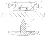
- FIG. 3 is a cross-sectional view of the snap attachment member, the flexible base material, and the snap member before insertion of the post portion according to the first embodiment.
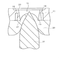
- FIG. 4 shows a snap attachment member, a flexible base material, and a snap member in the vicinity of the insertion port in a state where the post portion is further inserted into the insertion port and the flexible base material is lifted from the state of FIG. FIG. FIG.
- FIG. 5 shows a snap attachment member, a flexible base material in the vicinity of the insertion port in a state where the post portion has been inserted into the flexible base material by inserting the post part into the insertion port from the state of FIG. And it is an expanded sectional view of a snap member.
- FIG. 6 shows a snap attachment member, a flexible base material in the vicinity of the insertion port in a state where the post part penetrates the flexible base material by further inserting the post part into the insertion port from the state of FIG. And it is an expanded sectional view of a snap member.
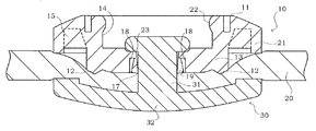
- FIG. 7 is a sectional view of the snap attachment member, the flexible base material, and the snap member in which the post portion is completely inserted from the state of FIG. 6 and the snap attachment member and the snap member are fixed.
- FIG. 8 is a perspective view of the rear surface side of the snap member according to the second embodiment.
- FIG. 9 is a cross-sectional view of the vicinity of the insertion port of the snap member according to the third embodiment.
- the configuration of the snap member according to the present invention will be described below in detail with reference to the drawings.
- the structure shown below is an illustration and the snap member which concerns on this invention is not limited to these.
- a female member is exemplified as the snap member, but the present invention is not limited to this, and a male snap member may be used.
- FIG. 1 is a perspective view of the rear surface side of the snap member 10 according to the first embodiment of the present invention
- FIG. 2 is a cross-sectional view of the snap member 10.
- FIG. 3 shows a cross-sectional view of the snap attachment member 30, the flexible base material 20, and the snap member 10 before the post portion 31 is inserted.
- the snap member 10 includes a member main body 11 and a protruding portion 12 formed on the back surface of the member main body 11.
- the member main body 11 includes a main body substrate 13 formed in a substantially disk shape, and a female fitting portion 14 protruding from the peripheral edge of the main body substrate 13 to the surface side.
- the fitting portion 14 is formed in a cylindrical shape, and includes an engaging portion 22 that protrudes radially inward at an upper end edge portion.
- the engaging portion 22 has a function of hooking and fixing the male snap member when the male snap member is fitted to the female snap member 10.
- the fitting portion 14 is provided with a ring-shaped protruding piece 21 that is folded outward from the upper end thereof and extends to the back surface side of the member main body 11.
- a plurality of projecting portions 12 are formed on the back surface of the member main body 11 so as to be sharpened downward.
- the projecting portion 12 is formed in a substantially tapered columnar shape in the present embodiment, but may be any shape as long as it has a shape that can be satisfactorily caught by the surface of the flexible substrate 20, for example, approximately It may be formed in a substantially pyramid shape such as a triangular pyramid shape or a substantially quadrangular pyramid shape, or may be formed in a substantially conical shape or the like.
- the plurality of protruding portions 12 are provided at substantially equal intervals in the circumferential direction of the member main body 11.
- the snap member 10 is made of an elastic material such as a resin material.
- the resin material for example, polyacetal resin, polyester resin, PBT resin (polybutylene terephthalate resin) or the like can be used.
- a plurality of reinforcing ribs 15 extending in the radial direction of the member main body 11 are formed from the outer surface of the main body substrate 13 to the inner surface of the protruding piece 21 of the fitting portion 14.
- the plurality of reinforcing ribs 15 are each formed in a rectangular parallelepiped shape or the like, and are provided at predetermined intervals in the circumferential direction of the member main body 11.
- An insertion portion 16 into which the post portion 31 of the snap attachment member 30 penetrating the flexible base material 20 is inserted is formed at a substantially central portion of the main body substrate 13 of the member main body 11.
- the insertion portion 16 includes a circular insertion port 17 provided on the back side of the member main body 11, that is, an inlet side of the post portion 31, and a circular opening 23 provided on the outlet side of the post portion 31. It has.
- the diameter of the insertion port 17 provided on the inlet side of the post part 31 is formed smaller than the diameter of the post part 31, and the diameter of the opening 23 provided on the outlet side of the post part 31 is formed larger than the diameter of the post part 31.
- the insertion portion 16 is formed in a tapered shape having a diameter that gradually increases from the insertion port 17 in the depth direction (the thickness direction of the main body substrate 13).
- the member main body 11 of the snap member 10 is provided with a groove portion 18 formed around the insertion port 17 of the insertion portion 16 via an annular wall portion 19.
- the groove portion 18 is preferably formed in an annular shape continuously around the insertion port 17 of the insertion portion 16.
- the groove portion 18 has a width that can accommodate the amount of displacement of the wall portion 19 that occurs when the post portion 31 is inserted into the insertion portion 16 and the wall portion 19 expands.
- the depth of the groove 18 is preferably not less than 1/4 and not more than 3/4 of the thickness of the main body substrate 13.
- the annular wall portion 19 is formed in a shape in which the radial thickness gradually decreases from the distal end to the proximal end.
- the snap attachment member 30 includes a base portion 32 and a post portion 31 that is formed so as to stand at a substantially central portion of the surface of the base portion 32 and penetrates the flexible base material 20 such as a cloth for clothes. ing.
- the base portion 32 is formed in a plate shape such as a substantially circular shape or a substantially rectangular shape, for example.
- the post part 31 is formed in a substantially cylindrical shape standing on the surface of the base part 32.
- the post portion 31 includes a columnar post body portion 33 extending from the surface of the base portion 32 and a triangular pyramid-shaped post top portion 34 extending from the post body portion 33.
- the base part 32 and the post part 31 can be formed of, for example, a resin material or a metal material. Among these, a resin material is particularly preferable from the viewpoints of cost, light weight, ease of molding, and the like.
- a resin material for example, polyacetal resin, polyester resin, PBT resin (polybutylene terephthalate resin) or the like can be used.
- the base portion 32 and the post portion 31 are integrally formed.
- a flexible base material 20 such as a cloth for clothing to which the snap member 10 and the snap attachment member 30 are attached is prepared.
- a snap member attaching device (not shown) is also prepared.
- the snap member attaching device includes a fixed base, a driving tool that moves up and down with respect to the fixed base, and a hammer (not shown) provided on the shaft core portion of the driving tool.
- the snap attachment member 30 is set on the fixing base of the snap member attachment device so that the post portion 31 side faces upward, and the snap member 10 is set on the driving tool so that the insertion port 17 faces downward.
- the driving tool of the snap member mounting device is lowered in a state where the flexible base material 20 is tensioned and interposed between the snap mounting member 30 and the snap member 10.
- the driving tool is lowered, as shown in FIG. 3, the post portion 31 of the snap attachment member 30 and the insertion portion 16 of the snap member 10 face each other on both sides of the tensioned flexible base material 20.
- the post portion 31 bites into the back surface side of the flexible base material 20 and lifts the flexible base material 20.
- the raised flexible base material 20 is inserted into the insertion portion 16 while the post portion 31 is inserted.
- the front end of the wall portion 19 bites into the surface side of the flexible base material 20 and tries to suppress the entanglement of the flexible base material 20 into the insertion portion 16.
- the plurality of protruding portions 12 of the snap member 10 bite into the flexible base material 20 to form a catch. Subsequently, when the driving tool is further lowered, as shown in FIG.
- the insertion port 17 of the insertion portion 16 is slightly opened by plastic deformation and the wall portion 19 is pushed.
- the wall portion 19 is formed in a shape in which the radial thickness gradually decreases from the distal end to the proximal end, the proximal end has a smaller thickness than the distal end and is easily deformed. Therefore, the pushed wall portion 19 is tilted about the base end and displaced so as to enter the groove portion 18 from the distal end.
- the groove portion 18 accommodates the amount of displacement of the wall portion 19 to absorb the pressing force from the post portion.
- the groove part 18 absorbs the displacement of the member main body 11 caused by the insertion of the post part 31, the movement of the member main body 11 with respect to the flexible base material 20 is suppressed, and the attachment position is stabilized.
- the post portion 31 penetrates the flexible base material 20 and protrudes from the opening 23 of the insertion portion 16 as shown in FIG. 6.
- the diameter of the insertion port 17 of the insertion part 16 is formed smaller than the diameter of the post part 31, and the insertion port 17 of the insertion part 16 is further opened by plastic deformation.
- the groove part 18 formed around the insertion port 17 of the insertion part 16 accommodates the displacement amount of the wall part 19 at this time as much as possible.
- the post portion 31 is formed in a tapered shape in which the insertion portion 16 gradually expands in the depth direction, a large force is applied after passing through the insertion port 17 having the smallest diameter in the insertion portion 16.
- the post portion 31 is not subjected to a large load while being inserted, the occurrence of buckling is also suppressed.
- the insertion port 17 of the insertion part 16 is opened by plastic deformation, it is not restricted to this, After deform
- the driving tool is further lowered and the post portion 31 is completely inserted into the insertion portion 16.
- the substrate surface of the snap attachment member 30 and the surface of the member main body 11 of the snap member 10 press and fix the flexible base material 20 respectively.
- the tip of the post portion 31 protrudes completely from the insertion portion 16.
- the hammer provided on the shaft core portion of the driving tool strikes the tip of the post portion 31 to expand and deform (flange attachment).
- the snap attachment member 30 and the snap member 10 are fixed to the flexible substrate 20 by caulking.
- FIG. 8 is a perspective view of the rear surface side of the snap member 40 according to the second embodiment of the present invention.
- the snap member 40 includes a member main body 41 and a protruding portion 42 formed on the back surface of the member main body 41.
- the member main body 41 includes a main body substrate 43 formed in a substantially disc shape, and a female fitting portion 44 protruding from the peripheral edge of the main body substrate 43 to the surface side.
- the fitting portion 44 is provided with a ring-shaped protruding piece 51 that is folded outward from the upper end thereof and extends to the back surface side of the member main body 41.
- a plurality of projecting portions 42 are formed on the back surface of the member main body 41 so as to be sharpened downward.
- the projecting portion 42 is formed in a substantially tapered columnar shape in the present embodiment, but may be any shape as long as it has a shape that bites into the surface of the flexible substrate 20 and is hooked well. It may be formed in a substantially pyramid shape such as a triangular pyramid shape or a substantially quadrangular pyramid shape, or may be formed in a substantially conical shape or the like.
- the plurality of protrusions 42 are provided at substantially equal intervals in the circumferential direction of the member main body 41.
- the member main body 41 and the protrusion 42 are made of an elastic material such as a resin material.
- the resin material for example, polyacetal resin, polyester resin, PBT resin (polybutylene terephthalate resin) or the like can be used.
- a plurality of reinforcing ribs 45 extending in the radial direction of the member main body 41 are formed from the outer surface of the main body substrate 43 to the inner surface of the protruding piece 51 of the fitting portion 44.
- the plurality of reinforcing ribs 45 are each formed in a rectangular parallelepiped shape or the like, and are provided at predetermined intervals in the circumferential direction of the member main body 41.
- An insertion portion 46 into which the post portion of the snap attachment member penetrating the flexible base material is inserted is formed at a substantially central portion of the main body substrate 43 of the member main body 41.
- the insertion portion 46 includes a circular insertion port 47 provided on the back surface side of the member main body 41, that is, an inlet side of the post portion 31, and a circular opening provided on the outlet side of the post portion 31 (not illustrated). As shown).
- the diameter of the insertion port 47 provided on the inlet side of the post part 31 is formed smaller than the diameter of the post part 31, and the diameter of the opening provided on the outlet side of the post part 41 is formed larger than the diameter of the post part 31.
- the insertion portion 46 is formed in a tapered shape having a diameter that gradually increases from the insertion port 47 in the depth direction (the thickness direction of the main body substrate 43).
- the member main body 41 of the snap member 40 is provided with a groove portion 48 formed through an annular wall portion 49 around the insertion port 47 of the insertion portion 46.
- the groove portion 48 is formed around the insertion port 47 of the insertion portion 46.
- the groove portion 48 has a width that can accommodate the amount of displacement of the wall portion 49 that occurs when the post portion 31 is inserted into the insertion portion 46 and the wall portion 49 expands.
- the depth of the groove portion 48 is preferably not less than 1/4 and not more than 3/4 of the thickness of the main body substrate 43.
- the annular wall portion 49 is formed in a shape in which the radial thickness gradually decreases from the distal end to the proximal end.
- a plurality of notches 50 extending in the depth direction of the insertion portion 46 are formed in the wall portion 49.
- the notches 50 are preferably formed at point-symmetric positions from the center of the insertion port 47 in order to expand the wall portion 49 in a balanced manner when the post portion of the snap attachment member is inserted.
- the number, width, and depth of the notches 50 are not particularly limited, but are appropriately determined to be optimal values in relation to the diameter of the post portion 31 and the elastic force of the material constituting the member main body 41, respectively.
- a plurality of notches 50 extending in the depth direction of the insertion portion 46 are formed in the wall portion 49 sandwiched between the insertion portion 46 and the groove portion 48. Therefore, when the post portion 31 of the snap attachment member 30 is inserted into the insertion portion 46 of the snap member 40, the wall portions 49 divided by the notches 50 are expanded outwardly by the pressing force from the post portion. Thereby, the insertion port 47 of the insertion part 46 is opened by elastic deformation, so that the pressing force from the post part 31 is absorbed. Therefore, the load on the post part 31 is suppressed well, and the occurrence of buckling can be prevented well.
- FIG. 9 is a cross-sectional view of the vicinity of the insertion port 67 of the snap member 60 according to the third embodiment.
- the snap member 60 includes a member main body 61.
- the member main body 61 includes a main body substrate (not shown) formed in a substantially disk shape, and a female fitting portion (not shown) protruding from the periphery of the main body substrate to the surface side.
- An insertion portion 66 into which the post portion 31 of the snap attachment member 30 penetrating the flexible base material 20 is inserted is formed at a substantially central portion of the main body substrate of the member main body 61.
- the insertion portion 66 includes a circular insertion port 67 provided on the back surface side of the member main body 61, that is, the inlet side of the post portion 31, and a circular opening 63 provided on the outlet side of the post portion 31. It has.
- the diameter of the insertion port 67 provided on the inlet side of the post part 31 is formed smaller than the diameter of the post part 31, and the diameter of the opening 63 provided on the outlet side of the post part 31 is formed larger than the diameter of the post part 31.
- the insertion portion 66 is formed in a tapered shape having a diameter that gradually increases from the insertion port 67 in the depth direction (the thickness direction of the main body substrate).
- the member main body 61 of the snap member 60 is provided with a groove portion 68 formed through an annular wall portion 69 around the insertion port 67 of the insertion portion 66.
- the groove portion 68 is formed around the insertion port 67 of the insertion portion 66.
- the groove portion 68 has a width that can accommodate the amount of displacement of the wall portion 69 that occurs when the post portion 31 is inserted into the insertion portion 66 and the wall portion 69 expands.
- the depth of the groove 68 is preferably not less than 1/4 and not more than 3/4 of the thickness of the main body substrate.
- the wall portion 69 is formed in a shape in which the thickness in the radial direction gradually decreases from the distal end to the proximal end.
- the wall 69 is formed so as to protrude from the surface of the member body on the side where the groove 68 is formed.
- the snap member 60 is formed so that the wall portion 69 protrudes from the surface of the member main body on which the groove portion 68 is formed.
- the post part 31 bites in from the back surface of the flexible base material 20 and lifts the flexible base material 20 when the part 31 is inserted into the insertion part 66, the protruding end of the wall part 69 is flexible. It is possible to prevent the flexible base material 20 from being caught in the insertion portion 66 by biting into the surface of the base material 20.
- Snap member 11 Member main body 16 Insertion part 17 Insertion port 18 Groove part 19 Wall part 20 Flexible base material 30 Snap attachment member 31 Post part 40 Snap member 41 Member main body 46 Insertion part 47 Insertion port 48 Groove part 49 Wall Part 50 Notch 60 Snap member 61 Member main body 66 Insertion part 67 Insertion port 68 Groove part 69 Wall part
Landscapes
- Slide Fasteners, Snap Fasteners, And Hook Fasteners (AREA)
Abstract
Description
そして、このような構成によれば、カシメ用突起が基布に打ち込まれたときに、貫通孔の周りに突設した環状壁が基布との摩擦力によって貫通孔の中心側へ変形し、カシメ用突起と貫通孔との間の隙間を小さくすることで、基布の一部がカシメ用突起によって貫通孔内に持ち込まれないようにすることができると記載されている。
そして、このような構成によれば、リベット部材の材料として硬い樹脂を使用した場合でも、突起の突出先端部の打撃による拡開変形を容易に行えて、突起の付け根や拡開変形部の付け根にクラックが発生することを防止でき、しかも突起による可撓性シートの貫通孔への引きずり込みを防止できると記載されている。
また、特許文献2に記載されたスナップ部材は、ポスト部(突起)を差し込む差込部(貫通孔)が、ポスト部の直径より小さな直径を有する小径孔部と大径孔部とを備えているが、このような2段構成に形成されていても、なおポスト部を差し込む際に大きな力を必要とし、さらに差し込む際のポスト部にかかる負荷が大きく、ポスト部が座屈してしまうという問題がある。
すなわち、本発明に係るスナップ部材は、円柱状のポスト部を備えたスナップ取付部材により可撓性基材に取り付けられるスナップ部材であって、前記スナップ部材は、前記可撓性基材を貫通したスナップ取付部材のポスト部が差し込まれる円形の差込口を有する差込部が形成された部材本体を備え、前記部材本体は、前記差込部の差込口の周囲に環状の壁部を介して形成された溝部を備え、前記差込部は、前記差込口の直径が前記スナップ取付部材のポスト部の直径より小さく、且つ、深さ方向に進むにつれて徐々に直径が大きくなるテーパ状に形成されている。
ここで、上述の「ポスト部の直径」とは、前記ポスト部における先端部位の直径であってもよく、側面の特定部位の直径であってもよい。
また、特に、本実施形態では、スナップ部材として雌型のものを例示するが、これに限られず、雄型スナップ部材を用いても良い。
(スナップ部材10の構成)
図1は本発明の実施形態1に係るスナップ部材10の裏面側の斜視図を、図2はスナップ部材10の断面図を示す。また、図3は、ポスト部31差し込み前の、スナップ取付部材30、可撓性基材20、及び、スナップ部材10の断面図を示す。
次に、本発明の実施形態1に係るスナップ部材10の、衣服の生地等の可撓性基材20への取り付け方法について図を用いて詳細に説明する。また、本実施形態では、スナップ取付部材30及びスナップ部材10を、スナップ部材取り付け装置(不図示)を用いて可撓性基材20に取り付ける方法について例示的に説明する。
続いて、可撓性基材20を緊張させてスナップ取付部材30とスナップ部材10との間に介在させた状態で、スナップ部材取り付け装置の打ち込み具を下降させる。打ち込み具が下降すると、図3に示すように、緊張した可撓性基材20を挟んだ両側において、スナップ取付部材30のポスト部31とスナップ部材10の差込部16とが対向する。
続いて、さらに打ち込み具を下降させると、図5に示すように、差込部16の差込口17が塑性変形により若干開くと共に、壁部19が押される。ここで、壁部19は、その先端から基端にかけて半径方向の肉厚がしだいに減少する形状に形成されているため、基端が先端に比べて肉厚が小さく、変形しやすい。従って、押された壁部19は、基端を中心にして傾き、先端から溝部18内へ入り込むようにして変位する。このとき、溝部18が、壁部19の変位量を収容することで、ポスト部からの押圧力を吸収する。このように、ポスト部31の差し込みに伴って生じる部材本体11の変位を溝部18が吸収するため、部材本体11の可撓性基材20に対する移動が抑制され、取り付け位置が安定する。
この状態でさらに打ち込み具が下降を続けることにより、打ち込み具の軸芯部に設けられたハンマーがポスト部31の先端部を打撃して拡開変形させる(フランジ付けする)ことによって、図7に示すように、スナップ取付部材30とスナップ部材10とが加締め止めにより可撓性基材20に固定される。
スナップ部材は、実施形態1に記載したものに限らず、例えば、以下に説明する実施形態2に係る構成であってもよい。
(スナップ部材40の構成)
図8は本発明の実施形態2に係るスナップ部材40の裏面側の斜視図を示す。
スナップ部材は、実施形態1及び2に記載したものに限らず、例えば、以下に説明する実施形態3に係る構成であってもよい。
(スナップ部材60の構成)
図9は、実施形態3に係るスナップ部材60の差込口67付近の断面図である。
11 部材本体
16 差込部
17 差込口
18 溝部
19 壁部
20 可撓性基材
30 スナップ取付部材
31 ポスト部
40 スナップ部材
41 部材本体
46 差込部
47 差込口
48 溝部
49 壁部
50 切り欠き
60 スナップ部材
61 部材本体
66 差込部
67 差込口
68 溝部
69 壁部
Claims (6)
- 円柱状のポスト部31を備えたスナップ取付部材30により可撓性基材20に取り付けられるスナップ部材10,40,60であって、
前記スナップ部材10,40,60は、前記可撓性基材20を貫通したスナップ取付部材30のポスト部31が差し込まれる円形の差込口17,47,67を有する差込部16,46,66が形成された部材本体11,41,61を備え、
前記部材本体11,41,61は、前記差込部16,46,66の差込口17,47,67の周囲に環状の壁部19,49,69を介して形成された溝部18,48,68を備え、
前記差込部16,46,66は、前記差込口17,47,67の直径が前記スナップ取付部材30のポスト部31の直径より小さく、且つ、深さ方向に進むにつれて徐々に直径が大きくなるテーパ状に形成されていることを特徴とするスナップ部材10,40,60。 - 前記溝部18,48,68が、前記差込部16,46,66の差込口17,47,67の周囲に連続して環状に形成されていることを特徴とする請求項1に記載のスナップ部材10,40,60。
- 前記溝部18,48,68は、前記差込部16,46,66に前記ポスト部31が差し込まれることで生じる前記壁部19,49,69の変位量を収容し得る幅を有することを特徴とする請求項1に記載のスナップ部材10,40,60。
- 前記壁部19,49,69は、先端から基端にかけて半径方向の肉厚がしだいに減少する形状に形成されていることを特徴とする請求項1に記載のスナップ部材10,40,60。
- 前記壁部49には、前記差込部46の深さ方向に延びる複数の切り欠き50が形成されていることを特徴とする請求項1に記載のスナップ部材40。
- 前記壁部69は、前記部材本体61における前記溝部68が形成されている側の表面から突出するように形成されている請求項1に記載のスナップ部材60。
Priority Applications (3)
| Application Number | Priority Date | Filing Date | Title |
|---|---|---|---|
| PCT/JP2009/060466 WO2010143255A1 (ja) | 2009-06-08 | 2009-06-08 | スナップ部材 |
| CN200980160401.0A CN102458174B (zh) | 2009-06-08 | 2009-06-08 | 按扣构件 |
| JP2011518155A JP5399487B2 (ja) | 2009-06-08 | 2009-06-08 | スナップ部材 |
Applications Claiming Priority (1)
| Application Number | Priority Date | Filing Date | Title |
|---|---|---|---|
| PCT/JP2009/060466 WO2010143255A1 (ja) | 2009-06-08 | 2009-06-08 | スナップ部材 |
Publications (1)
| Publication Number | Publication Date |
|---|---|
| WO2010143255A1 true WO2010143255A1 (ja) | 2010-12-16 |
Family
ID=43308526
Family Applications (1)
| Application Number | Title | Priority Date | Filing Date |
|---|---|---|---|
| PCT/JP2009/060466 Ceased WO2010143255A1 (ja) | 2009-06-08 | 2009-06-08 | スナップ部材 |
Country Status (3)
| Country | Link |
|---|---|
| JP (1) | JP5399487B2 (ja) |
| CN (1) | CN102458174B (ja) |
| WO (1) | WO2010143255A1 (ja) |
Citations (4)
| Publication number | Priority date | Publication date | Assignee | Title |
|---|---|---|---|---|
| JPS5026482Y1 (ja) * | 1970-02-25 | 1975-08-07 | ||
| JPS52132201U (ja) * | 1976-03-31 | 1977-10-07 | ||
| JP3019596U (ja) * | 1995-06-16 | 1995-12-19 | 木口 謙 | 糸を使わないでつけるスナップ |
| JPH08299028A (ja) * | 1995-05-12 | 1996-11-19 | Kiyoshi Takeda | スナップファスナー |
-
2009
- 2009-06-08 WO PCT/JP2009/060466 patent/WO2010143255A1/ja not_active Ceased
- 2009-06-08 JP JP2011518155A patent/JP5399487B2/ja active Active
- 2009-06-08 CN CN200980160401.0A patent/CN102458174B/zh active Active
Patent Citations (4)
| Publication number | Priority date | Publication date | Assignee | Title |
|---|---|---|---|---|
| JPS5026482Y1 (ja) * | 1970-02-25 | 1975-08-07 | ||
| JPS52132201U (ja) * | 1976-03-31 | 1977-10-07 | ||
| JPH08299028A (ja) * | 1995-05-12 | 1996-11-19 | Kiyoshi Takeda | スナップファスナー |
| JP3019596U (ja) * | 1995-06-16 | 1995-12-19 | 木口 謙 | 糸を使わないでつけるスナップ |
Also Published As
| Publication number | Publication date |
|---|---|
| JPWO2010143255A1 (ja) | 2012-11-22 |
| CN102458174B (zh) | 2014-09-03 |
| CN102458174A (zh) | 2012-05-16 |
| JP5399487B2 (ja) | 2014-01-29 |
Similar Documents
| Publication | Publication Date | Title |
|---|---|---|
| JP5540003B2 (ja) | ボタン取付用上金型 | |
| JP4790751B2 (ja) | クリップ | |
| JPWO2010007828A1 (ja) | 止め具 | |
| WO2011118645A1 (ja) | 部品の締結構造及びこれに用いるクリップ | |
| CN102413726B (zh) | 纽扣安装构件 | |
| JP2013053703A (ja) | ファスナー | |
| WO2015111231A1 (ja) | 留め具 | |
| JP5306462B2 (ja) | スナップ部材 | |
| JP5399487B2 (ja) | スナップ部材 | |
| JP5808346B2 (ja) | ハトメ取付方法 | |
| JP2009293661A (ja) | プラグ | |
| JP4121980B2 (ja) | スナップファスナー | |
| CN102458173B (zh) | 纽扣安装构件 | |
| JP2003310310A (ja) | スナップファスナー用の合成樹脂製雌型部材 | |
| JP5840484B2 (ja) | クリップ | |
| JP4725738B2 (ja) | 合成樹脂製スナップファスナー | |
| JP3239436U (ja) | 雄型係合部材及び雄型スナップボタン | |
| JP6826384B2 (ja) | 留め具 | |
| JP2005152059A (ja) | スナップファスナー | |
| JP2006055455A (ja) | スナップファスナー取付け用カシメパンチ | |
| JP7265424B2 (ja) | 留め具 | |
| JP2002070827A (ja) | プッシュナット | |
| JP2024013901A (ja) | 雄型係合部材及び雄型スナップボタン | |
| JP5368575B2 (ja) | ボタン及びボタン取付用上金型 | |
| JP2002168225A (ja) | プッシュナット |
Legal Events
| Date | Code | Title | Description |
|---|---|---|---|
| WWE | Wipo information: entry into national phase |
Ref document number: 200980160401.0 Country of ref document: CN |
|
| 121 | Ep: the epo has been informed by wipo that ep was designated in this application |
Ref document number: 09845780 Country of ref document: EP Kind code of ref document: A1 |
|
| WWE | Wipo information: entry into national phase |
Ref document number: 2011518155 Country of ref document: JP |
|
| NENP | Non-entry into the national phase |
Ref country code: DE |
|
| WWE | Wipo information: entry into national phase |
Ref document number: 73/CHENP/2012 Country of ref document: IN |
|
| 122 | Ep: pct application non-entry in european phase |
Ref document number: 09845780 Country of ref document: EP Kind code of ref document: A1 |